A Network Service Framework for Mobile Pervasive Computing
软件工程专业英语-Mobile Internet

• Stage Two began after 2006, along with the massive construction of 3G wireless broadband networks and rapid development of smartphones, and WAP being replaced by universal web protocols.(WAP).
2023/10/10
4
In this chapter, we present an overview of mobile Internet, standards of mobile Internet, business patterns and application prospect of mobile internet.
2023/10/10
7
7.1.1 Development
• The first access to the mobile Internet was commercially offered in Finland in 1996 on Nokia 9000 Communicator phone via the Sonera and Radiolinja networks.
2023/10/10
14
7.1.3 Characteristics——Benefits
•Convenience and portability: The basement of the Mobile Internet network is a three-dimensional network, GPRS, 3G, 4G, WLAN or seamless coverage composed by Wi-Fi, the mobile terminal devices have a characteristic which can connect network easily. •Timeliness and accuracy: People can make full use of the fragmented time in the life and work, accept and solve all kinds of information from the Internet. No matter which terminal devices you use, their personalized degree is quite high.
移动WiFi用户手册说明书
Thank you for purchasing the Mobile WiFi. This Mobile WiFi brings you a high speed wireless network connection. This document will help you understand your Mobile WiFi so you can start using it right away. Please read this document carefully before using your Mobile WiFi.For detailed information about the functions and configurations of the Mobile WiFi, refer to the online help on the web management page that comes with the Mobile WiFi.For detailed instructions for logging in to the web management page, refer to "Logging In to the Web Management Page" on page 16.Getting to Know Your Mobile WiFiNote:The Mobile WiFi function descriptions and illustrations in this document are for yourreference only. The product you have purchased may vary.Application ScenariosWi-Fi devices (such as smartphones, tablet computers, and game consoles) or computers can all access the Internet through Mobile WiFi. The specific connection procedure depends on the operating system of the Wi-Fi device or computer. Establish a connection according to your device's specific instructions.To access the Internet through a USB port connection, install the driver according to the instructions.Scenario 1: Connecting multiple devices through Wi-Fi Scenario 2: Connecting a single device through USBScenario 3: Connecting multiple devices through Wi-Fi and USB simultaneouslyAppearance❶SIM card slot ❺Screen❷Reset button ❻Power indicator ❸microSD card slot ❼Micro USB port ❹Power button ❽WPS buttonScreen❶Signal strength: Signal strength from weak to strong. ❷Network type●2G/3G/4G: Connected to a 2G/3G/LTE network.●R: Data roaming turned on.❸Wi-Fi●Wi-Fi turned on.●Number of connected Wi-Fi devices. ❹ Battery: Battery level from low to high.❺SMS● New messages.●Number of new messages. ❻ Network connection status Internet connection is set up. ❼Traffic statistics● Data traffic information. ●Connection time. Note:Data traffic information is for your reference only. For more accurate data traffic information, please consult your service provider.SSID and Wireless Network Encryption KeyWhen a Wi-Fi device establishes a connection to the Mobile WiFi for the first time, you may need to enter the default Service Set Identifier (SSID) and wireless network encryption key. These are printed on the Mobile WiFi. It is recommended that you can log in to the web management page and change your SSID and wireless network encryption key.In addition, press the WPS button twice to view the current SSID and wireless networkGetting StartedInstalling a SIM CardCaution:Use a standard SIM card compatible with the Mobile WiFi,otherwise you will damage your Mobile WiFi.Install the SIM card according to the illustration.Note:When removing the SIM card, open the tab and gently press the SIM card in, thenrelease. The card will automatically pop out.●Do not remove the SIM card when it is in use. Doing so will affect the performance ofyour Mobile WiFi and data stored on the SIM card may be lost.Installing the microSD CardInstall the microSD card according to the illustration.Note:●The microSD card is an optional accessory. If no microSD card is included in thepackage, please purchase one separately.●When removing the microSD card, open the tab and gently press the microSD card in,then release. The card will automatically pop out.●Do not remove the microSD card when it is in use. Doing so will affect theperformance of your Mobile WiFi and data stored on the microSD card may be lost. Charging the BatteryIf the battery has not been used for an extended period of time, recharge it before use. Method 1: Use the power adapter to charge the deviceNote:●Only use chargers compatible with theMobile WiFi and provided by adesignated manufacturer. Use of anincompatible charger or one from anunknown manufacturer may cause theMobile WiFi to malfunction, fail, or couldeven cause a fire. Such use voids allwarranties, whether expressed or implied,on the product.●The power adapter is an optional accessory. If it is not included in the package, youmay contact an authorized dealer to buy an adapter compatible with the Mobile WiFi.●The Mobile WiFi’s power adapter model is HW-050200X3W. X represents U, E, B, A, orJ, depending on your region. For details about the specific adapter model, contact anauthorized dealer.Method 2: Charge the device through a computer connectionUse the data cable provided with your device to connect the Mobile WiFi to the computer.Connecting to the Internet via Wi-FiThe Mobile WiFi's management parameters have been preset according to your operator's requirements. You can quickly connect to the Internetby following these steps:Step 1: Turn on the Mobile WiFiPress and hold the button until the screen lights up,indicating that the Mobile WiFi is turned on.Note:●Press and hold the button to turn off theMobile WiFi.●If your Mobile WiFi malfunctions or cannot be properly powered off, press and holdthe button for at least 10 seconds to forcibly power off your Mobile WiFi.Step 2: Establish a Wi-Fi connection (using a computer running the Windows XP operating system as an example)1. Ensure that the Mobile WiFi's Wi-Fi function is on.2. Select Start > Control Panel > Network Connections > Wireless Network Connection. Note:Before establishing a Wi-Fi connection, ensure that the computer is equipped with a wireless network adapter. If the computer indicates a wireless network connection, the wireless network adapter can be used. Otherwise, verify that your wireless networkadapter is working properly.3. Click View available wireless networks to view a list of available wireless networks.4. Select the wireless network connection with the Mobile WiFi's SSID and click Connect. Note:●If the wireless network connection is encrypted, enter the correct wireless networkencryption key.●Press the WPS button twice to view the current SSID and wireless network encryptionkey on the screen.5. Wait a moment for the wireless network connection icon to appear in the system tray inthe lower right corner of the computer screen. The wireless network connection is then established.Step 3: Connect to the InternetIf data is transmitted, the Mobile WiFi will automatically connect to the Internet. If data is not transmitted for a period of time, the Mobile WiFi will automatically disconnect from the network connection.Note:You can log in to the web management page and enable or disable the automatic dialing while roaming function. If this function is turned off, when the Mobile WiFi enters aroaming network, it will automatically disconnect from the Internet connection that has already been established. You will need to manually establish this network connection again.Logging In to the Web Management Page1. Make sure the connection between the Mobile WiFi and the Wi-Fi device or computer isworking normally.2. Open the browser, and enter http://192.168.1.1 in the address box.3. Enter the user name and password to log in to the web management page.Note:●The default user name is admin.●The default password is admin.Daily UseBattery Saving ModeIf the Mobile WiFi has been inactive for some time, the Mobile WiFi enters the standby mode, in which the power indicator blinks slowly and the display screen turns off. Pressing any button causes the display screen to light up.When the Mobile WiFi is being powered only by the battery, you can choose to enable or disable the automatic Wi-Fi turnoff function. If this function is enabled and if no Wi-Fi devices access the Mobile WiFi for a period of time, the Wi-Fi turns off automatically. You can press any button to turn the Wi-Fi on again.Verifying the PINIf the PIN verification function is enabled, log in to the web management page and enter the correct PIN according to the instructions. PIN/PUK codes are supplied by your operator along with the SIM card. For details, please consult your operator.Establishing a WPS Connectionsupports WPS, the wireless network encryption key isgenerated automatically and there is no need to enter itmanually. The steps for WPS connection are as follows:1. Turn on the Mobile WiFi.2. Turn on the Wi-Fi device to be connected to theMobile WiFi.3. Activate the Mobile WiFi's WPS.Note:4. Activate the Wi-Fi device's WPS.Note:For specific instructions for the Wi-Fi device, refer to the device's user manual.Restoring to Factory SettingsIf you forget some configuration parameters, you Array can restore the Mobile WiFi to its factory settingsand then configure the Mobile WiFi again.Press and hold the Reset button until the displayscreen turns off. The Mobile WiFi is then restored toits factory settings.Note:After you carry out this operation, the MobileWiFi's personal configuration parameters will all be deleted. All configurations on the webmanagement page will be restored to the factory settings.Example 1: Connecting to a Game Console (for example, PSP) through Wi-Fi1. On the PSP, turn on the WLAN.2. Choose Settings > Network Settings.3. Select Infrastructure Mode.4. Select New Connection, and enter theconnection name.5. Select Scan to search for wirelessnetworks. A list of access points will bedisplayed on the screen.6. Select the access point with the MobileWiFi's SSID, and press the ► button onthe PSP. Confirm the SSID, and enter thecorrect wireless network encryption key.7. Press the ► button to proceed to thenext step, and then press the X button tosave settings.8. Select Test Connection to test whetherthe network connection is successful.9. You can now open the browser andaccess the network.Example 2: Connecting to a Tablet Computer (for example, iPad) through Wi-Fi1. Touch Settings > WLAN to turn on WLAN.2. The tablet computer automaticallysearches for wireless connections anddisplays a list of access points.3. Select the access point with the MobileWiFi's SSID.4. If required, enter the correct wirelessnetwork encryption key, and tap Join.(The lock icon indicates that the encryptionkey is required to connect to this wirelessnetwork.)Note:Wi-Fi devices, such as an iPhone, iPod touch, PS3 and NDSi, can all access the Internet through the Mobile WiFi. For specific operations, refer to the Wi-Fi device's user manual.TipsWhen the Mobile WiFi is in use for an extended period of time, it will become warm and may overheat. Should this happen, the Mobile WiFi will automatically close the network connection and turn off to protect itself from damage. If this occurs, place the Mobile WiFi in a well ventilated space to allow the heat to dissipate, then turn it on and continue to use it as normal. If you are unable to use the Mobile WiFi as normal, try the following:●Consult the online help on the web management page.●Restart the Mobile WiFi.●Restore the Mobile WiFi to the factory settings.●Consult your operator.。
中移动家庭网关终端技术规范v3.0.0
中国移动通信企业标准QB-╳╳-╳╳╳-╳╳╳╳家庭网关终端技术规范T e c h n i c a l S p e c i f i c a t i o n f o r H o m e G a t e w a y版本号:3.0.0╳╳╳╳-╳╳-╳╳发布╳╳╳╳-╳╳-╳╳实施目录1. 范围 (1)2. 规范性引用文件 (1)3. 术语、定义和缩略语 (5)4. 设备总体定义 (9)4.1.设备在网络中的位置 (9)4.2.接口定义 (10)4.3.设备类型 (10)5. 接入型家庭网关 (11)5.1.接口要求 (11)5.1.1. 网络侧接口 (11)5.1.1.1. 网络侧接口描述 (11)5.1.1.2. 网络侧以太网接口要求 (12)5.1.1.3. PON接口要求 (12)5.1.1.4. TD-SCDMA接口要求 (12)5.1.1.5. TD-LTE接口要求 (12)5.1.2. 用户侧接口 (12)5.1.2.1. 用户侧以太网接口要求 (12)5.1.2.2. WLAN接口 (12)5.1.2.3. USB接口(可选) (12)5.2.功能要求 (13)5.2.1. 数据通信要求 (13)5.2.1.1. IP协议要求 (13)5.2.1.2. 数据转发功能要求 (13)5.2.1.3. DNS功能要求 (14)5.2.1.4. IPv4地址管理及拨号管理功能要求 (14)5.2.1.5. IPv6地址管理及拨号管理功能要求 (16)5.2.1.6. IPv4 NAT要求 (16)5.2.1.7. ALG要求 (17)5.2.1.8. 组播要求 (17)5.2.1.9. 其他功能要求 (17)5.2.2. 安全要求 (17)5.2.2.1. 防火墙 (17)5.2.2.2. 登陆WEB页面的安全要求 (17)5.2.2.3. 设备安全性 (18)5.2.3. QoS 要求 (18)5.2.4. VLAN功能要求 (19)5.2.5. USB扩展及管理(可选) (19)5.2.6. 设备发现要求 (19)5.2.6.1. UPnP (19)5.2.6.2. DLNA(可选) (19)5.2.7.1. 支持WLAN的开启和禁用 (20)5.2.7.2. 基本要求 (20)5.2.7.3. 多SSID要求 (20)5.2.7.4. WLAN安全要求 (20)5.2.7.5. WLAN QoS要求 (21)5.2.7.6. WPS要求 (21)5.2.8. 基本应用要求 (22)5.2.8.1. WLAN共享 (22)5.2.8.2. 家庭存储(可选) (23)5.3.性能要求 (23)5.3.1. 路由转发性能要求 (23)5.3.1.1. 吞吐量 (23)5.3.1.2. 地址学习 (23)5.3.1.3. 缓存大小 (23)5.3.1.4. 连接数量要求 (24)5.3.2. WLAN无线性能要求 (24)5.3.2.1. WLAN吞吐量性能要求 (24)5.3.2.2. WLAN覆盖性能要求 (24)5.3.2.3. WLAN接收灵敏度要求 (24)5.4.管理和维护要求 (24)5.4.1. 本地管理和配置要求 (24)5.4.1.1. 本地管理基本要求 (24)5.4.1.2. 用户分级管理 (25)5.4.1.3. 系统信息管理 (25)5.4.1.4. 基本配置 (25)5.4.1.5. 高级配置 (26)5.4.1.6. 设备管理 (27)5.4.1.7. 网络诊断 (27)5.4.1.8. 设备认证注册功能 (27)5.4.2. 远程管理要求 (29)5.4.2.1. 远程管理基本要求 (30)5.4.2.2. 远程参数配置和性能监测 (30)5.4.2.3. 远程故障诊断功能 (30)5.4.2.4. 设备告警功能 (30)5.4.2.5. 远程链路维持功能 (31)5.4.2.6. 软件远程管理 (31)5.4.2.7. 业务部署和控制 (31)5.4.2.8. PON上行家庭网关远程管理实现方式 (31)5.4.3. 日志功能要求 (32)5.5.预配置要求 (33)5.5.1. 预配置要求 (33)5.6.硬件要求 (34)5.6.1. 基本要求 (34)5.6.3. 硬件基本框图示例 (34)5.7.软件要求 (34)5.7.1. 基本要求 (34)5.7.2. 软件基本架构 (35)5.7.3. 软件接口要求 (35)5.7.4. 用户登录要求 (36)5.7.5. 系统升级要求 (36)5.8.配置界面要求 (36)5.8.1. 配置界面要求 (36)5.8.2. 配置界面用户权限要求 (36)5.9.设备标识要求 (38)5.10.外观及附件要求 (39)5.10.1. 运营商Logo要求 (39)5.10.2. 设备标签要求 (39)5.10.3. 网关指示灯要求 (40)5.10.4. 开关与按键要求 (41)5.10.5. 设备面板标识要求 (41)5.10.6. 设备接口要求 (41)5.10.7. 附件要求 (41)5.11.运行环境要求 (42)5.11.1. 供电要求 (42)5.11.2. 环境要求 (42)5.11.3. 抗电磁干扰能力 (42)5.11.4. 设备本身产生的电磁干扰要求 (42)5.11.5. 过压过流保护 (42)5.12.认证要求 (43)6. 接入型家庭网关支持物联网功能 (43)6.1.接入型家庭网关支持宜居通的功能要求(内置433M模块) (43)6.1.1. 433M模块要求 (43)6.1.2. 外围设备要求 (43)6.1.3. 业务功能描述 (43)6.1.3.1. 安防功能要求 (44)6.1.3.2. 家电控制功能 (44)6.1.4. 接入型家庭网关配置界面要求 (45)6.1.4.1.配置界面要求 (45)6.1.4.2. 配置界面用户权限要求 (46)6.2.接入型家庭网关支持基于低功耗W I F I的物联网功能要求 (48)6.2.1. 设备接入功能要求 (48)6.2.1.1. WiFi接入 (48)6.2.1.1.1. 接入型家庭网关要求 (48)6.2.1.1.2. 外设要求 (49)6.2.1.2. DHCP流程要求 (49)7. 宽带应用型家庭网关 (49)7.1.类型描述 (49)7.2.分体机接入设备要求 (49)7.3.分体机应用设备(机顶盒)要求 (50)7.3.1. 硬件要求 (50)7.3.1.1. 硬件、接口及按键要求 (50)7.3.1.2. 遥控器要求及参考设计 (53)7.3.1.3. 电源要求 (53)7.3.1.4. 配件要求 (53)7.3.1.5. 设备标识要求 (53)7.3.2. 网络侧接口要求 (54)7.3.3. 业务功能要求 (54)7.3.3.1. 互联网电视应用 (54)7.3.3.2. 多屏互动功能 (54)7.3.3.2.1. 概述 (54)7.3.3.2.2. 镜像功能 (54)7.3.3.2.3. 分享功能 (55)7.3.3.3. 家庭高清视频通话(可选) (55)7.3.3.4. 家庭卡拉OK功能(可选) (56)7.3.3.5. 语音交互功能 (56)7.3.4. 软件要求 (56)7.3.4.1. 操作系统要求 (56)7.3.4.2. 软件协议要求 (57)7.3.4.3. 编码及解码能力要求 (57)7.3.4.3.1. 编解码能力要求 (57)7.3.4.3.2. 音视频播放质量要求 (58)7.3.4.4. 屏幕管理要求 (58)7.3.4.5. 防刷机要求 (58)7.3.5. 管理要求 (59)7.3.5.1. 操作管理 (59)7.3.5.2. 软件管理 (60)7.3.5.3. 文件管理 (60)7.3.5.4. 配置管理 (60)7.3.6. 其他要求 (61)7.3.6.1. 供电要求 (61)7.3.6.2. 环境要求 (61)7.3.6.3. 噪声要求 (62)7.4.一体机设备要求 (62)7.4.1. 网络侧接口要求 (62)7.4.2. 网络接入功能要求 (62)7.4.3. 业务功能要求 (62)7.4.4. 软件要求 (62)7.4.5. 管理要求 (62)7.4.6. 硬件要求 (62)7.4.7. 其他要求 (62)7.4.7.1. 供电要求 (62)7.4.7.2. 环境要求 (63)7.4.7.3. 噪声要求 (63)8. 编制历史 (63)附录A省公司代码 (64)附录B设备故障消息(标准性附录) (65)B.1 告警编号规则 (65)B.2 设备告警信息列表 (66)附录C WIMO协议说明 (67)C.1设备类型和功能流程 (67)C.2网络连接 (68)C.3设备连接 (69)C.4媒体格式要求 (70)C.4.1视频编解码流程 (70)C.4.2 M-JPEG视频编解码方案 (70)C.4.3 H.264视频编解码方案 (70)C.4.4 音频编解码流程 (70)附录D手机遥控接口说明 .............................................................................. 错误!未定义书签。
移动通信网络规划部署与优化_南京邮电大学中国大学mooc课后章节答案期末考试题库2023年
移动通信网络规划部署与优化_南京邮电大学中国大学mooc课后章节答案期末考试题库2023年1.CBRA-MSG1类型中的MSG2消息中包含了参考答案:UL-GRANT_TC-RNTI_TA2.在5G的SBA架构中,AMF采用什么协议与其它NF通信?参考答案:HTTP3.MANO包括哪些功能?参考答案:VNFM_NFVO_VIM4.NFVI包含哪些层?参考答案:虚拟资源层_虚拟化层_硬件层5.典型的NFV参考架构框架是哪个组织提出的?参考答案:ETSI6.以太网交换机的转发表是如何生成的?参考答案:源地址学习形成7.AMF配置的到NRF的路由中,掩码是以下哪个?参考答案:255.255.255.2558.当以太网交换机收到目的地址为C的帧,但是其转发表中无对应表项,那么它如何操作?参考答案:向所有其他端口转发9.如何分割广播域?参考答案:使用VLAN技术10.交换机向Acess端口发帧时,将报文的VLAN信息剥离,直接发送出去。
参考答案:正确11.交换机从 trunk端口收到一个帧时,并发现该帧中包含VLAN信息,且本trunk端口不允许该 VLAN的数据进入。
则丢弃该帧。
参考答案:正确12.AMF和CUCP之间要配置以下哪个接口的对接数据?参考答案:N213.核心网:UDM需要规划Loopback地址。
参考答案:错误14.在5G核心网的设备配置中,交换机SW采用以下哪种线缆连接服务器?参考答案:成对LC-LC光纤15.5G承载网一般分为三个层次:()、()、()。
参考答案:核心层16.路由器根据什么地址来实现数据的转发?参考答案:IP地址17.全局同步栅格以ARFCN指定了所有频率的位置参考答案:正确18.路由器工作在OSI参考模型的第几层?参考答案:第三层19.核心网:光纤两端接口的速率应一致参考答案:正确20.每个运营波段有不同的GSCN取值范围和步长。
参考答案:正确21.以下哪个网元不属于5G的SBA架构?参考答案:MME22.在5G的SBA架构中,每个NF是通过哪个网元发现其它NF提供的服务的?参考答案:NRF23.在5G的SBA架构中,每个NF并不是点对点连接。
Araknis Networks Wi-Fi 安装指南说明书
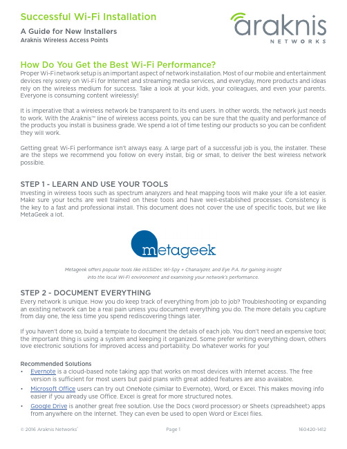
How Do You Get the Best Wi-Fi Performance?Proper Wi-Fi network setup is an important aspect of network installation. Most of our mobile and entertainment devices rely solely on Wi-Fi for Internet and streaming media services, and everyday, more products and ideas rely on the wireless medium for success. T ake a look at your kids, your colleagues, and even your parents. Everyone is consuming content wirelessly!It is imperative that a wireless network be transparent to its end users. In other words, the network just needs to work. With the Araknis™ line of wireless access points, you can be sure that the quality and performance of the products you install is business grade. We spend a lot of time testing our products so you can be confident they will work.Getting great Wi-Fi performance isn’t always easy. A large part of a successful job is you, the installer. These are the steps we recommend you follow on every install, big or small, to deliver the best wireless network possible.STEP 1 - LEARN AND USE YOUR TOOLSInvesting in wireless tools such as spectrum analyzers and heat mapping tools will make your life a lot easier. Make sure your techs are well trained on these tools and have well-established processes. Consistency is the key to a fast and professional install. This document does not cover the use of specific tools, but we like MetaGeek a lot.Metageek offers popular tools like inSSIDer, Wi-Spy + Chanalyzer, and Eye P.A. for gaining insightinto the local Wi-Fi environment and examining your network’s performance.STEP 2 - DOCUMENT EVERYTHINGEvery network is unique. How you do keep track of everything from job to job? Troubleshooting or expanding an existing network can be a real pain unless you document everything you do. The more details you capture from day one, the less time you spend rediscovering things later.If you haven’t done so, build a template to document the details of each job. You don’t need an expensive tool; the important thing is using a system and keeping it organized. Some prefer writing everything down, others love electronic solutions for improved access and portability. Do whatever works for you!Recommended Solutions• Evernote is a cloud-based note taking app that works on most devices with Internet access. The free version is sufficient for most users but paid plans with great added features are also available.• Microsoft Office users can try out OneNote (similar to Evernote), Word, or Excel. This makes moving info easier if you already use Office. Excel is great for more structured notes.• Google Drive is another great free solution. Use the Docs (word processor) or Sheets (spreadsheet) apps from anywhere on the Internet. They can even be used to open Word or Excel files.STEP 3 - CUSTOMER NEEDS AND SITE SURVEYKnow your CustomerSpend some time with your customer before the install to learn about their needs and set their expectations. Understanding expectations is essential to proper setup. Make sure to capture these pieces of information:• User types and their security needs• Coverage area and performance expectations• Types of wireless client devices in use, like computers, smart phones, media devices...• Applications that will be used on the network• Ask the customer to share floor plans if they’re available (preferably in a digital format)• Note what materials were used in constructionKnow the SiteT o provide great Wi-Fi, you need even coverage. T oo many or too few WAPs can cause equal amounts of problems, and due to interference, you can’t assume a single WAP will cover a given area. Walk around the site and look for these common trouble areas. Make notes of your findings and map them on the floor plan as you go:• Kitchen, utility rooms... any area with large electric appliances• Other wireless devices like cordless phones.• Obstacles that might block or deteriorate signal quality like metal studs, reflective glass, brick walls, etc. Next, scan the environment using your spectrum analyzer to see what channels or frequencies have interference. Scan from multiple locations, including possible trouble spots. You want a clear picture of the Wi-Fi environment around and throughout the job. Make note of existing Wi-Fi interference sources and other potential jamming signals on the floor map as you go.The image above shows MetaGeek Chanalyzer at work scanning a location for a new Wi-Fi install. The only interference we see is aboveis above the Wi-Fi spectrum.STEP 4 - PLAN ACCESS POINT LOCATIONSNow that you have a good idea of what you are getting into, go back to the floor map and decides where the access points should be installed. It’s recommended to:•Position the access points on the ceiling facing down toward clients in the most central part of the coverage area possible •Avoid natural sources of interference and signal disruption. Building materials like concrete, stucco, and metal studs can degrade signal strength.•Place access points with some overlap, but not a lot. -70dBm to -80dBm in overlap area is recommended.Cordless PhonesNanny CamsKitchen AreaMetal StudsConcrete/Brick WallsMicrowave Wireless Audio SystemCommon sources of Wi-Fi interferenceSTEP 5 - INSTALL THE ARAKNIS™ ACCESS POINTSWe designed our access points to be very installer friendly. The included mounting plate attaches to all standard junction box types and the access point snaps on without tools. Plus, standard PoE (Power over Ethernet) means one cable can be run for both network and power (PoE injector or PoE switch required). Follow the quick start guide in the box for specific installation steps.Once you have the cables for the access points installed, we highly recommend using a network analyzer to validate each run. This tool not only tells you if each connector is terminated correctly, it also tests the entire cable to be sure it’s in spec and transmitting data correctly. No more time lost searching for cable issues when something doesn’t work!STEP 6 - CLAIM IN OVRC AND CONFIGURE ACCESS POINTSWhat is OvrC?OvrC is a cloud management server that allows you to monitor, troubleshoot, and configure your Araknis devices from anywhere on the Internet through your OvrC browser or mobile app. Equipment is organized by location and you get instant notifications when network issues arise. You can change basic device settings right in the app, or use Web Connect to log into the local interface with no port forwarding required.Learn more at .Claiming Your Device in OvrCThe access point requests a DHCP IP address when it powers on, then connects to the OvrC server once an Internet connection is found. T o claim the device:1. Create or select a customer location and click + DEVICE.2. Enter the MAC address and Service T ag (ST) number (found on the bottom of the WAP and also on thebox). OvrC also scans the network for other enabled devices as you claim the first one, so you can set up an entire job in a few seconds.3. Name the device. Use a name that will help remember the device location and purpose.4. Click Save to complete the process. At this point, your device will appear in the job’s device list. Updating FirmwareAlways update the firmware (if available) before configuring your device. You will be notified in the app any time a device has new firmware available.Configuring Basic Wireless Settings in OvrCAt a minimum, you should configure the following settings before initial testing of the network. All of these settings are found on the Configure tab of the device page.1. Configure SSIDs per customer and job requirements. Use WPA2-PSK unless the requirements make youchoose another security standard.2. Configure the same SSIDs on both 2.4GHz and 5GHz radios and enable Band Steering.3. Configure the Guest Network feature (if required). Keep in mind:• The Guest Network feature is meant to be used in networks with a single access point hosting that SSID because the feature uses a separate DHCP server.• If a Guest Network is required to span across multiple access points using Fast Roaming, see the full product manual for setup instructions.Configuring Other Settings Using OvrC Web ConnectWe designed the Web Connect feature to access the full user interface from OvrC in just a few clicks. Use this feature to change settings that aren’t found on the Configure tab in OvrC. See the full product manual for detailed instructions.Default LoginUsername araknisPassword araknisSTEP 8 - TEST AND VALIDATENow that you feel comfortable about your wireless setup, start testing the performance of the network to make sure everything is working as advertised. Start by running continuous ping tests to the router while roaming around the location. Then test a couple of the applications the customer told you about so the customer is happy when they get your product. Make sure to push the limits when testing to expose any possible issues. STEP 9 - BACKUP YOUR FILESYou have done all the hard work, now make sure you document everything for future reference. Back up the configuration and log files from all of your access points. Make notes about special cases in that particular job site (each job site has one of those!). This will make your life a lot easier in the future in case the customer calls for help. And they always do.STEP 10 - SHARE WITH CUSTOMER AND CLOSEThis is an optional step, but if you want to set yourself apart, share a standard report document with your customer. Show them all the hard work and science that went into your product. Give them confidence in their choice and your abilities to deliver a phenomenal wireless network.These are the steps we recommend you get into the habit of performing on each job. No matter the size. Yes, it’s a time investment but this investment will pay off when you have fewer customer calls and a product you can stand behind.Happy Installing!。
A Design of Framework for Smart Services of Robots in Intelligent Environment

A Design of Framework for Smart Services of Robots inIntelligent EnvironmentJoo-Hyung Kim1, Dong Won Kim2,*, Bum-Jae You3, and Gwi-Tae Park1,*1 Department of Electrical Engineering, Korea University, Seoul, Korea{proteus99,gtpark}@korea.ac.kr2 Department of Digital Electronics, Inha Technical College, Incheon, Rep. of Koreadwnkim@inhatc.ac.kr3 Center for Cognitive Robotics Research, Korea Institute of Science and Technology,Seoul, Koreaybj@kist.re.krAbstract. This paper presents a framework for smart services of robots in anintelligent environment. Within such intelligent environment, the target platformconsists of service robots and a framework for smart services including taskallocation and task scheduling. For task allocation, we use an auction-basedmethod and a knapsack problem algorithm. In this paper, the characteristics ofthe algorithm for allocation balancing are to delegate executing task to anotherrobot, to reallocate the delayed task to more than one robot, and to withdrawover-allocated robots from the current task.Keywords: intelligent environment, smart services, task management.1 IntroductionRecently, computer networks have developed by many researchers and have become an important part of our daily lives. Intelligent environment is one of such computer networks, and it enables to accomplish diverse services, such as visitor guidance and indoor surveillance [1]. The environment is able to monitor what is happening in it, to communicate with their inhabitants, and to make a decision something important. In [2], sensing and reacting context, information sensed to characterize the situation of the people, activities, interaction between user and application are prominent characteristic of the intelligent environment. In [3], "Intelligent Space" was proposed by Lee et al for interaction between human and space based on intelligent environment. In the space, a robot is used as a physical agent for offering human-centered services [4], [5].In such an intelligent environment, the more people require diverse services, the more complex and huge the system becomes, and the role of robots as physical agent for offering smart services becomes more and more various and important. Thus, we need network based service framework to manage service tasks of robots.D. Ślęzak et al. (Eds.): CA 2009, CCIS 65, pp. 55–61, 2009.© Springer-Verlag Berlin Heidelberg 200956 J.-H. Kim et al.2 Architecture for Intelligent EnvironmentsIn this paper, we use a Resource Sharing Architecture (RSA) [6] as an architecture for an intelligent environment. The main focus of RSA is to share physical resources, and to organize them effectively for supporting high quality services. And, the most important characteristic of RSA is that it makes a robot overcome something physical. The structure of RSA consists of physical resources and service objects. Physical resources are devices such as mobile robots, cameras and so on. Some of them obtain data from the environment, and transmit the data to service objects via local area network. The others provide information to human who wants to know. Whereas service objects, such as robot navigation and room cleaning service, create significant information using data transmitted from physical resources and inform the information to other services, so that an intelligent space can obtain states and abilities of physical devices connected with network. According to the relation of each service object, they are classified into three categories as follows:1.Fundamental service: It’s a service object directly connected with physical devices.Such objects obtain data from sensors, or transmit useful information to human using devices. And the services inform data to inherited service objects.2.Inherited service: It’s organized by more than one fundamental service object andother inherited service objects. It uses the results of fundamental services, and creates visual or acoustic information for transmitting to iSpace service.3.iSpace service: It’s an intelligent service object by combined diverse serviceobjects as mentioned above (i.e. fundamental service and inherited service), which is able to carry out an intelligent task such as room cleaning or visitor guidance.3 Framework for Smart Services Based on RSAIn this paper, we design a multi agents based framework using a RSA. The framework consists of some robot groups and a task management group as shown in Fig. 1. In a robot group, each robot agent uses some services to control each robot. In a task management group, each task management agent can know what the space should do using information obtained from the diverse services.3.1 Robot AgentA robot agent monitors the state of a robot, and creates services to execute the assigned tasks. When a task is assigned to a robot agent, a robot starts carrying out the task using created services. If the executing task is stopped by some event, the agent informs the state of the interrupted task to a task management agent so as to be continued the task by other robot agents.3.2 Robot GroupAccording to the ability of each robot, they can be divided into more than one group. In case of a cooperative work, a task management agent makes a robot group, and add robots for carrying out the assigned task to the group.A Design of Framework for Smart Services of Robots in Intelligent Environment 573.3 Task Management AgentA task management agent plans the schedule of the robot's task. To manage the tasks, the agent acquires information from some services and robot agents, and creates the task list of robots to manage assigned tasks, and allocates the tasks to best candidates. If interrupted tasks remain in the task list, the agent can reallocate the tasks to other robots. All processes related to task scheduling and task allocation are decided by the task management algorithm which is included in the agent. We will deal with the algorithm for task management in the following section.3.4 Task management groupA task management group is a set of task management agents. If the group coordinates the needed service to an appropriate task management agent, then each task management agent executes smart services.Fig. 1. Overview of framework for smart services4 Smart Service Management Algorithm for Multi-robotIn Intelligent environment, people can be provided physical service by robots and other devices. Thus, a task management agent should manage the tasks of both robots and devices. In this paper, we only focus on the task of robots, and the assumptions of tasks that we consider are described as follows:1.A task can be decomposed into more than one independent sub-task.2.A task can be interrupted by an event, and the task can be continued by otherrobots.Fig. 2 depicts a flow of an algorithm for task management. A task management agent selects robots to carry out the assigned tasks, and informs to a robot agent. The characteristics of the proposed task management algorithm are to delegate executing task to another robot, to reallocate a delayed task to more than one robot and to58 J.-H. Kim et al.Fig. 2. Flow of task managementwithdraw over-allocated robots from the current task. In this paper, we implement two algorithms for task management of service robot as followed subsections.4.1 How to Select the Best RobotTo solve the problem for selecting the best robot, we consider single-robot of tasks and single-task of robots . In case of single-robot of tasks , the tasks are just inserted into the task list using an auction-based method [7]. However, in case of single-task of robots , when the decomposed tasks are inserted into the task list, we should consider effective decomposition of the task so as to distribute equally the workload of robots. In the case of a cooperation work, this approach can reduce the waiting time to start the assigned tasks with other robots. In order to solve the problem, we apply a knapsack problem. Specially, we wish to calculate the workload [,]W n w using equation (1), so as to distribute equally the task time of all robots.max([1,],[1,])([,][1,](n n n n W n w w W n w w w w W n w W n w −+−−≤⎧=⎨−>⎩ (1) where w is the average time of tasks, i w is the expected time of i th task, and n is the number of robots. Here, we calculate all the values of the array [,W n w using the recursive expressions above to calculate subsequent values.4.2 Allocation BalancingIn general, insufficient allocation of physical resources may bring about the task delay. On the other side, over-allocation for completing an assigned task quickly is not good. A good allocation is to complete an assigned task almost at a prearranged time and to carry out tasks as many as possible using given robots. In this paper, we consider the deadline of assigned task for dynamic task reallocation. The objective of allocation balancing is to reallocate a delayed task to other robots and to withdraw over-allocated robot from the current task. The algorithm predicts the reallocation point x according to the progress of the assigned task. The equation for predicting is expressed as follows:A Design of Framework for Smart Services of Robots in Intelligent Environment 59 ()''11x l ii i i i i x T n t c n t c p ==+⎡⎤⎡⎤=++⎣⎦⎣⎦∑∑ (2)where l is the number of total task, n i is i th task, 'i t is the measured time of i th task, c isthe number of allocated robots, p is the number of predicted robot for additional allocation, and x is prediction step. T includes the number of total task and the time of total task.5 Case Study: Simulation of Smart Services of Multi-robotIn this paper, we evaluate the proposed algorithm through two simulation scenarios. In the simulations, there are three mobile robots. And, we set up cleaning scenario to evaluate the algorithm, and assume that the robots have same ability. In the first scenario, we compare an auction-based method with a knapsack problem to evaluate task allocation algorithm. In second scenario, we evaluate the proposed algorithm for allocation balancing according to a change of the task time.5.1 Evaluation for Selecting the Most Appropriate RobotsThe objective of this simulation is to evaluate the proposed task management algorithm using a knapsack problem whether the algorithm distributes equally the workload of robots. The scenario for evaluating is as follows: Scenario 1Step 1: There are three robots. And 30 tasks will be allocated to robots. The task time is 10 or 50. Task time is generated randomly every step.Step 2: By an auction-based method, a task management agent allocates 30 tasks to robots.Step 3: By a knapsack problem, a task management agent allocates the same tasks to robots.Fig. 3 represents the results of task allocation using an auction-based method and using a knapsack problem. The lines in the figure show the cumulative time of tasks assigned to robots every step. In the experimental result, our method for the balance of robot's workload shows more effective than an auction-based method.Fig. 3. Comparing auction-based method with knapsack problem60 J.-H. Kim et al.5.2 Evaluation for Allocation BalancingIn this scenario, we evaluate the proposed algorithm which allocates robots dynamically to complete the assigned task by deadline. The scenario is as follows: Scenario 2Step 1: Robot 1 and Robot 2 have to carry out Task B. However, the executing time of Task B is reduced because of the delay of Task A.Step 2: According to the task schedule, a task management agent allocates Task B to Robot 1 and Robot 2.Step 3: A task management agent monitors the state of Task B, and allocates the task to Robot 3 so as to complete the task within deadline.Step 4: In opposition, when Task A is completed earlier than the schedule, a task management agent withdraws over-allocated robots from task B.At first, we measured the average time (i.e., about 43,000 seconds) of Task B, and considered two cases which are the increase of the task executing time and the decrease of the time. Table 2 and Table 3 depict the result of the measured task time and the predicted point for additional allocation according to the change of the task time. In the tables, the value of 49th / 50th means that the 49th task is allocated to Robot 3 in 50 independent tasks. And, we calculated the ratio of task delay from the result of the tables using equation (3).Table 1. Case 1: Decrease of the executing time of the taskTask time 42,000 41,000 40,000 39,000 38,000 Measured time 42,182 41,588 40,994 39,504 37,857 Predicted point 49th / 50th 46th / 50th 43th / 50th 37th / 50th 36th / 50th Table 2. Case 2: Increase of the executing time of the taskTask time 44,000 45,000 46,000 47,000 48,000 Measured time 43,897 44,038 45,859 47,143 48,229 Predicted point 47th / 50th 46th / 50th 44th / 50th 42th / 50th 41th / 50th() Ratio of delay%task time measured timetask time−=(3)In the experiment result, the ratio of task delay is about 1.054% in the case 1 and about -0.379% in the case 2. Fig. 4 shows the reliability of the proposed algorithm for allocation balancing. In case 1, Task B is delayed in an average of 425 seconds with a standard deviation of 487 seconds, and the reliability is about 82%. In case 2, Task B is completed early in an average of 167 seconds with a standard deviation of 458 seconds, and the reliability is about 87%.A Design of Framework for Smart Services of Robots in Intelligent Environment 61Fig. 4. Reliability of task deadline6 Conclusions and Future WorksIn this paper, we proposed a framework for smart services of robots in an intelligent environment. The important characteristics of the proposed framework are to delegate executing task to a robot, to reallocate the delayed task to more than one robot and to withdraw over-allocated robots from the current task. In near future, we improve the proposed framework for carrying out complex services using both robots and physical devices.Acknowledgments. This work was supported by the Korea Institute of Science and Technology(KIST).References1.Weiser, M.: The computer for the twenty-first century. Sci. Amer. 265, 94–100 (1991)2.Qin, W., Suo, Y., Shi, Y.: CAMPS: A Middleware for Providing Context-Aware Servicesfor Smart Space. In: Chung, Y.-C., Moreira, J.E. (eds.) GPC 2006. LNCS, vol. 3947, pp.644–653. Springer, Heidelberg (2006)3.Lee, J.H., Hashimoto, H.: Intelligent Space: its concept and contents. Adv. RoboticsJournal 16(4), 265–280 (2002)4.Yamaguchi, T., Sato, E., Takama, Y.: Intelligent Space and Human Centered Robotics.IEEE Trans. on Industrial Electronics 50(5) (October 2003)5.Lee, J.H., Morioka, K., Ando, N., Hashimoto, H.: Human Centered Ubiquitous Display inIntelligent Space. In: 33rd Annual Conference of Industrial Electronics Society 2007, Taipei, Taiwan, November 2007, pp. 22–27 (2007)6.Lee, B.J., Lee, H.G., Lee, J.H., Park, G.T.: A design of a data accessing service for a real-time vision service in the resource sharing architecture. In: Proc. IEEE Intl. Conf. Robotics Autom., pp. 1235–1240 (2002)7.Shah, K., Meng, Y.: Communication-Efficient Dynamic Task Scheduling for HeterogeneousMulti-Robot Systems. In: Proc. IEEE Int. symposium Comp. Intelli. Robotics & Autom., pp. 230–235 (2007)。
A.N.T

2 Previous work
The concept of software agent was proposed by Kahn and Cerf, 1988] in the context of information processing. In 1994, White, 1994] proposed Telescript, a product that greatly opened the eld of mobile agents. A few years later, Gray, 1996] presented Agent Tcl (later known as D'Agents ). In the same time, distributed natural systems were studied and a nature inspired paradigm began to rise from the work done in ethology by Bonabeau and Theraulaz, 1994]. Colorni et al, 1991] have been the rst to propose an antbased algorithm for classic constraints satisfaction problems. In the domain of telecommunications, Appleby and Steward, 1994] were the rst to propose an agent based simulation for control, followed by Schoonderwoerd et al, 1997]. Our own work mixes ideas inspired by ethology with the principle of mobile agents evolving on a computer networks.
Android 网络管理

Android 网络管理系统中对网络的判断和选在是在Connectivityervice这个服务中来处理的,在系统启动的时候会启动这个系统服务:系统启动完毕后,ConnectivityService在系统启动的时候就启动了。
在android内部,用framework/base/core/res/res/values/config.xml中定义了网络的类型:<string-array translatable="false" name="networkAttributes"><item>"default,wifi,0"</item><item>"default,mobile,0"</item><item>"mms,mobile,1"</item><item>"supl,mobile,1"</item><item>"dun,mobile,1"</item><item>"hipri,mobile,2"</item></string-array><string-array translatable="false" name="radioAttributes"><item>"wifi,1,1"</item><item>"mobile,0,1"</item></string-array>ConnectivityManager定义了向对应的字符串常量:public static final int TYPE_MOBILE = 0;/*** The Default WIFI data connection. When active, all data traffic* will use this connection by default. Should not coexist with other* default connections.*/public static final int TYPE_WIFI = 1;/*** An MMS-specific Mobile data connection. This connection may be the* same as {@link #TYPEMOBILE} but it may be different. This is used* by applications needing to talk to the carrier's Multimedia Messaging* Service servers. It may coexist with default data connections.* {@hide}*/public static final int TYPE_MOBILE_MMS = 2;/*** A SUPL-specific Mobile data connection. This connection may be the* same as {@link #TYPEMOBILE} but it may be different. This is used* by applications needing to talk to the carrier's Secure User Plane* Location servers for help locating the device. It may coexist with* default data connections.* {@hide}*/public static final int TYPE_MOBILE_SUPL = 3;/*** A DUN-specific Mobile data connection. This connection may be the* same as {@link #TYPEMOBILE} but it may be different. This is used* by applicaitons performing a Dial Up Networking bridge so that* the carrier is aware of DUN traffic. It may coexist with default data* connections.* {@hide}*/public static final int TYPE_MOBILE_DUN = 4;/*** A High Priority Mobile data connection. This connection is typically* the same as {@link #TYPEMOBILE} but the routing setup is different.* Only requesting processes will have access to the Mobile DNS servers* and only IP's explicitly requested via {@link #requestRouteToHost}* will route over this interface.*{@hide}*/public static final int TYPE_MOBILE_HIPRI = 5;/** {@hide} */public static final int MAX_RADIO_TYPE = TYPE_WIFI;/** {@hide} */public static final int MAX_NETWORK_TYPE = TYPE_MOBILE_HIPRI;public static final int DEFAULT_NETWORK_PREFERENCE = TYPE_WIFI;并设置了默认的网络连接是TYPE_WIFI.ConnectivityManager的方法是通过AIDL的使用,调用ConnectivityService中的方法来实现的。
- 1、下载文档前请自行甄别文档内容的完整性,平台不提供额外的编辑、内容补充、找答案等附加服务。
- 2、"仅部分预览"的文档,不可在线预览部分如存在完整性等问题,可反馈申请退款(可完整预览的文档不适用该条件!)。
- 3、如文档侵犯您的权益,请联系客服反馈,我们会尽快为您处理(人工客服工作时间:9:00-18:30)。
Using augmented service by seamless migration: When you work in front of your computer, your mobile phone rings. After you pick it up, what make you surprised is that the caller’s live video is displayed on your computer screen though the user’s mobile phone can display and capture the live video. Vice versa, your live video is also displayed on the caller’s computer screen. III. CHALLENGES Practical realization of the above application scenarios will require us to solve many difficult design and implementation problems. The following is our consideration when the framework is designed: Zero-configuration: Manual configuration is timeconsuming and difficult. If a user remains in a new computing environment for only 15 minutes, he does not want to spend the first 10 minutes configuring his mobile device manually. For example, a user want print a document in a new environment. Firstly he must configure his network connection, find a printer in the environment, install the driver of the printer and print the document. The process is boring and unacceptable. The most convenient method for user is that an interface is returned after he send “print” request. Next, what done by the user is only find the printed file in his mobile device and click “Print” button. Auto-configuration is important [6]. Service Discovery: The second challenge is how to cope with a large variety of services in the environment. Services are the applications with well-known interfaces to perform computation or actions on behalf of users, such as projector, printer, music server, web service and etc. You can get details information in [7]. Context Awareness: The third challenge is to obtain the information needed to function in a context-aware manner and to implement a context-aware system. A pervasive computing system must be cognizant of its user’s state and surrounding, and must modify its behavior based on this information. Dey defined context as “any information that can be used to characterize the situation of an entity. An entity is a person, place, or object that is considered relevant to the interaction between a user and an application [8]’’. Context-awareness enables mobile user to use the nearest and idle projector in the first scenario. Adaptive Service Synthesis: Service Synthesis is the post-processing and filtering operation. For example, in the second scenario, the PDA taken by user has only a small and gray display screen. So the system must rescale and gray the picture of “Chinese Chess” to him. Another example is that TTS technology should be adopted if a mobile user “browses” notice in a new environment by mobile phone (Mobile phone’s screen is small so that it is hard to read a long notice on it. On contrary, its “speaker” function easily enables the user listen to the notice). Seamless Service Mobility: Service Mobility is the capability of service being transported from one device to another by finding equivalent functions. For example, in the third scenario, though the user’s mobile phone can display and capture the live video, the quality is very low due to limited bandwidth of cellular communication technology. The environment has equivalent function and
Fig.1. Mobile Devices in the Mobile/Pervasive Computing Paradigm
II. APPLICATION SCENARIOS Here are three possible scenarios, which are just for purposes of illustration and not limitation. We have implemented the first one as a test-bed for our platform. Using service in the environment: When you go to ICCT2003 conference with your laptop, you meet with some friends in the same research field. You decide to make a presentation to them about your current research achievement. So you open your laptop, and search for a nearby projector. You get a response from a projector in the next door. After you go to the room with your friends, you launch the service and press “start” button. Consequently, your laptop’s screen is displayed on the wall by the projector so that you can give your presentation. Using service provided by peers: When you fly to Beijing Capital International Airport from Toulouse Blagnac Airport, you may transfer in Paris Charles de Gaulle International Airport. It is very boring since you have to wait for another two hours before your next flight in the CDG lounge. So you use search for “games”. You find another traveler who launches a “Chinese Chess” game, which is just your favorite. So you connect to his device and play with him.