arcgis生成界址点成果表代码
arcgis代码块

arcgis代码块ArcGIS是由美国ESRI公司开发的一款地理信息系统软件,被广泛应用于地理信息处理、分析、可视化等领域。
作为一名内容创作者,我们需要了解并掌握一些ArcGIS的代码块,以便更好地开展相关的工作。
下面,我们来介绍一些常用的ArcGIS的代码块及其作用。
1.绘制点可以通过以下代码在地图上绘制一个点:```pythonimport arcpyarcpy.env.workspace="C:/data"arcpy.CreateFeatureclass_management("C:/data","points.shp","P OINT")cur=arcpy.InsertCursor("c:/data/points.shp")# 创建一个新的点pt=arcpy.Point(100,100)row=cur.newRow()row.shape=ptcur.insertRow(row)del cur```其中,“c:/data/points.shp”为点的存储路径,“pt=arcpy.Point(100,100)”为点的坐标。
2.绘制线可以通过以下代码在地图上绘制一条线:```pythonimport arcpyarcpy.env.workspace="C:/data"arcpy.CreateFeatureclass_management("C:/data","lines.shp","POLYLINE")cur=arcpy.InsertCursor("c:/data/lines.shp")# 创建一条新线lineArray=arcpy.Array()lineArray.add(arcpy.Point(0,0))lineArray.add(arcpy.Point(100,100))feat = cur.newRow()feat.shape = lineArraycur.insertRow(feat)del cur```其中,“c:/data/lines.shp”为线的存储路径,“lineArray.add(arcpy.Point(0,0))”和“lineArray.add(arcpy.Point(100,100))”为线的两个端点坐标。
pythnon语句arcgis生成点

pythnon语句arcgis生成点要在ArcGIS中使用Python生成点,您需要使用ArcPy模块。
以下是一个简单的示例代码,演示如何使用Python在ArcGIS中生成点:pythonimport arcpy# 设置工作空间和输出点要素类arcpy.env.workspace = r"C:\data"output_points = "output_points.shp"# 定义点的坐标x = 100y = 200# 使用点工具创建点要素arcpy.CreateFeatureclass_management(arcpy.env.workspace, output_points, "POINT") fc = arcpy.Describe(output_points)fields = arcpy.ListFields(fc)with arcpy.da.InsertCursor(output_points, s) as cursor:cursor.next()# 在点要素类中插入新记录cursor.insertRow([x, y])print("Point created successfully.")在这个例子中,我们首先导入ArcPy模块,并设置工作空间和输出点要素类的名称。
然后,我们定义要生成的点的坐标,并使用CreateFeatureclass_management函数创建一个空的点要素类。
接下来,我们使用Describe函数获取新创建的要素类的属性,并使用ListFields函数获取所有字段的名称。
然后,我们使用InsertCursor对象插入新记录,该记录包含点的坐标。
最后,我们打印一条成功消息。
GIS应用 地理信息系统 地形点编码及展点说明

地形点编码及展点程序使用说明(按全站仪坐标数据文件自动分层画点及初步连线)(一)全站仪数据文件SET22D及SET230R全站仪输出的坐标数据文件为每个细部点一行字符串,其结构形式为:点的采集方式(1~4位),点号(17~20位),X坐标(21~36位),Y坐标(37~52位),高程H(53~68位),代码CD(69~84位)。
本程序采用“六位地形编码法”,故仅用其前6位。
(二)“六位地形编码法”的代码规定地形点的代码共6位。
前1~4位为分类(也是分层)代码,代码标识符为“LAY”。
按《国家基本比例尺地图图式第1部分:l:500 l:1000 l:2000地形图图式》(GB/T 20257.1-2007)的分类编号,地形符号共分9大类:1. 测量控制点2. 水系3. 居民地及设施4. 交通5. 管线6. 境界7. 地貌8.植被与土质9.注记每一大类中再用1位至3位数字或英文小写字母进行细分。
在“六位地形编码法”中前4位数字或字母编码代表地形点的地形分类(“分类码”):第1位用数字1,2,…9表示《图式》中“地形符号”的大类;编码第2、3、4位用数字或英文小写字母相对应于《图式》对每一大类中的细分。
例如:《图式》中,“单幢房屋”编号为“4.3.1”,其编码为“31□□”;这是因为《图式》中对于所有“地形符号”的第一位编号均是“4.”,因此本编码法对此不予顾及;“31”后面的“□”代表空格。
《图式》中,“学校”编号为“4.3.41”,其编码为“341□”。
《图式》中,“高速公路”编号为“4.4.4”,其编码为“44□□”。
《图式》中,“内部道路”编号为“4.4.15”,其编码为“415□”。
《图式》中,“给水检修井”编号为“4.5.8a”,其编码为“58a□”。
《图式》中,“路灯”编号为“4.3.106”,其编码为“3106”,依此类推。
这样,本编码法的“编码”的前4位(分类码)基本上与《图式》地形符号的“编号”取得一致(为简化而略去“.”),使便于对照和应用。
arcgis做勘界步骤
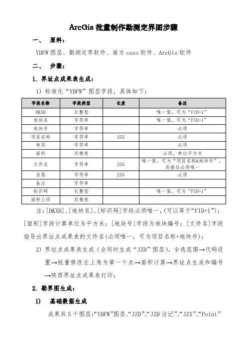
ArcGis批量制作勘测定界图步骤一、原料:YDFW图层、勘测定界软件、南方cass软件、ArcGis软件二、步骤:1.界址点成果表生成:1)标准化“YDFW”图层字段,具体如下:注:[DKXH]、[地块名]、[标识码]字段必须唯一,(可以等于“FID+1”);[面积]字段计算单位为平方米;[地块号]字段为地块编号;[文件名]字段指导出界址点成果表的文件名(必须唯一,可为项目名称+地块号);2)界址点成果表生成(会同时生成“JZD”图层),全选范围→代码设置→批量修改左上角为第一个点→面积计算→界址点生成和编号→陕西界址点成果表打印;2.勘界图生成:1)基础数据生成“JZX”、“Point”“JZD注记”、成果共5个图层:“YDFW”图层、“JZD”、图层:a)符号化“YDFW”图层,线型宽度2、颜色(255,0,0);b)创建辅助图层(“Point”图层):为将“JZD”图层标注挤出宗地外,设置辅助图层,将“YDFW”图层转换为CAD文件,在CASS中将每个地块填充为旱地符号(比例尺1:500,保留范围线),将CAD中点图层导入ArcGis中,形成“Point”图层,并标注[color]字段为无色(冲突检测为“高”,勾选“放置压盖标注”,放置选择为“在点上放置标注”),点符号为无色,具体操作如下图:c)“JZD注记”图层生成,此步骤需要在b步骤完成后方可进行,标注 [JZDH] 字段,Times Roman 8号字体,字体宽度85,将“JZD注记”图层与“YDFW”图层进行关联,使“JZD注记”图层含有“YDFW”图层属性。
d)“JZX”图层,为标注两界址点距离,需创建此图层,将“YDFW”图层用“在折点处分割线”工具形成“JZX”图层,添加距离字段求取距离并保留两位小数,标注[距离]字段,再使用“Maplex标注引擎”设置放置属性,标注位置中选择“街道放置”,如下图:e)新建个人数据库将“YDFW”、“JZD”、“JZD注记”、“JZX”、“Point”图层加入数据库;2)成图a)制作好图框并添加动态文本(如四角坐标、图名等);位置动态文本内容左上X <dyn type="dataFrame" name="DataFrameName" property="upperLeft.x" units="kilometre" decimalPlaces="3"/>左上Y <dyn type="dataFrame" name="DataFrameName" property="upperLeft.Y" units="kilometre" decimalPlaces="3"/>右上X <dyn type="dataFrame" name="DataFrameName" property="upperRIGHTt.x" units="kilometre" decimalPlaces="3"/> 右上Y <dyn type="dataFrame" name="DataFrameName" property="upperRIGHT.Y" units="kilometre" decimalPlaces="3"/> 左下X <dyn type="dataFrame" name="DataFrameName" property="upperRIGHTt.x" units="kilometre" decimalPlaces="3"/> 左下Y <dyn type="dataFrame" name="DataFrameName" property="upperRIGHT.Y" units="kilometre" decimalPlaces="3"/> 右下X <dyn type="dataFrame" name="DataFrameName" property="upperLeft.Y" units="kilometre" decimalPlaces="3"/>右下Y <dyn type="dataFrame" name="DataFrameName" property="upperLeft.x" units="kilometre" decimalPlaces="3"/>图框如下(A4示例)粉色线框出均为动态文本,随属性自动变换;b)启用“数据驱动页”工具;c)设置数据驱动页→启用数据驱动页面→名称字段([地块号]字段,唯一值字段)→范围(勾选“居中并保持当前比例”)如下图,d)对“YDFW”图层、“JZD”图层“JZD注记”图层、“JZX”图层用[地块号]字段进行“自动定义查询”如下图:3)出图利用arcpy的.ExportToPNG函数批量导出图片,具体代码如下:mxd = arcpy.mapping.MapDocument("CURRENT")for pageNum in range(1, mxd.dataDrivenPages.pageCount + 1):mxd.dataDrivenPages.currentPageID = pageNumarcpy.mapping.ExportToPNG(mxd,r"C:\Users\Administrator\Desktop\22" + str(pageNum) + ".png",resolution="300",)原因:“YDFW”图层属性表 [shape*]字段值必须为二维面(即[shape*]字段值为“面”),部分CAD图层导出为三维面(即[shape*]字段值为“面ZM”)将图层“YDFW”转换为二维面,如下操作:。
arcgis界址点自动编号语句

arcgis界址点自动编号语句以下是一段使用ArcGIS Engine实现界址点自动编号的代码:```csharppublic static Response AutoNumber(int PartCount){PartCount = PartCount;ILayer mLayer = GetLayerByName("范围线");ILayer pLayer = GetLayerByName("界址点");if (mLayer != null){if (pLayer != null){string name = "";if (PartCount != 0){name = "下一部件";}if (MessageBox.Show("请拉框选择" + name + "开始编号的起点!", "提示", MessageBoxButtons.YesNo, rmation) == DialogResult.Yes) {operation = "选择编号起点";// 获取所有图层是否可选列表GetAllLayer(listLayer, Selectable);// 设置只有界址点图层可选IFeatureLayer pFeatureLayer = pLayer as IFeatureLayer;pFeatureLayer.Selectable = true;}else{operation = "";return new Response(Constant.Nothing, "");}}else{MessageBox.Show("请先加载界址点!", "提示", MessageBoxButtons.OK);}}else{MessageBox.Show("请先加载范围线!", "提示", MessageBoxButtons.OK);}return new Response(Constant.Success, "");}/// <summary>/// 地图点击事件/// </summary>/// <param name="sender">事件发送者</param>/// <param name="e">事件参数</param>private void aecMap_OnMouseDown(object sender, IMapControlEvents2_OnMouseDownEvent e){string operation = PageManager.operation;if (operation == "选择编号起点"){IEnvelope pEnv = MapControl.TrackRectangle();MapControl.Map.SelectByShape(pEnv, null, true);MapControl.Active。
arcgis开发常用源码

arcgis开发常⽤源码arcgis开发常⽤源码1.点上⽣成⾯的代码if (m_pFeatureLayer.FeatureClass.ShapeType == esriGeometryType.esriGeometryPolygon) { IPointCollection m_pPointCollection = new PolygonClass(); object missing = Type.Missing; int icount = newFeature.XLIST.Count; if (icount < 3) return; for (int i = 0; i < icount; i++) { IPoint point = new PointClass(); point.PutCoords(newFeature.XLIST, newFeature.YLIST); m_pPointCollection.AddPoint(point, ref missing, ref missing); } IPolygon m_pPolygon = m_pPointCollection as IPolygon; if (m_pPolygon == null) {System.Windows.Forms.MessageBox.Show("null"); return; } else { ITopologicalOperator pTopo = m_pPolygon as ITopologicalOperator; if (pTopo != null) { pTopo.Simplify(); } } IWorkspaceEdit m_pWorkspaceEdit = m_EngineEditor.EditWorkspace as IWorkspaceEdit;m_pWorkspaceEdit.StartEditOperation(); IFeature m_pFeature = m_pFeatureLayer.FeatureClass.CreateFeature(); m_pFeature.Shape = m_pPolygon as IGeometry; m_pFeature.Store(); m_pWorkspaceEdit.StopEditOperation(); }2.⽂件的打开保存另存的代码using System;using System.Windows.Forms;using ESRI.ArcGIS.esriSystem;using ESRI.ArcGIS.SystemUI;using ESRI.ArcGIS.Carto;namespace SaveMapDocument{/// <summary>/// Summary description for Form1./// </summary>public class SaveMapDocument : System.Windows.Forms.Form{public System.Windows.Forms.TextBox txtMapDocument;public System.Windows.Forms.Button cmdOpen;public System.Windows.Forms.Button cmdSave;public System.Windows.Forms.Button cmdSaveAs;private System.Windows.Forms.OpenFileDialog openFileDialog1;private System.Windows.Forms.SaveFileDialog saveFileDialog1;private IMapDocument m_MapDocument;private ESRI.ArcGIS.Controls.AxToolbarControl axToolbarControl1;private ESRI.ArcGIS.Controls.AxPageLayoutControl axPageLayoutControl1;private ESRI.ArcGIS.Controls.AxLicenseControl axLicenseControl1;private ESRI.ArcGIS.Controls.AxTOCControl axTOCControl1;/// <summary>/// Required designer variable./// </summary>private ponentModel.Container components = null;public SaveMapDocument(){//// Required for Windows Form Designer support//InitializeComponent();//// TODO: Add any constructor code after InitializeComponent call//}/// <summary>/// Clean up any resources being used./// </summary>protected override void Dispose( bool disposing ){//Release COM objectsSupport.AOUninitialize.Shutdown();if( disposing ){if (components != null){components.Dispose();}}base.Dispose( disposing );}#region Windows Form Designer generated code/// <summary>/// The main entry point for the application./// </summary>[STAThread]static void Main(){Application.Run(new SaveMapDocument());}private void Form1_Load(object sender, System.EventArgs e){//Add toolbar definitions to the ToolbarControlaxToolbarControl1.AddToolbarDef("esriControls.ControlsPageLayoutToolbar", -1, false, 0, esriCommandStyles.esriCommandStyleIconOnly);axToolbarControl1.AddToolbarDef("esriControls.ControlsGraphicElementToolbar", -1, true, 0,esriCommandStyles.esriCommandStyleIconOnly);//Set buddy controlaxToolbarControl1.SetBuddyControl(axPageLayoutControl1); axTOCControl1.SetBuddyControl(axPageLayoutControl1); cmdSave.Enabled = false;cmdSaveAs.Enabled = false;}private void cmdOpen_Click(object sender, System.EventArgs e){//Open a file dialog for opening map documentsopenFileDialog1.Title = "Open Map Document";openFileDialog1.Filter = "Map Documents (*.mxd)|*.mxd"; openFileDialog1.ShowDialog();// Exit if no map document is selectedstring sFilePath = openFileDialog1.FileName;if (sFilePath == ""){return;}//Open documentOpenDocument((sFilePath));if (cmdSave.Enabled == false){cmdSave.Enabled = true;}if (cmdSaveAs.Enabled == false){cmdSaveAs.Enabled = true;}}private void cmdSave_Click(object sender, System.EventArgs e){//Save changes to the current documentSaveDocument();}private void cmdSaveAs_Click(object sender, System.EventArgs e) 另存为{//Open a file dialog for saving map documentssaveFileDialog1.Title = "Save Map Document As";saveFileDialog1.Filter = "Map Documents (*.mxd)|*.mxd";saveFileDialog1.ShowDialog();//Exit if no map document is selectedstring sFilePath = saveFileDialog1.FileName;if (sFilePath == ""){return;}if (sFilePath == m_MapDocument.DocumentFilename){//Save changes to the current documentSaveDocument();}else{//SaveAs a new document with relative pathsm_MapDocument.SaveAs(sFilePath, true, true);//Open documentOpenDocument((sFilePath));MessageBox.Show("Document saved successfully!");}}private void OpenDocument(string sFilePath){if (m_MapDocument != null) m_MapDocument.Close();//Create a new map documentm_MapDocument = new MapDocumentClass();//Open the map document selectedm_MapDocument.Open(sFilePath,"");//Set the PageLayoutControl page layout to the map document page layout axPageLayoutControl1.PageLayout = m_MapDocument.PageLayout; txtMapDocument.Text = m_MapDocument.DocumentFilename;}private void SaveDocument(){//Check that the document is not read onlyif (m_MapDocument.get_IsReadOnly(m_MapDocument.DocumentFilename) == true) {MessageBox.Show("This map document is read only!");return;}//Save with the current relative path settingm_MapDocument.Save(m_esRelativePaths,true);MessageBox.Show("Changes saved successfully!");}}}3.访问⼀个地图static void OpenMXDViaMapDocument(string path){IMapDocument pMapDocument = new MapDocumentClass();if (pMapDocument.get_IsMapDocument(path)){pMapDocument.Open(path,null);IMap pMap;for (int i = 0; i <= pMapDocument.MapCount - 1; i++){pMap = pMapDocument.get_Map(i);Console.WriteLine();IEnumLayer pEnumLayer = pMap.get_Layers(null,true);pEnumLayer.Reset();ILayer pLayer = pEnumLayer.Next();while (pLayer != null){Console.WriteLine();pLayer = pEnumLayer.Next();}}}}4、地图坐标private void axMapControl1_OnMouseMove(object sender, IMapControlEvents2_OnMouseMoveEvent e) {string outx = null;string outy = null;IActiveView pActiveView = axMapControl1.ActiveView;BJAEINFunction.bj54tojingweiduAo(pActiveView, e.mapX, e.mapY, ref outx, ref outy);labelItem1.Text = "地理坐标:经度:" + outx + " 纬度:" + outy;//IFeatureLayer pFeatLyr;//pFeatLyr = axMapControl1.Map.get_Layer(2) as IFeatureLayer;//pFeatLyr.DisplayField = "⾯积";//pFeatLyr.ShowTips = true;//string pTips;//pTips = pFeatLyr.get_TipText(e.mapX, e.mapY, pActiveView.FullExtent.Width / 100);//toolTip1.SetToolTip(axMapControl1, pTips);}5、⼤地转北京54public static void bj54tojingweiduAo(IActiveView pActiveView, double inx, double iny, ref string outx, ref string outy) {try{IMap pMap = pActiveView.FocusMap;SpatialReferenceEnvironment pSpRE = new SpatialReferenceEnvironment(); IGeographicCoordinateSystem pGeoCS =pSpRE.CreateGeographicCoordinateSystem((int)esriSRGeoCSType.esriSRGeoCS_Beijing1954); ISpatialReference pSpr = pGeoCS;IPoint pPoint = new ESRI.ArcGIS.Geometry.Point();pPoint.X = inx;pPoint.Y = iny;IGeometry pGeo = pPoint;pGeo.SpatialReference = pMap.SpatialReference;pGeo.Project(pSpr);//坐标转换,由当前地图坐标转为北京54经纬度坐标double jwd_jd = pPoint.X;double jwd_wd = pPoint.Y;//转化成度、分、秒//经度int Jd, Wd, Jf, Wf;double temp;Single Jm, Wm;Jd = (int)jwd_jd; //度temp = (jwd_jd - Jd) * 60;Jf = (int)temp; //分temp = (temp - Jf) * 60;Jm = Convert.ToInt32(temp); //秒//纬度Wd = (int)jwd_wd; //度temp = (jwd_wd - Wd) * 60;Wf = (int)temp; //分temp = (temp - Wf) * 60;Wm = Convert.ToInt32(temp); //秒outx = Jd + "度" + Jf + "分" + Jm + "秒";outy = Wd + "度" + Wf + "分" + Wm + "秒";}catch (Exception ex){MessageBox.Show(ex.Message);}6.拖动代码private void btnClearSelction_Click(object sender, EventArgs e){ICommand pCommand = new ControlsMapIdentifyToolClass();ITool pTool = pCommand as ITool;switch (this.tabControl.SelectedTabIndex){case 0:pCommand.OnCreate(this.mainMapControl.Object);this.mainMapControl.CurrentTool = pTool;break;case 1:pCommand.OnCreate(this.axPageLayoutControl.Object);this.axPageLayoutControl.CurrentTool = pTool;break;}}7.axMapControl和axPagelayoutControl数据同步显⽰的程序 private void axMapControl1_OnMouseDown(object sender, IMapControlEvents2_OnMouseDownEvent e) { axMapControl1.MousePointer = esriControlsMousePointer.esriPointerCrosshair; IGeometry pGeom = axMapControl1.TrackRectangle(); DrawMapShape(pGeom);axMapControl1.CtlRefresh(esriViewDrawPhase.esriViewGeography, null, null); } private void DrawMapShape(IGeometry pGeom) { IRgbColor pColor; pColor = new RgbColorClass(); pColor.Red =100; pColor.Green =100; pColor.Blue =100; ISimpleFillSymbol pFillsyl; pFillsyl = new SimpleFillSymbolClass();pFillsyl.Color = pColor; object oFillsyl = pFillsyl; axMapControl1.DrawShape(pGeom, ref oFillsyl); } private void CopyAndOverwriteMap() { IObjectCopy objectCopy = new ObjectCopyClass(); object toCopyMap = axMapControl1.Map; object copiedMap =objectCopy.Copy(toCopyMap); object toOverwriteMap = axPageLayoutControl1.ActiveView.FocusMap; objectCopy.Overwrite(copiedMap, ref toOverwriteMap); } private void axMapControl1_OnAfterScreenDraw(object sender, IMapControlEvents2_OnAfterScreenDrawEvent e) { IActiveView activeView = (IActiveView)axPageLayoutControl1.ActiveView.FocusMap; IDisplayTransformation displayTransformation = activeView.ScreenDisplay.DisplayTransformation; displayTransformation.VisibleBounds = axMapControl1.Extent; axPageLayoutControl1.ActiveView.Refresh(); CopyAndOverwriteMap(); } private void axPageLayoutControl1_OnViewRefreshed(object sender, IPageLayoutControlEvents_OnViewRefreshedEvent e) { axTOCControl1.CtlUpdate(); CopyAndOverwriteMap(); }8.放⼤缩⼩放⼤ICommand pCommand = new ControlsMapZoomInToolClass(); ITool pTool = pCommand as ITool; pCommand.OnCreate(this.axMapControl1.Object); this.axMapControl1.CurrentTool = pTool;缩⼩ICommand pCommand = new ControlsMapZoomOutToolClass(); ITool pTool = pCommand as ITool; pCommand.OnCreate(this.axMapControl1.Object); this.axMapControl1.CurrentTool = pTool;9. 在arcsence中的各个控件的应⽤类似的arcmap也⼀样。
ARCGIS命令大全
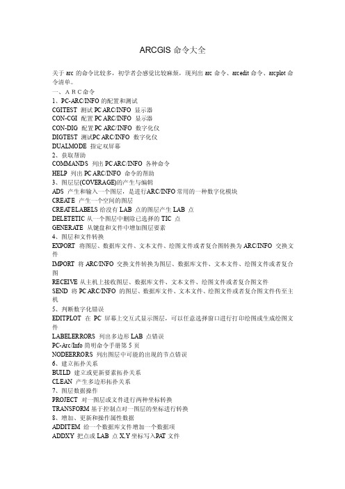
ARCGIS命令大全关于arc的命令比较多,初学者会感觉比较麻烦,现列出arc命令、arc edit命令、ar cplot命令清单。
一、ARC命令1、PC-A RC/INFO的配置和测试CG ITEST 测试PC ARC/INFO显示器CON-C GI 配置PC AR C/INFO显示器CON-DIG配置PC ARC/I NFO数字化仪DI GTEST 测试P C ARC/INF O 数字化仪DU ALMODE 指定双屏幕2、获取帮助COMMA NDS列出PCARC/INFO各种命令HEL P 列出PC AR C/INFO命令的帮助3、图层层(COVERAG E)的产生与编辑ADS 产生和输入一个图层,是进行A RC/INFO 常用的一种数字化模块CR EA TE产生一个空间的图层CREA TEL ABELS 给没有LAB 点的图层产生LAB 点D ELETETIC 从一个图层中删除已选择的TIC 点GE NERA TE从键盘和文件中增加图层要素4、图层和文件转换E XPORT将图层、数据库文件、文本文件、绘图文件或者复合图转换为ARC/INFO 交换文件IMPORT将ARC/INFO交换文件转换为图层、数据库文件、文本文件、绘图文件或者复合图REC EIVE 从主机上接收图层、数据库文件、文本文件、绘图文件或者复合图文件SEND 将PC ARC/INFO的图层、数据库文件、文本文件、绘图文件或者复合图文件传至主机5、判断数字化错误EDITPL OT在PC 屏幕上交互式显示图层,可以任意选择窗口进行打印绘图或生成绘图文件LABELERRO RS 列出多边形LA B 点错误PC-Arc/In fo 简明命令手册第5页NODE ERRORS列出图层中可能的出现的节点错误6、建立拓扑关系BU ILD 建立或更新要素拓扑关系CLE AN 产生多边形拓扑关系7、图层数据操作PR OJEC T 对一图层或文件进行两种坐标转换T RAN SFORM 基于控制点对一图层的坐标进行转换8、增加、更新和操作属性数据ADDITEM给一个数据库文件增加一个数据项AD DXY把点或LAB点X,Y坐标写入P A T 文件COP YIN FO 拷贝数据库文件DBASE在ARC 环境下启动dBASE (在装有dBASE 的情况下)DROP IT EM 从数据库文件中删去一个数据项I DEDIT更新图层中的US ER-IDJO INITEM基于相同的数据合并两个文件KILLI NFO 删除数据库文件TABLES启动TABLES程序9、图层管理APPEN D 合并图层(最多可多达100 个图层)CO PYC OV 拷贝图层COUNT 列出图层所有的要素个数DESCRIBE提供图层的各种信息FREQUEN CY列出图层中要素编码的频率I NDEX产生一个空间索引,以提高对图层要素查询的效率KILL删除一个图层LO ADANNO 拷贝一个名为[COVER].TXT 的数据库文件LIST CO VS 列出当前工作区的图层N ODEP OINT在含有弧段的节点中产生点图层PO INTDIST AN CE 计算指定半径范围内一个图层中点要素相对另一图层点要素的距离RENA MCOV 改变图层的名字TOL ERA NCE 设置或显示所用图层的容差(见“二、Arc Edit命令”中的“6、PC A rc Edit中的容差”)UNGEN从一个图层生成一个具有X,Y坐标的AS CII文件U NL OADANNO从图层数据库文件中拷贝注记10、图层显示ED ITPLOT在P C 屏幕上交互式显示图层,可以任意选择窗口进行打印绘图或生成绘图文件P LOTINFO 列出绘图文件信息RO TPLOT 从一个已生成的绘图文件按一定的旋转角度产生一个新的绘图文件11、ARC处理器命令CL EAR 清除PC显示器CLS 清除PC显示器CO LOR 改变显示屏对话窗线的颜色IN FODIREC TOR Y显示当前目录的数据库和数据文件I TEMS列出图层和数据文件的数据项定义LIST 列出图层和数据文件的值POPUP 弹出窗口和显示ASCAII文件QUIT退出ARC环境DEL ETE 删除磁盘文件DRA W 显示绘图文件、复合图文件等12、数据转换换(我国用户常用命令令)DEFARC将AutoCAD的A SCII绘图转换文件(DXF)转换为图层(COVERA GE)IGES ARC将原始图形交换标准文件(IG ES)转换为图层ARCDXF将图层(COVERA GE)转换为DXF文件ARCIGE S 将图层转换图形交换标准文件(IG ES)13、矢量量-栅格数据相互转换GRIDP OLY将一种栅格文件转换成多边形图层LINE GR ID 将线状图层转换成栅格文件P OINTGRID 将点状图层转换成栅格文件POLYG RI D 将多边形图层转换成栅格文件14、空间要素合并ID ENTI TY计算两个图层的几何交点。
一种界址表和界址点坐标成果表的自动生成方法

2 1 年第 1 0 1 期
・ 北京 测绘 ・
4 9
一
种界址表和 界址 点坐标 成果表 的 自动生 成方法
安 卫 王 文旭 宋 波 ( 津 市测 绘 院, 津 3 0 8 ) 天 天 0 3 1
[ 摘
要 ] 界 址 表 和 界 址 点 坐标 成 果 袁 是 地 籍 测绘 资 料 制 作 过 程 中 经 常要 绘 制 的 表格 ,然 而 很 多测 绘 单 位
图 2 界 址 线 扩展 属性 对 话 框
址 表及 界 址 点 坐 标 成 果 表 , 须 包 含 三 个 图层 , 别 必 分
22界址 表 和 界址 点 坐 标 成果 表 的样 式 . 界址 表 和 界址 点 坐标 成 果 表要 求 美 观 、大 方 , 使 读 者 一 r然 。 所有 的 界址 点 , 当 界址 线 , 宗地 都 有 属 性之 后 , 可生 成 特 定格 式 的 界址 表 和 界址 点 坐标 成 即
在地 籍 测 量 数据 的制 作 中 , 址 表 和界 址 点 坐 标 界
成 果 表 是 经 常 要 制 作 的 成 果 表 格 , 由 于 Mirsf coo t
果 表 的 自动 生 成 , 如 何 给界 址 点 、 址 线 、 故 界 宗地 添 加
扩 展 属性 这 里 就不 作 说 明 。 )
[ 稿 日期 】 2 1— 9 3 收 000—0
- 1、下载文档前请自行甄别文档内容的完整性,平台不提供额外的编辑、内容补充、找答案等附加服务。
- 2、"仅部分预览"的文档,不可在线预览部分如存在完整性等问题,可反馈申请退款(可完整预览的文档不适用该条件!)。
- 3、如文档侵犯您的权益,请联系客服反馈,我们会尽快为您处理(人工客服工作时间:9:00-18:30)。
在ArcGIS中生成界址点成果表可以通过以下步骤实现:
1. 打开ArcGIS软件,并加载需要生成界址点成果表的地理数据。
2. 在数据视图中,找到需要生成界址点成果表的数据层(通常为界址点图层),并将其设置为当前图层。
3. 打开“内容列表”窗口,并选择“表”选项卡。
4. 在“表”选项卡下,选择“添加表”功能,并设置表的数据源为当前界址点图层。
5. 根据需要,设置其他选项,如表名称、字段显示顺序等。
6. 点击“确定”按钮,等待ArcGIS生成界址点成果表。
7. 如果需要进一步编辑界址点成果表,可以使用ArcGIS中的表格编辑工具进行修改。
在代码方面,可以使用ArcGIS API for Python来自动化生成界址点成果表的代码。
以下是一个简单的示例代码,用于生成界址点成果表:
```python
import arcpy
from arcpy.sa import *
# 设置工作空间和数据层名称
workspace = "C:/data"
table_name = "Boundary_Points"
# 创建表格对象
table = arcpy.ListTables(table_name, workspace)[0]
# 获取表格中的所有字段名称
fields = [ for field in table.fields]
# 生成界址点成果表代码
code = ""
code += "// 界址点成果表代码\n\n"
code += "// 表格名称:{}".format(table_name) + "\n\n"
code += "// 字段列表:\n"
for field in fields:
code += "{} // {}".format(field, table.getFieldType(field)) + "\n"
code += "\n// 界址点数据...\n"
# 将代码写入文件
with open("ArcGIS_Output.txt", "w") as f:
f.write(code)
```
这段代码使用Python编写,通过ArcGIS API for Python的`arcpy`模块来获取表格中的所有字段名称,并生成一个包含字段列表的代码文件。
你可以根据需要修改代码中的字段名称和表
格名称,以适应你的实际情况。
在运行代码之前,请确保你已经安装了ArcGIS API for Python 和相关的Python库。