维亚思控制器蓝牙模块使用说明书
维亚思电瓶车控制器使用说明书
维亚思电瓶车控制器使用说明书摘要:1.维亚思电瓶车控制器的功能与特点2.控制器的安装与连接3.控制器的使用与操作4.控制器的维护与保养5.安全注意事项正文:一、维亚思电瓶车控制器的功能与特点维亚思电瓶车控制器是一款专为电瓶车设计的智能控制设备,具有以下功能与特点:1.节能环保:采用先进的电力驱动技术,使电瓶车的能耗降低,续航里程更长。
2.智能控制:具备过充保护、过放保护、欠压保护等功能,确保电瓶车的安全稳定运行。
3.无刷设计:采用无刷电机,降低了故障率,提高了电瓶车的使用寿命。
4.稳定可靠:采用优质的电子元件,保证控制器在各种恶劣环境下均能正常工作。
二、控制器的安装与连接1.控制器的安装位置应选择在通风、防水、防潮的环境中,以确保设备正常运行。
2.将控制器与电瓶、电机、充电器等设备正确连接,接线时注意线径与接线端子的匹配,确保连接牢固。
3.接线完成后,检查各个接线端子是否牢固,避免因接线松动导致的故障。
三、控制器的使用与操作1.开启电瓶车:将钥匙插入钥匙孔,旋转钥匙至“ON”位置,此时控制器开始工作。
2.速度调节:通过旋转调速器,可实现电瓶车速度的自由调节。
3.刹车系统:按下刹车把手,控制器将切断电机电源,使电瓶车停止运行。
4.倒车:将调速器切换至倒车模式,可实现电瓶车倒车行驶。
四、控制器的维护与保养1.定期检查控制器的接线端子,确保连接牢固,避免因接线松动导致的故障。
2.保持控制器清洁干燥,避免进水、油污等导致设备损坏。
3.长期不使用电瓶车时,需将控制器断电存放,以免损坏设备。
五、安全注意事项1.非专业人员请勿拆卸、维修控制器,以免造成设备损坏或人身伤害。
2.使用过程中,请遵守交通规则,确保行车安全。
LM400蓝牙模块一般性文档说明书

LM400 – Bluetooth Module GeneralThe LM400 is designed to provide Bluetooth 2.0 + EDR function on a small form factor. The Bluetooth function is based on CSR BlueCore4-Ext Bluetooth System, which implements the full speed class 1 Bluetooth operations with full 7 slave piconet support. The interface of LM400 to host system is UART.ContentsLM400 – B LUETOOTH M ODULE G ENERAL______1C ONTENTS________________________________________________1F EATURES_________________________________________________2A PPLICATION______________________________________________2B LOCK DIAGRAM__________________________________________________2E LECTRICAL C HARACTERISTICS______________________________3Absolute Maximum Ratings________________________________________3Recommended Operating Conditions________________________________3General Electrical Specifications____________________________________3R ADIO C HARACTERISTICS – B ASIC D ATA R ATE_________________________4Transmitter, VDD = 3.3 V, Temperature = + 20 °C______________________4Receiver, V DD =3.3 V Temperature = + 20 °C________________________5R ADIO C HARACTERISTICS – E NHANCED D ATA R ATE_____________________6Transmitter, VDD = 3.3 V Temperature = + 20 °C______________________6Receiver, VDD = 3.3 V, Temperature = + 20 °C________________________7H ARDWARE S TRUCTURE_____________________________________8PCB O VERWIEV__________________________________________________8D IMENSIONS_____________________________________________________8PCB___________________________________________________________8PCB Connector__________________________________________________8P IN A SSIGNMENT (PCB C ONNECTOR)__________________________________9R ESET B UTTON___________________________________________________9LED___________________________________________________________9P IN-OUT (MODULE)_______________________________________________10S CHEMATIC______________________________________________11C ONFIGURATION__________________________________________12F ACTORY S ETTINGS______________________________________________12AT C OMMAND S ET_______________________________________________12Features• Bluetooth Ver. 2.0 + EDR certification• Transmit Power up to +18dBm (class1)• Low current consumption:• Hold, Sniff, Park, Deep sleep mode• 3.0V to 3.6V operation• Full Bluetooth Data rate over UART and USB• Support up to 7 ACL l inks and 3 SCO links• Enhanced Data Rate (EDR) compliant for both 2Mbps and 3Mbps modulation modes• Interface: USB, UART & PCM (for voice codec)• SPP, HSP/HFP, HID, DUN firmware are available• Support for 802.1 1 Co Existence• RoHS Compliant• Small outline: 28.3 X 30.0 X2.8 mmApplication• Access point• Domestics and Industrial applications• Personal Digital Assistants (PDA)• Serial Adapter• GPS, PO S, Barcode Reader• Digital camera, Printer& Cellular phone• Cordless handsetBlock diagramElectrical CharacteristicsAbsolute Maximum RatingsStorage Temperature -40 °C +85 °CSupply Voltage (VDD) 2.7 VDC 3.6 VDCSupply Voltage (VCC) 3.0 VDC 3.3 VDCOther Pin Voltage Vss -0.4 VDC VDD +0.4 VDCRecommended Operating ConditionsTemperature -10 °C +70 °CSupply Voltage for UART 3.0 VDC 3.6 VDCSupply Voltage for USB 3.0 VDC 3.6 VDCGeneral Electrical SpecificationsCarrier Frequency 2.402 GHz - 2.480 GHz RF Output Power Measured in 50 Ω15 dBm 16.5 dBm 18 dBm RX sensitivity - -88 dBm -86 dBm Load Impedance No abnormal Oscillation - - 5:1 Input Low Voltage RESET, UART, GPIO, PCM -0.30 VDC - 0.80 VDC Input High Voltage RESET, UART, GPIO, PCM 0.7VDD - VDD+0.3 VDC Output Low Voltage UART, GPIO, PCM - - 0.4 VDC Output High Voltage UART, GPIO, PCM VDD-0.4 - - Average Current Consumption Receive DM1 - 114 mA -Radio Characteristics – Basic Data RateTransmitter, VDD = 3.3 V, Temperature = + 20 °C2.402 15 16.5 18dBm2.441 15 16.5 18 dBm RF transmit power 2.480 15 16.5 18 -6 to +20dBm2.402 - 12 25kHz 2.441 - 10 25kHz Initial carrier frequencytolerance2.480 - 9 25 ± 75 kHz2.402 - 890 1000kHz 2.441 - 870 1000 kHz -20dB bandwidth formodulated carrier2.480 - 820 1000 ≤ 1000kHz 2.402 - ± 10 ± 20kHz 2.441 - ± 10 ± 20 kHz Carrier Frequency Drift(single slot packet DH1)2.480 - ± 10 ± 20 ≤ 25kHz 2.402 - ± 10 ± 20kHz 2.441 - ± 10 ± 20 kHz Carrier Frequency Drift(five slot packet DH5)2.480 - ± 10 ± 20 ≤ 40kHz 2.402 - ± 7 ± 14kHz/50µs 2.441 - ± 7 ± 14 kHz/50µs Drift Rate 2.480 - ± 7 ± 14 ≤ 20kHz/50µs RF power control range16 25 - ≥ 16 dB2.402 145 165 170kHz 2.441 145 165 170kHz f1avg“Maximum Modulation ” 2.480 145 165 170 140< f1avg < 175 kHz2.402 115 150 -kHz 2.441 115 150 -kHz f2maz“Minimum Modulation ” 2.480 115 150 ->115 kHz Adjacent channel transmit power F = F 0 ± 2MHz - -35 -20 ≤ -20 dBm Adjacent channel transmit power F = F 0 ± 3MHz - -45 -40 ≤ -40 dBm Adjacent channel transmit power F > F 0 + 3MHz - -50 -40 ≤ -40 dBm Adjacent channel transmit power F < F 0 - 3MHz - -50 -40 ≤ -40dBmReceiver, V DD =3.3 V Temperature = + 20 °C2.402 - -88 -86dBm 2.441 - -88 -86dBm Sensitivity at 0.1% BER(Single slot packets)2.480 - -88 -86 ≤ -70 dBm2.402 - -88 -86dBm 2.441 - -88 -86 dBm Sensitivity at 0.1% BER(Multi slot packets )2.480 - -88 -86 ≤ -70dBm2.402 - -20 -10dBm 2.441 - -20 -10 dBm Maximum received signal levelat 0.1% BER2.480 - -20 -10≥ -20dBm C/I co-channel - 6 11 < 11 dB - 6 11 ≤ 11 dBm Adjacent channel selectivity C/I F = F 0 + 1 MHz - -4 - ≤ 0 dBm Adjacent channel selectivity C/I F = F 0 - 1 MHz - -4 - ≤ 0 dBm Adjacent channel selectivity C/I F = F 0 + 2 MHz - -38 - ≤ -30 dBm Adjacent channel selectivity C/I F = F 0 - 2 MHz - -23 - ≤ -20 dBm Adjacent channel selectivity C/I F > =F 0 + 3 MHz - -45 - ≤ -40 dBm Adjacent channel selectivity C/I F <= F 0 - 5 MHz - -44 - ≤ -40 dBm Adjacent channel selectivity C/I F =F image - -22 - ≤ -9 dBm F 0 = 2441 MHzMaximum level of intermodulation interference (n = 5)- -30 - ≥ -39 dBmRadio Characteristics – Enhanced Data RateTransmitter, VDD = 3.3 V Temperature = + 20 °C2.402 - 6 -dBm2.441 - 6 -dBm Maximum RF transmit power 12.480 - 7 --6 to +20 dBm Relative transmit power - -1.6 - -4 to +1dB π /4 DQ PSKMaximum carrier frequency stability w 0 - 2 - ≤ ±10 for all blocks kHz π /4 DQ PSKMaximum carrier frequency stability w i - 6 - ≤ ±75 for all packets kHz π /4 DQ PSKMaximum carrier frequency stability | w 0 + w i | - 8 - ≤ ±75 for all blocks kHz 8 DPSKMaximum carrier frequency stability w 0 - 2 - ≤ ±10 for all blocks kHz 8 DPSKMaximum carrier frequency stability w i - 6 -≤ ±75 for all packets kHz 8 DPSKMaximum carrier frequency stability | w 0 + w i |- 8 -≤ ±75 for all blocks kHz RMS DVEM - 7 - ≤ 20 dBm 99% DEVM - 13 - ≤ 30 dBm π /4 DQ PSKModulation Accuracy Peak DEVM - 19 - ≤ 35 dBm RMS DVEM - 7 - ≤ 13 dBm 99% DEVM - 13 - ≤ 20 dBm 8 DPSKModulation AccuracyPeak DEVM - 17- ≤ 25 dBm F> F 0 +3 MHz -<-50 - ≤ -40 dBm F< F 0 -3 MHz -<-50 - ≤ -40 dBm F= F 0 -3 MHz --46 - ≤ -40 dBm F= F 0 -2 MHz --34 -≤ -20 dBm F= F 0-1 MHz - -35-≤ -26 dBm F= F 0+1 MHz - -35-≤ -26 dBm F= F 0+2 MHz --31 - ≤ -20 dBm In-band spurious emissionsF= F 0+3 MHz--33 - ≤ -40 dBm EDR Differential Phase Encoding- No Errors-≥ 99%1Note :Measurement made using a POWER_TABLE entery of TX_PRE 80, INT PA63, EXT PA255. This ensures that the Bluetooth requirements for ACP and those defined by the FCC and ETSI are satisfied over the operating temperature range of -5°C to + 45°C. Although the design is capable of generating in excess of + 18dBm, regulatory compliance over the full temperature range of -5°C to + 45°C will not be satisfied if the transmit power approaches this value.Receiver, VDD = 3.3 V, Temperature = + 20 °Cπ /4 DQ PSK- -87 - dBm Sensitivity at 0.1% BER 8 DPSK - -78 -≤ -70dBmπ /4 DQ PSK- -8 - dBm Maximum received signal level 8 DPSK - -10 -≥ -20dBm π /4 DQ PSK - 10 - ≤ +13dBm C/I co-channel at 0.1% BER8 DPSK - 19 - ≤ +21dBm π /4 DQ PSK - -10 - ≤ 0dB Adjacent channel selectivity C/I F = F 0 + 1 MHz 8 DPSK - -5 - ≤ +5dB π /4 DQ PSK - -11 - ≤ 0dB Adjacent channel selectivity C/I F = F 0 - 1 MHz 8 DPSK - -5 - ≤ +5dB π /4 DQ PSK - -40 - ≤ -30dB Adjacent channel selectivity C/I F = F 0 + 2 MHz 8 DPSK - -40 - ≤ -25dB π /4 DQ PSK - -23 - ≤ -20dB Adjacent channel selectivity C/I F = F 0 - 2 MHz 8 DPSK - -20 - ≤ -13dB π /4 DQ PSK - -45 - ≤ -40dB Adjacent channel selectivity C/I F > =F 0 + 3 MHz 8 DPSK - -45 - ≤ -33dB π /4 DQ PSK - -45 - ≤ -40dB Adjacent channel selectivity C/I F <= F 0 - 5 MHz 8 DPSK - -45 - ≤ -33 dB F 0 = 2405, 2441, 2477 MHzπ /4 DQ PSK - -20 - ≤ -7dB Adjacent channel selectivity C/I F =F image 8 DPSK - -15 - ≤ 0dBHardware StructurePCB Overwiev DimensionsPCBUnit: mmPCB ConnectorUnit: mmPin Assignment (PCB Connector)Direction Description Signal Level1 GND Power Ground Ground2 TXD Output UART Data Out TTL3 RXD Input UART Data Input TTL4 RTS Output UART Ready to Send TTL5 CTS Input UART Clear to Send TTL6 VDD Input DC Input (3.0–3.3 V) Power7 Data led** Input Data Transfer (Active Low) TTLSpecified TTL8 Status* Output Not9 DSR* Input Data Set Ready TTL10 DTR* Output Data Terminal Ready TTL11 RST Input Reset (Active Low) TTL12 GND Power Ground Ground* = Not in use** = Indicates transmitting/receiving data over an established Bluetooth connectionReset ButtonBy pressing the Reset button you can• disconnect and reconnect a wireless connection (short press)• restore the default Baud Rate, 19 200 bps (> 3 s press)LEDThe LED indicates when a Bluetooth connection is established.Pin-out (module)1 GND GND Common ground2 PVCC Power Power Amp. Power Supply (3.3V)3 AIO (0) Bi -directional Programmable I/O terminal , 32KHz sleep clock input4 AIO (1) Bi -directional Programmable I/O terminal5 PIO (0) Bi -directional Programmable I/O terminal , RX Enable6 PIO (1) Bi -directional Programmable I/O terminal , TX Enable7 PIO (2) Bi -directional Programmable I/O terminal , USB_PULL_UP , CLK_REQ_OUT8 PIO (3) Bi -directional Programmable I/O terminal , USB_WAK E_UP , CLK_REQ_IN9 PIO (4) Bi -directional Programmable I/O terminal , USB_O N , BT_Priority/Ch_Clk output for co-existence signalling10 GND GND Common ground11 PIO (5) Bi -directional Programmable I/O terminal , USB_DETAC H , BT_Active output for co-existence signalling12 PIO (6) Bi -directional Programmable I/O terminal , CLK_REQ ,WLAN_Active/Ch_Data input for for co-existence signalling13 PIO (7) Bi -directional Programmable I/O terminal14 PIO (8) Bi -directional Programmable I/O terminal15 PIO (9) Bi -directional Programmable I/O terminal16 RESET CMOS input Reset input of module, Active low reset17 VCC Power Module power supply input18 GND GND Common ground19 GND GND Common ground20 USB_DP Bi-directional USB data plus21 USB_DN Bi-directional USB data minus22 PCM_SYNC Bi-directional Synchronous data sync23 PCM_IN CMOS input Synchronous data input24 PCM_OUT CMOS output Synchronous data output25 PCM_C LK Bi -directional Synchronous data clock26 UART_RX CMOS input UART data input27 UART_TX CMOS output UART data output28 UART_RTS CMOS output UART request to send (active low)29 GND GND Common ground30 UART_CTS CMOS input UART clear to send (active low)31 SPI_MOSI CMOS input Serial Peripheral Interface data input32 SPI_CSB CMOS input Chip select for Synchronous Serial Interface (active low)33 SPI_CLK CMOS input Serial Peripheral Interface clock34 SPI_MISO CMOS output Serial Peripheral Interface data output35 PIO (11) Bi-directional Programmable I/O terminal36 PIO (10) Bi-directional Programmable I/O terminal37 RF_IO Analogue Antenna interface38 GND GND Common groundSchematicConfigurationYou can reprogram the default settings on the module using AT commands (see section below AT Command Set) or the Wireless Bluetooth Configuration Utility firmware (see separate manual).Factory Settings• Baud rate: 19 200 bps• Data bit: 8• Parity: None• Stop bit: 1• Flow control: HW• Others: See section AT Command SetAT Command SetThe following is the AT command set for the module in the command mode (that is, when the module is in the disconnection state).The commands will be preceded by “AT” to be executed. (Ex: To execute the address inquiry, “B?”, use “ATB?”)All the commands and parameters are case insensitive.+++ Escape sequence with guard time. When the device is in Data mode, it can be forced back into Command mode while maintaining the connection to the remote device. The characters should then be sent 1 second apart.A This command is used to establish a connection.Available only when the adapter is in the master role.A Connect the adapter to a specified Bluetooth device. Available only when “ATD=xxxxxxxxxxxx” is executed.A1-A8 Connect the adapter to a Bluetooth device in the neighborhood found through “ATF?”B This command is used to display the Bluetooth address of the local adapter.B? Inquire the Bluetooth address of the local adapter.C This command enable or disable flow control signals (CTS/RTS) of theUART port.C0 Disable flow control.(default) C1Enable flow control.C? Inquiry of current setting.D For security purpose, this command is used to specify a unique remoteBluetooth device to be connected.In the master role, the adapter pairs and connects with the designatedremote slave address.If the adapter is in the slave mode, this command is a filter condition toaccept the inquiry of the master device.D=xxxxxxxxxxxx "xxxx-xx-xxxxxx" is a string of 12 hexadecimal digits.D0 Restore the status in which the adapter can connect with any remote address.D? Inquiry the designated address that can be paired and connected.E This command is used to specify whether the adapter echoes charactersreceived from the UART back to the DTE/DCE.E0 Command characters received from the UART are not echoed back to the DTE/DCE.(default) E1Command characters received from the UART are echoed back to theDTE/DCE.E? Inquire the current setting.F This command is used to search for any Bluetooth device in theneighborhood within one minute. If any device is found, its name andaddress will be listed. The search ends with a message “Inquiry ends. Xxdevice(s) found.”Available only when the adapter is in the master role and manuallyconnected (see command “O”).F? Inquire Bluetooth devices in the neighborhood.H This command can drop the connection either in master or slave role. It isalso used to specify whether the adapter can be discovered or connected byremote devices.H Drop current connection.H0 The adapter enters the undiscoverable mode. If a pair has been made, the original connection can be resumed. But other remote master device cannot discover this adapter. Reboots when set.(default) H1The adapter enters the discoverable mode. Reboots when set.H? Inquire the current setting.I This command is used to inquire the firmware version and other settings.I0 Inquire the version codes.I1 Inquire all current settings.I2 Inquire status on RSSI at Online Command Mode.K This command is used to specify number stop bits of COM port.(default) K0 One stop bit.K1 Two stop bits.K? Inquire the current setting.L This command is used to specify the baud rate of COM port.L0 4800 bpsL1 9600 bps(default) L2 19200 bpsL3 38400 bpsL4 57600 bpsL5 115.2 kbpsL6 230.4 kbpsL? Inquire the current baud rate.M This command is used to specify parity bit setting of COM port.(default) M0 None parity bit.M1 Odd parity.M2 Even parity.M? Inquire the current setting.N This command is used to specify a name for the adapter.You can specify a friendly name using 0 to 9, A to Z, a to z, space and -,which are all valid characters. Note that “space” and “-” are not permittedfirst or last in the name. The default name is “Serial Adaptor”.N=xxxxxx "xxxxxx" is a character string with a maximal length of 16.N? Inquire the name of the local adapter.O This command directs the device to switch from Command mode to Online data mode. It is also used enable/disable auto-connection feature (availableonly when the adapter is in the master role).O Switch from Command mode to Online Data mode.(default) O0 Automatically connect the adapter to a device specified by “ATD”, or any available device if “ATD” is not executed. Reboots when set.O1 Disable auto-connection feature. After it is executed, you need to execute “ATA” to manually connect a remote device. Reboots when set.O? Inquire the current setting.P This command is used to specify a PIN. The default PIN is “1234". Paired adapters should have a same PIN.P=xxxx "xxxx" is a 4–8-digit string.P0 Cancel authentication by PIN.P? Inquire the current PIN.Q The command is used to set if result messages are prompted when ATcommands are executed.The result messages are: OK/ERROR for command execution, orCONNECT/DISCONNECT for connection status.(default) Q0Result messages are prompted.Q1 Result messages are not prompted.Q? Inquire the current setting.This command is used to specify whether the adapter is in the master or Rslave role.If the device role is changed, the adapter will reboot and all pairedaddresses will be cleared.R0 Set the adapter to the master role.(default) R1Set the adapter to the slave role.R? Inquire the current role of the adapter.S This command is used to enable/disable auto-power saving feature ofRS232 driver.S0 Disable RS232 force on (auto power down) mode.(default) S1Enable RS232 force on (auto power down) mode.S? Inquiry of current setting.X Disable/Enable escape sequence (+++).X0 Disable escape sequence.(default) X1Enable escape sequence.X? Inquiry of current setting.Z This command is used to restore the default settings andoriginate a warm start.Z0 Restore the default settings.。
维亚思控制器蓝牙模块使用说明书

维亚思控制器蓝牙模块使用说明书摘要:一、维亚思控制器蓝牙模块简介二、蓝牙模块安装与配置三、蓝牙模块使用方法与技巧四、常见问题与解决方案五、注意事项与售后服务正文:一、维亚思控制器蓝牙模块简介维亚思控制器蓝牙模块是一款高性能、稳定可靠的蓝牙通信设备,广泛应用于各种智能控制系统中。
该模块具备蓝牙4.0和5.0双版本,支持低功耗、长距离、高速传输等特性,能够满足各类场景的需求。
通过该模块,用户可以方便地将控制器与手机、平板等智能设备进行连接,实现远程控制、数据传输等功能。
二、蓝牙模块安装与配置1.安装:在安装维亚思控制器蓝牙模块之前,请确保设备已关闭电源,并根据产品说明书进行正确的接线。
将蓝牙模块接入控制器的相应接口,然后开启设备电源。
2.配置:使用手机或其他智能设备的蓝牙功能,搜索附近可用的蓝牙设备。
找到维亚思控制器蓝牙模块的蓝牙名称,并连接。
连接成功后,可在手机上进行相关设置,如配对密码、权限管理等。
三、蓝牙模块使用方法与技巧1.远程控制:连接成功后,用户可以通过手机等智能设备对控制器进行远程操作,如开关、调节参数等。
2.数据传输:维亚思控制器蓝牙模块支持数据传输功能,可以实现设备间的数据同步。
例如,将手机上的图片、音乐等文件传输至控制器,进行展示或播放。
3.技巧:在实际使用过程中,用户可通过更改蓝牙名称、配对密码等方法,提高蓝牙连接的安全性和稳定性。
四、常见问题与解决方案1.连接不上:请检查设备是否开启蓝牙功能,或重新启动设备尝试连接。
2.连接不稳定:调整设备距离,或更改蓝牙名称、配对密码。
3.数据传输失败:请检查文件格式是否支持,或重新尝试传输。
五、注意事项与售后服务1.请勿将维亚思控制器蓝牙模块置于潮湿、高温、灰尘密集的环境中,以免影响使用寿命。
2.在使用过程中,如遇到问题,请及时联系售后服务人员。
蓝牙SPS模块用户手册说明书

BLE SPS Module User Manual V1.12014.6Revision HistoryCatalog1Overview (4)2Module Package (6)3Factory settings (6)4Data transmit and Command Set (7)5The format of command setting (8)5.1Switch to the Slave(Peripheral) role (8)5.2Switch to the Master(Central)role (8)5.3Modify the baud rate (8)5.4Set the address of the target module (8)5.5Set the advertising interval value (9)5.6Set connection parameters (9)5.7Set the module name (10)6View Parameters command (10)6.1View Current role of module (10)6.2View the Baud Rate of Module (10)6.3View the target module BT address (11)6.4View the BT address of the module (11)6.5View the name of module (11)6.6View the advertising interval value of module (11)6.7View the connection parameters. (11)7Program Example (12)8Test Tool (12)8.1PC software test tool (12)8.1Test the Data Passthrough Between module and module. (16)8.2Test Data Passthrough in Smartphone (17)8.2.1Use “LightBlue” APP for Testing (17)8.2.2Use the APP testing that WeBee provide(ios7.0 above) (25)1OverviewDescription:The BLE module is designed with TI CC2540/CC2541 that is a Bluetooth low energy chip which is compliant Bluetooth 4.0 single-mode. It is mainly used in low-power sensor networks and short-range wireless communication. The basic function of WB-BLE-001 is to transmit data between WB-BLE-001 module and WB-BLE-001 module or WB-BLE-001 module and smart phone.WB-BLE-001 integrate s with the “AT” command set. So the module can set in master role or slave role, the name of the module can be modified, the baud rate, advertising interval value and the connection parameters can be modified by users. Feature:Small size2.2*1.5 cmLong communication distance Smart phone to Module:60meters;Module to Module :100meters(In open environment)Optimize the BLE stack in depth,Works Power Consumption:60 ~ 800uA;Master and slave can be switchA serial port for sending interval <10msRespond time from sleep less than 0.4STransmit speed 3~5Kb/sIntegrate AT command setSupport Android 4.3 、IOS、PCNo need MFIWeBee Provide:PC software for Modify and view the relate parametersAPP Test SoftwareProfessional technical guidanceSupport enterprise, individual additional customization2Module PackageFigure 2.1 Module Package 3Factory settings4Data transmit and Command SetThe pin that the module used are as follow:When the pin P0_0 pull up as high level and at this time the pin P0_1 also pull up as high level, then the module works in transmit data mode.When the pin P0_0 pull up as high level and at this time the pin P0_1 pull down as low level, then the module works in command setting mode.When both P0_0 and P0_1 are pulled down as low level, then the module works in sleep mode.Note:1.Pin P0_0 can be connected to a pull-up resistor to 3.3V, if the Users don’t needthe sleep mode.2.Pin P0_1 can be connected to a pull-up resistor to3.3v, if the Users don’t needthe command setting mode.3.WeBee can help custom to modify the firmware for the special application.5The format of command settingAll the command format is consist of ”FA+type+data length+data+AA”, the head of the command frame is FA, type is the command type, data length is the length of user data in this frame, AA is the finish symbol of the command frame.5.1Switch to the Slave(Peripheral) roleThe default role of module is slave role. As slave role, it can communication with the smart phone and also the master role module.The command is: FA 00 00 AAIf executed successful, the module will return “Set Peripheral Role OK\n”immediately. Otherwise it means it set failed.5.2Switch to the Master(Central)roleAs the master role, the module only communicates with the slave module.The command is: FA 01 00 AAIf executed successful, the module will return “Set Central role OK\n” immediately. Otherwise it means it set failed.5.3Modify the baud rateThe module can compatible with a variety of baud rate.Otherwise it means it set failed.5.4Set the address of the target moduleWhen the module is in master role, it is need to set the master module connectwhich slave module.The command is: FA 03 06 XX XX XX XX XX XX AA;“XX XX XX XX XX XX” This 6 bytes is the target slave module address.If executed successful, the module will return "Set target address ok\n" immediately. Otherwise it means it set failed.Note: When the target slave module address is set as “00 00 00 00 00 00”, it means the master will connect the target slave module which the master first scanned. The factory setting is the “00 00 00 00 00 00”.5.5Set the advertising interval valueWhen the module is slave role, it may need to set the advertising interval value.The command is: FA 04 length interval AAFor example if want to set advertising interval value in 500ms, so the 500/0.625=800. Then turns the 800 into Hexadecimal: 800(d) = 320(h)Then 320 is the 03 and 20, so the Command is FA 04 02 03 20 AA.If executed successful, the module will return "Set Advertising interval OK\n" immediately. Otherwise it means it set failed.5.6Set connection parametersThe connection parameters influence the data transmit speed and the power consumption.The command is: FA 05 08 conn_min conn_max latency timeout AAThere are 4 variables, every variable is 2 bytes.For example if the conn_min set as 6,conn_max set as 150latency set as 0timeout set as 300Then the final command is : FA 05 08 00 06 00 96 00 00 01 2C AAIf executed successful, the module will return "Set Connection Interval OK\n" immediately. Otherwise it means it set failed.Note: The small of the connection interval, the speed is faster and the power consumption is higher.conn_min and conn_max (In 1.25 ms unit, range: 7.5 ms to 4 s (0x0006 - 0x0C80)) Latency (Range 0-499)Timeout (In 10ms unit,Range: 100ms to 32 seconds (0x000a - 0x0c80).)5.7Set the module nameWhen the module in slave role, use the following command can set the advertising name.Command: FA 06 name_length name AAFor example the name of module is set in ”123”,then the command is FA 06 03 31 32 33 AAIf executed successful, the module will return "Set Name OK\n"immediately. Otherwise it means it set failed.Note: The length of module name less than 21 bytes.6View Parameters commandWB-BLE-001 module provides the interface to view the module parameters. The current role of the module, baud rate of the module, advertising interval value of module, connection interval value of module and the name of the module can be viewed.The view command format is: ”FB+type+00+AA”6.1View Current role of moduleView the current role of the module, the command is following:FB 00 00 AAIf executed successful, the UART of the module will return as follow:When module is Peripheral role: print “ Peripheral Role”When module is Central role: print “Central Role”.6.2V iew the Baud Rate of ModuleView the Baud Rate of the module, the follow command is provided: FB 01 00 AAIf executed successful, the UART of module will print: "Baudrate is: 9600", that meas the baud rate of module is 9600bps.6.3View the target module BT addressWhen the module is in central role, it can be view the BT address of target module that the central module will connect. The command is as follow:FB 02 00 AAIf execute successful, the UART of module will print:Target Address:xxxxxxxxxxxx,xxxxxxxxxxxx is the target peripheral BT address.6.4View the BT address of the moduleEvery module has itself BT address, the following command can get the local module BT address:FB 03 00 AAIf execute successful, the UART of module will print: Local Address:xxxxxxxxxxxx6.5View the name of moduleThe name of module can be got by smart phone when the module is in peripheral role. Also can be got by UART. The following command can get:FB 04 00 AAthe UART of module will print the name of the modle.6.6View the advertising interval value of moduleUsing the following command can get the advertising interval value of module:FB 05 00 AA,If execute successful, the UART of module will print the advertising interval value. 6.7View the connection parameters.The following command can get the connection parameters:FB 06 00 AAIf execute successful, the UART of module will print the connection parameters.7Program ExampleThe external MCU sends the data to the module, the external MCU firstly must pull up the P0_0 pin the module in order in wake up the module. When finish sending data, the external MCU must bt pull down the P0_0 pin of the module.Void sendDataViaBt(unint8 *buf,uint8 len){P0_0=1 //Wake ukDelay_10us();Uart_send(buf,len);Delay_1ms();P0_0=0; //Make the module into sleep for saving power}8Test Tool8.1PC software test tool1.After installed the PC BLE software, the following picture will show.2.C lick the “Serial Configure” and input the baud rate value3.Click the “OK” to open the UART of PC.4.Here provide “View the module role” for example. Other test, the users can do byyourself.From the Part4, If send the command to the module must Pull Down the P1_0 pin. If uses WeBee Board, Pressed the S2 Key and click the “Module role” in the “View Command set”.It shows the current role is “Central”N ote: Users can do this by “UART Assistant” software without WeBee software.8.1Test the Data Passthrough Between module and module. Power on the module, When the LED1 is on that means this 2 modules is connected.Then open the “UART Assistant” software and set the UART number and baud rate. Then this to module can transmit data to each other.8.2Test Data Passthrough in SmartphoneThe smartphone can only communication with the Peripheral role module.8.2.1Use “LightBlue” APP for Testing.1.Download the ”LightBlue” app in apple app store and install it.2.Module connects to the PC via USB and Power on it. At this time, the lightbluewill found the “BLE SPS” the listed it. As the following shows.3.Click the “BLE SPS”, the smart phone will connect to the module and the LED1 ofthe board will be on. The following picture means the connection is built.4.Click “ 0xFEE0”, it will show“0xFEE1” and click “0xFEE1”,it will show the followingpicture:5.Click “Write” will send the data from smartphone to module.6.T he module gets the data from the smartphone will show in “UART Assistant”software.7.Now make the module sends data to smartphone:C lick “start notify” in the following picture.8.PC software S ends “123” to Module via UART9.T he smartphone will get the data “123” from the module. It shows as following:8.2.2Use the APP testing that WeBee provide(ios7.0 above) 10.Download the ”BLE SPS” app in apple app store and install it.1.Connect the module to PC via USB. Click “Scan Ble Device”b2.The app will list the device, when it has scan the BLE Module, Device name is:“BLE SPS”, Choose “BLE SPS” to be connected.3.After the connection is built, they can transmit data to each other.。
STEVAL-IDB003V1 Bluetooth Smart Platform 快速入门指南说明书

UM1789User manualSTEVAL-IDB003V1 evaluation boardquick start guideIntroductionThe STEVAL-IDB003V1 is an evaluation board based on BlueNRG, a low power Bluetooth®Smart IC that is compliant with the Bluetooth® v4.0 specification and supports both masterand slave roles.The STEVAL-IDB003V1 platform features an on-board STM32L low power microcontroller.It can be used to explore the BlueNRG features and as a development platform forBluetooth® Smart applications running on the STM32L microcontroller and interfacing to theBlueNRG network coprocessor.Figure 1. STEVAL-IDB003V1 Bluetooth® Smart platform*63* 6*September 2014DocID026531 Rev 11/10Contents UM1789 Contents1Getting started . . . . . . . . . . . . . . . . . . . . . . . . . . . . . . . . . . . . . . . . . . . . . . 31.1Install BlueNRG DK SW package . . . . . . . . . . . . . . . . . . . . . . . . . . . . . . . 31.2Insert the STEVAL-IDB003V1 board . . . . . . . . . . . . . . . . . . . . . . . . . . . . . 31.3Open the BlueNRG GUI . . . . . . . . . . . . . . . . . . . . . . . . . . . . . . . . . . . . . . . 4 2SW demonstration applications . . . . . . . . . . . . . . . . . . . . . . . . . . . . . . . . 6 3References . . . . . . . . . . . . . . . . . . . . . . . . . . . . . . . . . . . . . . . . . . . . . . . . . 7 4List of acronyms . . . . . . . . . . . . . . . . . . . . . . . . . . . . . . . . . . . . . . . . . . . . 8 5Revision history . . . . . . . . . . . . . . . . . . . . . . . . . . . . . . . . . . . . . . . . . . . . 92/10DocID026531 Rev 1UM1789Getting started 1 Getting startedThe STEVAL-IDB003V1 evaluation board is preprogrammed with a software(BlueNRG_VOM_x_x.hex) allowing users to run the BlueNRG PC GUI (graphical userinterface), which can be used to interact and evaluate the capabilities of the BlueNRGnetwork processor.To configure the STEVAL-IDB003V1 platform and run the preprogrammed software andassociated BlueNRG GUI, follow the instructions below.1.1 Install BlueNRG DK SW package•Before using the STEVAL-IDB003V1 platform, download the latest BlueNRG DK software package available on the STEVAL-IDB003V1 web page (Table1, STEVAL-IDB003V1platform)•Unzip the file, launch the related installer and follow installation steps (default installation path is C:\Program Files (x86)\STMicroelectronics\BlueNRG DK x.x.x)•Wait for the package installation to complete.The following folder will be available on the selected installation path.Figure 2. BlueNRG DK SW package structure and content*63* 6* The software package installation procedure will also automatically install the following PCsoftware drivers available in the PCDriver folder:•USB DFU PC driver required for supporting device firmware upgrade (DFU) through USB•USB Virtual COM Port driver required for supporting the USB Virtual COM I/O communication channels.1.2 Insert the STEVAL-IDB003V1 board•Plug the STEVAL-IDB003V1 into a PC USB port: Windows’ new hardware wizard will appear.•Wait for the device recognition process to complete: in Computer, Manage, Device Manager, Ports (COM & LPT area), a new STMicroelectronics Virtual COM Port willappear.DocID026531 Rev 13/10Getting startedUM17894/10DocID026531 Rev 1Figure 3. STEVAL-IDB003V1 Virtual COM Port1.3 Open the BlueNRG GUIThe BlueNRG GUI is available in the BlueNRG DK software package, Application folder (Figure 2: BlueNRG DK SW package structure and content ):•Launch the BLUENRG_GUI.exe file•Select the COMxx port associated to the STEVAL-IDB003V1 platform •Click on Open tab: the BlueNRG GUI is now ready to use*63* 6*DocID026531 Rev 15/10UM1789Getting startedFigure 4. BlueNRG GUIThe BlueNRG GUI utility can send standard and vendor-specific HCI commands to the BlueNRG network coprocessor and receive events from it. It allows the user to configure each field of the HCI command packets to be sent and analyze all received packets.Note:For more information on the BlueNRG GUI capabilities and available utilities, refer to Table 1 (UM1686 user manual).GSPG1006141045SGSW demonstration applications UM1789 2 SW demonstration applicationsIn order to develop a software application for the STEVAL-IDB003V1 platform, it isrecommend to start with the reference demonstration applications provided within theBlueNRG DK software package, in the Projects folder (Figure2). The IAR EmbeddedWorkbench for ARM (EWARM) tool V6.60 is needed to build software applications runningon the STM32L microcontroller.Pre-built STM32L microcontroller binary images for the reference demonstrations arealready available in the BlueNRG DK software package, in the Firmware folder (Figure2).To download an STM32L binary image, apply the following DFU procedure:•Open the BlueNRG GUI•Press and hold the STEVAL-IDB003V1 platform SW1 button•Plug the STEVAL-IDB003V1 board into a PC USB port–The orange LED D3 will start to blink: STM32L device is in DFU mode, allowing it to upgrade its Flash image through USB interface.•From the BlueNRG GUI, select Tools, Flash Motherboard FW and follow the indications to select the new binary application image to be downloaded into the STM32L Flash.•Wait for the DFU download process to complete.Figure 5. BlueNRG GUI DFU procedure*63* 6*Note:For a description of the available BlueNRG demonstration applications and supported platforms, refer to Table1 (UM1686 user manual).The BlueNRG_COM_x.x.hex binary is also provided within the BlueNRG DK softwarepackage, in the Firmware folder (Figure2: BlueNRG DK SW package structure andcontent). The user can reload it through the previously described DFU procedure.6/10DocID026531 Rev 1UM1789References 3 ReferencesTable 1. Reference informationWhat Where Description BlueNRGBluetoothLow Energy wireless network processor /bluenrgBlueNRG deviceweb pageBlueNRG DK SW package /web/en/catalog/tools/PF259737#BlueNRG SWpackage withBlueNRG GUI &referencedemonstrationapplicationsBluetoothLow Energy Specification https:///en-us/specification/adopted-specificationsBluetooth LowEnergyspecification webpageSTEVAL-IDB003V1/web/en/catalog/tools/PF260386STEVAL-IDB003V1platform webpageUM1686 user manual /st-web-ui/static/active/en/resource/technical/document/user_manual/DM00099259.pdfBlueNRGdevelopment kituser manualdescribingBlueNRG GUIand the referencedemonstrationapplicationsDocID026531 Rev 17/10List of acronyms UM1789 4 List of acronymsTable 2. List of acronyms used in the documentTerm MeaningBLE Bluetooth Low EnergyDFU Device firmware upgradeDK Development kitGUI Graphical user interfaceHCI Host controller interfaceSW SoftwareUSB Universal serial bus8/10DocID026531 Rev 1UM1789Revision history 5 Revision historyTable 3. Document revision historyDate Revision Changes29-Sep-20141Initial release.DocID026531 Rev 19/10UM1789IMPORTANT NOTICE – PLEASE READ CAREFULLYSTMicroelectronics NV and its subsidiaries (“ST”) reserve the right to make changes, corrections, enhancements, modifications, and improvements to ST products and/or to this document at any time without notice. Purchasers should obtain the latest relevant information on ST products before placing orders. ST products are sold pursuant to ST’s terms and conditions of sale in place at the time of order acknowledgement.Purchasers are solely responsible for the choice, selection, and use of ST products and ST assumes no liability for application assistance or the design of Purchasers’ products.No license, express or implied, to any intellectual property right is granted by ST herein.Resale of ST products with provisions different from the information set forth herein shall void any warranty granted by ST for such product. ST and the ST logo are trademarks of ST. All other product or service names are the property of their respective owners.Information in this document supersedes and replaces information previously supplied in any prior versions of this document.© 2014 STMicroelectronics – All rights reserved10/10DocID026531 Rev 1。
蓝牙模块使用说明书
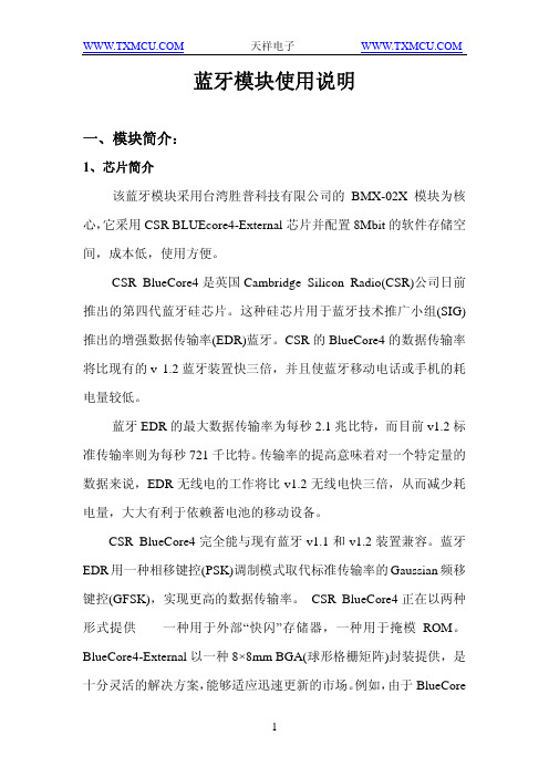
蓝牙模块使用说明一、模块简介:1、芯片简介该蓝牙模块采用台湾胜普科技有限公司的BMX-02X模块为核心,它采用CSR BLUEcore4-External芯片并配置8Mbit的软件存储空间,成本低,使用方便。
CSR BlueCore4是英国Cambridge Silicon Radio(CSR)公司日前推出的第四代蓝牙硅芯片。
这种硅芯片用于蓝牙技术推广小组(SIG)推出的增强数据传输率(EDR)蓝牙。
CSR的BlueCore4的数据传输率将比现有的v 1.2蓝牙装置快三倍,并且使蓝牙移动电话或手机的耗电量较低。
蓝牙EDR的最大数据传输率为每秒2.1兆比特,而目前v1.2标准传输率则为每秒721千比特。
传输率的提高意味着对一个特定量的数据来说,EDR无线电的工作将比v1.2无线电快三倍,从而减少耗电量,大大有利于依赖蓄电池的移动设备。
CSR BlueCore4完全能与现有蓝牙v1.1和v1.2装置兼容。
蓝牙EDR用一种相移键控(PSK)调制模式取代标准传输率的Gaussian频移键控(GFSK),实现更高的数据传输率。
CSR BlueCore4正在以两种形式提供——一种用于外部“快闪”存储器,一种用于掩模ROM。
BlueCore4-External以一种8×8mm BGA(球形格栅矩阵)封装提供,是十分灵活的解决方案,能够适应迅速更新的市场。
例如,由于BlueCore是目前可以得到的唯一能够支持蓝牙v1.2规格的所有强制和可选功能的硅芯片,BlueCore4-External为PC应用程序提供了理想的解决方案,使它们得益于以三倍速度的传输率无线传输文件,或者同时操作多个高需求的蓝牙链路。
鉴于蓝牙固件安装在芯片只读存储器上,CSR BlueCore4-ROM 的成本较低,占用面积小得多(在小片尺寸包装中为3.8×4mm,在与BC2-ROM和BC3-ROM引脚兼容的BGA中为6×6mm)。
SW20蓝牙模块使用说明书
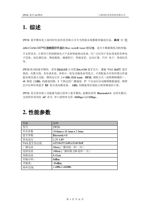
1. 综述SW20蓝牙模块是上海同时信息科技有限公司专为智能无线数据传输而打造,具有32 位ARM Cortex M0™处理器国际标准的Blue-tooth® Smart协议栈,适合小数据极低功耗传输,不支持语音,主要用于控制桥接电子产品和智能移动设备,可广泛应用于有此需求的各种电子设备,如仪器仪表,物流跟踪,健康医疗,智能家居,运动计量,汽车电子,休闲玩具等。
SW20低功耗蓝牙模块,采用DIALOG公司的DA14580蓝牙芯片,遵循V4.0 GATT 蓝牙规范,内置天线。
具有成本低、体积小、收发灵敏度高等优点,只需配备少许的外围元件就能实现其强大功能。
模块运行在2.4 GHz ISM band,GFSK 调制方式(高斯频移键控),40 频道2 MHz 的通道间隙,3 个固定的广播通道,37 个自适应自动跳频数据通道,物理层可以和经典蓝牙RF 组合成双模设备,MHz 间隙能更好地防止相邻频道的干扰。
SW20 是目前市面上功能最为强大的串口蓝牙模块,起模块采用Bluetooth4.0、支持从模式、支持简单易用的AT 命令, 串口波特率支持4800bps~115200bps。
2.性能参数性能说明型号SW20外形参数16.6mm x 10.5mm x 2.3mm蓝牙参数Bluetooth 4.0供电电压 2.2V-3.6VV4.0蓝牙协议栈ATT,GATT,SMP,L2CAP,GAP广播电流30uA (广播间隔一秒/一次)连接电流100uA (广播间隔250毫秒/一次)休眠电流0.45uA传输功率:0dBm灵敏度:-93dBm频率范围: 2.4GHz-2.480GHz功能框图3. 管脚描述NCWAKE_MCU WAKE_SW20SDA/GPIO0SCL/GPIO1RXDTXD GND NC NC STATUS VCC GNDGND管脚号管脚名称管脚描述1 NC 预留管脚,悬空2 WAKE_MCU模块唤醒MCU接收数据控制脚(模块发送数据时自动拉低,方便唤醒,数据发送完后自动拉高)3 WAKE_SW20 MCU唤醒模块发送数据控制脚(MCU发送数据时自动拉低,方便唤醒,数据发送完后自动拉高)4 SDA/GPIO0 I2C接口或GPIO05 SDA/GPIO1 I2C接口或GPIO16 TXD 模块给外部MCU发送串口数据7 RXD 外部MCU给模块发送串口数据8 GND 地9 VCC 电源脚Vmin=2.35V,Vmax=3.3V10 STATUS 蓝牙状态管脚(是否处于连接状态,处于连接状态为低,处于断开状态位高)11 NC 预留管脚,悬空12 NC 预留管脚,悬空13 GND 地14 GND 地4.典型应用本模块为透传模块,低功耗蓝牙模块透传协议,手机APP通过本协议可以让蓝牙模块工作在透传模式(串口透传)和命令模式。
维赛斯Vitesse 4ATMOD 无线控制器说明书

OverviewThe VITM4-ATMOD is a wireless controller with a relay output capable of switching incandescent, fluorescent and compact fluorescent lighting when connected to Vitesse Modular Switching Modules (refer to the user guide for the VITM4-S and VITM4-E for installation and wiring).The output comprises a mains voltage relay capable of simple on/off switching.The unit also includes stored scenes for versatile manual control of lighting levels.This device is integrated with other devices as part of an An -10® lighting control system. The built -in RF transceiver allows wireless communication with all other An -10® compatible products, e.g. the AT -BB -INInput Unit, useful for push -button scene selection and absence detection.All functionality is fully programmable.FeaturesIR ReceiverReceives control and programming commands from an IR (infrared) handset (Fig.2).Status LEDsThese flash R ed and/or G reen to indicate the following:Vitesse Modular Connector Connector function. • Power Input & Switched Output (Channel 1)Used to connect mains power to the unit and to connect a switched load.Fig 2: Front features (VITM4-ATMOD shown)Valid setting receivedInvalid setting receivedSoftware reset received Factory reset receivedRF VITM4 switching moduleClear casingwhich covers.....IR Receiver Status LEDsVitesse ModularConnectorVITM4-ATMODFig 1Push VITM4-ATMOD into either the end of a VITM4-S or a VITM4-E as shown in Fig 4 below.Fig 3: Vitesse Modular + An -10 componentVITM4-SVitesse modular starter for dimming systemsVITM4-EVitesse modular extender for dimming systemsVITM4-ATMODWhat if the load does not turn ON?• Check that the live supply to the Vitesse Modular VITM4-S.• Check that the load is functioning by bypassing the Controller (e.g. link terminals L and SW/L on the VitesseModular VITM4-S).• Check that the unit is correctly addressed, see ‘Step 1: Set channel addresses and channel load type ’ on page 3.Fault findingFig 4: VITM4-ATMOD installationStep 1: Set channel addresses and channel load typeThe functionality of the VITM4-ATMOD is controlled by a number of parameters which can be changed or programmed by any of the following devices:• UHS4 Infrared Handset• UNLCDHS Infrared Handset (with LCD)For most basic programming operations the UHS4 handset is recommended and the following procedures are based on using this device.Point the handset at the Controller and send the required programming commands to the unit as shown in Steps 1, 2 and 3.Valid commands will be indicated by a green LED flash. See page 1 for details of other LED responses.The Controller has one switched output channel.To relate the function of different channels it is necessary to set the addresses correctly. For example, a sceneselect message sent from a device with a Local Code of 1 will only be actioned by devices that also have a Local Code of 1.The output channel also has a Circuit number. This allows different physical channels to be linked and controlled as a single Circuit.Step 3: Re -program scenesThe VITM4-ATMOD has capacity to store 20 Local Scenes and 120 Area Scenes. By default all Scenes are pre -programmed with the following channel levels, but these can be changed as required: NOTE: Local Scene 20 and Area Scene 120 are designated ‘off ’ scenes within a system and shouldnormally be programmed with all channels off or at zero.Scenes can be recalled by using an IR Handset or by a switch/button plate via an AT -BB -IN Input Unit.Local Scenes 12 3 4 5 6 ... 19 20 Ch1 onononononon...onoffArea Scenes101 102 103 104 105 106 ...119 220 Ch1 onononononon...onoffThe tables on pages 12 to 15 give a summary of all programmable parameters for the VITM4-ATMOD Controller.This page intentionally left blankDue to our policy of continual product improvement CP Electronics reserves the right to alter the specification of this product without prior notice.Dimensions See diagrams opposite Weight0.1kgSupply Voltage 230VAC +/- 10% Frequency50HzMaximum LoadChannel 1 (switching):10A of lighting and/or ventilationincluding incandescent, fluorescent, compact fluorescent, low voltage (by switching the primary of transformer).Terminal Capacity Refer to the user guide for the VITM4-S and VITM4-E for installation and wiring. Receiver Class2/complianceTransmitter Duty Cycle <10% on g3 band (default band)<0.1% on g2 band <1% on g1 bandRange The maximum RF range between An -10devices is 100m in free air and up to 30mindoors. However the materials used within a building will vary and this will impact upon the RF range. In reality the nature of how the An -10’s hybrid -mesh works means that in most scenarios the individual range of an An -10 product will not be important.Temperature 0ºC to 35ºCHumidity5 to 95% non -condensingMaterial (casing) Flame retardant polycarbonateEBDSPIR -AT -PRM RF Ceiling PIR presence detector – switchedEBDSPIR -AT -AD RF Ceiling PIR presence detector – 1-10V dimming EBDSPIR -AT -DD RF Ceiling PIR presence detector – DALI/DSI dimming AT -BB -IN RF Input unitAT -SL -R RF relay controllerAT -SL -R -SA RF relay controller (standalone) AT -SL -ADR RF 1-10V + relay controllerAT -SL -ADR -SA RF 1-10V + relay controller (standalone) AT -SL -DDR RF DALI/DSI + relay controllerAT -SL -DDR -SA RF DALI/DSI + relay controller (standalone) VITM6-ATMOD -AD RF VITM6 1-10V module VITM6-ATMOD -DD RF VITM6 DALI/DSI module UHS4 Programming IR handset UNLCDHSUniversal LCD IR handsetC.P. Electronics Ltd Brent Crescent London NW10 7XRUnited Kingdom Tel: + 44 (0) 333 900 0671 Fax: + 44 (0) 333 900 0674 ************************.ukRef: #WD388 Issue 4Part numbers。
- 1、下载文档前请自行甄别文档内容的完整性,平台不提供额外的编辑、内容补充、找答案等附加服务。
- 2、"仅部分预览"的文档,不可在线预览部分如存在完整性等问题,可反馈申请退款(可完整预览的文档不适用该条件!)。
- 3、如文档侵犯您的权益,请联系客服反馈,我们会尽快为您处理(人工客服工作时间:9:00-18:30)。
维亚思控制器蓝牙模块使用说明书
(原创版)
目录
1.维亚思控制器蓝牙模块概述
2.蓝牙模块的功能特点
3.蓝牙模块的安装与连接
4.蓝牙模块的使用方法
5.蓝牙模块的注意事项
6.蓝牙模块的故障排除与维护
正文
一、维亚思控制器蓝牙模块概述
维亚思控制器蓝牙模块是一款功能强大、易于使用的蓝牙设备,适用于各种需要无线连接的场景。
该模块采用了先进的蓝牙技术,具有较高的稳定性、可靠性和兼容性,可与市面上大部分蓝牙设备连接。
二、蓝牙模块的功能特点
1.高稳定性:维亚思控制器蓝牙模块采用了高性能的蓝牙芯片,确保了在各种环境下都能保持稳定连接。
2.高兼容性:模块支持蓝牙 4.0 及以上版本,可与市面上大部分蓝牙设备无缝连接。
3.低功耗:模块具有低功耗特性,即使长时间使用也不会对设备的续航造成明显影响。
4.多功能:模块支持数据传输、音频传输等多种功能,满足不同场景的需求。
三、蓝牙模块的安装与连接
1.安装:蓝牙模块采用标准接口设计,可轻松插入设备的相应接口进行安装。
2.连接:安装完成后,打开设备的蓝牙设置,搜索附近的蓝牙设备,找到模块的设备名称并点击连接,即可完成配对。
四、蓝牙模块的使用方法
1.数据传输:连接成功后,可通过蓝牙模块在设备间传输数据,如文件、图片等。
2.音频传输:模块支持音频传输功能,可连接蓝牙耳机、音响等设备播放音乐、接听电话等。
五、蓝牙模块的注意事项
1.请勿将蓝牙模块置于潮湿、高温的环境中,以免损坏设备。
2.在使用过程中,请勿让模块受到强烈撞击或摔落,以免影响使用寿命。
3.如有异常现象,请立即断开电源并联系售后服务。
六、蓝牙模块的故障排除与维护
1.若连接过程中出现配对失败,请尝试重新开启蓝牙设备或重新安装模块。
2.若传输数据时出现中断或速度慢,请检查蓝牙设备之间的距离是否过远,或尝试更换传输方式。