冲击回波测试仪使用说明书
CTG操作说明书
CTG-1TF混凝土厚度测试仪操作说明书CTG的特点:它能够对接收到的信号频谱用图形显示出来(能够在仪器上存储并回放),这样可以将直观地显示出测得的数据质量,分辨出不合格的数据。
这套仪器也可用于确定测试圆柱及其它已知厚度式样的相对混凝土质量(通过测试混凝土压缩波波速)。
这与测试材料的性质及其内部结构有关。
CTG系列包括两个测试范:THIN范围使用内置的螺线管作为冲击源,可以测试8~55cm范围的厚度。
THICK范围用于测试55cm以上厚度,而且需要使用外置锤(以产生更大的低频能量)来激发冲击来进行回波频率测试。
设置测试范围是通过在启动仪器时,输入设计厚度值自动完成的,或者在操作过程中通过主菜单手工设定。
基本操作1、当连接好测试探头后,就可以按“push-on/push-off(仪器开关)”来启动CTG了。
这时,屏幕上就会显示CTG的型号以及软件的版本号,接着显示仪器内存中已经存储的记录数目。
然后,程序要求用户输入板或墙的设计厚度(单位为:inch 或cm)。
这时,用键盘输入测试区域的预期厚度或设计厚度。
CTG-1就会用这个设计厚度设定测试范围(THIN或THICK)、最大厚度(比设计厚度大33%),并且在三个峰值选定运算法则中选择一个适用于相应厚度范围的运算法则。
例如,如果输入了一个期望厚度为9inch,那么最大厚度将会是11inch,将会选定THIN模式,并且将会使用“中等”厚度选定最优化路线来进行自动数据分析。
如果不知道期望厚度,只需要输入一个较大的值,使CTG能够在一个更广的厚度范围内搜索。
对于使用螺线管(THIN模式)冲击器的未知厚度的较薄构件如板或墙,可以输入一个19~24inch范围内的值。
如果要在THICK模式下测试较厚的构件,如不知其大概厚度,可以输入一个90~110inch范围内的值。
以后,如果有必要的话,用户可以根据采集到的整个波形显示来缩窄实际厚度范围,再次进行测试。
2.输入设计厚度后,计算出的最大厚度值就立即显示出来了。
XJF冲击试验机说明书 -表盘(万塑)

注意事项1、保存说明书以备参考。
在使用本仪器之前,务必仔细阅读本说明书。
2. 请勿在近水的地方使用该仪器。
3. 请勿在不平稳的地方放置该仪器。
4. 在指定电源条件下使用该仪器。
5. 为确保安全,该仪器配有三线接地插座,这个插座只适用于接地型电源接口。
如果这个插座不能与接口连接,请向电气工程师咨询,选取合适的插座。
6. 不要在电源线上放置任何物品,不要将该仪器放到人们可以踏到电源线的地方。
7. 如果本仪器使用延长线,确保延长线与原电线的额定电流一致。
8. 不要移动该仪器的任何面板,如不遵守此操作规程将导致火灾或电击的危险。
不要在机体上喷洒任何液体。
9. 为防止触电,请不要自己维修本仪器。
打开或移走机壳,可能会有高压危险。
10. 如果有下述情况,请不要给仪器供电,请向服务部门咨询。
1)当电源线和插座损坏或磨损时;2)当有液体洒到机器上时;3)该仪器淋雨或沾水时。
11. 本仪器及其附件必须置于干燥的环境内。
12. 在试验完成之后,必须关掉电源,以免发生意外情况。
13.在试验时,操作者务必注意安全。
不做试验时,请不要把摆锤放在放摆机构上。
14.当摆动轴承长期未清洗摆动不灵活时,造成能量损失超差,这样应用120#以上的汽油清洗摆轴轴承,清洗后注入适量5# 或7# 高速机油或钟表油均可。
15.当冲击试样长期磨损引起刀刃钳口变形时,应更换其磨损件。
21 概述1.1仪器标准:XJF 摆锤冲击试验机主要用于硬质热塑性塑料和热固性塑料,填充和纤维增强塑料,增强尼龙、玻璃钢、陶瓷、铸石、电绝缘材料以及这些塑料的板材,包括层压板材。
是化工行业、科研单位、大专院校、塑料产品生产厂家、质量研究和检测等部门理想的试验设备。
本仪器符合GB/T1843《塑料悬臂梁冲击试验方法》和ISO180,ASTM256,GB/T2611,GB/T21189 IS0179、GB/T1043标准的要求。
是一种结构简单、操作方便、数据准确可靠的冲击试验机。
冲击试验仪操作规程

冲击试验仪操作规程1. 目的本操作规程旨在确保冲击试验仪的正常运行,保障操作人员的安全,并准确获取试验数据。
2. 适用范围本操作规程适用于所有使用冲击试验仪进行试验的操作人员。
3. 设备准备3.1 确保冲击试验仪正常工作,仪器无故障,并按照规定时间进行维护和保养。
3.2 确认所需试验样品及相关试验设备已准备就绪。
4. 试验操作步骤4.1 操作人员应仔细阅读试验样品的相关说明,了解试验要求和试验方法。
4.2 打开冲击试验仪的电源,确保电源连接正常。
4.3 将试验样品放置在试验台上,并根据试验要求进行固定。
4.4 设置试验参数,包括冲击能量、冲击角度等。
4.5 按下开始按钮,开始试验。
4.6 在试验过程中,操作人员应密切关注试验仪的运行情况,并记录试验数据。
4.7 完成试验后,关闭冲击试验仪的电源。
5. 安全注意事项5.1 操作人员应佩戴个人防护装备,包括护目镜、手套等。
5.2 在操作过程中,严禁触摸冲击试验仪的运动部件。
5.3 禁止将手指或其他物体放入试验台内。
5.4 在试验过程中,如发生异常情况或故障,应立即停止试验,并通知维修人员处理。
5.5 禁止在试验台周围堆放杂物,以免影响试验操作和试验结果。
6. 维护和保养6.1 定期对冲击试验仪进行维护和保养,确保其正常运行。
6.2 清洁试验台和设备表面,保持整洁。
6.3 定期校准试验参数,确保试验数据的准确性。
7. 附则7.1 未在本操作规程中涉及的问题,应根据相关法规和规定执行。
7.2 本操作规程的解释权归工作人员所有。
以上是冲击试验仪操作的规程,操作人员应遵守本规程,并确保试验操作的安全和准确。
如有任何疑问,请咨询相关负责人或有关部门。
福禄克 冲击力量测试仪操作说明书
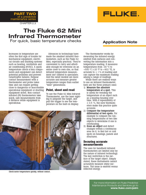
The Fluke 62 Mini Infrared ThermometerFor quick, basic temperature checksAdvances in technology have made the smallest infrared ther-mometers, such as the Fluke 62 Mini, especially practical. They’re convenient to carry and afford-able enough for everyone on an entire crew to own one, so that infrared temperature measure-ment isn’t limited to specialists. And the latest models are more accurate and measure greater temperature ranges than earlier “mini” generations.Point, shoot and readTo use the Fluke 62 Mini Infrared Thermometer, use the laser sight-ing to pinpoint the target, and pull the trigger to see the tem-perature on the built-in display.Increases in temperature are often the first sign of trouble for mechanical equipment, electri-cal circuits and building systems such as heating, ventilation and air conditioning (HVAC). A quick temperature check of key compo-nents and equipment can detect potential problems and prevent catastrophic failures. Regular contact measurement with a thermometer and probe takes time and can require gettingclose to dangerous or inaccessible operational equipment or shutting equipment down. Non-contact infrared (IR) thermometers take quick, safe measurements from a distance while equipment is operational.Application NoteFor more information on Fluke Predictive PART TWOof a predictive maintenance seriesCheck motor temperatures quickly, without contact.The thermometer works by measuring the infrared energy emitted from surfaces and con-verting the information into a temperature reading. It measures temperatures from -30 °C to +500 °C (-20 °F to +932 °F), is accurate to ± 1% of reading and can capture the maximum reading among a range of readings.While there are endless ways to use an infrared thermometer, here are the three primary ones:1) M easure the absolutetemperature at a spot. This is useful for trending thetemperature of an object such as a bearing housing over time. With a repeatability of ± 0.5 %, the new thermom-eters make this practice quite accurate.2) C ompare the temperature differential of two spots. For example to compare the run-ning temperatures of two like objects to determine if one is overheating.3) S can an object and detect changes within a continuous area on it, to find hot or cold spots on housings, panels and structures.Securing accurate measurementsThe uses for handheld infrared thermometers are limited only by the nature of infrared technology. The key restriction is the sur-face of the target object. Simply stated, these instruments cannot accurately measure shiny sur-faces. The issue is emitted versusreflected energy.CHAPTER 2.3EmissivityOf the kinds of energy—reflected, transmitted and emitted—emanat-ing from an object, only emitted infrared energy indicates the object’s surface temperature. Transmitted and reflected energy do not. When IR thermometers measure surface temperatures, they sense all three kinds of en-ergy. Therefore, they have to be adjusted to read emitted energy only. The Fluke 62 Mini Infrared Thermometer has a fixed, pre-set emissivity of 0.95, which is the emissivity value for most organic materials as well as painted or oxidized surfaces.To accurately measure the surface temperature of a shinyobject, cover the target surfacewith masking tape or flat blackpaint and allow enough timefor the tape or paint to reachthe temperature of the material underneath.Distance-to-spot ratioThe optical system of an infrared thermometer collects the infrared energy from a circular area or spot and focuses it on the detec-tor. The farther a target is fromcreated on the target will be. Optical resolution is defined by the ratio of the distance from theglass and, as noted, will be inac-curate if used to measure shiny or polished metal surfaces (stainless steel, aluminum, etc.).Users of IR thermometers also must be alert to environmen-tal conditions. Steam, dust and smoke, for example, can prevent accurate temperature readings by obstructing a unit’s optics. A dirty lens can also affect read-ings. Lenses should be cleaned with dry, clean plant air or a fluid made specifically for cleaning lenses. Also, changes in ambi-ent temperature can influence a thermometer’s performance. If an IR unit is exposed to abrupt temperature changes of 11 °C (20 °F) or more, the user should allow at least 20 minutes for the unit to adjust to the new ambienttemperature.instrument to the object com-pared to the size of the spot (“dis-tance-to-spot” or D:S ratio). For the Fluke 62 Mini the distance-to-spot ratio is 10:1. This means that at a distance of 10 inches the spot is about one inch in diam-eter. The larger its ratio number the better is the instrument’s resolution. Resolution is important becauseit relates directly to getting good readings by ensuring that the target is larger than the spot size. The smaller the target, the closer one must be to it. When accuracy is critical, the target should be at least twice as large as the spot. Other factors to consider These instruments measure only surface temperatures, not internal temperatures. Furthermore, they cannot take readings throughEven considering the limitations of infrared temperature moni-toring, there are still so many possible uses for this technology that trying to list them all would be fruitless. Here are some of the most common and particularly successful applications. Predictive maintenance Regular maintenance in industrial and institutional locations keeps motors, pumps and gearboxes from experiencing catastrophic failures that can halt production or pose safety problems. In an infrared maintenance program, technicians set up an inspection route and measurement param-eters for each piece of key equip-ment and/or component. Then, they take an infrared temperature measurement on a regular basis, record the measurement, and compare against previous read-ings for any changes.As an example, a technician can use a Fluke 62 Mini to check the operation of an induction motor on a critical piece of equip-ment. She or he would start by reading the unit’s specifications on the plate attached to it. The plate will reveal either a Temper-ature Rise Rating or a Motor Class Rating for the motor. The rise rat-ing gives the maximum allowable operating temperature above am-bient. The motor class rating, e.g. “Class A,” will reveal an absolute maximum operating temperature. Both pertain to internal-winding temperatures. Of course, a contact thermometer cannot measure these temperatures while the motor is running. However, an operator or technician can use a non-contact IR thermometer to measure the temperature of the motor case. She or he should add 10 °C (18 °F) to surface scans to determine the internal operating temperature. For each 10 °C (18 °F) above the maximum operating temperature, the life of the motor is likely to decrease by 50%.If the motor is extremely hot it could be a fire hazard.Using infrared thermometryfor plant maintenance reducesrepair costs and avoids equip-ment stoppages. Industrialmaintenance personnel, buildingmanagers, HVAC technicians andeven homeowners can reducecosts by repairing only whatneeds to be fixed. They can avoidunplanned equipment stoppagesby making specific, necessaryrepairs before equipment fails.Then, after repairs, they can per-form new temperature measure-ments on the same equipment todetermine whether the repairswere successful.Electrical inspectionsElectrical systems supply essen-tial power to every industrial,commercial and residential set-ting. With degradation over timeand the general vulnerability ofelectrical connections, it’s impor-tant to monitor electrical sys-tems for loose, dirty or corrodedconnections, flaws in transformerwindings, hot spots in panelboxes and other telltale signs oftrouble.The Fluke 62 Mini can beinvaluable for finding developinghotspots in electrical equipmentthat may indicate a short circuit,a fused switch or an overload. Ingeneral, higher operating temper-atures reduce the life of electricalcomponents by damaging insula-tion and raising the resistance ofconductor materials. Pinpointedby a non-contact IR thermometer,these situations signal that actionis required.Measure moving targets easily.Use unit in close range fornear-distance targets.HVAC inspectionsHeating and cooling systems, whether for maintaining pro-duction parameters or human comfort, are easily monitored with the Fluke 62 Mini Infrared Thermometer. Check air stratifica-tion, supply and return registers, furnace performance and steam distribution systems and conduct energy audits to pinpoint system upgrade opportunities.For example, IR non-contact thermometers can be used to troubleshoot steam traps, which are designed to remove water (condensate) that has condensed from the steam as it travels in transfer pipes. If a steam trap fails while open, it will leak steam, causing an energy loss. If it fails while closed, it won’t remove condensate from the steam line, making it useless. A faulty steam trap can cost a plant $500 USD or more per year, and in any given year, 10 % of all industrial steam traps fail. Since many plants have as many as 1,000 traps, they can quickly become high-value main-tenance targets.To verify whether a steam trap is working properly, use a non-contact thermometer like the 62 Mini to measure from input to output. On a properly operating trap, the temperature should drop significantly. If the temperature doesn’t drop, the steam trap has failed open and is passing super-heated steam into the condensate line. If the temperature drop is overly large, the trap may be stuck closed and is not ejecting heated condensate. Condensate in steam lines reduces the effec-tive energy of the steam and can cause difficulties in steam drivenprocesses.Use non-contact temperature measurements for inaccessible targets.Fluke.Keeping your worldup and running.Fluke CorporationPO Box 9090Everett, WA USA 98206Fluke Europe B.V.PO Box 1186, 5602 BDEindhoven, The NetherlandsFor more information call:U.S.A. (800) 443-5853 orFax (425) 446-5116Europe/M-East/Africa (31 40) 2 675 200 orFax (31 40) 2 675 222Canada (800) 36-FLUKE orFax (905) 890-6866Other countries (425) 446-5500 orFax (425) 446-5116Web access: ©2005 Fluke Corporation. All rights reserved.Printed in U.S.A. 6/2005 2517382 A-EN-N Rev A。
冲击测试器操作指引
项目:
文件编号:RGQC-WI-016
冲击测试器操作指引
版本/版次:A/0
生效日期:2017年2月25日
页数:第1页,共1页
编写:批核:
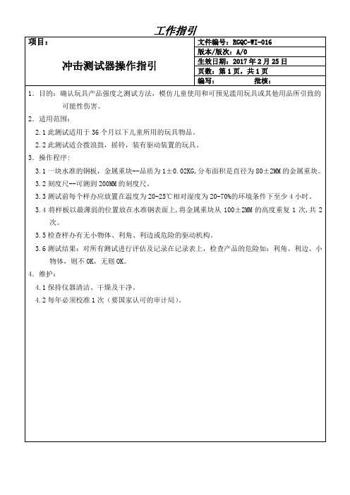
1.目的:确认玩具产品强度之测试方法,模仿儿童使用和可预见滥用玩具或其他用品所引致的
可能性伤害。
2.适用范围:
2.1此测试适用于36个月以下儿童所用的玩具物品。
2.2此测试适合拨浪鼓,摇铃,装有驱动装置的玩具。
3.操作程序:
3.1一块水准的钢板,金属重块ห้องสมุดไป่ตู้-品质为1±0.02KG,分布面积是直径为80±2MM的金属重块。
3.2刻度尺--可测到200MM的刻度尺。
3.3测试前每个样办应放置在温度为20-25℃相对湿度为20-70%的环境条件下至少4小时。
3.4将样板以最薄弱的位置放在水准钢表面上,将金属重块从100±2MM的高度重复1次,共2次。
3.5检查样办有无小物体、利角、利边或危险的驱动机构。
3.6测试结果:对所有测试进行评估及记录在记录表上,检查产品的危险如:利角、利边、小物体,则不OK,无则OK。
4.维护:
4.1保持仪器清洁、干燥及干净。
4.2每年必须校准1次(要国家认可的审计局)。
冲击回波测试仪使用说明书

湖南芯仪电子科技有限公司
目录
1. 适用范围.........................................................................................................................1 2. 测试原理.........................................................................................................................1
2.1 冲击回波技术....................................................................................................... 1 2.2 仪器测试原理....................................................................................................... 2 2.3 超声透射缺陷测试技术...................................................................................... 2 3. 性能介绍.........................................................................................................................4 3.1 性能特点................................................................................................................4 3.2 技术参数................................................................................................................4 4. 测试主机.........................................................................................................................5 4.1 仪器外形................................................................................................................5 4.2 硬件与按键功能...................................................................................................5 4.3 显示界面................................................................................................................6 5. 操作说明.......................................................................................................................15 5.1 仪器连接............................................................................................................. 15 5.2 单面缺陷测量.....................................................................................................16
冲击回波法检测教学讲义

接收器
接收器
用于接收并响应被测结构中的应力波,将信号转换为可测量 的电信号。
接收器类型
常用的接收器有压电式、磁电式和电动式等,根据检测需求 选择合适的接收器。
数据采集系统
数据采集系统
用于采集、记录和显示接收器输出的电信号,以便进行分析和处理。
数据采集系统组成
包括信号放大器、滤波器、模数转换器和计算机等,确保数据采集的准确性和稳 定性。
在冲击回波法中,使用超声探头 接收反射回来的回波信号。回波 信号的强度和波形反映了界面的 性质和状态。
回波的处理
接收到的回波信号需要进行处理 ,包括信号放大、滤波、数字化 等步骤,以便后续的分析和处理 。
信号的分析与解释
信号的分析
对处理后的回波信号进行分析,提取 有关界面性质和状态的信息,如反射 系数、折射系数、声速等。
。
数据处理
根据实验目的对数据进行处理 ,如滤波、去噪等,以提高数
据质量。
结果分析
根据处理后的数据,分析材料 性能,如弹性模量、阻尼比等
,并得出结论。
结果评估与报告
对实验结果进行评估,撰写详 细的实验报告,包括实验目的
、方法、结果和结论等。
05
冲击回波法的实验结果与解释
实验结果展示
实验数据记录
详细记录每次实验的输入参数、实验步骤、实验环 境和实验数据,确保数据的完整性和准确性。
信号发生与采集
调整参数
通过信号发生器产生冲击信 号,并使用采集设备记录材
料对冲击信号的响应。
根据实验需求,调整信号发 生器和采集设备的参数,以
获取最佳的测试效果。
重复实验
为了确保数据的准确性 和可靠性,需要进行多
冲击试验机操作规程
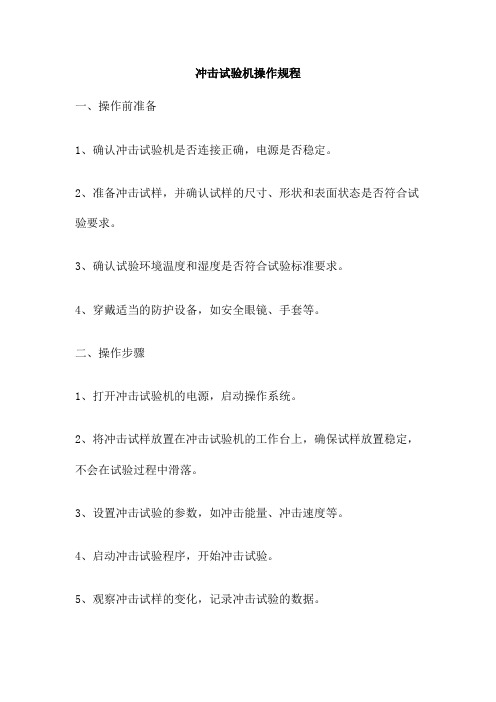
冲击试验机操作规程一、操作前准备1、确认冲击试验机是否连接正确,电源是否稳定。
2、准备冲击试样,并确认试样的尺寸、形状和表面状态是否符合试验要求。
3、确认试验环境温度和湿度是否符合试验标准要求。
4、穿戴适当的防护设备,如安全眼镜、手套等。
二、操作步骤1、打开冲击试验机的电源,启动操作系统。
2、将冲击试样放置在冲击试验机的工作台上,确保试样放置稳定,不会在试验过程中滑落。
3、设置冲击试验的参数,如冲击能量、冲击速度等。
4、启动冲击试验程序,开始冲击试验。
5、观察冲击试样的变化,记录冲击试验的数据。
6、在冲击试验结束后,关闭冲击试验机,并整理试验数据。
三、操作注意事项1、在操作冲击试验机时,必须遵守安全操作规程,确保人身安全和设备安全。
2、冲击试验机的使用必须符合国家相关法律法规的规定。
3、在进行冲击试验前,必须对冲击试验机进行充分的检查和维护,确保设备处于良好状态。
4、在冲击试验过程中,如发现异常情况,应立即停止试验,并报告相关人员进行处理。
5、在完成冲击试验后,应对冲击试验机进行清理和维护,确保设备长时间使用保持良好的状态。
四、操作后处理1、对冲击试验的数据进行整理和分析,得出试验结果。
2、根据试验结果,对冲击试样进行评价或提出改进建议。
3、清理冲击试验机的工作台和设备周围的杂物和垃圾。
硫化机操作规程一、操作前准备1、确认硫化机是否处于安全状态,包括紧固件是否松动,安全阀、压力表、电气线路是否正常。
2、检查液压油、润滑油的油位是否正常,如有需要,及时添加。
3、打开硫化机电源,检查各部分指示灯是否正常。
4、根据待硫化的物料特性,设置硫化时间和硫化温度。
二、操作步骤1、将待硫化的物料放置在硫化机内,关闭模具,并确保其紧固。
2、打开加热系统,将硫化温度升至设定值。
3、开启液压系统,对模具进行加压,直至达到设定压力。
4、保持压力不变,继续加热一定时间,然后关闭加热系统和液压系统,完成硫化。
5等待一段时间,待模具冷却后,打开模具取出硫化好的物料。
- 1、下载文档前请自行甄别文档内容的完整性,平台不提供额外的编辑、内容补充、找答案等附加服务。
- 2、"仅部分预览"的文档,不可在线预览部分如存在完整性等问题,可反馈申请退款(可完整预览的文档不适用该条件!)。
- 3、如文档侵犯您的权益,请联系客服反馈,我们会尽快为您处理(人工客服工作时间:9:00-18:30)。
(a)
(b)
f
图 2.2 底边反射与缺陷边界反射:(a) 已知厚度混凝土块;(b) 频谱图
2.3 超声透射缺陷测试技术
第2页
冲击回波测试仪使用说明书
声波是弹性波的一种,若视混凝土介质为弹性体,则声波在混凝土中的传播 服从弹性波传播规律,由发射探头发射的声波经构件到达接收探头。 探头发射 的声波会在发射点和接收点之间形成复杂的声场,声波将分别沿不同的路径传 播,最终到达接收点,其走时都不尽相同。但在所有的传播路径中总有一条路径, 声波走时最短,接收探头接收到该声波时,形成信号波形的初始起跳,一般称为 “初至”,当桩身完好时,可认为这条路径就是发射探头和接收探头的直线距离, 是已知量;而初至对应的声时扣去声波在测管、水之间的传播时间以及仪器系统 延迟时间,可得声波在两测管间混凝土介质中传播的实际声时,并由此可计算出 所对应的声速。
冲击回波测试仪使用说明书
SET-PI2-01 型冲击回波测试仪ቤተ መጻሕፍቲ ባይዱ明书
SET-PI2-01 型冲击回波测试仪是一款以冲击回波检测技术为基础的钢筋混 凝土结构内部缺陷检测专用的便携式测试仪器。仪器采用 7 寸高亮度真彩液晶触 摸显示屏,独立、交互式按键/触摸操作,操作方便;单/双通道数据采集,能够 同时进行测试,测试效率高,双通道波速测试方便快捷;数据存储使用 SD 卡, 存储容量大,数据保存、读取方便;仪器配置专用信号激发装置,使用方便,敲 击信号稳定度高,重复性好;专业化的数据后处理软件可实现色谱成像,缺陷识 别精度高。
5.2.1 参数设置...................................................................................................16 5.2.2 文件名、测点位置设置..........................................................................17 5.2.3 测量........................................................................................................... 17 5.3 波速标定............................................................................................................. 18 5.4 时差超声测量.....................................................................................................18 5.5 超声透射缺陷测试.............................................................................................19 5.5.1 参数设置...................................................................................................19 5.2.2 文件名、测点位置及测距设置.............................................................19 5.2.3 测量........................................................................................................... 20 6. 维护与维修...................................................................................................................20 6.1 电池充电............................................................................................................. 20 6.2 仪器保养............................................................................................................. 21 6.3 仪器维修............................................................................................................. 21
2.1 冲击回波技术....................................................................................................... 1 2.2 仪器测试原理....................................................................................................... 2 2.3 超声透射缺陷测试技术...................................................................................... 2 3. 性能介绍.........................................................................................................................4 3.1 性能特点................................................................................................................4 3.2 技术参数................................................................................................................4 4. 测试主机.........................................................................................................................5 4.1 仪器外形................................................................................................................5 4.2 硬件与按键功能...................................................................................................5 4.3 显示界面................................................................................................................6 5. 操作说明.......................................................................................................................15 5.1 仪器连接............................................................................................................. 15 5.2 单面缺陷测量.....................................................................................................16
第1页
冲击回波测试仪使用说明书
2.2 仪器测试原理
图 2.1 冲击回波测试技术原理
机械波在介质中传播并在某个界面反射,界面与机械波传播起点距离为 S, 则波速 Vp 与频率 f 满足如下关系式:
S Vp
(1)
2f
在上式(1)中三个未知量中,对于同一钢筋混凝土结构构件波速 Vp 为不变的常量。
利用 SET-PI2-01 冲击回波测试仪我们可以首先应用反射波法或透射波法测 试出构件波速。对于未知的缺陷位置,仅需要已知(1)式中的频率 f 即可计算、确 定缺陷位置。SET-PI2-01 冲击回波检测仪将测试过程中的机械应力波进行实时记 录,将这些测试信号导入相关测试软件,软件对其进行傅里叶频谱变换,谱图中 的主频为冲击表面、缺陷界面及其它界面之间的多次反射产生瞬态共振所致,通 过对主频的提取即可以确定结构中缺陷位置。图 2.2 为缺陷边界与底边反射频谱 示意图。
1. 适用范围
(1) 钢筋混凝土桥梁综合检测(混凝土抗压强度、厚度、裂缝深度、空洞、密实度、 结合面质量、表面损伤层厚度);
(2) 桥梁预应力管道注浆密实度; (3) 混凝土路面、沥青层公路边坡厚度与结合面质量; (4) 隧道衬砌厚度与结合面质量; (5) 飞机跑道厚度与内部缺陷。
2. 测试原理
2.1 冲击回波技术 冲击回波法是一种基于应力波传播特性的无损检测法,其原理是利用机械方
当构件内存在断裂、离析等缺陷时,破坏了构件介质的连续性,使声波的传 播路径复杂化,声波将透过或绕过缺陷传播,其传播路径大于直线距离,引起声 时的延长,而由此算出的波速将降低。另外,由于空气和水的声阻抗远小于构建 的声阻抗,声波在构件中传播过程中,遇到蜂窝、空洞或裂缝等缺陷时,在缺陷 界面发生反射和散射,声能衰减,因此接收信号的波幅明显降低,频率明显减小。 再者,透过或绕过缺陷传播的脉冲波信号与直达波信号之间存在声程和相位差, 叠加后互相干扰,致使接收信号的波形发生畸变。综上所述,当桩身某一段存在 缺陷时,接收到的声波信号会出现波速降低、振幅减少、波形畸变、接收信号主 频发生变化等特征。超声波透射法就是根据构件中声学参数测量值的相对变化, 分析、判别其缺陷的位置和范围,评定构件质量类别。下图 5.1 为超声透射测试 原理示意图。