Agilent_E5061A射频网络分析仪使用
安捷伦网络分析仪使用教程
A
N*LO +/- IF
B 输出信号
反射
RF 输入信号
A R
:被测件输入端反射特性
传输
B R
:被测件正向传输特性
信号源
提供被测件激励信号 具备频率和功率扫描功能 合成源实现
频率合成源
源功率控制部分=
ALC: 小范围功率调整,功率扫描
+
衰减器: 大范围功率调整
端口稳定点频输出:
span=0Hz, max sweep time
Range1 Range2 Range3 ….
源功率控制
ALC
源
ALC Driver
ALC 检测 ALC = 自动电平控制 (automatic level control)
衰减器
信号分离装置
50 W
6 dB
功分器
50 W
6 dB
提供参考信号
宽频率覆盖
Main signal
Coupled signal
Time
输入信号
Frequency
Time
输出信号
Frequency page 17
器件的功率动态范围:
输入1dB压缩点
CH1 S21 1og MAG 1 dB/ REF 32 dB C2
30.991 dB 12.3 dBm
0 1dB
1 dB compression point: 输入功率增加导致器件增益下降1dB 相对测试
器件相频特性
网络分析仪相位补偿 <Electrical delay >
器件相位非线性
+
=
Phase 45o /Div
o
Phase 1 /Div
Agilent_E5061A射频网络分析仪使用

仪器仪表的技术性能及指标假设带宽为10Hz,用85032F校准箱校准,运行环境温度为23Ci5C,与校准温度差值<1C且测量数据不取平均。
系统阻抗:50Q;频率范围:300KHz~1.5GHz;最大功率:10dBm;最小功率(不加衰减器):-45dBm(-5dBm);系统动态范围(不加衰减器):115dB(300kHz~1MHz),120dB(1MHz~3GHz)扫描类型:线性,幕,对数,分段波道数:4每波道轨迹数:4显示器:10.4英寸彩色LCD显示器操作规范使用者要爱护仪器,确保文明使用。
1)开机前确保稳压电源及仪器地线的正确连接。
文案大全2)使用中不得接触仪器接头内芯(含连接电缆)3)使用时不允许工作台有较大振动。
4)使用中不能随意切断电源,造成不正常关机。
不能频繁开关机。
5)使用射频电缆时不要用力大,确保电缆保持较大的弧度。
用毕电缆接头上加接头盖。
6)旋接接头时,要旋接头的螺套,尽量确保内芯不旋转。
7)尽量协调、少用校准件。
校准件用毕必须加盖放回器件盒。
8)转接件用毕应加盖后放回盒中。
9)停用时必须关机,关闭稳压电源,方可打扫卫生。
7、使用细则一、按左下方的电源键启动矢量网络分析仪,启动后,待仪器完成自检后进入启动界面。
初始状态的默认值如下:起始频率----300KHz终止频率----1.5GHz端口输出功率----0dBm测量点数----201个轨迹代表的测量值----S21显示格式----dBMAG参考电平----0dB参考线位置——第8格二、起始状态设置:1功率电平设定错误!未找到引用源。
按“POWER/BW/AVG”键,进入“功率/测量带宽/平均值设置”菜单㈡按“POWER”键—数字键—单位键完成功率电平设定。
如:“POWER”键—0—X1,即设定功率电平为0dBm。
,“―”为随后之意。
注意功率设定不得文案大全实用标准文档超出仪器提示范围(本仪器的范围是-45dBm至U+10dBm),否则无效。
Agilent ENA-L RF Network Analyzers配置指南说明书

1981AgilentENA-L RF Network AnalyzersConfiguration GuideE5061A300 kHz to 1.5 GHzE5062A300 kHz to 3 GHz This configuration guide describes standard configurations, options, accessoriesand peripherals for the ENA-L RF network analyzers. For a complete descriptionand technical specifications of the ENA-L RF network analyzers refer to the ENA-LData Sheet available on our Web site: /find/enaENA-L Ordering guideThis guide is intended to assist you in the ordering process. Additional information and products (such as multiport test set, calibration kits and cables) are described throughout this document.❍= Choose ONE and ONLY one❏=Choose any combinationIn step 2 through 9, to order options for the E5062A,replace E5061A with E5062A (e.g. E5062A-XXX)Step 1:Choose a frequency range❍300 kHz to 1.5 GHz, choose E5061A❍300 kHz to 3 GHz, choose E5062AStep 2:Choose the test set configuration❍T/R test set 50 ohm, choose Option E5061A-150❍T/R test set 75 ohm, choose Option E5061A-175❍S-parameter test set 50 ohm, with extended powerrange, choose Option E5061A-250❍S-parameter test set 75 ohm, with extended powerrange, choose Option E5061A-275Step 3: If you chose T/R test set, would you like extended power range (-45 dBm to 10 dBm)?❍Yes, choose Option E5061A-1E1❍NoStep 4:Would you like to add fault location and structural return loss analysis?❍Yes, choose Option E5061A-100❍No Step 5:Would you like a touch screen?❍Yes, choose Option E5061A-016❍No, choose Option E5061A-015Step 6:Would you like any rack mount accessories?❏Rack mount kit only, choose Option E5061A-1CM❏Front handle kit only, choose Option E5061A-1CN❏Rack mount and front handle kit, chooseOption E5061A-1CPStep 7:Would you like to add any accessories?❏Add a keyboard, choose Option E5061A-810❏Add a mouse, choose Option E5061A-820Step 8:Choose a language of manual set and specify quantity ❏Add English manual set, choose Option E5061A-ABA and specify quantity❏Add Japanese manual set, choose Option E5061A-ABJ and specify quantityStep 9: Would you like a commercial calibration certificate (ISO 17025 compliant) with test data?❍Yes, choose Option E5061A-1A7❍No2ENA-L RF Network AnalyzerThe ENA-L is an integrated RF network analyzer with test set, synthesized RF source, 10.4-inch color LCD, floppy and hard disc drives.❍E5061A300 kHz to 1.5 GHz❍E5062A300 kHz to 3 GHzOptions for the E5061A are listed in this section. To order options for the E5062A, replace E5061A with E5062A (e.g. E5062A-XXX) OptionsT est set options❍Option E5061A-150T/R test set 50 ohm❍Option E5061A-175T/R test set 75 ohm❍Option E5061A-250S-parameter test set 50 ohm with extended power range❍Option E5061A-275S-parameter test set 75 ohm with extended power rangeSource power range option❏Option E5061A-1E1extended power rangeAdds 40 dB step attenuator to T/R test set options to extend the source power range down to -45 dBm Additional feature option❏Option E5061A-100fault location analysisAdds fault location and structural return lossanalysis capabilities.Display options❍Option E5061A-015standard color LCDAdd standard 10.4-inch color LCD without touch screen capability❍Option E5061A-016touch screen color LCDAdds touch screen capability to the standard 10.4-inch color LCD.Accessories options❐Option E5061A-1CM rack mount kitAdds a rack mount kit (part number 5063-9216)❐Option E5061A-1CN front handle kitAdds a front handle kit (part number 5063-9229)❐Option E5061A-1CP rack mount and front handle kitAdds a rack mount kit (part number 5063-9223)❐Option E5061A-810adds a keyboard❐Option E5061A-820adds a mouse Documentation options❏Option E5061A-ABA add specified quantities ofEnglish manual set❏Option E5061A-ABJ add specified quantities ofJapanese manual setCertification option❐Option E5061A-1A7ISO 17025 compliant calibrationFor online information about Agilent’s service and support products visit: /find/tm_services3Measurement AccessoriesA complete line of RF test accessories can be found atthe Agilent RF and Microwave Test Accessories Web site: /find/accessoriesAccessories are available in these connector types: 50 ohm Type-N, 3.5 mm, 7 mm, 7-16, 50 ohm Type-N , and Type-F. Test port cables and a calibration kit should be added for a complete measurement system.50 ohm accessoriesTest port cablesTest port cables are used to connect the network analyzer to the device under test.❐ 8120-6469economy 50 ohm Type-N cable. Includes one 610 mm (24 in) cable with male connectors❐ N6314A50 ohm Type-N RF cable, 300 kHz to 9 GHz Includes one 610 mm (24 in) cable with male connectors (part number 8120-8862)❐ N6315A50 ohm Type-N RF cable, 300 kHz to 9 GHz Includes one 610 mm (24 in) cable with both female and male connectors (part number 8121-0027)❐11500E cable, APC 3.5 mm (m), DC to 26.5 GHz❍Option 11500E-06060 cm cable, APC 3.5 mm (m) Includes one 610 mm (24 in) with male connectors.3.5 mm (f) to 50 ohm Type-N (m) adapters (1250-1744)are recommended to connect to the network analyzer’stest ports.❐11500F 150 cm cable, APC 3.5 mm (m), DC to 26.5 GHz Includes one 1520 mm (60 in) with male connectors.3.5 mm (f) to 50 ohm Type-N (m) adapters (1250-1744)are recommended to connect to the network analyzer’s test ports.Calibration kitsMechanical calibration kits include standards, such as opens, shorts and loads, which are measured by the network analyzer for increased measurement accuracy.Electronic calibration (ECal) kits replace mechanical calibration standards with one solid-state calibration module that is controlled by the network analyzer to present many different impedances to the test ports.A full two-port calibration can be performed quickly witha single connection.This technique reduces operator errors and connector wear and abrasion.Choose a calibration kit for each connector type to be used.Economy, includes:• open standards (male and female)• short standards (male and female)• fixed-termination standards (male and female)• in-series adaptersStandard, includes the devices in the economy kit and adds:• connector tools For devices with 50 ohm Type-N connectors Mechanical calibration kits❐ 85032E economy: DC to 6 GHz. Includes:00909-60009 Type-N (m) fixed load85032-60011 Type-N (m) open/short❐ 85032F economy: 30 kHz to 9 GHz. Includes:85032-60017 Type-N (m) fixed load85032-60018 Type-N (f) fixed load85032-60013 Type-N (m) open85032-60014 Type-N (f) open85032-60016 Type-N (m) short85032-60015 Type-N (f) short❐ Option 85032F-100adds:85032-60021 Type-N (f) to Type-N (f) adapter❐ Option 85032F-200adds:85032-60019 Type-N (m) to Type-N (m) adapter❐ Option 85032F-300adds:85032-60020 Type-N (m) to Type-N (f) adapter❐ Option 85032F-500adds:85054-60001 Type-N (f) to 7 mm adapter (two included) 85054-60009 Type-N (m) to 7 mm adapter (two included) Electronic calibration kits❐ 85092C RF ECal: 300 kHz to 9 GHz, 2 ports. Includes:❍Option 85092C-MOF module with:85092-60008 Type-N (f) to Type-N (m) RF ECal module ❍Option 85092C-00M module with:85092-60009 Type-N (m) to Type-N (m) RF ECal module ❍Option 85092C-00F module with:85092-60010 Type-N (f) to Type-N (f) RF ECal module ❐ Option 85092C-00A adds:85054-60037 Type-N (f) to Type-N (f) adapter85054-60038 Type-N (m) to Type-N (m) adapter❐ N4431A RF ECal module: 300 kHz to 9 GHz, 4 ports.❍Option N4431A-020Adds four Type-N (f) module port connectors❐ Option N4431A-UK6Commercial calibration certification with test data4For devices with 3.5 mm or SMA connectorsMechanical calibration kits❐ 85033E economy: 30 kHz to 9 GHz. Includes:85033-60016 3.5 mm (m) load85033-60017 3.5 mm (f) load85033-60018 3.5 mm (m) open85033-60019 3.5 mm (f) open85033-60020 3.5 mm (m) short85033-60021 3.5 mm (f) short8710-1761 torque wrench❐ Option 85033E-100adds:85027-60005 3.5 mm (f) to 3.5 mm (f) adapter❐ Option 85033E-200adds:85027-60007 3.5 mm (m) to 3.5 mm (m) adapter❐ Option 85033E-300 adds:85027-60006 3.5 mm (m) to 3.5 mm (f) adapter❐ Option 85033E-400adds:1250-1744 3.5 mm (f) to 50 ohm Type- N (m) adapter1250-1743 3.5 mm (m) to 50 ohm Type- N (m) adapter 1250-1745 3.5 mm (f) to 50 ohm Type- N (f) adapter1250-1750 3.5 mm (m) to 50 ohm Type- N (f) adapter ❐ Option 85033E-500adds:1250-1746 3.5 mm (m) to 7 mm adapter (two included) 1250-1747 3.5 mm (f) to 7 mm adapter (two included) Electronic calibration kits❐85093C RF ECal: 300 kHz to 9 GHz, 2 ports. Includes:❍Option 85093C-MOF module with:85093-60008 3.5 mm (f) to 3.5 mm (m) RF ECal module ❍Option 85093C-00M module with:85093-60009 3.5 mm (m) to 3.5 mm (m) RF ECal module ❍Option 85093C-00F module with:85093-60010 3.5 mm (f) to 3.5 mm (f) RF ECal module ❐Option 85093C-00A adds:85052-60012 3.5 mm (f) to 3.5 mm (f) adapter85052-60014 3.5 mm (m) to 3.5 mm (m) adapter❐ N4431A RF ECal module: 300 kHz to 9 GHz, 4 ports.❍Option N4431A-010Adds four 3.5 mm (f) module port connectors❐ Option N4431A-UK6Commercial calibration certification with test data For devices with 7-16 connectors Mechanical calibration kits❐ 85038A standard: 30 kHz to 7.5 GHz. Includes: 85038-80002 7-16 (f) open85038-80003 7-16 (m) open85038-80004 7-16 (f) short85038-80005 7-16 (m) short85038-80006 7-16 (f) fixed load85038-80007 7-16 (m) fixed load8710-2175 torque wrench8710-2174 open-end wrench❐ 85038F economy: 30 kHz to 7.5 GHz. Includes:85038-80002 7-16 (f) open85038-80004 7-16 (f) short85038-80006 7-16 (f) fixed load11906-80016 7-16 (f) to 7-16 (f) adapter❐ 85038M economy: 30 kHz to 7.5 GHz. Includes: 85038-80003 7-16 (m) open85038-80005 7-16 (m) short85038-80007 7-16 (m) fixed load11906-80015 7-16 (m) to 7-16 (m) adapterElectronic calibration kits❐ 85098C RF ECal: 300 kHz to 7.5 GHz, 2 ports. Includes:❍Option MOF module with:85098-60007 7-16 (m) to 7-16 (f) RF ECal module❍Option 00F module with:85098-60009 7-16 (f) to 7-16 (f) RF ECal module❍Option 00M module with:85098-60008 7-16 (m) to 7-16 (m) RF ECal module❍Option 00A adds:11906-80015 7-16 (m) to 7-16 (m) adapter11906-80016 7-16 (f) to 7-16 (f) adapterAdapters❐ 11853A 50 ohm Type-N accessory kit. Includes: 1250-1472 Type-N (f) to Type-N (f) adapter (two included) 1250-1475 Type-N (m) to Type-N (m) adapter (two included) 11511A Type-N (f) short11512A Type-N (m) short❐ 11878A Type-N to 3.5 mm adapter kit. Includes: 1250-1744 3.5 mm (f) to 50 ohm Type- N (m) adapter1250-1743 3.5 mm (m) to 50 ohm Type- N (m) adapter 1250-1745 3.5 mm (f) to 50 ohm Type- N (f) adapter1250-1750 3.5 mm (m) to 50 ohm Type- N (f) adapter❐ 11906A7-16 to 7-16. Includes:7-16 (m) to 7-16 (m) adapter7-16 (f) to 7-16 (f) adapter7-16 (m) to 7-16 (f) adapter (two included)❐ 11906B7-16 to Type-N. Includes:Type-N (m) to 7-16 (m) adapterType-N (f) to 7-16 (f) adapterType-N (f) to 7-16 (m) adapterType-N (m) to 7-16 (f) adapter❐ 11854A50 ohm BNC accessory kit. Includes:1250-0929 BNC (m) short1250-1473 BNC (m) to Type-N (m) adapter (two included) 1250-1474 BNC (f) to Type-N (f) adapter (two included) 1250-1476 BNC (f) to Type-N (m) adapter (two included) 1250-1477 BNC (m) to Type-N (f) adapter (two included)5Test port cablesTest port cables are used to connect the network analyzer to the device under test.❐ 8120-6468economy 75 ohm Type-N cable. Includes one 610 mm (24 in) cable with male connectors❐ 11857B precision 75 ohm Type-N cable set. Includes Type-N (m-m) and Type-N (m-f) cables❐ 11857F75 ohm Type-N to Type-F cable set❍Option M0F includes:Type-N (m) to Type-F (m) cableType-N (m) to Type-F (f) cable❍Option 00F includes:Type-N (m) to Type-F (f) cable❍Option 00M includes:Type-N (m) to Type-F (m) cableCalibration kitsMechanical calibration kits include standards, such as opens, shorts and loads, which are measured by the network analyzer for increased measurement accuracy.Electronic calibration (ECal) kits replace mechanical calibration standards with one solid-state calibration module that is controlled by the network analyzer to present many different impedances to the test ports.A full two-port calibration can be performed quickly witha single connection.This technique reduces operator errors and connector wear and abrasion.Choose a calibration kit for each connector type to be used.Economy, includes:• open standards (male and female)• short standards (male and female)• fixed-termination standards (male and female)• in-series adaptersStandard, includes the devices in the economy kit and adds:• connector toolsFor devices with 75 ohm Type-N connectors Mechanical calibration kits❐ 85036B 300kHz to 3 GHz, includes:00909-60019 75 ohm Type-N (m) broadband load00909-60020 75 ohm Type-N (f) broadband load85036-60012 75 ohm Type-N (m) short85036-60011 75 ohm Type-N (f) short85032-60007 75 ohm Type-N (m) open85032-20001 75 ohm Type-N (f) open body85036-60010 75 ohm Type-N (f) open center conductor extender85036-60013 75 ohm Type-N (m) to (m) adapter85036-60014 75 ohm Type-N (f) to (f) adapter85036-60015 75 ohm Type-N (m) to (f) adapter❐ 85036E 300 kHz to 3 GHz, includes:00909-60019 75 ohm Type-N (m) broadband load85036-60016 75 ohm Type N (m) combined open/short Electronic calibration kits❐ 85096C RF ECal: 300 kHz to 3 GHz, 2 ports. Includes:❍Option 85096C-M0F module with:85096-60007 Type-N (m) to Type-N (f) RF ECal module ❍Option 85096C-00F module with:85096-60009 Type-N (f) to Type-N (f) RF ECal module ❍Option 85096C-00M module with:85096-60008 Type-N (m) to Type-N (m) RF ECal module ❍Option 85096C-00A adds:85036-60013 Type-N (m) to Type-N (m) adapter85036-60014 Type-N (f) to Type-N (f) adapterFor devices with 75 ohm Type-F connectors Mechanical calibration kits❐ 85039B Standard: DC to 3 GHz, includes:❍Option 85039B-MOF includes:85039-60007 Type-F (m) load85039-60008 Type-F (m) short85039-60009 Type-F (m) open85039-60004 Type-F (f) load85039-60003 Type-F (f) short85039-60005 Type-F (f) open85039-60006 Type-F (m) to Type-F (m) adapter85039-60002 Type-F (f) to Type-F (f) adapter85039-60013 Type-F (f) to Type-N (m) adapter85039-60011 Type-F (m) to Type-N (f) adapter❍Option 85039B-00F includes:85039-60004 Type-F (f) load85039-60003 Type-F (f) short85039-60005 Type-F (f) open85039-60002 Type-F (f) to Type-F (f) adapter❍Option 85039B-00M includes:85039-60007 Type-F (m) load85039-60008 Type-F (m) short85039-60009 Type-F (m) open85039-60006 Type-F (m) to Type-F (m) adapter Electronic calibration kits❐ 85099C RF ECal: 300 kHz to 3 GHz, 2 ports, includes:❍Option 85099C-M0F module with:85099-60009 Type-F (m) to Type-F (f) RF ECal module ❍Option 85099C-00F module with:85099-60011 Type-F (f) to Type-F (f) RF ECal module ❍Option 85099C-00M module with:85099-60010 Type-F (m) to Type-F (m) RF ECal module ❍Option 85096C-00A adds:85039-60002 Type-F (f) to Type-F (f) adapter85039-60006 Type-F (m) to Type-F (m) adapter Adapters❐ 11852B Minimum-loss pad❍Option 11852B-004Type-N connectors, 50 ohm (m) to75 ohm (f)❍Option 11852B-401Type-N connectors, 50 ohm (f) to75 ohm (m)6System racks❏5063-9229handle kit, may be ordered as option 1CN(two included)❏5063-9216rack mount kit, for use without handles:may be ordered as option 1CM❏5063-9223rack mount kit, for use with previouslysupplied handles; may be ordered as option 1CP❏E3663AC rack mount rail kit, for use with 5063-9216or 5063-9223Interface cablesThe following GPIB cables can be used to connect the net-work analyzer with an external device such as a computer❏10833A GPIB cable, 1.0 m (3.3 ft)❏10833B GPIB cable, 2.0 m (6.6 ft)❏10833C GPIB cable, 3.0 m (9.9 ft)❏10833D GPIB cable, 0.5 m (1.6 ft)Monitors❏VGA-compatible monitor7Additional InformationENA-L BrochureLiterature number 5989-0167ENENA-L Technical SpecificationsLiterature number 5989-0018ENKey Web ResourcesFor additional ENA-L product information and litera-ture, visit: /find/enaFor electronic calibration (ECal) modules, visit: /find/ecalFor Agilent RF and Microwave Test accessories, visit: /find/accessories/find/emailupdatesGet the latest information on the products and applications you select./find/openAgilent Open simplifies the process of connecting and programming test systems to help engineers design, validate and manufacture electronic products. Agilent offers open connectivity for a broad range of system-ready instruments, open industry software, PC-standard I/O and global support, which are combined to more easily integrate test system development.Agilent Technologies’ Test and Measurement Support, Services, and Assistance Agilent Technologies aims to maximize the value you receive, while minimizing your risk and problems. We strive to ensure that you get the test and measurement capabilities you paid for and obtain the support you need. Our extensive support resources and services can help you choose the right Agilent products for your applications and apply them successfully. Every instrument and system we sellhas a global warranty. Two concepts underlie Agilent’s overall support policy: “Our Promise” and “Your Advantage.”Our PromiseOur Promise means your Agilent test and measurement equipment will meet its advertised performance and functionality. When you are choosing new equip-ment, we will help you with product information, including realistic performance specifications and practical recommendations from experienced test engineers. When you receive your new Agilent equipment, we can help verify that it works properly and help with initial product operation.Your AdvantageYour Advantage means that Agilent offers a wide range of additional expert test and measurement services, which you can purchase according to your unique technical and business needs. Solve problems efficiently and gain a competitive edge by con-tracting with us for calibration, extra-cost upgrades, out-of-warranty repairs, and onsite education and training, as well as design, system integration, project manage-ment, and other professional engineering services. Experienced Agilent engineers and technicians worldwide can help you maximize your productivity, optimize the return on investment of your Agilent instruments and systems, and obtain depend-able measurement accuracy for the life of those products.For more information on Agilent Technologies’ products, applications or services, please contact your local Agilent office.Phone or FaxUnited States:Korea:(tel) 800 829 4444(tel) (080) 769 0800(fax) 800 829 4433(fax) (080)769 0900Canada:Latin America:(tel) 877 894 4414(tel) (305) 269 7500(fax) 800 746 4866Taiwan:China:(tel) 0800 047 866(tel) 800 810 0189(fax) 0800 286 331(fax) 800 820 2816Other Asia PacificEurope:Countries:(tel) 31 20 547 2111(tel) (65) 6375 8100Japan:(fax) (65) 6755 0042(tel) (81) 426 56 7832Email:*****************(fax) (81) 426 56 7840Contacts revised: 05/27/05The complete list is available at:/find/contactusProduct specifications and descriptions in this documentsubject to change without notice.© Agilent Technologies, Inc. 2003, 2004, 2005Printed in USA, August 10, 20055989-0170ENAgilent OpenAgilent Email Updates/find/agilentdirectQuickly choose and use your test equipment solutions with confidence.Agilent Direct。
安捷伦网络分析仪使用手册

网络分析仪使用手册目录ACTIVE CH/TRACE Block:Channel Prev:选择上一个通道 Channel Next:选择下一个通道Trace Prev:选择上一个轨迹 Trace Next:选择下一个轨迹RESPONSE Block:Channel Max: 通道最大化Trace Max: 轨迹最大化Meas: 设置S参数Format: 设置格式Scale: 设置比例尺Display: 设置显示参数Avg: 波形平整Cal: 校准STIMULUS Block:Start: 设置频段起始位置Stop: 设置频段截止位置Center: 设置频段中心位置Span: 设置频段范围Sweep Setup: 扫描设置Trigger: 触发NAVIGATION Block: Enter: 确定ENTRY Block:Entry off: 取消当前窗口Back space: 退格键Focus: 窗口切换键+/-: 正负切换键G/n, M/,k/m: 单位输入INSTR STATE Block:Macro Setup:Macro Run:Macro Break:Save/Recall: 程序载入载出键 System: 系统功能键Preset: 预设置键MKR/ANALYSIS Block:Marker: 标记键Marker Search: 标记设置键Marker Fctn: 标记功能Analysis: 分析部分按键详细功能:------------------------------------------------------------ System: (系统功能设定)Print: 将显示屏画面打印出来Abort printing: 终止打印Printer setup: 配置打印机Invert image: 颠倒图象颜色Dump screen image: 将显示屏画面保存到硬盘中E5091A setup: 略Misc setup: 混杂功能Beeper: 发声控制Beeper complete: 开/关提示音Test beeper complete: 测试开/关提示音Beep warning: 开/关警告音Test beep warning: 测试开/关警告音Return: 返回GPIB setup: 略Network setup: 略Clock setup: 时钟设定Set date and time: 设置日期和时间Show clock: 开/关时间显示Return: 返回Key lock: 锁定功能Front panel & keyboard lock: 锁定前端面板和键盘Touch screen & mouse lock: 锁定触摸屏和鼠标Return: 返回Color setup: 颜色设定Normal: 设置普通模式下的颜色设定Data trace1: 对数据轨迹1进行颜色设定Red: 调整数据轨迹1红色分量的大小Green: 调整数据轨迹1绿色分量的大小Blue: 调整数据轨迹1蓝色分量的大小Return: 返回Data trace2—Data trace 9: 数据轨迹2到数据轨迹9的颜色设定方法同数据轨迹1Mem trace1—Mem trace 9: 记忆轨迹1到记忆轨迹9的颜色设定方法同数据轨迹1Graticule main: 调整方格标签和外部筐架的颜色设定(设定方法同前)Graticule sub: 调整方格线的颜色设定(设定方法同前)Limit fail: 调整限制测试中失败标签的颜色设定(设定方法同前)Limit line: 调整限制线的颜色(设定方法同前)Background: 调整背景颜色(设定方法同前)Reset color: 使用默认颜色设置Return: 返回Invert: 设置颠倒颜色后的颜色设置-----------------------------------------------Trigger: (触发设定)Hold: 当前通道停止扫描Single: 进行一次扫描后停止Continuous: 连续扫描Hold all channels: 所有通道停止扫描Continuous disp channels: 对所有通道进行连续扫描Trigger source: 略Restart: 终止一次扫描Trigger: 略Return: 返回-----------------------------------------------Marker: (标记设定)Maker 1:激活标记1,并出现窗口设置其值Maker 2:激活标记2,并出现窗口设置其值Maker 3:激活标记3,并出现窗口设置其值Maker 4:激活标记4,并出现窗口设置其值More markers: 更多的标记Maker 5-9: 用法同前Return: 返回Ref marker: 激活参考标记,并出现窗口设置其激励值Clear marker menu: 清除标记菜单All off: 全部清除Maker 1: 清除标记1Maker 2-9: 同上Ref marker: 清除参考标记Return: 返回Maker → Ref marker: 将激活标记设置成参考标记Ref marker mode: 设置为参考标记模式Return: 返回-----------------------------------------------Marker Fctn: (标记功能设定)Marker → start: 设定标记的起始激励值Marker → stop: 设定标记的截止激励值Marker → center: 设定标记的中心激励值Marker → reference:略Marker → delay: 略Discrete: 略Couple: 略Marker table: 调出标记列表Statistics: 显示三项统计数据Return: 返回-----------------------------------------------Marker search: (标记搜索设定)Max: 将标记移到其轨迹上的最大点Min: 将标记移到其轨迹上的最小点Peak: 峰值功能Search peak: 寻找顶峰Search left: 在左侧寻找顶峰Search right: 在右侧寻找顶峰Peak excursion: 设置顶峰偏移Peak polarity: 极性设置Positive: 正极性Negative: 负极性Both: 双极性Cancel: 取消Return: 返回Target: 目标搜索功能Search target: 寻找目标Search left: 向左寻找目标Search right: 向右寻找目标Target value: 设定目标值Target transition: 根据变化趋势寻找目标Positive: 正向搜索Negative: 负项搜索Both: 双向搜索Cancel: 取消Return: 返回Tracking: 跟踪Search range: 搜索范围菜单Search range: 关闭或开启局部搜索功能Start: 设定搜索范围起始频率Stop: 设定搜索范围截至频率Couple: 略Return: 返回Bandwidth: 关闭或开启带宽搜索功能Bandwidth value: 设定带宽值Return: 返回-----------------------------------------------Meas: (s参数的设定)S11: 1端口发1端口收S12: 1端口发2端口收S21: 2端口发1端口收S22: 2端口发2端口收Return: 返回注:以上收发均针对网络测试仪而言,对被测产品来说刚好相反-----------------------------------------------Scale: ( 刻度标尺的设定)Auto scale: 自动调整刻度标尺Auto scale all: 对所有自动调整标尺Divisions: 设定格子的个数 (必须为偶数个)Scale/Div: 设定每格所代表的值Reference position: 确定参考线位置Reference value: 设定参考线值Marker → reference: 将当前激活标记的响应值设为参考线Electrical delay: 对激活的轨迹设置一个延迟Phase offset: 测试相位时添加相位偏移Return: 返回-----------------------------------------------Save/Recall: (保存,装载设定)Save state: 存储当前状态State01—state08: 将当前状态存于状态01到状态08Autorec: 以Autorec为文件名将当前状态储存于硬盘中File dialog: 以任意文件名将当前状态保存于硬盘中Return: 返回Recall state: 装载已保存状态State01-state08: 装载状态01到状态08Autorec: 装载以文件名Autorec保存的状态File dialog: 装载以其它文件名保存的状态Return: 返回Save channel:State A – State D: 将当前所有通道设定保存到状态A到D中Clear states: 清除所有通道设定记录Ok: 确定Cancel: 取消Return: 返回Recall channel: 装载通道设定State A – State D: 将状态A到D中保存的通道设定装载出来Return: 返回Save type: 设定存储类型State only: 只保存设定数据State & Cal: 保存设定和校验数据State & Trace: 保存设定和轨迹数据All: 保存所有数据Cancel: 取消Channel/Trace: 略Save trace data: 保存轨迹数据Explore...: 略Cancel: 取消-----------------------------------------------Display:(显示设定)Allocate Channels: 设置屏幕显示通道方式Numbers of traces: 设置轨迹数目Allocate traces: 设置显示轨迹方式Display: 即时波形与记忆波形的显示设置Data: 只显示即时波形Mem: 只显示记忆波形Data&Mem: 同时显示两种波形Off: 两种波形都不显示Cancel: 取消Data→Mem: 记忆波形Data Math: 选择数据处理的类型Off: 关闭数据处理功能Data/Mem: 即时波形除以记忆波形Data*Mem: 即时波形乘以记忆波形Data-Mem: 即时波形减去记忆波形Data+Mem: 即时波形加上记忆波形Cancel: 取消Edit Title Label: 编辑标题标签Title Label: 显示/不显示标题Graticule Label: 略Invert Color: 反转颜色,以白色为背景色Frequency: 显示/不显示频率Update: 略Return: 返回----------------------------------------------- Format: (格式设定)Log Mag: Y轴以对数形式显示振幅,X轴显示频率Phase: Y轴以对数形式显示相位,X轴显示频率Group Delay: Y轴以对数形式显示群时延,X轴显示频率Smith: 史密斯圆图的格式设置Polar: 极性图的格式设置Lin Mag: Y轴以线性形式显示振幅,X轴显示频率SWR: Y轴显示驻波比,X轴显示频率Real: : Y轴显示实部,X轴显示频率Imaginary: : Y轴显示虚部,X轴显示频率Expand Phase: Y轴显示扩展相位,X轴显示频率Positive Phase: Y轴显示正相位,X轴显示频率Return: 返回----------------------------------------------- Sweep Setup: (扫描设定)Power: 打开激励信号输出设置菜单Power: 设置网络分析仪内部信号源的输出电平Power Ranges: 选择电平范围Port Couple: 在现有电平上打开/关闭端口耦合Port Power: 当端口耦合关闭时设置端口功率Slope [xx dB/Hz]: 略Slope [ON/OFF]: 略CW Freq: 设置功率扫描的固定频率RF Out: 开/关激励源的输出Return: 返回Sweep Time: 设置端口扫描时间Sweep Delay: 设置扫描延时Sweep Mode: 选择扫描模式Points: 设置每次扫描的扫描点数Sweep Type: 选择扫描类型Edit Segment Table: 编辑段扫描设置表Freq Mode: 切换频率设置模式List IFBW: 在分段表中显示/不显示中频带宽List Power: 在分段表中显示/不显示功率List Delay: 在分段表中显示/不显示延时List Sweep Mode: 在分段表中显示/不显示扫描模式List Time: 在分段表中显示/不显示扫描时间Delete: 删除表项Add: 增加表项Clear Segment Table: 清除分段表Export to CSV File: 将限制表格输出以CSV文件格式保存Import from CSV File: 从CSV格式文件中输入限制表格Return: 返回Segment Display: 略Return: 返回-----------------------------------------------Avg:(平滑设定)Averaging Restart: 复位计数器从1开始Avg Factor: 设置均衡因子Averaging: 开启/关闭平滑功能Smo Aperture: 略Smoothing: 开启/关闭平整功能IF Bandwidth: 设置中频带宽Return: 返回-----------------------------------------------Cal: (校验设定)Correction: 开启/关闭错误修正Calibrate: 校验菜单Response (Open): 开路响应校验选择菜单Select Port: 选择端口Open: 对选定端口进行开路条件下的响应校验(用于消除响应跟踪误差)Load (Optional): 对选定端口进行负载条件下的隔离度校验(用于消除方向性误差)Done: 终止校验进程并计算校验系数Cancel: 取消Return: 返回Response (Short): 短路响应校验选择菜单Select Port: 选择端口Short: 对选定端口进行短路校验(用于消除反射跟踪误差)Load (Optional): 对选定端口进行负载条件下的隔离度校验(用于消除方向性误差)Done: 终止校验进程并计算校验系数Cancel: 取消Return: 返回Response (Thru): 传输响应校验选择菜单Select Port: 选择端口Thru: 对选定端口进行传输响应校验(用于消除传输跟踪误差)Isolation (Optional): 对选定端口进行隔离度校验(用于消除隔离度误差)Done: 终止校验进程并计算校验系数Cancel: 取消Return: 返回1-Port Cal: 单个端口校验菜单Select Port: 选择端口Open: 对选定端口进行开路校验Short: 对选定端口进行短路校验Load: 对选定端口进行负载校验Done: 终止校验进程并计算校验系数Cancel: 取消Return: 返回2-Port Cal: 双端口校验菜单Select Ports: 选择端口Reflection: 反射校验菜单Transmission: 传输校验菜单Isolation (Optional): 隔离度校验菜单Done: 终止校验进程并计算校验系数Cancel: 取消Return: 返回ECal: 电子校验菜单1—Port ECal: 单端口电子校验2—Port ECal: 双端口电子校验Thru ECal: 传输电子校验Isolation: 开启/关闭隔离度校验功能Characterization: 电子校验特性选择菜单Characterization Info: 相应电子校验特性信息Confidence Check: 略Return: 返回Property: 显示/不显示校验属性Cal Kit: 选择校验组件Modify Cal Kit: 改变校验组件定义菜单Defines STDs: 定义校验组件的标准Specify CLSs: 指定标准种类Label Kit: 用户自定义组件Restore Cal Kit: 保存校验组件定义Return: 返回Port Extensions: 扩展端口菜单Velocity Factor: 设定速率因子Power Calibration: 功率校验菜单Select Port: 选择端口Correction: 开/关电平误差修正Take Cal Sweep: 进行功率校验数据的测量Abort: 终止功率校验数据的测量Use Sensor: 选择功率校验数据测量的功率传感器通道Num of Readings: 设定每个测量点的电平数目(平滑因子)Loss Compen: 损耗修正设定菜单Sensor A Settings: 设定通道A的功率传感器校验系数Sensor B Settings: 设定通道B的功率传感器校验系数Return: 返回Return: 返回-----------------------------------------------Analysis:Fixture Simulator: 略Gating: 略Transform: 略Conversion: 略Limit test: 测试限制菜单Limit test: 开启/关闭测试限制功能Limit line: 开启/关闭限制线功能Edit limit line: 编辑限制线Delete: 删除限制线Add: 添加限制线Clear Limit Table: 清除限制表格Export to CSV File: 将限制表格输出以CSV文件格式保存Import from CSV File: 从CSV格式文件中输入限制表格Return: 返回Fail Sign: 显示/不显示测试失败标记Return: 返回Return: 返回。
安捷伦AgilentEB频谱分析仪使用说明简介

Agilent E4402BESA-E Series Spectrum Analyzer使用方法简介宁波之猫2009-6-17目录1简介 (4)2.面板 (5)2.1 操作区 (5)2.2 屏幕显示 (7)3.各功能区的使用 (8)3.1 Control(控制)功能区 (8)3.1.1 Frequency Channel: (8)3.1.2 Span X Scale (9)3.1.3 Amplitude Y Scale (9)3.1.4 Input/Output (10)3.1.5 View/Trace (10)3.1.6 Display (11)3.1.7 Mode (12)3.1.9 Auto Cuple (12)3.1.10 BW/Avg (12)3.1.11 Trig (13)3.1.12 Single (13)3.1.13 Sweep (13)3.1.14 Source (14)3.2 Measure(测量)功能区 (14)3.2.1 Measure (14)3.2.2 Meas Setup (15)3.2.3 Meas Control (15)3.3 System(系统)功能区 (15)3.3.1 System (15)3.3.2 Preset (15)3.3.4 Print Setup&Print (16)3.4 Marker(标记)功能区 (16)3.4.1 Marker (16)3.4.2 Peak Search (16)3.4.3 Freq Count (16)3.4.4 Marker → (16)4.测试步骤举例 (17)1简介Agilent ESA-E系列是能适应未来需要的Agilent中性能频谱分析仪解决方案。
该系列在测量速度、动态范围、精度和功率分辨能力上,都为类似价位的产品建立了性能标准。
它灵活的平台设计使研发、制造和现场服务工程师能自定义产品,以满足特定测试要求,和在需要时用新的特性升级产品。
使用 Agilent E5061B 低频-射频网络分析仪测量频率响应
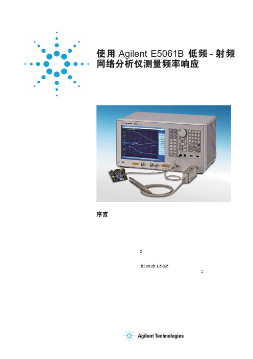
使用 Agilent E5061B 低频-射频网络分析仪测量频率响应应用指南序言测量元器件和电路的频率响应特性是确保电子设备性能的关键步骤。
汽车、医疗设备、航空航天与国防行业对电子设备的可靠性要求极高,因此在从低频至高频的各种频率范围内对各类元器件和电路进行测量非常必要。
在这些应用中,低频网络分析仪在确保低频模拟电路器件(例如传感器系统和电源部件)实现稳定可靠工作方面具有重要作用。
为此,您需要在了解射频网络分析(S 参数测量)的同时,也需要很好地对低频网络分析(增益相位测量)的应用有所了解。
本应用指南通过对 E5061B LF-RF 网络分析仪的介绍,阐述了有关低频网络分析的基础原理。
我们在此主要介绍简单的低频 2 端口器件测量,以及高阻抗探测技术和大衰减测量等相关主题。
目录E5061B-3L5 LF-RF 网络分析仪 (3)基本测量配置 (4)50 Ω被测器件 (5)非 50 Ω被测器件,实例 1 (5)非 50 Ω被测器件,实例 2 (7)使用探头在电路板上直接进行测量 (8)低频测量的 IFBW 设置 (10)使用高阻抗探头的测量方法 (11)做比值测量时对信号的分离 (13)在低频范围内测量大衰减器件 (15)运算放大器测量实例 (20)闭环增益 (20)开环增益,相位裕量 (22)CMRR (27)PSRR (29)输出阻抗 (31)参考文献 (33)表 1.测试端口选择指南23E5061B-3L5 LF-RF 网络分析仪包含选件 3L5 的 E5061B 矢量网络分析仪具有很宽的频率测量范围,从 5 Hz 至 3 GHz 。
E5061B-3L5 包括 S 参数测试端口(5 Hz 至 3 GHz ,Z in = 50 Ω)和增益相位测试端口(5 Hz 至 30 MHz ,Z in = 1 M Ω/50 Ω)。
两种测试端口都可以用于低频器件的测试(取决于测量需求)。
表 1 举例说明了怎样选择使用这两种测试端口。
agilent信号分析仪操作步骤.doc
Agilent信号分析仪操作步骤1,矢量信号分析仪功能进入出现频率设置界面设置中心频率:双击center旁边的数字,在弹出的窗口设置频率和单位。
设置扫宽:双击Span旁边的数字,一般都将其设置为8Mhz设置range 单击range旁边的数字按向下键将波形图调至中心位置。
(-20dbm左右)选择菜单中的MeasSetup——Demodulator——Digital Demod。
进入数字信号分析功能。
选择图形个数查看星座图(双击左侧绿色方框,在弹出的对话框中选择constellation)查看I眼图(双击左侧绿色方框,在弹出的对话框中选择I-Eye)查看Q眼图(双击左侧绿色方框,在弹出的对话框中选择Q-Eye)进入扫频仪后界面如下设置起始频率,选择功能键Stop Freq设置终止频率,选择Center Freq设置中心频率。
按控制面板上的SPAN x Scale键出现如下界面,选择功能键Span设置扫宽按控制面板上的AMPTD y Scale键出现如下界面,选择功能键More 1of2选择Y Axis Unit 设置电平的单位。
按控制面板上的Trace Delecter键,选择功能键盘Trace Average后出现平滑的曲线。
按控制面板上的Input/Output键,选择功能键RF Input [AC,50欧],选择75欧。
按控制面板上的BW键,出现如下界面。
分别对RBW和VBW进行设置使曲线接近平滑,建议RBW设置为500-600khz左右,VBW设置为20khz左右,这样兼顾了曲线的平滑与扫频的速度。
按控制面板上的Maker 键后输入频率与单位,设置游标。
按控制面板上的Maker Function后可以选择有一定带宽范围的游标,出现如下界面。
选择功能键Band/Interval Density。
选择功能键Band Adjust调整宽度,如需关闭选择Maker Function Off。
Agilent Technologies PSA 和 ESA 系列光谱分析仪一键测量功能指南说明书
User’s and Programmer’s ReferenceVolume 2One-Button Power Measurements PSA and ESA Series Spectrum Analyzers Refer to Volume 1 for core spectrum analyzer information.This manual provides documentation for the following instruments:Agilent Technologies PSA SeriesE4443A (3 Hz - 6.7 GHz)E4445A (3 Hz - 13.2 GHz)E4440A (3 Hz - 26.5 GHz)E4447A (3 Hz - 42.98 GHz)E4446A (3 Hz - 44.0 GHz)E4448A (3 Hz - 50.0 GHz)Agilent Technologies ESA-E SeriesE4402B (9kHz - 3.0GHz)E4404B (9kHz - 6.7GHz)E4405B (9kHz - 13.2GHz)E4407B (9kHz - 26.5GHz)Agilent Technologies ESA-L SeriesE4411B (9kHz- 1.5GHz)E4403B (9kHz - 3.0GHz)E4408B (9kHz - 26.5GHz)Manufacturing Part Number: E4440-90618Supersedes: E4440-90346Printed in USAMarch 2014© Copyright 1999-2014 Agilent Technologies, Inc..Legal InformationThe information contained in this document is subject to change without notice.Agilent Technologies makes no warranty of any kind with regard to this material, including but not limited to, the implied warranties of merchantability and fitness for a particular purpose. Agilent Technologies shall not be liable for errors contained herein or for incidental or consequential damages in connection with the furnishing, performance, or use of this material.Where to Find the Latest InformationDocumentation is updated periodically.•For the latest information about Agilent Technologies PSA Spectrum Analyzers, including firmware upgrades and application information, please visit the following Internet URL:/find/psa•For the latest information about Agilent Technologies ESA Spectrum Analyzers, including firmware upgrades and application information, please visit the following Internet URL:/find/esa•To receive the latest updates by email, subscribe to Agilent Email Updates:/find/emailupdates•Information on preventing spectrum analyzer damage can be found at:/find/tips21. Using This DocumentAbout the User’s and Programmer’s Information. . . . . . . . . . . . . . . . . . . . . . . . . . . . . . . . . . . . . . . . . . . . . 26 What is in This Book. . . . . . . . . . . . . . . . . . . . . . . . . . . . . . . . . . . . . . . . . . . . . . . . . . . . . . . . . . . . . . . . . 26 Terms Used in This Book . . . . . . . . . . . . . . . . . . . . . . . . . . . . . . . . . . . . . . . . . . . . . . . . . . . . . . . . . . . . . 27 2. One-Button Measurement FunctionsOne - Button Measurement Functions . . . . . . . . . . . . . . . . . . . . . . . . . . . . . . . . . . . . . . . . . . . . . . . . . . . . . 30 Mode Setup (Spectrum Analysis Mode) . . . . . . . . . . . . . . . . . . . . . . . . . . . . . . . . . . . . . . . . . . . . . . . . . . . 33 Radio Std. . . . . . . . . . . . . . . . . . . . . . . . . . . . . . . . . . . . . . . . . . . . . . . . . . . . . . . . . . . . . . . . . . . . . . . . . . 33 Radio Std Setup. . . . . . . . . . . . . . . . . . . . . . . . . . . . . . . . . . . . . . . . . . . . . . . . . . . . . . . . . . . . . . . . . . . . . 45 Retain Params . . . . . . . . . . . . . . . . . . . . . . . . . . . . . . . . . . . . . . . . . . . . . . . . . . . . . . . . . . . . . . . . . . . . . . 47 Enable All Measurements. . . . . . . . . . . . . . . . . . . . . . . . . . . . . . . . . . . . . . . . . . . . . . . . . . . . . . . . . . . . . 47 Autorange of Power Setting (Remote command only). . . . . . . . . . . . . . . . . . . . . . . . . . . . . . . . . . . . . . . 48 MEASURE (Spectrum Analysis Mode) . . . . . . . . . . . . . . . . . . . . . . . . . . . . . . . . . . . . . . . . . . . . . . . . . . . 49 Command Interactions: MEASure, CONFigure, FETCh, INITiate and READ. . . . . . . . . . . . . . . . . . . . 50 Current Measurement Query (Remote Command Only) . . . . . . . . . . . . . . . . . . . . . . . . . . . . . . . . . . . . . 53 Test Current Results Against all Limits (Remote Command Only) . . . . . . . . . . . . . . . . . . . . . . . . . . . . . 53 Meas Off . . . . . . . . . . . . . . . . . . . . . . . . . . . . . . . . . . . . . . . . . . . . . . . . . . . . . . . . . . . . . . . . . . . . . . . . . . 54 Channel Power . . . . . . . . . . . . . . . . . . . . . . . . . . . . . . . . . . . . . . . . . . . . . . . . . . . . . . . . . . . . . . . . . . . . . 54 Occupied BW . . . . . . . . . . . . . . . . . . . . . . . . . . . . . . . . . . . . . . . . . . . . . . . . . . . . . . . . . . . . . . . . . . . . . . 57 Adjacent Channel Power—ACP. . . . . . . . . . . . . . . . . . . . . . . . . . . . . . . . . . . . . . . . . . . . . . . . . . . . . . . . 58 Multi-Carrier Power . . . . . . . . . . . . . . . . . . . . . . . . . . . . . . . . . . . . . . . . . . . . . . . . . . . . . . . . . . . . . . . . . 62 Power Stat CCDF . . . . . . . . . . . . . . . . . . . . . . . . . . . . . . . . . . . . . . . . . . . . . . . . . . . . . . . . . . . . . . . . . . . 64 Harmonic Distortion . . . . . . . . . . . . . . . . . . . . . . . . . . . . . . . . . . . . . . . . . . . . . . . . . . . . . . . . . . . . . . . . . 67 Burst Power . . . . . . . . . . . . . . . . . . . . . . . . . . . . . . . . . . . . . . . . . . . . . . . . . . . . . . . . . . . . . . . . . . . . . . . 70 Intermod (TOI) . . . . . . . . . . . . . . . . . . . . . . . . . . . . . . . . . . . . . . . . . . . . . . . . . . . . . . . . . . . . . . . . . . . . . 73 Spurious Emissions . . . . . . . . . . . . . . . . . . . . . . . . . . . . . . . . . . . . . . . . . . . . . . . . . . . . . . . . . . . . . . . . . 74 Spectrum Emission Mask . . . . . . . . . . . . . . . . . . . . . . . . . . . . . . . . . . . . . . . . . . . . . . . . . . . . . . . . . . . . . 75 Meas Setup (Adjacent Channel Power—ACP) . . . . . . . . . . . . . . . . . . . . . . . . . . . . . . . . . . . . . . . . . . . . . . 83 Avg Number . . . . . . . . . . . . . . . . . . . . . . . . . . . . . . . . . . . . . . . . . . . . . . . . . . . . . . . . . . . . . . . . . . . . . . . 83 Avg Mode . . . . . . . . . . . . . . . . . . . . . . . . . . . . . . . . . . . . . . . . . . . . . . . . . . . . . . . . . . . . . . . . . . . . . . . . . 84 Chan Integ BW . . . . . . . . . . . . . . . . . . . . . . . . . . . . . . . . . . . . . . . . . . . . . . . . . . . . . . . . . . . . . . . . . . . . . 84 Offset/Limits. . . . . . . . . . . . . . . . . . . . . . . . . . . . . . . . . . . . . . . . . . . . . . . . . . . . . . . . . . . . . . . . . . . . . . . 85 Meas Type . . . . . . . . . . . . . . . . . . . . . . . . . . . . . . . . . . . . . . . . . . . . . . . . . . . . . . . . . . . . . . . . . . . . . . . . 89 Optimize Ref Level . . . . . . . . . . . . . . . . . . . . . . . . . . . . . . . . . . . . . . . . . . . . . . . . . . . . . . . . . . . . . . . . . 90 Method . . . . . . . . . . . . . . . . . . . . . . . . . . . . . . . . . . . . . . . . . . . . . . . . . . . . . . . . . . . . . . . . . . . . . . . . . . . 91 Total Pwr Ref . . . . . . . . . . . . . . . . . . . . . . . . . . . . . . . . . . . . . . . . . . . . . . . . . . . . . . . . . . . . . . . . . . . . . . 94 PSD Ref. . . . . . . . . . . . . . . . . . . . . . . . . . . . . . . . . . . . . . . . . . . . . . . . . . . . . . . . . . . . . . . . . . . . . . . . . . . 95 Limit Test . . . . . . . . . . . . . . . . . . . . . . . . . . . . . . . . . . . . . . . . . . . . . . . . . . . . . . . . . . . . . . . . . . . . . . . . . 96 RRC Filter . . . . . . . . . . . . . . . . . . . . . . . . . . . . . . . . . . . . . . . . . . . . . . . . . . . . . . . . . . . . . . . . . . . . . . . . 96 Filter Alpha . . . . . . . . . . . . . . . . . . . . . . . . . . . . . . . . . . . . . . . . . . . . . . . . . . . . . . . . . . . . . . . . . . . . . . . 97 Noise Correction . . . . . . . . . . . . . . . . . . . . . . . . . . . . . . . . . . . . . . . . . . . . . . . . . . . . . . . . . . . . . . . . . . . 97 Trace/View (ACP Measurement) . . . . . . . . . . . . . . . . . . . . . . . . . . . . . . . . . . . . . . . . . . . . . . . . . . . . . . . . . 99 Spectrum . . . . . . . . . . . . . . . . . . . . . . . . . . . . . . . . . . . . . . . . . . . . . . . . . . . . . . . . . . . . . . . . . . . . . . . . . . 99 Bar Graph . . . . . . . . . . . . . . . . . . . . . . . . . . . . . . . . . . . . . . . . . . . . . . . . . . . . . . . . . . . . . . . . . . . . . . . . . 99 Combined . . . . . . . . . . . . . . . . . . . . . . . . . . . . . . . . . . . . . . . . . . . . . . . . . . . . . . . . . . . . . . . . . . . . . . . . 100 Combined View Units. . . . . . . . . . . . . . . . . . . . . . . . . . . . . . . . . . . . . . . . . . . . . . . . . . . . . . . . . . . . . . . 100 Trace . . . . . . . . . . . . . . . . . . . . . . . . . . . . . . . . . . . . . . . . . . . . . . . . . . . . . . . . . . . . . . . . . . . . . . . . . . . . 100 Meas Setup (Burst Power) . . . . . . . . . . . . . . . . . . . . . . . . . . . . . . . . . . . . . . . . . . . . . . . . . . . . . . . . . . . . . 1013Avg Number . . . . . . . . . . . . . . . . . . . . . . . . . . . . . . . . . . . . . . . . . . . . . . . . . . . . . . . . . . . . . . . . . . . . . . 101 Avg Mode . . . . . . . . . . . . . . . . . . . . . . . . . . . . . . . . . . . . . . . . . . . . . . . . . . . . . . . . . . . . . . . . . . . . . . . . 102 Average Type . . . . . . . . . . . . . . . . . . . . . . . . . . . . . . . . . . . . . . . . . . . . . . . . . . . . . . . . . . . . . . . . . . . . . 103 Threshold Lvl . . . . . . . . . . . . . . . . . . . . . . . . . . . . . . . . . . . . . . . . . . . . . . . . . . . . . . . . . . . . . . . . . . . . . 103 Meas Method . . . . . . . . . . . . . . . . . . . . . . . . . . . . . . . . . . . . . . . . . . . . . . . . . . . . . . . . . . . . . . . . . . . . . 104 Burst Width. . . . . . . . . . . . . . . . . . . . . . . . . . . . . . . . . . . . . . . . . . . . . . . . . . . . . . . . . . . . . . . . . . . . . . . 104 Optimize Ref Level. . . . . . . . . . . . . . . . . . . . . . . . . . . . . . . . . . . . . . . . . . . . . . . . . . . . . . . . . . . . . . . . . 106 Trace/View (Burst Power) . . . . . . . . . . . . . . . . . . . . . . . . . . . . . . . . . . . . . . . . . . . . . . . . . . . . . . . . . . . . . 107 RF Envelope. . . . . . . . . . . . . . . . . . . . . . . . . . . . . . . . . . . . . . . . . . . . . . . . . . . . . . . . . . . . . . . . . . . . . . 107 Combined . . . . . . . . . . . . . . . . . . . . . . . . . . . . . . . . . . . . . . . . . . . . . . . . . . . . . . . . . . . . . . . . . . . . . . . . 108 Trace . . . . . . . . . . . . . . . . . . . . . . . . . . . . . . . . . . . . . . . . . . . . . . . . . . . . . . . . . . . . . . . . . . . . . . . . . . . . 108 Meas Setup (Complementary Cumulative Distribution Function—CCDF) . . . . . . . . . . . . . . . . . . . . . . . 109 Meas BW . . . . . . . . . . . . . . . . . . . . . . . . . . . . . . . . . . . . . . . . . . . . . . . . . . . . . . . . . . . . . . . . . . . . . . . . 109 Counts . . . . . . . . . . . . . . . . . . . . . . . . . . . . . . . . . . . . . . . . . . . . . . . . . . . . . . . . . . . . . . . . . . . . . . . . . . 110 Meas Interval . . . . . . . . . . . . . . . . . . . . . . . . . . . . . . . . . . . . . . . . . . . . . . . . . . . . . . . . . . . . . . . . . . . . . 111 Optimize Ref Level . . . . . . . . . . . . . . . . . . . . . . . . . . . . . . . . . . . . . . . . . . . . . . . . . . . . . . . . . . . . . . . . 112 Display (Complementary Cumulative Distribution Function—CCDF). . . . . . . . . . . . . . . . . . . . . . . . . . . 113 Full Screen . . . . . . . . . . . . . . . . . . . . . . . . . . . . . . . . . . . . . . . . . . . . . . . . . . . . . . . . . . . . . . . . . . . . . . . 113 Store Ref Trace. . . . . . . . . . . . . . . . . . . . . . . . . . . . . . . . . . . . . . . . . . . . . . . . . . . . . . . . . . . . . . . . . . . . 113 Ref Trace. . . . . . . . . . . . . . . . . . . . . . . . . . . . . . . . . . . . . . . . . . . . . . . . . . . . . . . . . . . . . . . . . . . . . . . . . 113 Gaussian Trace . . . . . . . . . . . . . . . . . . . . . . . . . . . . . . . . . . . . . . . . . . . . . . . . . . . . . . . . . . . . . . . . . . . . 114 Preferences . . . . . . . . . . . . . . . . . . . . . . . . . . . . . . . . . . . . . . . . . . . . . . . . . . . . . . . . . . . . . . . . . . . . . . . 114 Marker (Complementary Cumulative Distribution Function—CCDF) . . . . . . . . . . . . . . . . . . . . . . . . . . 115 Select Marker . . . . . . . . . . . . . . . . . . . . . . . . . . . . . . . . . . . . . . . . . . . . . . . . . . . . . . . . . . . . . . . . . . . . . 116 Normal . . . . . . . . . . . . . . . . . . . . . . . . . . . . . . . . . . . . . . . . . . . . . . . . . . . . . . . . . . . . . . . . . . . . . . . . . . 116 Delta . . . . . . . . . . . . . . . . . . . . . . . . . . . . . . . . . . . . . . . . . . . . . . . . . . . . . . . . . . . . . . . . . . . . . . . . . . . . 117 Off. . . . . . . . . . . . . . . . . . . . . . . . . . . . . . . . . . . . . . . . . . . . . . . . . . . . . . . . . . . . . . . . . . . . . . . . . . . . . . 117 Marker Trace . . . . . . . . . . . . . . . . . . . . . . . . . . . . . . . . . . . . . . . . . . . . . . . . . . . . . . . . . . . . . . . . . . . . . 118 Marker All Off . . . . . . . . . . . . . . . . . . . . . . . . . . . . . . . . . . . . . . . . . . . . . . . . . . . . . . . . . . . . . . . . . . . . 118 Marker X Position (Remote Command Only) . . . . . . . . . . . . . . . . . . . . . . . . . . . . . . . . . . . . . . . . . . . . 119 Marker Y Position (Remote Command Only) . . . . . . . . . . . . . . . . . . . . . . . . . . . . . . . . . . . . . . . . . . . . 120 Marker Maximum and Minimum (Remote Command Only) . . . . . . . . . . . . . . . . . . . . . . . . . . . . . . . . 120 SPAN X Scale (Complementary Cumulative Distribution Function—CCDF) . . . . . . . . . . . . . . . . . . . . . 121 Scale/Div . . . . . . . . . . . . . . . . . . . . . . . . . . . . . . . . . . . . . . . . . . . . . . . . . . . . . . . . . . . . . . . . . . . . . . . . 121 Meas Setup (Channel Power—CHP) . . . . . . . . . . . . . . . . . . . . . . . . . . . . . . . . . . . . . . . . . . . . . . . . . . . . 123 Avg Number . . . . . . . . . . . . . . . . . . . . . . . . . . . . . . . . . . . . . . . . . . . . . . . . . . . . . . . . . . . . . . . . . . . . . . 123 Avg Mode . . . . . . . . . . . . . . . . . . . . . . . . . . . . . . . . . . . . . . . . . . . . . . . . . . . . . . . . . . . . . . . . . . . . . . . . 124 Integ BW . . . . . . . . . . . . . . . . . . . . . . . . . . . . . . . . . . . . . . . . . . . . . . . . . . . . . . . . . . . . . . . . . . . . . . . . 124 Chan Pwr Span . . . . . . . . . . . . . . . . . . . . . . . . . . . . . . . . . . . . . . . . . . . . . . . . . . . . . . . . . . . . . . . . . . . . 125 PSD Unit (PSA Only Setting). . . . . . . . . . . . . . . . . . . . . . . . . . . . . . . . . . . . . . . . . . . . . . . . . . . . . . . . . 126 Optimize Ref Level . . . . . . . . . . . . . . . . . . . . . . . . . . . . . . . . . . . . . . . . . . . . . . . . . . . . . . . . . . . . . . . . 126 RRC Filter . . . . . . . . . . . . . . . . . . . . . . . . . . . . . . . . . . . . . . . . . . . . . . . . . . . . . . . . . . . . . . . . . . . . . . . 126 Filter Alpha . . . . . . . . . . . . . . . . . . . . . . . . . . . . . . . . . . . . . . . . . . . . . . . . . . . . . . . . . . . . . . . . . . . . . . 128 Meas Setup (Harmonic Distortion) . . . . . . . . . . . . . . . . . . . . . . . . . . . . . . . . . . . . . . . . . . . . . . . . . . . . . . 129 Avg Number . . . . . . . . . . . . . . . . . . . . . . . . . . . . . . . . . . . . . . . . . . . . . . . . . . . . . . . . . . . . . . . . . . . . . . 129 Avg Mode . . . . . . . . . . . . . . . . . . . . . . . . . . . . . . . . . . . . . . . . . . . . . . . . . . . . . . . . . . . . . . . . . . . . . . . . 130 Harmonics . . . . . . . . . . . . . . . . . . . . . . . . . . . . . . . . . . . . . . . . . . . . . . . . . . . . . . . . . . . . . . . . . . . . . . . 130 ST/Harmonic . . . . . . . . . . . . . . . . . . . . . . . . . . . . . . . . . . . . . . . . . . . . . . . . . . . . . . . . . . . . . . . . . . . . . 131 Range Table (On/Off). . . . . . . . . . . . . . . . . . . . . . . . . . . . . . . . . . . . . . . . . . . . . . . . . . . . . . . . . . . . . . . 131 4Range Table . . . . . . . . . . . . . . . . . . . . . . . . . . . . . . . . . . . . . . . . . . . . . . . . . . . . . . . . . . . . . . . . . . . . . . 132 Optimize Ref Level . . . . . . . . . . . . . . . . . . . . . . . . . . . . . . . . . . . . . . . . . . . . . . . . . . . . . . . . . . . . . . . . 138 Trace/View (Channel Power Measurement). . . . . . . . . . . . . . . . . . . . . . . . . . . . . . . . . . . . . . . . . . . . . . . . 139 Spectrum . . . . . . . . . . . . . . . . . . . . . . . . . . . . . . . . . . . . . . . . . . . . . . . . . . . . . . . . . . . . . . . . . . . . . . . . . 139 Combined . . . . . . . . . . . . . . . . . . . . . . . . . . . . . . . . . . . . . . . . . . . . . . . . . . . . . . . . . . . . . . . . . . . . . . . . 139 Trace . . . . . . . . . . . . . . . . . . . . . . . . . . . . . . . . . . . . . . . . . . . . . . . . . . . . . . . . . . . . . . . . . . . . . . . . . . . . 139 Trace/View (Harmonic Distortion). . . . . . . . . . . . . . . . . . . . . . . . . . . . . . . . . . . . . . . . . . . . . . . . . . . . . . . 141 Harmonics . . . . . . . . . . . . . . . . . . . . . . . . . . . . . . . . . . . . . . . . . . . . . . . . . . . . . . . . . . . . . . . . . . . . . . . 141 Harmonics & THD . . . . . . . . . . . . . . . . . . . . . . . . . . . . . . . . . . . . . . . . . . . . . . . . . . . . . . . . . . . . . . . . . 141 Meas Setup (Intermod (TOI)). . . . . . . . . . . . . . . . . . . . . . . . . . . . . . . . . . . . . . . . . . . . . . . . . . . . . . . . . . . 143 Avg Number . . . . . . . . . . . . . . . . . . . . . . . . . . . . . . . . . . . . . . . . . . . . . . . . . . . . . . . . . . . . . . . . . . . . . . 143 Avg Mode . . . . . . . . . . . . . . . . . . . . . . . . . . . . . . . . . . . . . . . . . . . . . . . . . . . . . . . . . . . . . . . . . . . . . . . . 144 TOI Span. . . . . . . . . . . . . . . . . . . . . . . . . . . . . . . . . . . . . . . . . . . . . . . . . . . . . . . . . . . . . . . . . . . . . . . . . 144 Max Mixer Lvl . . . . . . . . . . . . . . . . . . . . . . . . . . . . . . . . . . . . . . . . . . . . . . . . . . . . . . . . . . . . . . . . . . . . 145 Optimize Ref Level. . . . . . . . . . . . . . . . . . . . . . . . . . . . . . . . . . . . . . . . . . . . . . . . . . . . . . . . . . . . . . . . . 146 Meas Setup (Multi-Carrier Power—MCP). . . . . . . . . . . . . . . . . . . . . . . . . . . . . . . . . . . . . . . . . . . . . . . . . 147 Avg Number . . . . . . . . . . . . . . . . . . . . . . . . . . . . . . . . . . . . . . . . . . . . . . . . . . . . . . . . . . . . . . . . . . . . . . 147 Avg Mode . . . . . . . . . . . . . . . . . . . . . . . . . . . . . . . . . . . . . . . . . . . . . . . . . . . . . . . . . . . . . . . . . . . . . . . . 148 Carrier Setup. . . . . . . . . . . . . . . . . . . . . . . . . . . . . . . . . . . . . . . . . . . . . . . . . . . . . . . . . . . . . . . . . . . . . . 149 Offsets/Limits . . . . . . . . . . . . . . . . . . . . . . . . . . . . . . . . . . . . . . . . . . . . . . . . . . . . . . . . . . . . . . . . . . . . . 155 Carrier Result . . . . . . . . . . . . . . . . . . . . . . . . . . . . . . . . . . . . . . . . . . . . . . . . . . . . . . . . . . . . . . . . . . . . . 158 Optimize Ref Level. . . . . . . . . . . . . . . . . . . . . . . . . . . . . . . . . . . . . . . . . . . . . . . . . . . . . . . . . . . . . . . . . 158 Method . . . . . . . . . . . . . . . . . . . . . . . . . . . . . . . . . . . . . . . . . . . . . . . . . . . . . . . . . . . . . . . . . . . . . . . . . . 159 Power Ref . . . . . . . . . . . . . . . . . . . . . . . . . . . . . . . . . . . . . . . . . . . . . . . . . . . . . . . . . . . . . . . . . . . . . . . . 160 Limit Test . . . . . . . . . . . . . . . . . . . . . . . . . . . . . . . . . . . . . . . . . . . . . . . . . . . . . . . . . . . . . . . . . . . . . . . . 160 RRC Filter . . . . . . . . . . . . . . . . . . . . . . . . . . . . . . . . . . . . . . . . . . . . . . . . . . . . . . . . . . . . . . . . . . . . . . . 161 Filter Alpha. . . . . . . . . . . . . . . . . . . . . . . . . . . . . . . . . . . . . . . . . . . . . . . . . . . . . . . . . . . . . . . . . . . . . . . 161 Noise Correction . . . . . . . . . . . . . . . . . . . . . . . . . . . . . . . . . . . . . . . . . . . . . . . . . . . . . . . . . . . . . . . . . . 162 Trace/View (Multi-Carrier Power Measurement). . . . . . . . . . . . . . . . . . . . . . . . . . . . . . . . . . . . . . . . . . . . 163 Spectrum . . . . . . . . . . . . . . . . . . . . . . . . . . . . . . . . . . . . . . . . . . . . . . . . . . . . . . . . . . . . . . . . . . . . . . . . . 163 Combined . . . . . . . . . . . . . . . . . . . . . . . . . . . . . . . . . . . . . . . . . . . . . . . . . . . . . . . . . . . . . . . . . . . . . . . . 163 Combined View Units. . . . . . . . . . . . . . . . . . . . . . . . . . . . . . . . . . . . . . . . . . . . . . . . . . . . . . . . . . . . . . . 164 Trace . . . . . . . . . . . . . . . . . . . . . . . . . . . . . . . . . . . . . . . . . . . . . . . . . . . . . . . . . . . . . . . . . . . . . . . . . . . . 164 Meas Setup (Occupied Bandwidth—OBW) . . . . . . . . . . . . . . . . . . . . . . . . . . . . . . . . . . . . . . . . . . . . . . . 165 Avg Number . . . . . . . . . . . . . . . . . . . . . . . . . . . . . . . . . . . . . . . . . . . . . . . . . . . . . . . . . . . . . . . . . . . . . . 165 Avg Mode . . . . . . . . . . . . . . . . . . . . . . . . . . . . . . . . . . . . . . . . . . . . . . . . . . . . . . . . . . . . . . . . . . . . . . . . 166 Max Hold . . . . . . . . . . . . . . . . . . . . . . . . . . . . . . . . . . . . . . . . . . . . . . . . . . . . . . . . . . . . . . . . . . . . . . . . 166 Occ BW% Pwr . . . . . . . . . . . . . . . . . . . . . . . . . . . . . . . . . . . . . . . . . . . . . . . . . . . . . . . . . . . . . . . . . . . 167 OBW Span . . . . . . . . . . . . . . . . . . . . . . . . . . . . . . . . . . . . . . . . . . . . . . . . . . . . . . . . . . . . . . . . . . . . . . . 167 x dB . . . . . . . . . . . . . . . . . . . . . . . . . . . . . . . . . . . . . . . . . . . . . . . . . . . . . . . . . . . . . . . . . . . . . . . . . . . . 168 Optimize Ref Level . . . . . . . . . . . . . . . . . . . . . . . . . . . . . . . . . . . . . . . . . . . . . . . . . . . . . . . . . . . . . . . . 169 Meas Setup (Spectrum Emissions Mask—SEM) . . . . . . . . . . . . . . . . . . . . . . . . . . . . . . . . . . . . . . . . . . . 171 Avg Number . . . . . . . . . . . . . . . . . . . . . . . . . . . . . . . . . . . . . . . . . . . . . . . . . . . . . . . . . . . . . . . . . . . . . . 171 Meas Type . . . . . . . . . . . . . . . . . . . . . . . . . . . . . . . . . . . . . . . . . . . . . . . . . . . . . . . . . . . . . . . . . . . . . . . 172 Ref Channel . . . . . . . . . . . . . . . . . . . . . . . . . . . . . . . . . . . . . . . . . . . . . . . . . . . . . . . . . . . . . . . . . . . . . . 173 Offset/Limits . . . . . . . . . . . . . . . . . . . . . . . . . . . . . . . . . . . . . . . . . . . . . . . . . . . . . . . . . . . . . . . . . . . . . 175 Results Index (PSA only) . . . . . . . . . . . . . . . . . . . . . . . . . . . . . . . . . . . . . . . . . . . . . . . . . . . . . . . . . . . . 187 Optimize Ref Level. . . . . . . . . . . . . . . . . . . . . . . . . . . . . . . . . . . . . . . . . . . . . . . . . . . . . . . . . . . . . . . . . 187 RRC Filter . . . . . . . . . . . . . . . . . . . . . . . . . . . . . . . . . . . . . . . . . . . . . . . . . . . . . . . . . . . . . . . . . . . . . . . 1875Filter Alpha . . . . . . . . . . . . . . . . . . . . . . . . . . . . . . . . . . . . . . . . . . . . . . . . . . . . . . . . . . . . . . . . . . . . . . 188 Display (Spectrum Emissions Mask—SEM) . . . . . . . . . . . . . . . . . . . . . . . . . . . . . . . . . . . . . . . . . . . . . . 189 Full Screen . . . . . . . . . . . . . . . . . . . . . . . . . . . . . . . . . . . . . . . . . . . . . . . . . . . . . . . . . . . . . . . . . . . . . . . 189 Limit Display . . . . . . . . . . . . . . . . . . . . . . . . . . . . . . . . . . . . . . . . . . . . . . . . . . . . . . . . . . . . . . . . . . . . . 189 Preferences . . . . . . . . . . . . . . . . . . . . . . . . . . . . . . . . . . . . . . . . . . . . . . . . . . . . . . . . . . . . . . . . . . . . . . . 189 Marker (Spectrum Emissions Mask—SEM) . . . . . . . . . . . . . . . . . . . . . . . . . . . . . . . . . . . . . . . . . . . . . . . 191 Select Marker . . . . . . . . . . . . . . . . . . . . . . . . . . . . . . . . . . . . . . . . . . . . . . . . . . . . . . . . . . . . . . . . . . . . . 191 Normal . . . . . . . . . . . . . . . . . . . . . . . . . . . . . . . . . . . . . . . . . . . . . . . . . . . . . . . . . . . . . . . . . . . . . . . . . . 192 Off. . . . . . . . . . . . . . . . . . . . . . . . . . . . . . . . . . . . . . . . . . . . . . . . . . . . . . . . . . . . . . . . . . . . . . . . . . . . . . 192 Trace/View (Spectrum Emissions Mask). . . . . . . . . . . . . . . . . . . . . . . . . . . . . . . . . . . . . . . . . . . . . . . . . . 193 Abs Pwr & Freq . . . . . . . . . . . . . . . . . . . . . . . . . . . . . . . . . . . . . . . . . . . . . . . . . . . . . . . . . . . . . . . . . . . 193 Rel Pwr & Freq . . . . . . . . . . . . . . . . . . . . . . . . . . . . . . . . . . . . . . . . . . . . . . . . . . . . . . . . . . . . . . . . . . . 193 Integrated Power. . . . . . . . . . . . . . . . . . . . . . . . . . . . . . . . . . . . . . . . . . . . . . . . . . . . . . . . . . . . . . . . . . . 194 SPAN X Scale (Spectrum Emissions Mask—SEM) . . . . . . . . . . . . . . . . . . . . . . . . . . . . . . . . . . . . . . . . . 195 Scale/Div. . . . . . . . . . . . . . . . . . . . . . . . . . . . . . . . . . . . . . . . . . . . . . . . . . . . . . . . . . . . . . . . . . . . . . . . . 195 Ref Value. . . . . . . . . . . . . . . . . . . . . . . . . . . . . . . . . . . . . . . . . . . . . . . . . . . . . . . . . . . . . . . . . . . . . . . . . 195 Ref Position. . . . . . . . . . . . . . . . . . . . . . . . . . . . . . . . . . . . . . . . . . . . . . . . . . . . . . . . . . . . . . . . . . . . . . . 196 Meas Setup (Spurious Emissions) . . . . . . . . . . . . . . . . . . . . . . . . . . . . . . . . . . . . . . . . . . . . . . . . . . . . . . . 197 Avg Number . . . . . . . . . . . . . . . . . . . . . . . . . . . . . . . . . . . . . . . . . . . . . . . . . . . . . . . . . . . . . . . . . . . . . . 197 Avg Mode . . . . . . . . . . . . . . . . . . . . . . . . . . . . . . . . . . . . . . . . . . . . . . . . . . . . . . . . . . . . . . . . . . . . . . . . 197 Range Table . . . . . . . . . . . . . . . . . . . . . . . . . . . . . . . . . . . . . . . . . . . . . . . . . . . . . . . . . . . . . . . . . . . . . . 198 Meas Type . . . . . . . . . . . . . . . . . . . . . . . . . . . . . . . . . . . . . . . . . . . . . . . . . . . . . . . . . . . . . . . . . . . . . . . 211 Spur . . . . . . . . . . . . . . . . . . . . . . . . . . . . . . . . . . . . . . . . . . . . . . . . . . . . . . . . . . . . . . . . . . . . . . . . . . . . 212 Ref Level . . . . . . . . . . . . . . . . . . . . . . . . . . . . . . . . . . . . . . . . . . . . . . . . . . . . . . . . . . . . . . . . . . . . . . . . 213 Fast Spurious Meas . . . . . . . . . . . . . . . . . . . . . . . . . . . . . . . . . . . . . . . . . . . . . . . . . . . . . . . . . . . . . . . . 213 Display (Spurious Emissions) for PSA Only. . . . . . . . . . . . . . . . . . . . . . . . . . . . . . . . . . . . . . . . . . . . . . . 215 Full Screen . . . . . . . . . . . . . . . . . . . . . . . . . . . . . . . . . . . . . . . . . . . . . . . . . . . . . . . . . . . . . . . . . . . . . . . 215 Preferences . . . . . . . . . . . . . . . . . . . . . . . . . . . . . . . . . . . . . . . . . . . . . . . . . . . . . . . . . . . . . . . . . . . . . . . 215 Marker (Spurious Emissions) for PSA Only . . . . . . . . . . . . . . . . . . . . . . . . . . . . . . . . . . . . . . . . . . . . . . . 217 Select Marker . . . . . . . . . . . . . . . . . . . . . . . . . . . . . . . . . . . . . . . . . . . . . . . . . . . . . . . . . . . . . . . . . . . . . 217 Normal . . . . . . . . . . . . . . . . . . . . . . . . . . . . . . . . . . . . . . . . . . . . . . . . . . . . . . . . . . . . . . . . . . . . . . . . . . 218 Delta . . . . . . . . . . . . . . . . . . . . . . . . . . . . . . . . . . . . . . . . . . . . . . . . . . . . . . . . . . . . . . . . . . . . . . . . . . . . 218 Off. . . . . . . . . . . . . . . . . . . . . . . . . . . . . . . . . . . . . . . . . . . . . . . . . . . . . . . . . . . . . . . . . . . . . . . . . . . . . . 219 Markers All Off. . . . . . . . . . . . . . . . . . . . . . . . . . . . . . . . . . . . . . . . . . . . . . . . . . . . . . . . . . . . . . . . . . . . 219 Marker Mode . . . . . . . . . . . . . . . . . . . . . . . . . . . . . . . . . . . . . . . . . . . . . . . . . . . . . . . . . . . . . . . . . . . . . 220 3. Menu Maps:One-Button Measurement FunctionsOne-Button Measurement Menu Maps . . . . . . . . . . . . . . . . . . . . . . . . . . . . . . . . . . . . . . . . . . . . . . . . . . . 222 Directions for Use . . . . . . . . . . . . . . . . . . . . . . . . . . . . . . . . . . . . . . . . . . . . . . . . . . . . . . . . . . . . . . . . . 223 MEASURE Key . . . . . . . . . . . . . . . . . . . . . . . . . . . . . . . . . . . . . . . . . . . . . . . . . . . . . . . . . . . . . . . . . . . 224 Meas Control Key . . . . . . . . . . . . . . . . . . . . . . . . . . . . . . . . . . . . . . . . . . . . . . . . . . . . . . . . . . . . . . . . . 225 Mode Setup Key for ESA . . . . . . . . . . . . . . . . . . . . . . . . . . . . . . . . . . . . . . . . . . . . . . . . . . . . . . . . . . . 226 Mode Setup Key for PSA (1 of 3) . . . . . . . . . . . . . . . . . . . . . . . . . . . . . . . . . . . . . . . . . . . . . . . . . . . . . 227 Mode Setup Key for PSA (2 of 3) . . . . . . . . . . . . . . . . . . . . . . . . . . . . . . . . . . . . . . . . . . . . . . . . . . . . . 228 Mode Setup Key for PSA (3 of 3) . . . . . . . . . . . . . . . . . . . . . . . . . . . . . . . . . . . . . . . . . . . . . . . . . . . . . 229 ACP Measurement: Meas Setup Key . . . . . . . . . . . . . . . . . . . . . . . . . . . . . . . . . . . . . . . . . . . . . . . . . . 230 ACP Measurement: Trace/View Key . . . . . . . . . . . . . . . . . . . . . . . . . . . . . . . . . . . . . . . . . . . . . . . . . . . 231 Burst Power Measurement: Meas Setup Key . . . . . . . . . . . . . . . . . . . . . . . . . . . . . . . . . . . . . . . . . . . . 232 6。
安捷伦网络分析仪使用手册
网络分析仪使用手册目录ACTIVE CH/TRACE Block:Channel Prev:选择上一个通道 Channel Next:选择下一个通道Trace Prev:选择上一个轨迹 Trace Next: 选择下一个轨迹RESPONSE Block:Channel Max:通道最大化Trace Max: 轨迹最大化Meas:设置S参数Format:设置格式Scale:设置比例尺Display:设置显示参数Avg: 波形平整Cal: 校准STIMULUS Block:Start:设置频段起始位置Stop:设置频段截止位置Center: 设置频段中心位置Span: 设置频段范围Sweep Setup:扫描设置Trigger:触发NAVIGATION Block: Enter:确定ENTRY Block:Entry off: 取消当前窗口Back space:退格键Focus: 窗口切换键+/—:正负切换键G/n, M/,k/m: 单位输入INSTR STATE Block:Macro Setup:Macro Run:Macro Break:Save/Recall:程序载入载出键 System: 系统功能键Preset: 预设置键MKR/ANALYSIS Block:Marker: 标记键Marker Search: 标记设置键Marker Fctn:标记功能Analysis:分析部分按键详细功能:——-—-——-----—-————---—-———-——----———-———-———---—-——-—-———-—-System:(系统功能设定)Print: 将显示屏画面打印出来Abort printing: 终止打印Printer setup: 配置打印机Invert image:颠倒图象颜色Dump screen image:将显示屏画面保存到硬盘中E5091A setup: 略Misc setup: 混杂功能Beeper: 发声控制Beeper complete: 开/关提示音Test beeper complete: 测试开/关提示音Beep warning: 开/关警告音Test beep warning: 测试开/关警告音Return: 返回GPIB setup:略Network setup:略Clock setup: 时钟设定Set date and time: 设置日期和时间Show clock: 开/关时间显示Return: 返回Key lock:锁定功能Front panel & keyboard lock: 锁定前端面板和键盘Touch screen & mouse lock: 锁定触摸屏和鼠标Return: 返回Color setup:颜色设定Normal:设置普通模式下的颜色设定Data trace1:对数据轨迹1进行颜色设定Red:调整数据轨迹1红色分量的大小Green: 调整数据轨迹1绿色分量的大小Blue: 调整数据轨迹1蓝色分量的大小Return: 返回Data trace2—Data trace 9:数据轨迹2到数据轨迹9的颜色设定方法同数据轨迹1Mem trace1—Mem trace 9:记忆轨迹1到记忆轨迹9的颜色设定方法同数据轨迹1Graticule main:调整方格标签和外部筐架的颜色设定(设定方法同前)Graticule sub:调整方格线的颜色设定(设定方法同前)Limit fail: 调整限制测试中失败标签的颜色设定(设定方法同前)Limit line: 调整限制线的颜色(设定方法同前)Background:调整背景颜色(设定方法同前)Reset color:使用默认颜色设置Return:返回Invert:设置颠倒颜色后的颜色设置Return:返回Channel trace setup:略Control panel:略Return: 返回Backlight: 略Firmware revision:略Service menu:略Return:返回-———---—-———--——--—-—-—————-————---——-—-—-—-——-Trigger:(触发设定)Hold: 当前通道停止扫描Single:进行一次扫描后停止Continuous:连续扫描Hold all channels: 所有通道停止扫描Continuous disp channels:对所有通道进行连续扫描Trigger source: 略Restart:终止一次扫描Trigger:略Return: 返回-———-——-—--—-—-—————-—-—-—--———----——-—---—-———Marker: (标记设定)Maker 1:激活标记1,并出现窗口设置其值Maker 2:激活标记2,并出现窗口设置其值Maker 3:激活标记3,并出现窗口设置其值Maker 4: 激活标记4,并出现窗口设置其值More markers:更多的标记Maker 5—9:用法同前Return: 返回Ref marker: 激活参考标记,并出现窗口设置其激励值Clear marker menu: 清除标记菜单All off: 全部清除Maker 1: 清除标记1Maker 2—9:同上Ref marker: 清除参考标记Return:返回Maker → Ref marker: 将激活标记设置成参考标记Ref marker mode:设置为参考标记模式Return: 返回——------———————--—-——-—--——-------———————--————Marker Fctn:(标记功能设定)Marker → start:设定标记的起始激励值Marker → stop: 设定标记的截止激励值Marker → center:设定标记的中心激励值Marker → reference:略Marker → delay: 略Discrete:略Couple: 略Marker table: 调出标记列表Statistics:显示三项统计数据Return: 返回--——————--—---———-——-——--———-—-—--—--—————---——Marker search:(标记搜索设定)Max:将标记移到其轨迹上的最大点Min:将标记移到其轨迹上的最小点Peak:峰值功能Search peak: 寻找顶峰Search left:在左侧寻找顶峰Search right: 在右侧寻找顶峰Peak excursion:设置顶峰偏移Peak polarity:极性设置Positive:正极性Negative:负极性Both: 双极性Cancel: 取消Return:返回Target:目标搜索功能Search target: 寻找目标Search left:向左寻找目标Search right:向右寻找目标Target value:设定目标值Target transition: 根据变化趋势寻找目标Positive: 正向搜索Negative: 负项搜索Both:双向搜索Cancel: 取消Return:返回Tracking:跟踪Search range:搜索范围菜单Search range: 关闭或开启局部搜索功能Start:设定搜索范围起始频率Stop: 设定搜索范围截至频率Couple:略Return:返回Bandwidth: 关闭或开启带宽搜索功能Bandwidth value: 设定带宽值Return:返回——-—--——-————--——---———-—-—--—--——-----—----—-—Meas:(s参数的设定)S11: 1端口发1端口收S12: 1端口发2端口收S21: 2端口发1端口收S22: 2端口发2端口收Return: 返回注:以上收发均针对网络测试仪而言,对被测产品来说刚好相反-———-———-——-—--—-———--———---———-—————-——---—--- Scale:( 刻度标尺的设定)Auto scale:自动调整刻度标尺Auto scale all: 对所有自动调整标尺Divisions:设定格子的个数 (必须为偶数个)Scale/Div: 设定每格所代表的值Reference position: 确定参考线位置Reference value: 设定参考线值Marker reference:将当前激活标记的响应值设为参考线Electrical delay: 对激活的轨迹设置一个延迟Phase offset:测试相位时添加相位偏移Return:返回--———--—-———-—--—---—--—-—----———-————-———-—-—- Save/Recall:(保存,装载设定)Save state: 存储当前状态State01—state08:将当前状态存于状态01到状态08Autorec: 以Autorec为文件名将当前状态储存于硬盘中File dialog: 以任意文件名将当前状态保存于硬盘中Return: 返回Recall state:装载已保存状态State01-state08:装载状态01到状态08Autorec: 装载以文件名Autorec保存的状态File dialog:装载以其它文件名保存的状态Return:返回Save channel:State A – State D:将当前所有通道设定保存到状态A到D中Clear states: 清除所有通道设定记录Ok:确定Cancel: 取消Return:返回Recall channel:装载通道设定State A – State D: 将状态A到D中保存的通道设定装载出来Return: 返回Save type:设定存储类型State only:只保存设定数据State & Cal: 保存设定和校验数据State & Trace:保存设定和轨迹数据All:保存所有数据Cancel:取消Channel/Trace: 略Save trace data:保存轨迹数据Explore.。
Agilent安捷伦功率器件分析仪-操作指导说明
Scale:选择曲线显示格式
Anode:二极管正极接电流源(依据
规格书测试条件合理选择,大于 1A
VF 测试-方法二
则需要选择 HC 通道) VfStart:开始电压
3.2 3.2 参数设置
VfStop:结束电压 VfStep:每个测试点电压间隔值
均有“Force”和“Sence”双孔,实 际内部相当于短路,即通过双线并 绕以降低测试误差; 应用 HC 模块时,下方 low 双孔默认 接地即可; 可看成将 HP/HC/HV 作为电源正极, GNDU1 作为电源负极
Agilent 安捷伦功率器件分析仪-操作指导说明
测试台说明: 2.2
2.2 接线模块
2.3 数据读取
▷ 点击“ ”启动测试;
完成测试后点击自动刻度; List Display 下拉数据,可以查看每个
Vr 下的反向漏电流 Ir,一般 Ir=250μA 时对应的最小 Vr 作为击穿电压
Agilent 安捷伦功率器件分析仪-操作指导说明
VF 测试 3.1
3.1 连线
按测试电路原理图,正确连接各接线柱。
IfSpec@Vf:自动读取所设正向电流
下对应的正向压降
Agilent 安捷伦功率器件分析仪-操作指导说明
▷ 点击“ ”启动测试;
完成测试后点击自动刻度;
VF 测试-方法一 List Display 下拉数据,可以查看每个
3.3
If 下的正向压降 Vf
3.3 数据读取
Agilent 安捷伦功率器件分析仪-操作指导说明
依 次 从 Application Test 选 择 PowerDiode,再选择 Ir-Vr 测试模块:
VR/IR 测试 2.2
- 1、下载文档前请自行甄别文档内容的完整性,平台不提供额外的编辑、内容补充、找答案等附加服务。
- 2、"仅部分预览"的文档,不可在线预览部分如存在完整性等问题,可反馈申请退款(可完整预览的文档不适用该条件!)。
- 3、如文档侵犯您的权益,请联系客服反馈,我们会尽快为您处理(人工客服工作时间:9:00-18:30)。
仪器仪表的技术性能及指标假设带宽为10Hz,用85032F校准箱校准,运行环境温度为23℃±5℃,与校准温度差值<1℃且测量数据不取平均。
系统阻抗:50Ω;频率范围:300KHz~1.5GHz;最大功率:10dBm;最小功率(不加衰减器):-45dBm(-5dBm);系统动态范围(不加衰减器):115dB(300kHz~1MHz),120dB(1MHz~3GHz)扫描类型:线性,幂,对数,分段波道数:4每波道轨迹数:4显示器:10.4英寸彩色LCD显示器操作规范使用者要爱护仪器,确保文明使用。
1)开机前确保稳压电源及仪器地线的正确连接。
2)使用中不得接触仪器接头内芯(含连接电缆)3)使用时不允许工作台有较大振动。
4)使用中不能随意切断电源,造成不正常关机。
不能频繁开关机。
5)使用射频电缆时不要用力大,确保电缆保持较大的弧度。
用毕电缆接头上加接头盖。
6)旋接接头时,要旋接头的螺套,尽量确保内芯不旋转。
7)尽量协调、少用校准件。
校准件用毕必须加盖放回器件盒。
8)转接件用毕应加盖后放回盒中。
9)停用时必须关机,关闭稳压电源,方可打扫卫生。
7、使用细则一、按左下方的电源键启动矢量网络分析仪,启动后,待仪器完成自检后进入启动界面。
初始状态的默认值如下:起始频率----300KHz终止频率----1.5GHz端口输出功率----0dBm测量点数----201个轨迹代表的测量值----S21显示格式----dBMAG参考电平----0dB参考线位置----第8格二、起始状态设置:1功率电平设定㈠按“POWER/BW/AVG”键,进入“功率/测量带宽/平均值设置”菜单㈡按“POWER”键-数字键-单位键完成功率电平设定。
如:“POWER”键-0-X1,即设定功率电平为0dBm。
,“-”为随后之意。
注意功率设定不得超出仪器提示范围(本仪器的范围是-45dBm到+10dBm),否则无效。
无源器件调试与检验推荐功率设定为0dBm(仪器的默认值0dBm),有源器件的测试建议功率设置小于-20dBm。
2设置仪器测量频带起止频点法:按START/CENTER或CENTER/SPAN键,进入频率设置菜单。
㈠按“Start”-数字键-单位键,设定起始频点。
如:按“Start”键-800-M/μ,即完成起始频点为800MHz的设置。
㈡按“Stop”键-数字键-单位键,设定终止频点。
如:按“Stop”键-0.920-G/n,即完成终止频点为0.92Ghz/920MHz的设置。
注意:一般设定时要求起点频率小于终止频率,否则设定无效。
中心频带加带宽法:按START/CENTER或CENTER/SPAN键,进入频率设置菜单。
㈠按“Center”键-数字键-单位键,设定频带中心频点。
㈡按“Span”键-数字键-单位键,设定频带带宽。
3添加轨迹(Trace)测量的数据(如S11、S21、S12、S22)是通过轨迹(Trace)在屏幕上显示出来的,每条轨迹对应的属性在屏幕的左上方显示,每条轨迹的属性有5个部分,其详细的解释如下:Trc1:轨迹名称,用户可以自行修改为任意字符串S21:当前轨迹代表的测量值,可选择S11、S21、S12、S22等等dBMag:当前轨迹的显示格式,可选择dBMag、Phase、Smith、Polar等10dB:屏幕上垂直方向的每个方格代表的尺度Ref0dB:参考线(图中右边有一个三角形的虚线)对应的数值快捷键:在不同轨迹之间切换,可以用右上方“←”或“→”键,进行切换。
本仪表可以在同一个窗口中显示多条轨迹,也可以在多个窗口中分别显示不同的轨迹,下面分别描述两种显示方式的设置。
㈠在同一个屏幕显示多个轨迹:(1)按TRACESELECT键激活轨迹设置菜单。
(2)按“AddTrace”系统会自动添加第二条轨迹,默认的名字为“Trc2”并且系统会自动给每个轨迹分配不同的颜色,当前激活的轨迹,在显示区域其背景是灰白色的。
(3)在上述的任意5个属性的显示区域上面,点击鼠标右键,即可更改该轨迹对应的属性。
㈡在多个窗口中分别显示不同的轨迹:(1)按“TRACESELECT”键激活轨迹设置菜单。
(2)按“AddTrace+DiagArea”系统会自动添加第二个窗口,并在第二个窗口中显示第二条轨迹,默认的名字为“Trc2”。
(3)在上述的任意5个属性的显示区域上面,点击鼠标右键,即可更改该轨迹对应的属性。
4仪器的校准仪器在进行测量之前要进行校准,或者调出以前校准的数据,一旦测试条件变化(如温度、环境、测试电缆发生变化),都要进行重新校准,校准的类型有很多种,本文以2端口的TOSM校准为例。
(1)按CAL键激活校准菜单(2)按“StartCal”键进入下一级校准菜单(3)按“Two-PortP1P2”键选择2端口校准,并进入下一级菜单(4)按“TOSM”键选择TOSM校准方式,这是会弹出对话框,选择正确的接头形式(Connector),注意这里的接头指的是测试电缆的接头形式,不是标准件的接头形式,以及正确的校准件(CalibrationKit)的型号。
(5)点击“Next”键,进入校准菜单,TOSM校准共有7个步骤:①在1端口接开路校准件,用鼠标点击“Open”,结束后仪器会发出“滴”的声响,并且“Open”前面的方框会打上钩。
②在1端口接短路校准件,用鼠标点击“Short”,结束后仪器会发出“滴”的声响,并且“Short”前面的方框会打上钩。
③在1端口接负载校准件,用鼠标点击“Load”,结束后仪器会发出“滴”的声响,并且“Load”前面的方框会打上钩。
④在2端口接开路校准件,用鼠标点击“Open”,结束后仪器会发出“滴”的声响,并且“Open”前面的方框会打上钩。
⑤在2端口接短路校准件,用鼠标点击“Short”,结束后仪器会发出“滴”的声响,并且“Short”前面的方框会打上钩。
⑥在2端口接负载校准件,用鼠标点击“Load”,结束后仪器会发出“滴”的声响,并且“Load”前面的方框会打上钩。
⑦在1端口和2端口之间接直通校准件,用鼠标点击“Through”,结束后仪器会发出两声“滴”的声响,并且“Through”前面的方框会打上钩,同时下方的“Apply”键也生效。
点击“Apply”,使校准数据生效。
5保存设置本仪表可以把用户当前的设置保存到硬盘,以便以后使用,这些设置包含:起始频率、终止频率、测量点数、输出功率,还有当前的校准数据。
下次开机时可以直接调用,而不需重新设置和校准。
①点击“File/Save”菜单,在文件名对话框(FileName)里输入文件名即可。
②可以看见在在文件名对话框(FileName)右方有一个图标,点击这个图标就可以调出“软键盘”(On-screenkeyboard),可以输入字符。
③选择路径,并点击“Save”键即可保存设置。
6调出设置点击“File/Open”菜单,选择对应的设置文件,并点击“Open”键调出已保存的设置7保存图片本仪表可以把当前屏幕上显示的测量结果保存为计算机可以识别的文件格式。
点击“File/Save”菜单,在文件名对话框(FileName)里输入文件名,并选择路径,点击“Save”键即可保存图片。
8标记点(Marker)操作本仪表可以在轨迹上添加标记点(Marker),可以读出标记点对应的测量数据。
并可以设置多个标记点,还可以搜索最大值、最小值等等。
8.1设置DeltaMarker:①按Marker键,激活Marker菜单②按“RefMarker”键设置参考标记点(RefMarker),③按“Markerx”键开启Markerx,④按“DeltaMode”键,把当前选中的Markerx设为Delta模式,本仪表可以把每一个Marker都设成Delta模式,即先选中Markerx(用软键盘“Markerx”来选定,Markerx被选定之后,屏幕的Marker显示区域,会在Markerx前面用圆点?表示),然后把Markerx设置为DeltaMarker,同时在Markx的前方会出现一个三角形?标志,此时,Markerx后面的读数为Markerx 和参考Marker之间频率和读数的差值。
8.2指定范围内搜索极值点:本仪表除了能搜索整个频段内的最大/最小点,还可以在指定的频率范围内搜索极值点:①按“Search/More/SearchRange”,弹出搜索范围设置对话框。
②在Marker栏目中选择Markerx,如果此时Markerx还没有开启,则选择后面的“ON”同时开启Markerx,③在SearchRange栏目中选定范围代号,ZVB允许用户自定义10个频率范围,并且把Markerx分配到任意范围内。
④在Start和Stop栏目中设定当前范围(Rangex)的起始和终止频率。
⑤按“Search/MaxSearch或MinSearch”,即可在指定范围内搜索极值点。
9限制线的设置为了方便调试和生产测试,本仪表提供限制线功能,可以在屏幕上显示限制线,同时显示是否通过。
限制线的设置如下:(1)按“Lines/DefineLimitLine”键,弹出限制线设置对话框(2)点击“AddSegment”按钮,添加第一段限制线(3)设置限制线:Type—设置该限制线是上限(Upper)还是下限(Lower);StartStimulus—该段限制线的起始频率;StopStimulus—该段限制线的终止频率;StartResponse—该段限制线起始频率点对应的纵坐标值;StopResponse—该段限制线终止频率点对应的纵坐标值;(4)继续添加第二段、第三段等等,设置同上(5)点击“Close”按钮,关闭对话框(6)按“ShowLimitLine”键,屏幕上会显示出红色的限制线(7)按“LimitCheck”键,屏幕上会显示使测试结果是否通过限制(Pass/Fail)10分段扫描设置在做双工器、滤波器测试时,在测试带外响应为了有较高的动态范围和稳定的测试结果,需要较窄的测量带宽和较高的源输出功率,但是测量带宽设置太窄会降低扫描速度;而在测试带内响应时,可以设置较宽的测量带宽,加快测试速度。
因此为了提高测试的动态范围而又不影响速度,有必要进行分段扫描,根据测量的需求,每段采用不同的点数(Points)、源输出功率(Power)、测量带宽(Bandw)。
(1)按“Sweep/SweepType”,打开扫描设置功能菜单,这里可以设置扫描方式,如线性频率扫描、对数频率扫描、功率扫描和分段扫描等等。
(2)首先要定义分段扫描的参数,按“DefineSegments”键,弹出分段扫描设置对话框。
(3)在“Power”和“MeasBandwidth”前面打上钩。