一种轴向磁通永磁电机的设计
使用由PCB迹线制成的电磁线圈来制造轴向磁通电动机
使用由PCB迹线制成的电磁线圈来制造轴向磁通电
动机
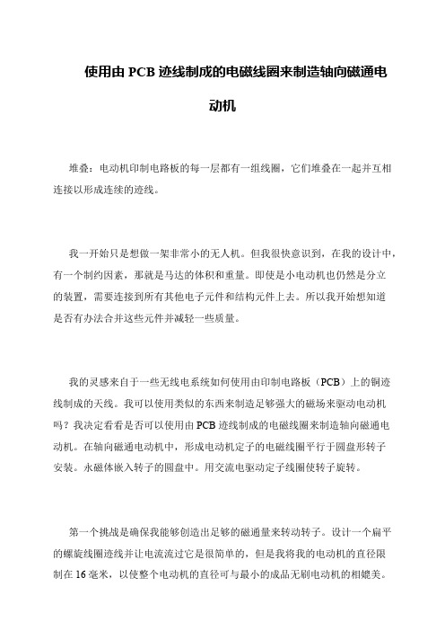
堆叠:电动机印制电路板的每一层都有一组线圈,它们堆叠在一起并互相连接以形成连续的迹线。
我一开始只是想做一架非常小的无人机。
但我很快意识到,在我的设计中,有一个制约因素,那就是马达的体积和重量。
即使是小电动机也仍然是分立
的装置,需要连接到所有其他电子元件和结构元件上去。
所以我开始想知道
是否有办法合并这些元件并减轻一些质量。
我的灵感来自于一些无线电系统如何使用由印制电路板(PCB)上的铜迹线制成的天线。
我可以使用类似的东西来制造足够强大的磁场来驱动电动机吗?我决定看看是否可以使用由PCB迹线制成的电磁线圈来制造轴向磁通电
动机。
在轴向磁通电动机中,形成电动机定子的电磁线圈平行于圆盘形转子
安装。
永磁体嵌入转子的圆盘中。
用交流电驱动定子线圈使转子旋转。
第一个挑战是确保我能够创造出足够的磁通量来转动转子。
设计一个扁平的螺旋线圈迹线并让电流流过它是很简单的,但是我将我的电动机的直径限
制在16毫米,以使整个电动机的直径可与最小的成品无刷电动机的相媲美。
基于maxwell的轴向磁通永磁同步电机电磁设计
基于maxwell的轴向磁通永磁同步电机电磁设计Maxwell方程组是电磁学中的基本方程组,它描述了电磁场的本质和规律。
在电机设计中,Maxwell方程组也是不可或缺的工具。
本文将基于Maxwell方程组,探讨轴向磁通永磁同步电机的电磁设计。
轴向磁通永磁同步电机是一种新型的永磁同步电机,它的磁通方向与轴向一致。
相比于传统的永磁同步电机,轴向磁通永磁同步电机具有更高的功率密度和效率。
在电磁设计中,需要考虑电机的磁路和电路两个方面。
首先,考虑电机的磁路设计。
轴向磁通永磁同步电机的磁路由永磁体、定子铁心和转子铁心组成。
在设计磁路时,需要满足以下几个条件:1. 磁路应具有足够的磁导率,以保证磁通的传递和集中。
2. 磁路应具有足够的截面积,以承受电机的磁场和机械载荷。
3. 磁路应具有足够的稳定性,以避免磁通的泄漏和损失。
在满足以上条件的基础上,可以采用有限元分析等方法进行磁路设计。
有限元分析可以模拟电机的磁场分布和磁通密度,从而优化磁路结构和材料选择。
其次,考虑电机的电路设计。
轴向磁通永磁同步电机的电路由定子绕组、转子绕组和电源组成。
在设计电路时,需要满足以下几个条件:1. 定子绕组和转子绕组应具有足够的导体截面积和匝数,以承受电流和磁场的作用。
2. 定子绕组和转子绕组应具有足够的绝缘强度,以避免电气击穿和绝缘老化。
3. 电源应具有足够的电压和电流输出,以满足电机的工作要求。
在满足以上条件的基础上,可以采用电磁场分析等方法进行电路设计。
电磁场分析可以模拟电机的电流分布和电磁场分布,从而优化绕组结构和电源选择。
总之,轴向磁通永磁同步电机的电磁设计需要综合考虑磁路和电路两个方面。
在设计过程中,可以采用有限元分析和电磁场分析等方法,优化磁路结构、材料选择、绕组结构和电源选择,以实现电机的高效、高功率密度和高性能。
《永磁电机设计》课件

为了防止意外事故,永磁电机应配备必要的安全保护措施,如过载保护、短路保护等。同时,应遵循 相关国家和地区的电气安全标准进行设计和制造。
04
永磁电机的优化设计
材料选择与优化
磁性材料
选择具有高磁导率、高矫顽力和 高剩磁的磁性材料,如钕铁硼和 钐钴等,以提高永磁电机的性能
。
导体材料
选用高导电性能的导体材料,如铜 和铝等,以减小电机的电阻和损耗 。
分析时需要考虑各种负载和工况下的应力、应变和振动 情况。
分析的主要目标是确保电机在各种工况下具有足够的强 度和稳定性,防止振动和断裂。
结构强度与振动分析的优化可以通过实验和计算机仿真 进行验证和改进。
03
永磁电机的性能分析
效率与功率因数
效率
永磁电机由于采用永磁材料,相比于传统电机具有更高的能量转换效率,减少了 能源的浪费。
绝缘材料
选用耐高温、电气性能良好的绝缘 材料,以提高电机的绝缘性能和耐 久性。
设计参数优化
01
02
03
气隙长度
合理设计气隙长度,以平 衡电机效率和磁场强度。
绕组匝数
根据电机性能要求,优化 绕组匝数,以获得更好的 电气性能。
转子结构
采用合理的转子结构,如 斜槽、磁阻转子等,以提 高电机效率。
制造工艺优化
冷却系统设计是永磁电机设计 的必要环节,它决定了电机的
可靠性和寿命。
冷却系统设计的主要目标是确 保电机在运行过程中温度保持 在合理范围内,防止过热和热
损坏。
设计时需要考虑冷却介质的类 型、流动路径和散热器等参数
。
冷却系统设计的优化可以通过 实验和计算机仿真进行验证和
改进。
结构强度与振动分析
轴向永磁电机及其研究发展综述

轴向永磁电机及其研究发展综述一、本文概述随着科技的不断进步和工业的快速发展,电机作为转换电能为机械能的装置,其性能与效率的提升一直是工业界和学术界关注的焦点。
轴向永磁电机(Axial Flux Permanent Magnet Machines,AFPM)作为一种新型的电机结构,其独特的设计和优异的性能使其在众多应用领域展现出广阔的前景。
本文旨在对轴向永磁电机及其研究发展进行综述,以期为相关领域的研究人员和实践者提供有益的参考和启示。
本文将简要介绍轴向永磁电机的基本结构和工作原理,帮助读者理解其独特的设计特点和优势。
本文将重点回顾轴向永磁电机的发展历程,分析其在不同阶段的技术进步和创新点。
接着,本文将探讨轴向永磁电机在不同应用领域中的实际应用情况,包括但不限于电动汽车、风力发电、工业自动化等领域。
本文还将对轴向永磁电机的性能评估与优化方法进行讨论,分析现有研究在提高效率、降低损耗、增强可靠性等方面的主要成果和挑战。
本文将展望轴向永磁电机未来的研究和发展趋势,探讨其在新材料、新工艺、新控制策略等方面的创新潜力,以期推动轴向永磁电机技术的不断进步和应用拓展。
通过本文的综述,希望能为轴向永磁电机的进一步研究和发展提供有益的借鉴和指导。
二、轴向永磁电机的基本原理与结构轴向永磁电机(Axial Flux Permanent Magnet Synchronous Motor, AFPMSM)是一种新型的电机设计,其特点在于磁通路径沿轴向分布,与传统径向磁通电机相比,具有更高的功率密度和效率。
其基本原理和结构如下所述。
轴向永磁电机的基本原理基于电磁感应和永磁体的磁化效应。
电机中的永磁体产生恒定的磁场,当电机通电时,电流在电机绕组中流动,产生电磁场。
这个电磁场与永磁体产生的磁场相互作用,产生转矩,从而驱动电机的旋转。
在轴向永磁电机中,磁场的方向沿轴向,因此电机的转矩也是沿轴向的。
(1)轴向磁路设计:电机采用轴向磁路设计,即磁通从电机的一端穿过电机内部到达另一端。
四足机器人电驱关节用轴向磁通永磁电机设计

四足机器人电驱关节用轴向磁通永磁电机设计
张嘉伟;刘建勇;马丽梅;关少亚;李丹勇
【期刊名称】《科学技术与工程》
【年(卷),期】2023(23)3
【摘要】针对现有四足机器人电驱关节用径向磁通永磁电机存在轴向尺寸长、转矩密度低的缺陷,基于电驱关节对电机的性能指标要求,提出了一种采用双定子单转子结构的轴向磁通永磁同步电机电磁设计方案。
采用Maxwell软件建立了电机的三维有限元模型,进行了电磁仿真分析。
仿真结果表明:轴向磁通永磁电机额定功率为260 W,额定输出转矩为2.53 N·m,电机效率为85.36%;峰值功率为630 W,峰值转矩为7.52 N·m,仿真结果满足电机性能指标要求。
对轴向磁通永磁电机与径向磁通永磁电机在相同工况下的转矩进行分析,轴向磁通永磁电机输出转矩高于径向磁通永磁电机。
该轴向磁通永磁电机电磁方案为四足机器人电驱关节用电机的高转矩密度、高功率密度设计提供了新的思路。
【总页数】7页(P1069-1075)
【作者】张嘉伟;刘建勇;马丽梅;关少亚;李丹勇
【作者单位】北京石油化工学院机械工程学院;北京石油化工学院工程师学院;北京交通大学电子信息工程学院
【正文语种】中文
【中图分类】TM351
【相关文献】
1.基于软磁复合材料的轴向磁通永磁电机设计与分析
2.广域高效车用轴向磁通永磁同步电机的设计分析
3.基于FEMM的工业机器人关节用磁通反向电机的设计与优化
4.基于磁场解析模型与遗传算法的轴向磁通永磁电机多目标优化设计
5.轴向磁通永磁电机的设计与优化
因版权原因,仅展示原文概要,查看原文内容请购买。
轴向磁通永磁电机混合冷却结构设计与分析
轴向磁通永磁电机混合冷却结构设计与分析
姜明盛;张志锋;武岳;赵国新
【期刊名称】《微特电机》
【年(卷),期】2024(52)3
【摘要】针对轴向磁通永磁电机损耗大和散热困难的问题,提出了风冷结构和混合冷却结构,其中混合冷却结构由端盖风冷结构和定子水冷结构组成。
建立了电机的三维模型,采用流固耦合法对电机进行仿真分析,通过对比两种冷却结构的冷却效果,选择了混合冷却结构作为电机的冷却系统。
通过仿真分析了流速对电机温升的影响,并根据仿真结果确定了混合冷却结构最佳的入口风速以及水速,证明了混合冷却结构的有效性,为轴向磁通永磁电机的冷却系统设计提供了一定的参考。
【总页数】6页(P11-15)
【作者】姜明盛;张志锋;武岳;赵国新
【作者单位】沈阳工业大学电气工程学院
【正文语种】中文
【中图分类】TM351
【相关文献】
1.基于计算流体力学的非晶合金轴向磁通永磁电机冷却系统设计
2.高频非晶合金轴向磁通永磁电机不同冷却方案温度场分析
3.混合励磁轴向磁场磁通切换型永磁电机特性分析与试验研究
4.车用轴向永磁混合励磁发电机结构设计
5.混合电动汽车用磁通切换型永磁电机冷却结构分析
因版权原因,仅展示原文概要,查看原文内容请购买。
轴向磁通电机讲解
轴向磁通电机讲解一、引言轴向磁通电机是一种新型的电机类型,它具有独特的工作原理和结构特点。
相比于传统的径向磁通电机,轴向磁通电机具有更高的效率和更高的功率密度。
本文将对轴向磁通电机进行详细的讲解,主要包含电机工作原理、结构特点、应用场景、与传统电机的比较、优缺点分析、技术发展趋势和实际案例分析等方面。
二、电机工作原理轴向磁通电机的工作原理基于磁场与电流之间的相互作用。
在电机运行时,电流在电机的绕组中流动,产生磁场。
这个磁场与电机中的永磁体产生的磁场相互作用,产生转矩,使电机的转子旋转。
由于磁场是沿电机的轴向方向,因此称为轴向磁通电机。
三、结构特点轴向磁通电机的结构通常包括定子和转子两部分。
定子是电机的固定部分,它包含了电机的绕组和铁芯。
转子是电机的旋转部分,它包含了永磁体和转子铁芯。
轴向磁通电机的转子可以设计成多种形式,如线性或旋转式,而其定子则通常固定在机架上。
四、应用场景轴向磁通电机由于其高效能和紧凑的结构,适合于各种应用场景。
例如,在电动汽车领域,轴向磁通电机可以作为驱动电机使用,提供更高的效率和更长的续航里程。
此外,轴向磁通电机还可以应用于工业自动化、电动工具、医疗器械等领域。
五、与传统电机的比较与传统的径向磁通电机相比,轴向磁通电机具有更高的效率和更高的功率密度。
这是由于轴向磁通电机的磁场分布更加均匀,减少了磁路的损耗。
此外,轴向磁通电机的结构更加紧凑,使得电机的体积更小,重量更轻。
然而,轴向磁通电机的制造成本较高,并且其控制算法也较为复杂。
六、优缺点分析优点:1.高效率和功率密度:由于磁场分布更加均匀,轴向磁通电机的效率和功率密度更高。
2.紧凑和轻量化:由于采用了轴向磁场设计,使得电机的体积更小,重量更轻。
3.高转矩:在相同的体积下,轴向磁通电机可以产生更高的转矩。
4.高效散热:轴向磁通电机内部热流动方向与散热片的方向一致,提高了散热效率。
5.高适应性:轴向磁通电机适用于多种应用场景,包括高速和低速运行。
轴向磁通永磁电机热系统设计与分析
h t e m a x i m a l o u t p u t p o w e r s a n d t e m p e r a t u r e r i s e c o r r e s p o n d i n g t o d i f f e r e n t l i q u i d v o l u m e a r e o b t a i n e d w i h t
3 . S i n o p a l ( Qi n g d a o ) E l e c t r i c C o . , L t d . , Qi n g d a o 2 6 6 0 0 0 , S h a n d o n g P r o v i n c e , C h i n a )
Abs t r a c t:Th e c o u p l e d a n a l y s i s o f mu l t i — ie f l ds s u c h a s e l e c t r o ma g n e t i c,f lu i d a n d t e mp e r a t u r e i f e l d s o f
2 0 1 4 年第1 期
文章编号 : 1 0 0 9— 2 5 5 2 ( 2 0 1 4) 0 1 — 0 0 0 7— 0 4 中图分 类号 : T P 3 9 9 文 献标识码 : A
轴 向磁 通 永磁 电机热 系统 设计 与分 析
王志宏 , 王 巍 , 杨 菲
( 1 .哈尔滨 电机厂有 限责任公 司计量测试 中心 ,哈尔滨 1 5 0 0 4 6 ; 2 .渤海大学工学 院 ,辽宁 锦州 1 2 1 0 1 3 ; 3 .中科盛创 ( 青 岛) 电气有 限公 司,山东 青 岛 2 6 6 0 0 0 )
- 1、下载文档前请自行甄别文档内容的完整性,平台不提供额外的编辑、内容补充、找答案等附加服务。
- 2、"仅部分预览"的文档,不可在线预览部分如存在完整性等问题,可反馈申请退款(可完整预览的文档不适用该条件!)。
- 3、如文档侵犯您的权益,请联系客服反馈,我们会尽快为您处理(人工客服工作时间:9:00-18:30)。
Analytical Design of an Axial Flux Permanent Magnet In-WheelSynchronous Motor for Electric VehicleC. Versèle1, Z. De Grève1,2, F. Vallée1, R. Hanuise1, O. Deblecker1, M. Delhaye1 and J. Lobry11Electrical Engineering Department – Faculté Polytechnique de Mons2 Belgian National Fund for Research, FNRSBoulevard Dolez, 317000 Mons – BelgiumTel.: +32 / (0)65 – 374123Fax: +32 / (0)65 – 374120E-Mail: christophe.versele@umons.ac.beKeywords«AC machine», «Electric vehicle», «Permanent magnet motor», «Synchronous motor».AbstractThis paper deals with the analytical design of an axial flux permanent magnet (AFPM) in-wheel synchronous motor for electric vehicles (EVs). AFPM motor is a pancake-type high torque density motor that fits perfectly the wheel of an automobile vehicle and that can, thus, be easily and compactly integrated into the wheel. Therefore, AFPM motor seems to be a better choice than radial flux permanent magnet (RFPM) motor for this kind of application. First, a design program of AFPM synchronous motors developed by the authors in Matlab environment is presented and validated by experimental results.This program is very simple to use and useful during the first stage of the design of a new motor in order to evaluate its performances and overall dimensions with reasonable accuracy (although more sophisticated methods, such as Finite Element Analysis (FEA), are required in more advanced phases of the design). In a second time, this program is used to design one of the four in-wheel motors of an urban EV. The results confirm that AFPM motor is a competitive choice for this application. Indeed, it meets all the requirements of the EV and fits perfectly the shape and size of a classical rim of an automobile vehicle wheel. Moreover, the results are compared with those obtained for a more conventional RFPM motor. This comparison shows that AFPM motor is a better choice than RFPM motor for in-wheel motor applications.IntroductionSince Neodymium-Iron-Bore (NdFeB) permanent magnet (PM) materials were invented in 1980’s, PM machines are more and more used in large-scale industrial applications where other types of machines were preferred before. Moreover, this invention gave new possibilities for the use of axial field machines until then very limited in industrial applications. It was also found out that AFPM machines are a better choice or, at least, an alternative in some applications compared to RFPM machines [1] such as in-wheel motors for EV, wheelchair motors, generators dedicated to wind energy application, etc.The concept of in-wheel motors for EVs appeared in the 1990’s and in the last twenty years some attempts have been proposed. Several different types of motors have been considered. In 1994, Caricchi et al. [2] developed a slotless AFPM motor as an in-wheel motor to an electrical scooter. However, the slotless type stator is a strong limitation for traction applications where the motor is subjected to several types of stresses [3]. Then, in 1997, Bernot et al. [4] showed that in-wheel motors are a good solution to motorise heavy electrical vehicles, such as buses, but it leads to use two, four or six motorized wheels and power drives. The motor studied in that paper was a RFPM synchronous one with an inverted structure. In 2001, Tutelea and Ritchie [5] analyzed the design of a four wheels drive system for a small city car using induction motor (IM) with outer rotor. More recently, during the lastdecade, the use of AFPM motors as in-wheel motors has been more and more studied. Liu and Chuang[6] presented, in 2002, a systematic guidance for designing an axial-flux disc-type surface mounted PM motor with single-sided stator windings. That motor was intended to motorize an electric scooter.Then, in 2004, Yang et al. [7] proposed a systematic optimal design methodology on the PM axial-flux brushless dc in-wheel motor and its drive for EVs. The same year, Hackmann and Binder [8] published an interesting comparison between several kinds of motors that may be used as in-wheel motors in street cars. They compared an IM, a PM motor and a transverse flux motor (TFM). They found out that the TFM has the lowest active mass (about 50% of the IM and PM motor) for low speed operation and a comparatively higher torque density. However, the efficiency is higher for the PM motor than IM and TFM. In 2005, Nilssen et al. [9] described the design of an AFPM synchronous motor with concentrated windings for wheelchair applications. In 2007, Yang and Chuang [10] presented the optimal design of an in-wheel motor for small electric passenger cars. In that paper, an axial-flux sandwich-type disc motor was designed with a rotor embedded with NdFeBmagnets and two stator plates. Finally, we cannot conclude this short state-of-the-art (of course non-exhaustive) without emphasizing that AFPM could also be used to motorize light rail vehicles or, even, high speed trains (such as the German train ICE3). For instance, Koch and Binder [11] presented, in 2002, the design of PM synchronous motors for light rail vehicles of about 250 kW. The next year, the realization of an in-wheel PM synchronous motor for a tram was published by Hackmann and Binder [12].In this paper, we focus on the analytical design of an AFPM in-wheel synchronous motor for an urban EV. Indeed, AFPM motor is pancake-type high torque density motor that fits perfectly the wheel of an automobile vehicle and that can, thus, be easily and compactly integrated into the rim. Therefore, AFPM motor seems to be a better choice than RFPM motor for this kind of application. There are many alternatives for the design of AFPM motors [13]: slotted or slotless stator, rotor with interior or surface-mounted PMs, internal or external rotor, numbers of rotors and stators, etc. For our application, a double-sided motor with internal slotted stator and surface-mounted PMs is proposed as the basic design choice essentially motivated by the presence of two air gaps doubling the torque.This contribution is organized as follows. The analytical design of the AFPM motor as well as the design program developed in this work are presented in Section 2 and validated in Section 3. Next, in Section 4, we discuss the use of AFPM motor for in-wheel motors of EVs application and compare the results with those obtained for a more conventional RFPM motor.AFPM motor design procedureFundamental design equationsAnalytical design of AFPM motors is usually performed on the average radius R ave of the machine [1] defined by: 2in out ave R R R += (1) where R in and R out are respectively the inner and outer radius of the machine (see Fig. 1(a)). The use of the average radius as a design parameter allows evaluating motor parameters and performances based on analytical design methods explained in details in the specialized literature (see, e.g., [14]).The air gap flux density B g is calculated using the remanence flux density B r (in the order of 1.2 T for a NdFeB type PM) and the relative permeability μra of the PM as well as the geometrical dimensions of the air gap and the PM (thickness and area) according to: 1r g PM ra PM gPMC B B k k g S l S σμ=+ (2) where g and l PM are respectively the air gap thickness and PM thickness (see Fig. 1(b)); S g and S PM are respectively the air gap area and PM area.with()a ()bFig. 1: (a) Stator and rotor of an AFPM machineand (b) doubled-sided AFPM machine with internal slotted statorIn (2), k σPM (<1) is a factor that takes into account the leakage flux and k C (>1) is the Carter coefficient.On the one hand, the main magnetic flux density in the air gap decreases under each slot opening due to the increase in the reluctance. The Carter coefficient permits to take into account this change in magnetic flux density caused by slot openings defining a fictitious air gap greater than the physical one. It can be computed as follows [14]:C t k t gγ=− (3) where t is the average slot pitch (see Fig. 1(b)) and γ is defined by:4arctan 22b b g g γπ=−⎡⎛⎞⎢⎜⎟⎢⎝⎠⎣ (4)where b is the width of slot opening.On the other hand, in order to obtain an accurate estimation of the air gap flux density and the torque developed by the motor, the factor k σPM is one of the most essential quantities that must be computed. Indeed, the leakage flux has a substantial effect on the flux density within the air gap and PMs [15] and, therefore, on the torque developed by the motor (see (5)). In addition to air gap leakage flux, zigzag leakage flux is another main part of the leakage flux. The zigzag leakage flux is the sum of three portions [15]: the first part of the zigzag leakage flux is short-circuited by one stator tooth, the second part links only part of the windings of a phase and the third part travelling from tooth to tooth does not link any coil. Note that, in this paper, an analytical model developed by Qu and Lipo [15] for the purpose of the design of surface-mounted PM machines is used to compute the factor k σPM . This model permits to express this factor in terms of the magnetic material properties and dimensions of the machine. It is thus very useful during the design stage.Assuming sinusoidal waveform for the air gap flux density and phase current, the average electromagnetic torque T of a double-sided AFPM motor can be calculated by:332()g in out d d T B A R k k π=− (5)where A in is the linear current density on the inner radius of the machine and k d is the ratio between inner and outer radii of the rotor disk. It should be noticed that, for a given outer radius and magnetic and electric loading, the factor k d is very important to determine the maximum torque developed by the motor [16]. Figure 2 reports the per-unit (p.u.) electromagnetic torque with respect to k d . One can remark that the maximum value of the torque is reached for k d ≈ 0.58.Fig. 2: Per-unit electromagnetic torque T p.u versus k dFinally, the electromagnetic power P can be calculated by the product of torque and rotational speedΩr of the motor:r P T =Ω (6)Design procedureThe proposed design procedure is divided into several steps and requires some imposed parameters,viz., the outer radius of the motor, the factor k d , the air gap thickness, the number of stator slots, thenumber of poles, the current density, data related to materials, etc. All these parameters must bechosen in accordance with the desired motor performances and must respect all the constraintsimposed by the application. In the first step, the PM thickness is determined by (2) to get a specific airgap flux density (0.85 T is a reasonable choice for a double-sided AFPM motor) considering noleakage flux (k σPM =1). Once the PM thickness is known, the factor k σPM , which is function of thisthickness, can be determined and the air gap flux density is recalculated. If this flux density is lowerthan the specified value, the PM thickness is increased. So, an iterative procedure permits to determinethe PM thickness needed to get the specified air gap flux density taking into account the leakagefluxes. Next, the electromagnetic torque and power developed by the motor are computed. In thefollowing, all the losses (copper losses, eddy currents losses and losses in PM) are estimated as well asthe efficiency of the motor. After that the weight and overall dimensions of the motor are determined.Finally, some electrical parameters of the motor are calculated such as the stator resistance (R s ) and thedirect (L d ) and quadrature (L q ) axes inductances. Note that the computations are performed with adesign program developed by the authors in Matlab environment and based on the above-describedfundamental design equations.Advantages and limitations of the design procedureDuring the first phases of the design of a new motor, it is very interesting to quickly estimate itsperformances and overall dimensions. In this regard, an analytical model of the motor is perfectlysuited and gives results in a fast way. Such a model is used in the design procedure discussed in thispaper. Therefore, the design program developed by the authors permits to design a new motor veryquickly. This is its first advantage. It should be emphasized that, as shown in the next section, theresults of this design are given with a reasonable accuracy.In addition to be simple to use, another advantage of such a design program is that it is very useful tostudy the influence of some design parameters on the performances and overall dimensions of themotor. So, some design alternatives can be rapidly confirmed or eliminated if, e.g., they do not respectthe constraints imposed by the application under consideration. Moreover, such a study can be alsovery helpful to estimate the optimal value of some parameters that must be chosen to design the motor(e.g. the air gap thickness, the value of the factor k d , etc.). Note that the difficulty to find this optimalvalue for some parameters comes from the fact that, firstly, a tradeoff must be found between multiple conflicting objectives and, secondly, in some applications, some constraints must be respected.The main limitation of the design program is a lack of accuracy in some cases like a PM shape higher complexity, viz. when the magnet occupation ratio varies along the radius of the rotor [1]. This lack of accuracy arises from the reduction of the 3D design problem to a 2D plane design problem performed on the average radius of the machine.It should also be noticed that the most accurate method to predict the performances of an AFPM motor is a 3D FEA but it is often too much time consuming to perform. Therefore, the design program presented in this contribution is very useful during the first phases of the design to determine the geometry of the motor as well as estimate its performances although more sophisticated methods, such as 2D or 3D FEA, are required in more advanced phases of the design.Note that, in this paper, the magnet occupation ratio is considered as constant along the radius of the rotor and, therefore, this limitation is not taken into account in the design of the AFPM motor.Experimental resultsIn order to validate the design program presented in this paper, analytical and experimental results are compared. To do so, the proposed design process is applied to a 5.5 kW, 4000 rpm AFPM motor. The calculated motor parameters are then compared with parameters obtained by classical tests (test at dc level, no-load test, etc.) performed on an existing AFPM pump motor. All the results are reported in Table I. As can be seen, very small differences are obtained between the analytical and experimental results, whatever the parameters. According to this validation method, one can conclude that the proposed analytical design process gives reasonable results in this particular case and can be used to design an in-wheel motor for EVs in the next section.Application to the design of an in-wheel AFPM motor for EVsEVs requirementsIn order to determine the requirements, in terms of power and torque, of one of the four in-wheel motors (considering an EV driven by four in-wheel motors), a computer model of an EV traction system is presented in this subsection and added to the AFPM motor design program.The road load on the vehicle consists of three forces [10]: (1) the rolling resistance F r , (2) the aerodynamic drag force F a and (3) the climbing force F c which are expressed [17] as:r r v F f M g = (7)2w 0.5()a f D F A C v v ρ=+ (8)()sin c v F M g α= (9)where f r is the rolling resistance coefficient (which is an empirical coefficient depending on the road-tire friction), M v is the mass of the vehicle, g is the earth gravity acceleration, ρ is the air density, A f is the frontal area of the vehicle, C D is the coefficient of aerodynamic resistance (that characterizes the shape of the vehicle), v is the vehicle speed, v w is the component of the wind speed in the vehicle moving direction and α is the road angle (deduced from the road slope).Table I: Analytical and experimental results forthe 5.5 kW, 4000 rpm AFPM pump motor Parameters Analytical results Experimental resultsR s (dc-resistance) 0.45 Ω 0.423 ΩL d 0,129 H 0,117 HL q 0,127 H 0,117 HT 13.97 Nm 15.04 NmP 5.85 kW 5.5 kWAccording to Newton’s second law, the total tractive effort F t required to reach the desired acceleration a and to overcome the road load is:t v r a c F M a F F F =+++ (10) Once the total tractive effort is computed, it is simple to determine the total torque T t and power P t required to be produced by the four in-wheel motors. Those can be expressed as:t t wheel T F R = (11)t t wheel P T =Ω (12)where R wheel is the drive wheels radius (a typical value for the wheels of an urban vehicle is 33 cm) and Ωwheel is the rotational wheels speed.Based on the specifications of an urban EV presented in Table II (take from literature, see, e.g., [18])and on the above-described computer model of the EV traction system, the requirements of one in-wheel motor can be easily computed. All the results are presented in Table III.Note that, in addition to provide its requirements, the in-wheel motor must also respect some constraints. The main constraints are the total mass of each of the four in-wheel motors M (imposed by the maximal authorized “unsprung” wheel mass) and the imposed outer radius of the motor R out (imposed by the rim of the wheel). Those are also specified in Table II and III.Study of the influence of some parameters on the AFPM motor designIn this subsection, the influence of some parameters on the AFPM motor design and performances are discussed. More precisely, it is found interesting to study two specific parameters (the factor k d and the air gap thickness g ) because they must be chosen to design the AFPM motor.Referring to Fig. 2, an intuitive choice for the factor k d is a value around 0.6 in order to maximize the torque, and, hence, the power developed by the motor. However, this factor has also a great influence on the total mass of the motor. Indeed, the stator and rotor disks are heavier when the ratio between the inner and outer radii of these disks is smaller. So, in order to minimize the mass, a larger value of the factor k d should be chosen. As shown in [16], the maximum value of the torque to mass ratio is reached for a value of the factor k d around 0.9. Consequently, the value of the factor k d could be chosen either to maximize the torque or to minimize the mass of the motor. However, more often, the most favourable motor design results from a compromise value [16]. So, a value between 0.75 and 0.85 will be adopted in this contribution. Indeed, it constitutes a good tradeoff between the two objectives (viz. maximum torque and minimum mass).Table II: EV specificationsTable III: Requirements of one in-wheel motor Parameters ValuesTorque > 107 NmPower > 8.7 kWMass of the motor < 43.125 kg Parameters Values Rolling resistance coefficient f r 0.015 Mass M v 1150 kg Frontal area A f 2.5 m² Coefficient of aerodynamic resistance C D 0.32 Desired speed v 13.9 m/s (50 km/h) Road slope 10% Desired acceleration a 1 m/s² Rim diameter 14’’The results of the AFPM motor design (with an air gap thickness of 1 mm) are shown in Fig. 3 for several values of k d. As can be seen in Fig. 3(b), only values greater than or equal to 0.8 satisfy the constraint on the mass of the motor. Therefore, in order to respect this constraint and to maximize the torque developed by the motor, a value of 0.8 for the factor k d will be assumed in this paper.Another important parameter to study is the air gap thickness. The influence of this parameter on the PM thickness, mass of the motor, specific power (power to mass ratio) and efficiency are shown in Fig. 4. Note that the results are obtained with a PM thickness determined to obtain an air gap flux density of 0.85 T. One can easily remark that the air gap thickness must be the smallest possible in order to minimize the PM thickness as well as the mass of the motor while maximizing the specific power and efficiency of the motor. An air gap thickness of 1 mm will be considered in this paper as a basic design choice.Fig.3: Influence of the factor k d on (a) the torque and (b) the mass of the motorFig.4: Influence of the air gap thickness on the (a) PM thickness,(b) mass of the motor, (c) specific power and (d) efficiencyResults of the AFPM in-wheel motor for EVs designFinally, the design of one of the four AFPM in-wheel motors of the urban EV above-described is performed. A rim diameter of 14’’, an air gap thickness of 1 mm, a factor k d of 0.8 and an air gap flux density of 0.85 T are here considered. All the results are presented in the second column of the Table IV. Note that the requirements of the EV are reminded in the fourth column for the purpose of comparison. Comparing the results of these two columns, one can conclude that it is possible to design an AFPM in-wheel motor that meets all the requirements and respects the constraints.As a final point, comparing the results of the second and third columns of the Table IV, one can also conclude that AFPM motor is a better choice than RFPM motor for in-wheel motor applications. Indeed, the AFPM motor has a bigger specific power and a better efficiency than the RFPM one which, moreover, does not respect the mass constraint. Note that the results of the third column of the Table IV come from a RFPM motor design program not yet published and developed by the authors.A rim diameter of 14’’ and an air gap length of 1 mm are also considered in order to compare with the results of the AFPM motor.Table IV: AFPM and RFPM in-wheel motorsParameters AFPM motor RFPM motor RequirementsTorque 219.5 Nm 207.6 Nm > 107 NmPower 9.24 kW 8.74 kW > 8.7 kWMass of the motor 41.58 kg 55.24 kg < 43.125 kgSpecific power 222.24 W/kg 158.16 W/kg -Rim diameter 14’’ 14’’ -Efficiency 89.8 % 77.8 % -ConclusionIn this paper, a design program for AFPM motor developed by the authors in Matlab environment and validated by experimental results has been presented. This program has two major advantages. Firstly it is very simple to use and, secondly, it is very useful during the first phases of the design of a new motor in order to evaluate the performances and the overall dimensions of an AFPM motor with reasonable accuracy although more sophisticated methods, such as 2D or 3D FEA, are required in more advanced phases of the design. The program is then used to design one of the four in-wheel motors of an urban EV. In comparison with RFPM motor solution, the results confirm that AFPM motor is a competitive choice for this application. Indeed it meets all the requirements of the EV and fits perfectly the shape and size of a classical rim of an automobile vehicle wheel.Future work aims at optimizing the in-wheel AFPM motor. To do so, the authors plan to use multiobjective optimization evolutionary methods in order to maximize the torque and power developed by the motor as well as its efficiency and minimize its total mass while ensuring the satisfactions of a number of constraints.References[1] A. Parviainen, M. Niemelä and J. Pyrhönen, “Analytical, 2D FEM and 3D FEM Modelling of PM Axial Flux Machine”, Proceedings of the 10th Power Electronics and Application Conference, EPE 2003, Toulouse, September 2003.[2] F. Caricchi, F. Crescimbini, E. Fedeli and G. Noia, “Design and construction of a wheel directly coupled axial flux PM prototype for EV’s”, Conference Records of the 29th IEEE Industry Application Society Annual Meeting, IAS 1994, Denver, October 1994.[3] F. Profumo, Z. Zhang and A. Tenconi, “Axial Flux Machines Drives: A New Viable Solution for Electric Cars”, IEEE Transactions on Industrial Electronics, Vol. 44, No. 1, February 1997.[4] F. Bernot, L. Gonthier, S. D. Bocus, S. Elbaroudi, A. Berthon and J. M. Kauffman, “High Efficiency Drive for Electrical Vehicles permanent magnet wheel motor fed by a two stages converter”, Proceedings of the 7th Power Electronics and Application Conference, EPE 1997, Trondheim, September 1997.[5] L. N. Tutelea and E. Ritchie, “Modeling and Simulation of Four Wheel Drive System for Electric Vehicle Using Induction Machine”, Proceedings of the 9th Power Electronics and Application Conference, EPE 2001, Graz, September 2001.[6] C.-T. Liu and K.-C Chuang, “On the Design of a Disc-type Surface-mounted Permanent Magnet Motor for Electric Scooter Application”, Conference Records of the 37th IEEE Industry Application Society Annual Meeting, IAS 2002, Pittsburgh, October 2002.[7] Y.-P. Yang, Y.P. Luh and C.-H. Cheung, “Design and Control of Axial-flux Brushless DC Wheel Motors for Electric Vehicles – Part I: Multiobjective Optimal Design and Analysis”, IEEE Transactions on Magnetics, Vol. 14, No. 4, pp. 1873-1882, July 2004.[8] W. Hackmann and A. Binder, “Comparison of Induction Motor, Permanent Magnet Motor and Transversal Flux Motor for Wheel Hub Drives in Street Cars”, Proceedings of the 11th International Power Electronics and Motion Control Confernce, EPE-PEMC 2004, Riga, 2004.[9] R. Nilssen, S. E. Skaar, R. Lund, T. Skjellnes, S. Øvrebø and E. Løvli, “Design of a permanent magnet synchronous motor integrated in the wheel rim on wheelchairs”, Proceedings of the 11th Power Electronics and Application Conference, EPE 2005, Dresden, September 2005.[10] Y.-P. Yang and D. S. Chuang, “Optimal Design and Control of a Wheel Motor for Electric Passenger Cars”, IEEE Transactions on Magnetics, Vol. 43, No. 1, pp. 51-61, January 2007.[11] Koch Th. and A. Binder, “Permanent Magnet Machines with Fractional Slot Winding for Electric Traction”, Proceedings of the 15th International Conference on Electrical Machines, ICEM 2002, Brugges, September 2002.[12] W. Hackmann and A. Binder, “Design and Performance Measurements of a Permanent-Magnet Wheel-Hub Drive Including Cross-Saturation and Minimum-Loss Operation, Proceedings of the 5th International Symposium on Advanced Electromechanical Motion System, ELECTROMOTION 2003, Marrakesh, November 2003. [13] F. Sahin and A. J. A Vandenput, “Design Considerations of the Flywheel-Mounted Axial-Flux Permanent-Magnet Machine for a Hybrid Electric Vehicle”, Proceedings of the 8th Power Electronics and Application Conference, EPE 1999, Lausanne, September 1999.[14] J. F. Gieras, R.-J. Wang and M. J. Kamper, “Axial Flux Permanent Magnet Brushless Machines”, Book, Kluwer Academic Publishers, Netherlands, 2004.[15] R. Qu and T. A. Lipo, “Analysis and Modeling of Airgap & Zigzag Leakage Fluxes in a Surface-Mounted-PM Machine”, Records of the 37th Industry Applications Conference, IAS 2002, Penssylvania, October 2002. [16] J. Azzouzi, G. Barakat and B. Dakyo, “Analytical model for a magnetic design approach of an axial flux permanent magnet synchronous machine for wind energy application”, Proceedings of the 10th Power Electronics and Application Conference, EPE 2003, Toulouse, September 2003.[17] M. Ehsani, Y. Gao and S. E. Gay, “Modern Electric, Hybrid Electric and Fuel Cell Vehicles: Fundamentals Theory, and Design”, CRC Press, 2005.[18]B. Multon and L. Hirsinger, “Problème de la Motorisation d’un Véhicule Electrique (première partie)”, Revue 3EI, n°4, pp. 53-64, December 1995. (In French.)。