Generating Code and Documentation from Lightweight Abstract Grammars
开发新软件的英语作文范文

开发新软件的英语作文范文Title: Developing New Software: A Comprehensive Guide。
In the fast-paced world of technology, developing new software is both an art and a science. It requires a combination of creativity, technical expertise, and strategic planning. In this essay, we will delve into the process of developing new software, exploring each stage from conception to deployment.1. Idea Generation: Every software begins with an idea. This could be sparked by identifying a problem that needs solving or recognizing an opportunity for innovation. Brainstorming sessions, market research, and feedback from potential users are all valuable in generating and refining ideas.2. Requirements Analysis: Once an idea has been selected, the next step is to gather and analyze requirements. This involves understanding the needs andexpectations of the end-users, as well as any technical or business constraints. Clear and comprehensive requirements serve as the foundation for the development process.3. Design: With requirements in hand, the software design phase begins. This includes creating architectural diagrams, user interface mockups, and data models. The goal is to translate the requirements into a detailed blueprint that guides the development team throughout the project.4. Development: Development is where the software takes shape. Programmers write code according to the design specifications, following best practices and coding standards. Collaboration and communication within the development team are crucial to ensure consistency and quality across the codebase.5. Testing: Testing is an essential part of the software development lifecycle. It involves verifying that the software meets the specified requirements and performs as expected. This includes both functional testing to check individual features and integration testing to ensure thatdifferent components work together seamlessly.6. Refinement: During testing, issues and bugs are inevitably discovered. The refinement phase involves addressing these issues, making necessary adjustments to the code, and retesting until the software meets the desired level of quality. This iterative process may involve multiple cycles of testing and refinement.7. Deployment: Once the software has been thoroughly tested and refined, it is ready for deployment. This involves making the software available to end-users, whether through digital distribution platforms, physical media, or direct installation. Deployment may also involve providing documentation, training, and support to users.8. Maintenance: Software development doesn't end with deployment; it requires ongoing maintenance and support. This includes addressing user feedback, releasing updates and patches to fix issues and add new features, and ensuring compatibility with evolving technologies and platforms.In conclusion, developing new software is a complex and multifaceted process that requires careful planning, execution, and ongoing attention. By following a structured approach and leveraging the right tools and methodologies, developers can create software that meets the needs of users and delivers value to stakeholders.。
plantuml integration 语法

plantuml integration 语法# PlantUML Integration: A Powerful Tool for Visualizing CodePlantUML is a valuable integration tool that helps developers transform complex code structures into comprehensive and visually appealing diagrams. This technology allows programmers to convey their ideas and concepts more effectively, making it easier for team members to understand and collaborate on software projects. In this document, we will explore the various aspects of PlantUML integration and highlight its benefits in the software development process.## What is PlantUML?PlantUML is an open-source tool that uses a simple textual language to enable the creation of UML (Unified Modeling Language) diagrams. It provides a convenient and concise way to describe various diagram types, including class diagrams, use case diagrams, sequence diagrams, and more. With PlantUML, developers can focus on understanding the underlying structure of their code and create visual representations effortlessly.## Integrating PlantUML into Software Development### Syntax Highlighting EditorsOne of the most useful features of PlantUML is its integration with syntax highlighting editors such as Visual Studio Code, Sublime Text, and Atom. By installing the appropriate extensions, developers can leverage the power of PlantUML directly within their favorite code editors. This integration enables real-time visualization of the code structure as developers write, making it easier to identify and resolve any design flaws early in the development process.### Version Control SystemsPlantUML integrates seamlessly with version control systems like Git. By storing PlantUML diagrams alongside code repositories, developers can keep track of changesmade to both the code and its visual representations. This integration ensures that diagrams are always up to date, providing a comprehensive overview of the software project's evolution over time. Additionally, maintaining UML diagrams in version control systems allows for easy collaboration among team members, enabling them to view and discuss the visualizations effortlessly.### Documentation GenerationGenerating documentation for software projects can be a time-consuming task. However, with PlantUML integration, developers can automatically generate UML diagrams from code comments or dedicated diagram files. By documenting the code using a predefined syntax, PlantUML can extract the necessary information and create comprehensive diagrams. This integration simplifies the process of creating and maintaining up-to-date documentation, ensuring that developers and stakeholders have easy access to relevant visual representations.### Continuous Integration and DeploymentPlantUML integration can also be utilized in continuous integration and deployment pipelines. By adding a step in the pipeline to generate UML diagrams, developers can have an overview of the code structure and architecture at each stage of the development cycle. This integration helps identify any potential issues early on, ensuring that the software is both functionally and visually sound before being deployed.## Benefits of PlantUML IntegrationThe integration of PlantUML into the software development process offers several benefits:- **Improved Code Understanding**: PlantUML diagrams provide a visual representation of complex code structures, making it easier for developers to understand and navigate through the codebase.- **Enhanced Collaboration**: Visual diagrams facilitate communication and collaboration among team members, as they provide a shared understanding of the software's architecture and design.- **Efficient Documentation**: PlantUML simplifies the process of creating documentation by automatically generating diagrams from code comments or dedicated diagram files, saving time and effort.- **Early Issue Identification**: With real-time visualization and continuous integration, potential design flaws and issues can be identified early in the development process, allowing for timely resolution.- **Streamlined Development**: PlantUML integration promotes a streamlined development workflow by providing developers with an overview of the code structure and architecture at each stage of development.## ConclusionPlantUML integration brings significant benefits to the software development process. It enables developers to visualize code structures effortlessly, improving code understanding, collaboration, and documentation. By leveraging PlantUML integration in various stages of software development, teams can enhance development efficiency and ensure the quality of their projects.。
C8051F530A开发板用户指南说明书

Rev. 0.4 11/14Copyright © 2014 by Silicon LaboratoriesC8051F53x/52xEVELOPMENT IT SER S UIDE1. Relevant DevicesThe C8051F530 Development Kit is intended as a development platform for microcontrollers in the C8051F53x/52x MCU family. Code developed on the C8051F530 can be easily ported to the other members of this MCU family.2. Kit ContentsThe C8051F530 Development Kit contains the following items:⏹ C8051F530A Target Board⏹ C8051Fxxx Development Kit Quick-Start Guide ⏹ AC to DC Power Adapter⏹ USB Debug Adapter (USB to Debug Interface)⏹ USB CableThe development kit target board contains two C8051F530 microcontrollers that can communicate through an LIN network. One of the C8051F530 (U2) can also be connected to a CP2102 USB to UART bridge and directly connected to two analog signals and a Voltage Reference Signal Input.3. Hardware Setup Using a USB Debug AdapterThe target board is connected to a PC running the Silicon Laboratories IDE via the USB Debug Adapter as shown in Figure 1.1. Connect the USB Debug Adapter to one of the DEBUG connectors on the target board (HDR1 or HDR2) with the 10-pin ribbon cable. The recommended connection is to the HDR2 (connected to U2) as this microcontroller can be connected to the CP2102 USB to UART bridge.2. Verify that shorting blocks are installed on J13 and J14 to supply power to the target devices.3. Connect one end of the USB cable to the USB connector on the USB Debug Adapter.4. Connect the other end of the USB cable to a USB Port on the PC.5. Connect the ac/dc power adapter to power jack P5 on the target board.D 1D 2H H D 4C8051F53x/52xNotes:e the Reset button in the IDE to reset the target when connected using a USB Debug Adapter.2. Remove power from the target board and the USB Debug Adapter before connecting or disconnecting theribbon cable from the target board. Connecting or disconnecting the cable when the devices have power can damage the device and/or the USB Debug Adapter.4. Software SetupSimplicity Studio greatly reduces development time and complexity with Silicon Labs EFM32 and 8051 MCU products by providing a high-powered IDE, tools for hardware configuration, and links to helpful resources, all in one place.Once Simplicity Studio is installed, the application itself can be used to install additional software and documentation components to aid in the development and evaluation process.Figure 2.Simplicity StudioThe following Simplicity Studio components are required for the C8051F530 Development Kit:⏹ 8051 Products Part Support ⏹ Simplicity Developer PlatformDownload and install Simplicity Studio from /8bit-software or /simplicity-studio .Once installed, run Simplicity Studio by selecting Start →Silicon Labs →Simplicity Studio →Simplicity Studio from the start menu or clicking the Simplicity Studio shortcut on the desktop. Follow the instructions to install the software and click Simplicity IDE to launch the IDE.The first time the project creation wizard runs, the Setup Environment wizard will guide the user through the process of configuring the build tools and SDK selection.C8051F53x/52xIn the Part Selection step of the wizard, select from the list of installed parts only the parts to be used during development. Choosing parts and families in this step affects the displayed or filtered parts in the later device selection menus. Choose the C8051F53x/52x family by checking the C8051F53x/52x check box. Modify the part selection at any time by accessing the Part Management dialog from the Window →Preferences →Simplicity Studio →Part Management menu item.Simplicity Studio can detect if certain toolchains are not activated. If the Licensing Helper is displayed after completing the Setup Environment wizard, follow the instructions to activate the toolchain.4.1. Running BlinkyEach project has its own source files, target configuration, SDK configuration, and build configurations such as the Debug and Release build configurations. The IDE can be used to manage multiple projects in a collection called a workspace. Workspace settings are applied globally to all projects within the workspace. This can include settings,such as key bindings, window preferences, and code style and formatting options. Project actions, such as build and debug, are context-sensitive. For example, the user must select a project in the Project Explorer view in order to build that project.To create a project based on the Blinky example, perform the following steps:1. Click the Software Examples tile from the Simplicity Studio home screen.2. In the Kit drop-down, select C8051F530A Development Kit ; in the Part drop-down, select C8051F530, and in the SDK drop-down, select the desired SDK. Click Next .3. Select Example , and click Next .4. Under C8051F530A Development Kit , select F52x-53x Blinky ; click Next , and click Finish .5. Click on the project in the Project Explorer , and click Build (the hammer icon in the top bar). Alternatively, go to Project →Build Project .6. Click Debug to download the project to the hardware and start a debug session.7. Press the Resume button to start the code running. The LED should blink.8. Press the Suspendbutton to stop the code.9. Press the Reset the devicebutton to reset the target MCU.10. Press the Disconnectbutton to return to the development perspective.4.2. Simplicity Studio HelpSimplicity Studio includes detailed help information and device documentation within the tool. The help containsdescriptions for each dialog window. To view the documentation for a dialog, click the question mark icon in the window:This will open a pane specific to the dialog with additional details.The documentation within the tool can also be viewed by going to Help →Help Contents or Help →Search .C8051F53x/52x4.3. CP210x USB to UART VCP Driver InstallationThe Target Board includes a Silicon Labs CP210x USB-to-UART Bridge Controller. Device drivers for the CP210x need to be installed before the PC software can communicate with the MCU through the UART interface.1. After opening Simplicity Studio for the first time, a dialog will prompt to install the CP210x drivers. Click Yes . The drivers can also be installed at any time by going to Help →Install Drivers →CP210x VCP USB Drivers .2. Accept the license agreement and follow the steps to install the driver on the system. The installer will let you know when your system is up to date. The driver files included in this installation have been certified by Microsoft.3. To complete the installation process, connect the included USB cable between the host computer and the USB connector (P4) on the Target Board. Windows will automatically finish the driver installation. Information windows will pop up from the taskbar to show the installation progress.4. If necessary, the driver files can be uninstalled by selecting Windows Driver Package—Silicon Laboratories...option in the Programs and Features window.4.4. Configuration Wizard 2The Configuration Wizard 2 is a code generation tool for all of the Silicon Laboratories devices. Code is generated through the use of dialog boxes for each of the device's peripherals.Figure 3.Configuration Wizard 2 UtilityThe Configuration Wizard 2 utility helps accelerate development by automatically generating initialization source code to configure and enable the on-chip resources needed by most design projects. In just a few steps, the wizard creates complete startup code for a specific Silicon Laboratories MCU. The program is configurable to provide the output in C or assembly language. For more information, refer to the Configuration Wizard documentation.Documentation and software is available on the kit CD and from the downloads web page: /mcudownloads .C8051F53x/52x 5. Target BoardThe C8051F52xA-53xA Development Kit includes a target board with two C8051F530A devices preinstalled for evaluation and preliminary software development. Numerous input/output (I/O) connections are provided to facilitate prototyping using the target board. Refer to Figure4 for the locations of the various I/O connectors.Table 1. Target Board Part SummaryPart DescriptionP5 Power connector (Accepts input from 7 to 15VDC unregulated power adapter.)PWR Red Power-on LED (D3)TB1 LINconnectorU55V Voltage RegulatorA SideJ2 28-pin Expansion I/O connector for U2HDR2 Debug connector for Debug Adapter Interface(D2)P1.3_A GreenLEDbuttonReset_A ResetbuttonP1.4_A PushR32Potentiometer for P1.2_AJ6, J8Connects R32 (potentiometer) to U2 and +5 VJ13Connects power to U2J11, J12Connects external crystal to U2 pins P0.7_A and P1.0_AJ3 Connects analog channel 1 to U2 P1.6_AJ4 Connects analog channel 2 to U2 P1.7_AJ5 Connects VREFIN to U2 P0.0_AconnectorTB2 AnaloginputHDR4 Connector block for serial port connection, Green LED, and push-buttonU3Silicon Laboratories CP2102 USB-to-UART BridgeP1 USB connector to serial interface (CP2102)USB ACTIVE Red USB Active LED (D4) (CP2102)T2 LINtransceiverU2 C8051F530A “A” SideC8051F53x/52x5.1. Target Board Shorting Blocks: Factory DefaultsThe C8051F530A target board comes from the factory with preinstalled shorting blocks on many headers. Figure 4shows the positions of the factory default shorting blocks.B SideJ1 26-pin Expansion I/O connector for U1HDR1Debug connector for Debug Adapter InterfaceP1.3_B Green LED (D1)Reset_B Reset button P1.4_B Push button J14Connects power to U1J9, J10Connects external crystal to U1 pins P0.7_B and P1.0_B HDR3Green LED and push-button connector blockT1 LIN transceiver U1C8051F530A “B” SideTable 1. Target Board Part SummaryPart DescriptionP1.4_BPWRUSB ACTIVE P1.3_AP1.3_B D2D1D4Pin 1C8051F53x/52x5.2. System Clock SourcesThe C8051F530A device installed on the target board features a calibrated programmable internal oscillator that is enabled as the system clock source on reset. After reset, the internal oscillator operates at a frequency of 191.4kHz (±0.5%) by default but may be configured by software to operate at other frequencies. Therefore, in many applications, an external oscillator is not required. However, if you wish to operate the C8051F530A device at a frequency not available with the internal oscillator, an external crystal may be used. Refer to the C8051F52x/ 52xA/53x/53xA data sheet for more information on configuring the system clock source.The target board is designed to facilitate the installation of external crystals. Install the crystals at the pads marked Y1 or Y2. Install a 10M resistor at R17 or R22, and install capacitors at C29 and C30 or C34 and C35 using values appropriate for the crystals selected. Headers J9, J10, J11, and J12 connect the external crystal pins to the general purpose I/O headers (J1 and J2). If the external crystal is in use, these headers should not be populated. Refer to the C8051F52x/52xA/53x/53xA data sheet for more information on the use of external oscillators.5.3. Switches and LEDsFour switches are provided on the target board.Switch RESET_A is connected to the RESET pin of the C8051F530A A-Side (U2).Switch RESET_B is connected to the RESET pin of the C8051F530A B-Side (U1).Pressing RESET_A or RESET_B puts the attached device into its hardware-reset state.Switches P1.4_A and P1.4_B are connected to the C8051F530A parts (U1 and U2) general purpose I/O (GPIO) pins through headers. Pressing P1.4_A or P1.4_B generates a logic low signal on the port pin of the respective microcontroller.Remove the shorting block from the header to disconnect P1.4_A or P1.4_B from the port pins. The port pin signals are also routed to pins on the J1 and J2 I/O connectors. See Table2 for the port pins and headers corresponding to each switch.Four LEDs are also provided on the target board. The red LED labeled PWR is used to indicate a power connection to the target board. The green LEDs labeled D1 and D2 are connected to the C8051F530A's GPIO pins through headers. Remove the shorting blocks from the headers to disconnect the LEDs from the port pins. The port pin signals are also routed to pins on the J1 and J2 I/O connectors. The red LED labeled USB ACTIVE is used to indicate that the CP2102 USB-to-UART bridge is properly connected to a PC and is ready for communication. See Table2 for the port pins and headers corresponding to each LED.A potentiometer (R32) is provided on the target board. Header J8 connects the potentiometer to +5V, and header J6 connects the potentiometer to the P1.2_A pin of the U2 A-Side C8051F530A microcontroller.Table 2. Target Board I/O DescriptionsDescription I/O HeaderReset_A U2-Reset noneReset_B U1-Reset noneP1.4_A U2-P1.4HDR4[3–4]P1.4_B U1-P1.4HDR3[3–4]Green LED D2U2-P1.3HDR4[1–2]Green LED D1U1-P1.3HDR3[1–2]Red LED D3PWR noneRed LED D4USB ACTIVE nonePotentiometer R32U2-P1.2J6, J8C8051F53x/52x5.4. Expansion I/O Connectors (J1, J2)The two Expansion I/O connectors J1 (26pins) and J2 (28pins) provide access to all signal pins of the C8051F530A devices. Pins for V DD, GND, 5V, Reset, Vbat, LIN, 3.3V, and VREFIN are also available. A small through-hole prototyping area is also provided.All I/O signals routed to connectors J1 and J2 are also routed to through-hole connection points between J1 and J2 and the prototyping area (see Figure4). Each connection point is labeled indicating the signal available at the connection point. Table3 lists the pin descriptions for J1 and J2.Table 3. Pin Descriptions for J1 and J2J1J2Pin #Description Pin #Description Pin #Description Pin #Description 1P0.0_B14P1.5_B1P0.0_A15P1.6_A 2P0.1_B15P1.6_B2P0.1_A16P1.7_A 3P0.2_B16P1.7_B3P0.2_A17+5V4P0.3_B17+5V4P0.3_A18RST/C2CLK_A 5P0.4_B18RST/C2CLK_B5P0.4_A19VBAT 6P0.5_B19VBAT6P0.5_A20LIN7P0.6_B20LIN7P0.6_A21VREFIN 8P0.7_B21NC8P0.7_A22VREGOUT_A 9P1.0_B22VREGOUT_B9P1.0_A23+3.3V 10P1.1_B23NC10P1.1_A24NC11P1.2_B24NC11P1.2_A25NC12P1.3_B25GND12P1.3_A26NC13P1.4_B26GND13P1.4_A27GND14P1.5_A28GND5.5. Target Board DEBUG Interface (HDR1, HDR2)The DEBUG connectors (HDR1 and HDR2) provide access to the DEBUG (C2) pins of the C8051F530A parts. They are used to connect the USB Debug Adapter to the target board for in-circuit debugging and Flash programming. Table4 shows the DEBUG pin definitions.Table 4. DEBUG Connector Pin DescriptionsPin #Description1+3VD(+3.3VDC)2, 3, 9GND (Ground)4C2D5RST (Reset)6P0.67C2CK8Not Connected10USB PowerC8051F53x/52x5.6. USB to Serial Connector (P1, HDR4)A USB-to-Serial bridge interface is provided. A B-type USB connector (P1), a CP2102, and related circuits are provided to facilitate the serial connection between a PC and the U2 A-Side C8051F530A microcontroller on the target board. The RX, TX, CTS, and RTS signals of the UART side of the Bridge (CP2102) may be connected to the microcontroller by installing shorting blocks on HDR4 as shown in Table5.Table 5. UART ConnectionsHDR3Connection Signals5–6P0.4_A to TX_A7–8P0.5_A to RX_A9–10P1.1_A to RTS_A11–12P1.2_A to CTS_AThe BUS-Powered CP2102 uses the 5V provided by the USB interface.5.7. Analog I/O (TB2, J3, J4, J5)The Analog connector block (TB2) and headers J3, J4, and J5 provide Analog inputs to the C8051F530A (U2) as shown in Table6. Headers J3, J4, and J5 connect the inputs from the Analog connector to the microcontroller pins.Table 6. Analog I/O ConnectionsTB2Signal Connection I/O Shorting Block Vrefin External Reference Input or Internal Reference Output P0.0_A J5CH1Analog Input 1P1.6_A_MC J3CH2Analog Input 1P1.7_A_MC J4GND Ground GND—5.8. Power Supply Options (P5, TB1, J13, J14)The target board provides two options of power supply. The first option is to use the provided 9V power supply attached to the P5 connector. The second option is to use an external 12V (7.5V minimum) connected to the TB1 terminal block (pins 1 and 3).Headers J13 and J14 connect the +5V power supply to the VREGIN pins on U1 and U2. These headers can be populated to supply power directly or depopulated to measure the operating current drawn by the corresponding C8051F530A device.C8051F53x/52x5.9. LIN Connectivity (TB1)The C8051F530A Target Board has two C8051F530A devices (U1 and U2) and two LIN transceivers (T1 and T2) to provide LIN connectivity on the target board. These devices can also be interfaced to another LIN bus using the TB1 terminal block.Table 7. LIN ConnectionsTB1Signal Connection+12V Supplies 12V (7.5V minimum) to the target board. This can be connected to the power supply of another LIN bus or any external supply.LIN Connects the 12V LIN bus signal to the T1 and T2 LIN transceivers.GND GroundC8051F53x/52x6. SchematicsF i g u r e 5.C 8051F 530A T a r g e t B o a r d S c h e m a t i c (1 o f 3)C8051F53x/52xF i g u r e 6.C 8051F 530A T a r g e t B o a r d S c h e m a t i c (2 o f 3)C8051F53x/52xF i g u r e 7.C 8051F 530A T a r g e t B o a r d S c h e m a t i c (3 o f 3)C8051F53x/52xD OCUMENT C HANGE L IST Revision 0.2 to Revision 0.3⏹Updated for C8051F530A TB.⏹Added "LIN Connectivity (TB1)‚" on page 10. Revision 0.3 to Revision 0.4⏹Updated "Software Setup‚" on page 2.DisclaimerSilicon Laboratories intends to provide customers with the latest, accurate, and in-depth documentation of all peripherals and modules available for system and software implementers using or intending to use the Silicon Laboratories products. Characterization data, available modules and peripherals, memory sizes and memory addresses refer to each specific device, and "Typical" parameters provided can and do vary in different applications. Application examples described herein are for illustrative purposes only. Silicon Laboratories reserves the right to make changes without further notice and limitation to product information, specifications, and descriptions herein, and does not give warranties as to the accuracy or completeness of the included information. Silicon Laboratories shall have no liability for the consequences of use of the information supplied herein. This document does not imply or express copyright licenses granted hereunder to design or fabricate any integrated circuits. The products must not be used within any Life Support System without the specific written consent of Silicon Laboratories. A "Life Support System" is any product or system intended to support or sustain life and/or health, which, if it fails, can be reasonably expected to result in significant personal injury or death. Silicon Laboratories products are generally not intended for military applications. Silicon Laboratories products shall under no circumstances be used in weapons of mass destruction including (but not limited to) nuclear, biological or chemical weapons, or missiles capable of delivering such weapons.Trademark InformationSilicon Laboratories Inc., Silicon Laboratories, Silicon Labs, SiLabs and the Silicon Labs logo, CMEMS®, EFM, EFM32, EFR, Energy Micro, Energy Micro logo and combinations thereof, "the world’s most energy friendly microcontrollers", Ember®, EZLink®, EZMac®, EZRadio®, EZRadioPRO®, DSPLL®, ISOmodem ®, Precision32®, ProSLIC®, SiPHY®, USBXpress® and others are trademarks or registered trademarks of Silicon Laboratories Inc. ARM, CORTEX, Cortex-M3 and THUMB are trademarks or registered trademarks of ARM Holdings. Keil is a registered trademark of ARM Limited. All other products or brand names mentioned herein are trademarks of their respective holders.Silicon Laboratories Inc.400 West Cesar Chavez Austin, TX 78701USAIoT Portfolio /IoTSW/HW/simplicityQuality/qualitySupport and Community。
SINUMERIK 828D 多触屏操作手册说明书

SINUMERIK SINUMERIK 828D MillingOperating ManualValid for:SINUMERIK 828DSoftware versionCNC system software for 828D V4.95 SINUMERIK Operate for PCU/PC V4.9507/20216FC5398-7CP41-0BA1Legal information Warning notice systemThis manual contains notices you have to observe in order to ensure your personal safety, as well as to prevent damage to property. The notices referring to your personal safety are highlighted in the manual by a safety alert symbol, notices referring only to property damage have no safety alert symbol. These notices shown below are graded according tothe degree of danger.DANGERindicates that death or severe personal injury will result if proper precautions are not taken.WARNINGindicates that death or severe personal injury may result if proper precautions are not taken.CAUTIONindicates that minor personal injury can result if proper precautions are not taken.NOTICEindicates that property damage can result if proper precautions are not taken.If more than one degree of danger is present, the warning notice representing the highest degree of danger will be used. A notice warning of injury to persons with a safety alert symbol may also include a warning relating to property damage.Qualified PersonnelThe product/system described in this documentation may be operated only bypersonnel qualified for the specific task in accordance with the relevant documentation, in particular its warning notices and safety instructions. Qualified personnel are those who, based on their training and experience, are capable of identifying risks and avoiding potential hazards when working with these products/systems.Proper use of Siemens productsNote the following:WARNINGSiemens products may only be used for the applications described in the catalog and in the relevant technical documentation. If products and components from other manufacturers are used, these must be recommended or approved by Siemens. Proper transport, storage, installation, assembly, commissioning, operation and maintenance are required to ensure that the products operate safely and without any problems. The permissible ambient conditions must be complied with. The information in the relevant documentation must be observed.TrademarksAll names identified by ® are registered trademarks of Siemens AG. The remaining trademarks in this publication may be trademarks whose use by third parties for their own purposes could violate the rights of the owner.Disclaimer of LiabilityWe have reviewed the contents of this publication to ensure consistency with the hardware and software described. Since variance cannot be precluded entirely, we cannot guarantee full consistency. However, the information in this publication is reviewed regularly and any necessary corrections are included in subsequent editions.Siemens AGDigital Industries Postfach 48 4890026 NÜRNBERG GERMANYDocument order number: 6FC5398-7CP41-0BA1Ⓟ 06/2021 Subject to change Copyright © Siemens AG 2008 - 2021.All rights reservedTable of contents1Introduction (19)1.1About SINUMERIK (19)1.2About this documentation (20)1.3Documentation on the internet (22)1.3.1Documentation overview SINUMERIK 828D (22)1.3.2Documentation overview SINUMERIK operator components (22)1.4Feedback on the technical documentation (24)1.5mySupport documentation (25)1.6Service and Support (26)1.7Important product information (28)2Fundamental safety instructions (29)2.1General safety instructions (29)2.2Warranty and liability for application examples (30)2.3Security information (31)3Fundamentals (33)3.1Product overview (33)3.2Operator panel fronts (34)3.2.1Overview (34)3.2.2Keys of the operator panel (36)3.3Machine control panels (44)3.3.1Overview (44)3.3.2Controls on the machine control panel (44)3.4User interface (48)3.4.1Screen layout (48)3.4.2Status display (49)3.4.3Actual value window (51)3.4.4T,F,S window (53)3.4.5Operation via softkeys and buttons (55)3.4.6Entering or selecting parameters (56)3.4.7Pocket calculator (58)3.4.8Pocket calculator functions (59)3.4.9Context menu (61)3.4.10Changing the user interface language (61)3.4.11Entering Chinese characters (62)3.4.11.1Function - input editor (62)3.4.11.2Entering Asian characters (64)3.4.11.3Editing the dictionary (65)3.4.12Entering Korean characters (66)MillingOperating Manual, 07/2021, 6FC5398-7CP41-0BA13Table of contents3.4.13Protection levels (69)3.4.14Work station safety (71)3.4.15Cleaning mode (71)3.4.16Online help in SINUMERIK Operate (71)4Multitouch operation with SINUMERIK Operate (75)4.1Multitouch panels (75)4.2Touch-sensitive user interface (76)4.3Finger gestures (77)4.4Multitouch user interface (80)4.4.1Screen layout (80)4.4.2Function key block (81)4.4.3Further operator touch controls (81)4.4.4Virtual keyboard (82)4.4.5Special "tilde" character (83)4.5Expansion with side screen (84)4.5.1Overview (84)4.5.2Sidescreen with standard windows (84)4.5.3Standard widgets (86)4.5.4"Actual value" widget (86)4.5.5"Zero point" widget (87)4.5.6"Alarms" widget (87)4.5.7"NC/PLC variables" widget (87)4.5.8"Axle load" widget (88)4.5.9"Tool" widget (88)4.5.10"Service life" widget (89)4.5.11"Program runtime" widget (89)4.5.12Widget "Camera 1" and "Camera 2" (89)4.5.13Sidescreen with pages for the ABC keyboard and/or machine control panel (90)4.5.14Example 1: ABC keyboard in the sidescreen (91)4.5.15Example 2: Machine control panel in the sidescreen (92)5Setting up the machine (93)5.1Switching on and switching off (93)5.2Approaching a reference point (94)5.2.1Referencing axes (94)5.2.2User agreement (95)5.3Operating modes (97)5.3.1General (97)5.3.2Modes groups and channels (99)5.3.3Channel switchover (99)5.4Settings for the machine (101)5.4.1Switching over the coordinate system (MCS/WCS) (101)5.4.2Switching the unit of measurement (101)5.4.3Setting the zero offset (103)5.5Measure tool (105)5.5.1Overview (105)5.5.2Manually measuring drilling and milling tools (105)Milling 4Operating Manual, 07/2021, 6FC5398-7CP41-0BA1Table of contents5.5.3Measuring drilling and milling tools with the workpiece reference point (106)5.5.4Measuring drilling and milling tools with fixed reference point (107)5.5.5Measuring radius or diameter (108)5.5.6Fixed point calibration (109)5.5.7Measuring the drilling and milling tool length with electrical tool probe (109)5.5.8Calibrating the electrical tool probe (112)5.5.9Manually measuring a turning tool (for milling/turning machine) (113)5.5.10Manually measuring a turning tool using a tool probe (for milling/turning machine) (114)5.5.11Logging tool measurement results (116)5.6Measuring the workpiece zero (117)5.6.1Overview (117)5.6.2Sequence of operations (121)5.6.3Examples with manual swiveling (swiveling in JOG mode) (122)5.6.4Setting the edge (123)5.6.5Edge measurement (124)5.6.6Measuring a corner (129)5.6.7Measuring a pocket and hole (132)5.6.8Measuring a spigot (135)5.6.9Aligning the plane (140)5.6.10Defining the measurement function selection (142)5.6.11Logging measurement results for the workpiece zero (143)5.6.12Calibrating the electronic workpiece probe (144)5.6.12.1Calibration of length and radius or diameter (144)5.6.12.2Calibrate on sphere (146)5.7Settings for the measurement result log (148)5.8Zero offsets (150)5.8.1Overview - work offsets (150)5.8.2Display active zero offset (151)5.8.3Displaying the zero offset "overview" (151)5.8.4Displaying and editing base zero offset (153)5.8.5Displaying and editing settable zero offset (154)5.8.6Displaying and editing details of the zero offsets (154)5.8.7Deleting a zero offset (156)5.8.8Measuring the workpiece zero (157)5.9Monitoring axis and spindle data (158)5.9.1Specify working area limitations (158)5.9.2Editing spindle data (158)5.10Displaying setting data lists (160)5.11Handwheel assignment (161)5.12MDA (163)5.12.1Working in MDA (163)5.12.2Saving an MDA program (163)5.12.3Editing/executing a MDI program (164)5.12.4Deleting an MDA program (165)6Execution in manual mode (167)6.1General (167)6.2Selecting a tool and spindle (168)MillingOperating Manual, 07/2021, 6FC5398-7CP41-0BA15Table of contents6.2.1T, S, M windows (168)6.2.2Selecting a tool (170)6.2.3Starting and stopping a spindle manually (170)6.2.4Position spindle (171)6.3Traversing axes (173)6.3.1Traverse axes by a defined increment (173)6.3.2Traversing axes by a variable increment (174)6.4Positioning axes (175)6.5Swiveling (176)6.6Manual retraction (181)6.7Simple face milling of the workpiece (183)6.8Simple workpiece machining operations with milling/turning machines (186)6.8.1Simple workpiece face milling (milling/turning machine) (186)6.8.2Simple stock removal of workpiece (for milling/turning machine) (188)6.9Default settings for manual mode (192)7Machining the workpiece (193)7.1Starting and stopping machining (193)7.2Selecting a program (195)7.3Testing a program (196)7.4Displaying the current program block (197)7.4.1Displaying a basic block (197)7.4.2Display program level (197)7.5Correcting a program (199)7.6Repositioning axes (200)7.7Starting machining at a specific point (201)7.7.1Use block search (201)7.7.2Continuing program from search target (203)7.7.3Simple search target definition (203)7.7.4Defining an interruption point as search target (204)7.7.5Entering the search target via search pointer (205)7.7.6Parameters for block search in the search pointer (206)7.7.7Block search mode (206)7.7.8Block search for position pattern (208)7.8Controlling the program run (210)7.8.1Program control (210)7.8.2Skip blocks (211)7.9Overstore (213)7.10Editing a program (215)7.10.1Searching in programs (215)7.10.2Replacing program text (217)7.10.3Copying/pasting/deleting a program block (218)7.10.4Renumbering a program (220)7.10.5Creating a program block (220)Milling 6Operating Manual, 07/2021, 6FC5398-7CP41-0BA1Table of contents7.10.6Opening additional programs (222)7.10.7Editor settings (223)7.11Working with DXF files (227)7.11.1Overview (227)7.11.2Displaying CAD drawings (228)7.11.2.1Open a DXF file (228)7.11.2.2Cleaning a DXF file (228)7.11.2.3Enlarging or reducing the CAD drawing (229)7.11.2.4Changing the section (230)7.11.2.5Rotating the view (230)7.11.2.6Displaying/editing information for the geometric data (231)7.11.3Importing and editing a DXF file in the editor (232)7.11.3.1General procedure (232)7.11.3.2Specifying a reference point (232)7.11.3.3Assigning the machining plane (233)7.11.3.4Setting the tolerance (233)7.11.3.5Selecting the machining range / deleting the range and element (233)7.11.3.6Saving the DXF file (235)7.11.3.7Transferring the drilling positions (235)7.11.3.8Accepting contours (238)7.12Importing shapes from CAD programs (241)7.12.1Reading in CAD data into an editor and processing (243)7.12.1.1General procedure (243)7.12.1.2Import from CAD (243)7.12.1.3Defining reference points (244)7.12.1.4Accepting the machining steps (246)7.13Display and edit user variables (248)7.13.1Overview (248)7.13.2Global R parameters (249)7.13.3R parameters (250)7.13.4Displaying global user data (GUD) (252)7.13.5Displaying channel GUDs (253)7.13.6Displaying local user data (LUD) (254)7.13.7Displaying program user data (PUD) (255)7.13.8Searching for user variables (255)7.14Displaying G Functions and Auxiliary Functions (258)7.14.1Selected G functions (258)7.14.2All G functions (260)7.14.3G functions for mold making (260)7.14.4Auxiliary functions (261)7.15Displaying superimpositions (263)7.16Mold making view (266)7.16.1Overview (266)7.16.2Starting the mold making view (268)7.16.3Adapting the mold making view (268)7.16.4Specifically jump to the program block (269)7.16.5Searching for program blocks (270)7.16.6Changing the view (271)7.16.6.1Enlarging or reducing the graphical representation (271)MillingOperating Manual, 07/2021, 6FC5398-7CP41-0BA17Table of contents7.16.6.2Moving and rotating the graphic (272)7.16.6.3Modifying the viewport (272)7.17Displaying the program runtime and counting workpieces (274)7.18Setting for automatic mode (276)8Simulating machining (279)8.1Overview (279)8.2Simulation before machining of the workpiece (287)8.3Simultaneous recording before machining of the workpiece (288)8.4Simultaneous recording during machining of the workpiece (289)8.5Different views of the workpiece (290)8.5.1Plan view (290)8.5.23D view (291)8.5.3Side view (291)8.5.4Turning view (292)8.5.5Half section (292)8.6Editing the simulation display (294)8.6.1Blank display (294)8.6.2Showing and hiding the tool path (294)8.7Program control during the simulation (295)8.7.1Changing the feedrate (295)8.7.2Simulating the program block by block (296)8.8Changing and adapting a simulation graphic (297)8.8.1Enlarging or reducing the graphical representation (297)8.8.2Panning a graphical representation (298)8.8.3Rotating the graphical representation (298)8.8.4Modifying the viewport (299)8.8.5Defining cutting planes (299)8.9Displaying simulation alarms (301)9Generating a G code program (303)9.1Graphical programming (303)9.2Program views (304)9.3Program structure (308)9.4Fundamentals (309)9.4.1Machining planes (309)9.4.2Current planes in cycles and input screens (309)9.4.3Programming a tool (T) (310)9.5Generating a G code program (311)9.6Blank input (312)9.7Machining plane, milling direction, retraction plane, safe clearance and feedrate (PL, RP,SC, F) (314)9.8Selection of the cycles via softkey (315)Milling 8Operating Manual, 07/2021, 6FC5398-7CP41-0BA1Table of contents9.9Calling technology functions (319)9.9.1Hiding cycle parameters (319)9.9.2Setting data for cycles (319)9.9.3Checking cycle parameters (319)9.9.4Programming variables (320)9.9.5Changing a cycle call (320)9.9.6 Compatibility for cycle support (321)9.9.7Additional functions in the input screens (321)9.10Measuring cycle support (322)10Creating a ShopMill program (323)10.1Program views (324)10.2Program structure (329)10.3Fundamentals (330)10.3.1Machining planes (330)10.3.2Polar coordinates (330)10.3.3Absolute and incremental dimensions (331)10.4Creating a ShopMill program (334)10.5Program header (335)10.6Program header (for milling/turning machine) (337)10.7Generating program blocks (340)10.8Tool, offset value, feed and spindle speed (T, D, F, S, V) (341)10.9Defining machine functions (343)10.10Call work offsets (345)10.11Repeating program blocks (346)10.12Specifying the number of workpieces (348)10.13Changing program blocks (349)10.14Changing program settings (350)10.15Selection of the cycles via softkey (352)10.16Calling technology functions (357)10.16.1Additional functions in the input screens (357)10.16.2Checking input parameters (357)10.16.3Setting data for technological functions (357)10.16.4Changing a cycle call (358)10.16.5Programming variables (358)10.16.6 Compatibility for cycle support (359)10.17Measuring cycle support (360)10.18Example, standard machining (361)10.18.1Workpiece drawing (362)10.18.2Programming (362)10.18.3Results/simulation test (373)10.18.4G code machining program (375)MillingOperating Manual, 07/2021, 6FC5398-7CP41-0BA19Table of contents11Programming technological functions (cycles) (379)11.1Know-how protection (379)11.2Drilling (380)11.2.1General (380)11.2.2Centering (CYCLE81) (381)11.2.3Drilling (CYCLE82) (382)11.2.4Reaming (CYCLE85) (386)11.2.5Deep-hole drilling 1 (CYCLE83) (387)11.2.6Deep-hole drilling 2 (CYCLE830) (393)11.2.7Boring (CYCLE86) (403)11.2.8Tapping (CYCLE84, 840) (405)11.2.9Drill and thread milling (CYCLE78) (412)11.2.10Positioning and position patterns (416)11.2.11Arbitrary positions (CYCLE802) (418)11.2.12Row position pattern (HOLES1) (421)11.2.13Grid or frame position pattern (CYCLE801) (422)11.2.14Circle or pitch circle position pattern (HOLES2) (424)11.2.15Displaying and hiding positions (426)11.2.16Repeating positions (428)11.3Milling (429)11.3.1Face milling (CYCLE61) (429)11.3.2Rectangular pocket (POCKET3) (431)11.3.3Circular pocket (POCKET4) (438)11.3.4Rectangular spigot (CYCLE76) (445)11.3.5Circular spigot (CYCLE77) (450)11.3.6Multi-edge (CYCLE79) (454)11.3.7Longitudinal groove (SLOT1) (458)11.3.8Circumferential groove (SLOT2) (464)11.3.9Open groove (CYCLE899) (470)11.3.10Long hole (LONGHOLE) - only for G code programs (479)11.3.11Thread milling (CYCLE70) (481)11.3.12Engraving (CYCLE60) (485)11.4Contour milling (492)11.4.1General (492)11.4.2Representation of the contour (492)11.4.3Creating a new contour (494)11.4.4Creating contour elements (495)11.4.5Changing the contour (500)11.4.6Contour call (CYCLE62) - only for G code program (501)11.4.7Path milling (CYCLE72) (502)11.4.8Contour pocket/contour spigot (CYCLE63/64) (507)11.4.9Predrilling contour pocket (CYCLE64) (509)11.4.10Milling contour pocket (CYCLE63) (512)11.4.11Residual material contour pocket (CYCLE63) (517)11.4.12Milling contour spigot (CYCLE63) (518)11.4.13Residual material contour spigot (CYCLE63) (522)11.5Turning - milling/turning machine (525)11.5.1General (525)11.5.2Stock removal (CYCLE951) (525)Milling 10Operating Manual, 07/2021, 6FC5398-7CP41-0BA1Table of contents 11.5.3Groove (CYCLE930) (529)11.5.4Undercut form E and F (CYCLE940) (533)11.5.5Thread undercut (CYCLE940) (539)11.5.6Thread turning (CYCLE99), only for G code (545)11.5.6.1Special aspects of the selection alternatives for infeed depths (572)11.5.7Thread chain (CYCLE98) (573)11.5.7.1Special aspects of the selection alternatives for infeed depths (582)11.5.8Cut-off (CYCLE92) (583)11.6Contour turning - Milling/turning machine (587)11.6.1General information (587)11.6.2Representation of the contour (588)11.6.3Creating a new contour (589)11.6.4Creating contour elements (591)11.6.5Changing the contour (597)11.6.6Contour call (CYCLE62) (598)11.6.7Stock removal (CYCLE952) (599)11.6.8Stock removal residual (CYCLE952) (614)11.6.9Grooving (CYCLE952) (617)11.6.10Grooving residual material (CYCLE952) (628)11.6.11Plunge turning (CYCLE952) (632)11.6.12Plunge turning residual material (CYCLE952) (642)11.7Further cycles and functions (647)11.7.1Swivel plane (CYCLE800) (647)11.7.1.1Cylinder surface transformation with swivel plane (654)11.7.2Swiveling tool (CYCLE800) (658)11.7.2.1Swiveling tool/preloading milling tools - only for G code program (CYCLE800) (658)11.7.2.2Aligning turning tools (CYCLE800) - millling/turning machine (659)11.7.3High-speed settings (CYCLE832) (664)11.7.4Subroutines (668)11.7.5Surface turning (CYCLE953) (670)11.7.6Adapt to load (CYCLE782) (672)11.7.7Interpolation turning (CYCLE806) (674)11.7.7.1Function (674)11.7.7.2Selecting/deselecting interpolation turning - CYCLE806 (675)11.7.7.3Calling the cycle (676)11.7.7.4Parameter (676)11.8Additional cycles and functions in ShopMill (677)11.8.1Transformations (677)11.8.2Translation (678)11.8.3Rotation (678)11.8.4Scaling (679)11.8.5Mirroring (680)11.8.6Cylinder surface transformation (680)11.8.7Straight or circular machining (683)11.8.8Programming a straight line (685)11.8.9Programming a circle with known center point (686)11.8.10Programming a circle with known radius (687)11.8.11Helix (688)11.8.12Polar coordinates (689)11.8.13Straight polar (690)11.8.14Circle polar (691)Table of contents11.8.15Obstacle (692)12Multi-channel view (695)12.1Multi-channel view (695)12.2Multi-channel view in the "Machine" operating area (696)12.3Multi-channel view for large operator panels (699)12.4Setting the multi-channel view (701)13Collision avoidance (703)13.1Collision avoidance (703)13.2Activate collision avoidance (705)13.3Set collision avoidance (706)14Tool management (709)14.1Lists for the tool management (709)14.2Magazine management (711)14.3Tool types (712)14.4Tool dimensioning (715)14.5Tool list (722)14.5.1Additional data (725)14.5.2Creating a new tool (726)14.5.3Measuring the tool (728)14.5.4Managing several cutting edges (728)14.5.5Delete tool (729)14.5.6Loading and unloading tools (729)14.5.7Selecting a magazine (731)14.5.8Managing a tool in a file (732)14.6Tool wear (735)14.6.1Reactivating a tool (737)14.7Tool data OEM (739)14.8Magazine (740)14.8.1Positioning a magazine (742)14.8.2Relocating a tool (742)14.8.3Deleting / unloading / loading / relocating all tools (743)14.9Tool details (745)14.9.1Displaying tool details (745)14.9.2Tool data (745)14.9.3Cutting edge data (746)14.9.4Monitoring data (748)14.10Changing a tool type (749)14.11Graphic display (750)14.12Sorting tool management lists (752)14.13Filtering the tool management lists (753)Table of contents14.14Specific search in the tool management lists (755)14.15Multiple selection in the tool management lists (757)14.16Settings for tool lists (758)14.17Working with Multitool (759)14.17.1Tool list for multitool (759)14.17.2Create multitool (760)14.17.3Equipping multitool with tools (762)14.17.4Removing a tool from multitool (763)14.17.5Deleting multitool (764)14.17.6Loading and unloading multitool (764)14.17.7Reactivating the multitool (765)14.17.8Relocating a multitool (766)14.17.9Positioning a multitool (767)15Managing programs (769)15.1Overview (769)15.1.1NC memory (772)15.1.2Local drive (772)15.1.3USB drives (774)15.1.4FTP drive (774)15.2Opening and closing the program (776)15.3Executing a program (778)15.4Creating a directory / program / job list / program list (780)15.4.1File and directory names (780)15.4.2Creating a new directory (780)15.4.3Creating a new workpiece (781)15.4.4Creating a new G code program (782)15.4.5Creating a new ShopMill program (782)15.4.6Storing any new file (783)15.4.7Creating a job list (784)15.4.8Creating a program list (786)15.5Creating templates (787)15.6Searching directories and files (788)15.7Displaying the program in the Preview (790)15.8Selecting several directories/programs (791)15.9Copying and pasting a directory/program (793)15.10Deleting a program/directory (795)15.10.1Deleting a program/directory (795)15.11Changing file and directory properties (796)15.12Set up drives (797)15.12.1Overview (797)15.12.2Setting up drives (797)15.13Viewing PDF documents (803)15.14EXTCALL (805)Table of contents15.15Execution from external memory (EES) (807)15.16Backing up data (808)15.16.1Generating an archive in the Program Manager (808)15.16.2Generating an archive via the system data (809)15.16.3Reading in an archive in the Program Manager (811)15.16.4Read in archive from system data (812)15.17Setup data (813)15.17.1Backing up setup data (813)15.17.2Reading-in set-up data (815)15.18Recording tools and determining the demand (817)15.18.1Overview (817)15.18.2Opening tool data (818)15.18.3Checking the loading (818)15.19Backing up parameters (820)15.20RS-232-C (823)15.20.1Reading-in and reading-out archives via a serial interface (823)15.20.2Setting V24 in the program manager (825)15.21Multiple clamping (827)15.21.1Multiple clamping (827)15.21.2Program header setting, "Clamping" (828)15.21.3Creating a multiple clamping program (829)16Alarm, error, and system messages (831)16.1Displaying alarms (831)16.2Displaying an alarm log (834)16.3Displaying messages (835)16.4Sorting, alarms, faults and messages (836)16.5Creating screenshots (837)16.6PLC and NC variables (838)16.6.1Displaying and editing PLC and NC variables (838)16.6.2Saving and loading screen forms (842)16.7Version (843)16.7.1Displaying version data (843)16.7.2Save information (844)16.8Logbook (845)16.8.1Displaying and editing the logbook (845)16.8.2Making a logbook entry (846)16.9Remote diagnostics (848)16.9.1Setting remote access (848)16.9.2Permit modem (849)16.9.3Request remote diagnostics (850)16.9.4Exit remote diagnostics (851)17Working with Manual Machine (853)17.1Manual Machine (853)Table of contents17.2Measuring the tool (855)17.3Measuring the workpiece zero (856)17.4Setting the zero offset (857)17.5Set limit stop (858)17.6Simple workpiece machining (859)17.6.1Traversing axes (859)17.6.2Angular milling (860)17.6.3Straight and circular machining (861)17.6.3.1Straight milling (861)17.6.3.2Circular milling (862)17.7More complex machining (864)17.7.1Drilling with Manual Machine (865)17.7.2Milling with Manual Machine (866)17.7.3Contour milling with manual machine (867)17.7.4Turning with manual machine - milling/turning machine (867)17.8Simulation and simultaneous recording (869)18Teaching in a program (871)18.1Overview (871)18.2Select teach in mode (873)18.3Processing a program (874)18.3.1Inserting a block (874)18.3.2Editing a block (874)18.3.3Selecting a block (875)18.3.4Deleting a block (875)18.4Teach sets (877)18.4.1Input parameters for teach-in blocks (878)18.5Settings for teach-in (880)19Ctrl-Energy (881)19.1Functions (881)19.2Ctrl-E analysis (882)19.2.1Displaying energy consumption (882)19.2.2Displaying the energy analyses (883)19.2.3Measuring and saving the energy consumption (884)19.2.4Tracking measurements (885)19.2.5Tracking usage values (885)19.2.6Comparing usage values (886)19.2.7Long-term measurement of the energy consumption (887)19.3Ctrl-E profiles (888)19.3.1Using the energy-saving profile (888)20Easy Message (891)20.1Overview (891)20.2Activating Easy Message (892)Table of contents20.3Creating/editing a user profile (893)20.4Setting-up events (895)20.5Logging an active user on and off (897)20.6Displaying SMS logs (898)20.7Making settings for Easy Message (899)21Easy Extend (901)21.1Overview (901)21.2Enabling a device (902)21.3Activating and deactivating a device (903)21.4Initial commissioning of additional devices (904)22Service Planner (905)22.1Performing and monitoring maintenance tasks (905)23Editing the PLC user program (907)23.1Introduction (907)23.2Displaying and editing PLC properties (908)23.2.1Displaying PLC properties (908)23.2.2Resetting the processing time (908)23.2.3Loading modified PLC user program (908)23.3Displaying and editing PLC and NC variables (910)23.4Displaying and editing PLC signals in the status list (915)23.5View of the program blocks (916)23.5.1Displaying information on the program blocks (916)23.5.2Structure of the user interface (917)23.5.3Control options (918)23.5.4Displaying the program status (919)23.5.5Changing the address display (920)23.5.6Enlarging/reducing the ladder diagram (920)23.5.7Program block (921)23.5.7.1Displaying and editing the program block (921)23.5.7.2Displaying local variable table (922)23.5.7.3Creating a program block (922)23.5.7.4Opening a program block in the window (924)23.5.7.5Displaying/canceling the access protection (924)23.5.7.6Editing block properties subsequently (925)23.5.8Editing a program block (925)23.5.8.1Editing the PLC user program (925)23.5.8.2Editing a program block (926)23.5.8.3Deleting a program block (928)23.5.8.4Inserting and editing networks (928)23.5.8.5Editing network properties (929)23.5.9Displaying the network symbol information table (930)23.6Displaying symbol tables (931)。
National Instruments LabWindows CVI 8.0 用户手册说明书
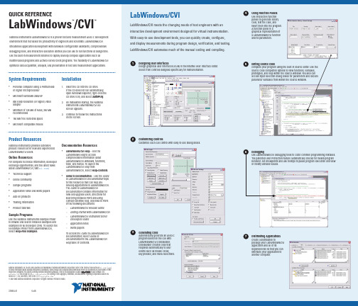
QUICK REFERENCE LabWindows/CVI™™System Requirements •Personal computer using a Pentium 600 or higher microprocessor• Microsoft Windows 2000/XP• 800 x 600 resolution (or higher) video adapter• Minimum of 128 MB of RAM, 256 MB recommended•150 MB free hard disk space •Microsoft-compatible mouse Installation1.Insert the CD into the CD drive.If the CD does not run automatically,open Windows Explorer, right-click the CD drive icon, and select AutoPlay.2. On installation startup, the NationalInstruments LabWindows/CVI 8.0screen appears.3. Continue to follow the instructionson the screen.National Instruments LabWindows/CVI is a proven test and measurement ANSI C development environment that increases the productivity of engineers and scientists. LabWindows/CVI streamlines application development with hardware configuration assistants, comprehensive debugging tools, and interactive execution utilities you can use to run functions at design time. Use the built-in measurement libraries to rapidly develop complex applications such as multithreaded programs and ActiveX server/client programs. The flexibility of LabWindows/CVI optimizes data acquisition, analysis, and presentation in test and measurement applications. LabWindows/CVILabWindows/CVI meets the changing needs of test engineers with an interactive development environment designed for virtual instrumentation. With easy-to-use development tools, you can quickly create, configure, and display measurements during program design, verification, and testing. LabWindows/CVI automates much of the manual coding and compiling.Product ResourcesNational Instruments provides extensive product resources for new and experienced LabWindows/CVI users.Online ResourcesFor complete technical information, developer exchange opportunities, and the latest news about LabWindows/CVI, visit :•Technical support•Online community•Sample programs•Application notes and white papers•Add-on products•Training information•Product tutorialsSample ProgramsUse the National Instruments Example Finder to browse and search installed examples and examples on NI Developer Zone. To launch the NI Example Finder from LabWindows/CVI, select Help»Find Examples.Documentation Resources•LabWindows/CVI Help—Use theLabWindows Help to accesscomprehensive information aboutLabWindows/CVI windows, functions,tools, and menus. To launch theLabWindows/CVI Help fromLabWindows/CVI, select Help»Contents.•Guide to Documentation—Use the Guideto LabWindows/CVI Documentation topicto find resources that can help youdevelop applications in LabWindows/CVI.The Guide to LabWindows/CVIDocumentation contains information fornew and upgrade users, directions forsearching installed PDFs and usingcontext-sensitive help, and links to PDFsof the following documents:–LabWindows/CVI Release Notes–Getting Started with LabWindows/CVI–LabWindows/CVI Instrument DriverDevelopers Guide–Application notes–White papersTo access the Guide to LabWindows/CVIDocumentation, select Guide toDocumentation in the LabWindows/CVIHelp table of contents.Designing User InterfacesDesign graphical user interfaces (GUIs) in the intuitive User Interface Editor.Select from controls designed specifically for instrumentation.1Customizing ControlsCustomize each GUI control with easy-to-use dialog boxes.2Generating CodeAutomatically generate an ANSI Cprogram based on the GUI withLabWindows/CVI CodeBuilder.CodeBuilder creates code thatresponds automatically to userevents such as mouse clicks,key presses, and menu selections.3Using Function PanelsUse interactive functionpanels to generate librarycalls, test the calls, andinsert them into the program.A function panel is agraphical representation ofa LabWindows/CVI functionand its parameters.4Editing Source CodeComplete your program using the built-in source editor. Use thesource code completion options to view functions, variables,prototypes, and help within the Source window. You also canaccess input selection dialog boxes for parameters and declareparameter variables from within the Source window.5Distributing ApplicationsCreate a distribution topackage your LabWindows/CVIapplication and all of itsdependencies so that you candistribute your application toanother computer.7DebuggingUse LabWindows/CVI debugging tools to catch common programming mistakes.The patented User Protection feature automatically checks for invalid programbehavior. Set breakpoints and use tooltips to pause program execution and viewor modify variable values.6National Instruments, NI, , and LabVIEW are trademarks of National Instruments Corporation. Refer to the Terms of Use section on /legal for more information about National Instruments trademarks. Other product and company names mentioned herein are trademarks or trade names of their respective companies. For patents covering National Instruments products, refer to the appropriate location: H H e l p»P a t e n t s in your software, the patents.txt file on your CD, or /patents. For a listing of the copyrights, conditions, and disclaimers regarding components used in USI (Xerces C++, ICU, and HDF5), refer to the USICopyrights.chm.© 2003–2005 National Instruments Corporation. All rights reserved. Printed in Ireland.373551A-01Oct05LabWindows/CVIUse built-in instrumentation libraries to interface test applications to the outside world. LabWindows/CVI includes a large set of run-time libraries for instrument control, data acquisition, analysis, and user interface creation. This chart illustrates the classes in each library. To find specific functions, press <Ctrl-Shift-P> in the Source window. You also can use the Library Tree to browse to and search for functions.L a b W i n d o w s /C V I L i b r a r y R e f e r e n c e。
再验证方案用英文
Verification Program: A comprehensive guide IntroductionIn today’s competitive digital landscape, it is essential to ensure the reliability and accuracy of software systems. Verification programs play a crucial role in validating the functionality and performance of various software applications. This document aims to provide a comprehensive guide to verification program design, emphasizing the utilization of English for better understanding and collaboration among international teams.Table of Contents1.What is Verification?2.Why is Verification Important?3.Types of Verification4.Key Components of a Verification Program–Test Planning–Test Design–Test Execution–Test Reporting5.Verification Program Workflow6.Challenges in Verification7.Best Practices for Successful Verification8.Conclusion1. What is Verification?Verification is the process of evaluating software systems to determine whether they comply with the specified requirements. It involves conducting systematic tests, inspections, and analyses to ensure that the software behaves as intended and meets the customer’s expectations.2. Why is Verification Important?Effective verification is critical to the success of software systems. It helps identify defects, ensures compliance with regulations and standards, and enhances the overall quality of the software. By thoroughly testing and validating the software, potential issues and risks can be mitigated, resulting in increased user satisfaction and reduced development costs.3. Types of VerificationThere are various types of verification techniques employed in software development. Some common types include:•Static Testing: This technique involves analyzing the software code or documentation without executing it. It includes techniques like code reviews, inspections, and walkthroughs.•Dynamic Testing: Unlike static testing, dynamic testing involves the execution of software to test its behavior. This includes techniques such as unit testing, integration testing, system testing, and acceptance testing.•Model-based Testing: This approach involves creating a model of the system and generating test scenarios based on the model.•Performance Testing: Performance testing focuses on evaluating system performance under different load conditions to identify performance bottlenecks and ensure optimal performance.4. Key Components of a Verification ProgramTest PlanningTest planning involves defining the objectives, scope, and resources required for the verification process. It includes tasks such as identifying test scenarios, creating test plans, and allocating resources.Test DesignTest design encompasses the creation of test cases and test scenarios based on the specified requirements. It involves defining inputs, expected results, and test execution steps.Test ExecutionTest execution involves running the test cases and scenarios on the software system and validating the actual results against the expected results. It includes tasks like test environment setup, test data generation, and test execution.Test ReportingTest reporting is the process of documenting and communicating the results of the verification process. It includes generating test reports, defect reports, and providing recommendations for further improvement.5. Verification Program WorkflowA typical verification program follows the following workflow:1.Define Verification Objectives: Clearly define the objectives andgoals of the verification program.2.Identify Verification Scope: Determine the scope of the verificationprogram, including the software modules and functionalities to be tested.3.Plan Verification Activities: Develop a detailed test plan, includingtest scenarios, test cases, and resource allocation.4.Execute Verification Tests: Execute the test cases and scenarios,ensuring that each step is documented and executed as planned.5.Analyze Test Results: Analyze the test results and identify anydeviations from expected outcomes.6.Report and Document: Generate test reports, defect reports, anddocumentation that summarize the results and findings.7.Perform Root Cause Analysis: Investigate the root causes of anydefects or issues encountered during the verification process.8.Iterate and Improve: Incorporate lessons learned from theverification process and implement necessary improvements for future cycles.6. Challenges in VerificationWhile verification plays a crucial role in software development, several challenges need to be addressed:•Complexity: As software systems become more complex, verification becomes more challenging, as it involves testing various functionalities andcomponents.•Time and Resource Constraints: Limited time and resources can impede the thoroughness of the verification process.•Requirement Changes: Changes in project requirements can affect the scope and planning of the verification program.•Lack of Standardization: A lack of standardized verification practices can hinder effective collaboration among international teams.7. Best Practices for Successful VerificationTo overcome the challenges and ensure successful verification, developers can follow these best practices:•Early Verification: Start the verification process as early as possible, even during the software requirements gathering phase.•Clearly Defined Requirements: Ensure that requirements are well-documented and clearly understood by all stakeholders.•Utilize Test Automation: Automation can improve the efficiency and effectiveness of the verification process.•Collaboration and Communication: Foster effective communication and collaboration among team members to exchange ideas and share insights.•Standardized Practices: Establish standardized verification practices across teams to ensure consistency and facilitate collaboration.ConclusionVerification programs are essential for the successful development and deployment of software systems. By following this comprehensive guide, software developers can design and implement effective verification programs that minimize defects, meet customer expectations, and enhance overall software quality. Emphasizing the use of English is crucial to facilitate collaboration among international teams and ensure clarity in communication.。
d-tools
d-toolsIntroductiond-tools is a versatile collection of software tools designed to simplify and streamline various tasks in the development process. With a wide range of features and capabilities, d-tools provides developers with tools that enhance productivity, increase efficiency, and improve overall software quality. This document provides an overview of the key features and benefits of using d-tools for software development projects.Features1. Integrated Development Environment (IDE)d-tools includes a powerful Integrated Development Environment (IDE) that provides a comprehensive set of features for writing, testing, and debugging code. The IDE supports multiple programming languages and offers advanced code editing capabilities such as syntax highlighting, auto-completion, and code refactoring. It also includes built-in tools for version control, project management, and collaboration, making it the go-to choice for developers seeking an all-in-one solution.2. Code Analysis and Error Checkingd-tools comes with a built-in code analysis and error checking tool that helps developers identify and fix issues in their code. The tool scans code for potential errors, securityvulnerabilities, and performance bottlenecks, providing real-time feedback and suggestions for improvement. This helps developers write cleaner, more reliable code and ensures that potential issues are caught early in the development process.3. Automated TestingTesting is a critical aspect of software development, and d-tools offers a comprehensive suite of automated testing tools. These tools allow developers to write and execute test cases, perform regression testing, and generate test reports. With d-tools’ automated testing capabilities, developers can easily catch bugs and ensure that their code functions as expected in different scenarios, ultimately leading to more robust and reliable software.4. Code DocumentationProper code documentation is vital for maintaining codebases and facilitating collaboration among developers. d-tools includes features for automatically generating documentation from code comments and annotations. This documentation can include code usage examples, API references, and explanations of implementation details. With d-tools’ code documentation capabi lities, developers can easily create comprehensive documentation that helps improve code readability and simplify future maintenance.5. Performance Profiling and Optimizationd-tools provides performance profiling and optimization tools that help developers identify and resolve performance bottlenecks in their code. These tools analyze the executiontime, memory usage, and other metrics to identify areas of code that may be causing performance issues. With d-tools’ profiling and optimization capabilities, developers can optimize their code to deliver faster and more efficient software.6. Build Automationd-tools includes a build automation tool that simplifies the process of compiling, packaging, and deploying software. Developers can define build configurations, dependencies, and custom scripts to automate the entire build process. This helps streamline the development workflow, save time, and reduce the chances of human error during the build process.7. Continuous Integration and Deploymentd-tools integrates seamlessly with popular Continuous Integration (CI) and Continuous Deployment (CD) platforms, enabling developers to automate the testing and deployment process. Developers can configure d-tools to automatically run tests, generate build artifacts, and deploy software to various environments. This automation helps ensure that software changes are thoroughly tested and deployed consistently, reducing the risk of introducing bugs into production.Benefits1. Improved ProductivityWith its comprehensive set of features and tools, d-tools helps developers become more productive. The IDE’s advanced code editing capabilities, automated testing, and buildautomation streamline repetitive tasks, allowing developers to focus on writing high-quality code. This improved productivity ultimately leads to faster development cycles and quicker time to market.2. Enhanced Code QualityBy providing code analysis and error checking, code documentation, and performance profiling tools, d-tools helps improve code quality. Developers can catch and fix issues early, resulting in cleaner and more reliable code. Additionally, the automated testing and continuous integration capabilities ensure that software changes are thoroughly tested and meet quality standards before being deployed.3. Simplified Collaborationd-tools’ built-in collaboration features, such as version control and project management tools, simplify team collaboration. Developers can work on the same codebase, track changes, and resolve conflicts seamlessly. The code documentation capabilities also facilitate knowledge sharing among team members, leading to better teamwork and improved software development processes.4. Efficient Bug Detection and ResolutionWith d-tools’ code analysis, error checking, and automated testing capabilities, bugs can be detected and fixed early in the development process. This reduces the chances of bugs reaching production and enables faster bug resolution. Improved bug detection and resolution result in more stable software and enhance customer satisfaction.5. Cost Savingsd-tools’ integrated features and automation capabilities help reduce development time and effort, resulting in cost savings. The streamlined development process, improved code quality, and efficient bug detection and resolution reduce the need for extensive manual testing, debugging, and maintenance. This leads to significant cost savings in the long run.Conclusiond-tools is a powerful collection of software tools that offers a wide range of features to simplify and enhance the software development process. With d-tools, developers can improve productivity, enhance code quality, simplify collaboration, and reduce bugs. The comprehensive set of features and benefits make d-tools a valuable asset for any development team looking to streamline their workflow and deliver high-quality software efficiently.。
vscode 中doxygen documentation generator 的使用方法
vscode 中doxygen documentationgenerator 的使用方法The topic I will be discussing is the usage of the Doxygen documentation generator in vscode.在这篇文章中,我将介绍如何在vscode中使用Doxygen文档生成器。
Doxygen is a powerful tool that automatically generates documentation from specially formatted comments in source code. It supports a wide range of programming languages, including C++, Python, and Java. Having good documentation not only benefits developers by providing clearexplanations of code functionality, but it also helps to ensure better collaboration within teams and makes iteasier for newcomers to understand and contribute to projects.Doxygen是一个强大的工具,它可以从源代码中特定格式的注释自动生成文档。
它支持多种编程语言,包括C++、Python和Java等。
良好的文档不仅有益于开发人员,提供清晰的代码功能解释,而且有助于确保团队内更好的协作,并使新手更容易理解和贡献项目。
To start using Doxygen with vscode, you need to have Doxygen installed on your system. You can easily download Doxygen from their official website and follow the installation instructions. Once installed, ensure that the Doxygen executable is added to your system's PATH environment variable so that it can be accessed from any directory.要在vscode中使用Doxygen,您需要在系统中安装Doxygen。
idea shell scripts 使用
idea shell scripts 使用Shell scripts are used to automate tasks and perform operations on a command-line interface in a Unix-like operating system. Here are some ideas on how shell scripts can be used:1. System administration: Shell scripts can be used to perform routine system administration tasks such as managing user accounts, configuring network settings, and performing backups.2. File and data manipulation: Shell scripts can be used to perform operations on files and data, such as renaming, copying, or moving files, searching and replacing text in files, and converting file formats.3. Process automation: Shell scripts can automate processes by running a series of commands or programs in a specific order. For example, a shell script can be used to automate the deployment ofa web application or to regularly run performance tests on a system.4. Task scheduling: Shell scripts can be used to schedule and automate the execution of tasks at specific times or intervals. This can be useful for performing regular maintenance tasks, generating reports, or running system checks.5. System monitoring: Shell scripts can be used to monitor system performance and collect information about hardware and software resources. They can retrieve and analyze system logs, check disk usage, monitor network connectivity, and send notifications when a certain condition is met.6. Data processing and analysis: Shell scripts can be used to process and analyze large datasets. They can extract data from files, manipulate and transform it, perform calculations, generate reports, and visualize results.7. Information retrieval and web scraping: Shell scripts can be used to retrieve information from websites and APIs using command-line tools like curl or wget. This can be useful for automating data collection, monitoring website changes, or scraping informationfor research purposes.8. Interactive command-line tools: Shell scripts can be used to create interactive command-line tools that prompt users for input, validate parameters, and perform operations based on user choices. This can be useful for creating custom command-line interfaces for specific tasks.9. Scripting for software development: Shell scripts can be used for automating repetitive tasks in software development, such as building and deploying code, running tests, managing version control systems, and generating documentation.10. System integration: Shell scripts can be used to integrate different systems and applications. They can automate the transfer of data between systems, trigger actions based on events in other systems, or extract and format data for interoperability between different platforms.These are just a few examples of how shell scripts can be used.The possibilities are endless, and their usage greatly depends on the specific needs and requirements of the user or organization.。
NS-3 Python Bindings
NS-3 Python BindingsFrom NsnamMain Page - Roadmap - Current Development - Developer FAQ - User FAQ - ToolsInstallation - Troubleshooting - HOWTOs - Samples(/wiki/index.php/Category:Samples) - Contributed Code -PapersContents1 Overview2 Build instructions3 Testing4 Running programs5 Instructions for wrapping new or changed APIs5.1 The manual way5.1.1 API of existing module changed or added5.1.2 New module5.2 The semi-automatic way5.2.1 Pitfalls5.2.1.1 "invalid use of incomplete type"5.2.1.2 KeyError5.2.1.3 RuntimeError: pygccxml error: unable to find fundamental type with name'__int128_t'.5.2.1.4 ImportError: undefined symbol6 Caveats6.1 Incomplete Coverage6.2 Conversion Constructors6.3 CommandLine6.4 Tracing6.5 Cygwin limitation7 Troubleshooting7.1 OS X problem and resolutionOverviewThe goal of Python bindings for NS-3 are two fold:1. Allow the programmer to write complete simulation scripts in Python () ;2. Prototype new models (e.g. routing protocols).For the time being, the primary focus of the bindings is the first goal, but the second goal will eventually be supported as well. Python bindings for NS-3 are being developed using a new tool called PyBindGen(/p/pybindgen) .The process by which Python bindings are handled is the following:1. Periodically a developer uses a GCC-XML (/) based API scanning script, which savesthe scanned API definition as bindings/python/ns3_module_*.py files. These files are kept under versioncontrol in the main NS-3 repository;2. Other developers clone the repository and use the already scanned API definitions;3. When configuring NS-3, pybindgen will be automatically downloaded if not already installed. Released NS-3tarballs will ship a copy of pybindgen.Build instructionsJust make sure Python development headers are installed (e.g., in debian/ubuntu: sudo apt-get install python-dev), then waf configure and waf build ns-3 as usual. If you are building a ns-3 repository version (rather than official release), you will also need the program bazaar (/) in order to automatically donwload pybindgen (e.g., in debian/ubuntu: sudo apt-get install bzr).If something goes wrong with compiling Python bindings and you just want to ignore them and move on with C++, you can disable Python with:./waf --disable-pythonTesting"./waf check" now also runs some Python unit tests, at the end.To debug the python bindings themselves, Gustavo reports this: "Unfortunately, Python does some memory allocation tricks that valgrind reports as errors. When I want to check Python bindings memory errors, I used a debug python build (configure python with ./configure --with-pydebug --without-pymalloc), and then valgrind works. But with a standard Python binary valgrind will always detect phony errors and we don't want that."Running programswaf contains some options that automatically update the python path to find the ns3 module. To run example programs, there are two ways to use waf to take care of this. One is to run a waf shell; e.g.:./waf --shellpython examples/mixed-wireless.pyand the other is to use the --pyrun option to waf:./waf --pyrun examples/mixed-wireless.pyTo run a python script under the C debugger:./waf --shellgdb --args python examples/mixed-wireless.pyInstructions for wrapping new or changed APIsThe manual wayYou will need to read some PyBindGen documentation (/PyBindGen/) .API of existing module changed or addedSo you have been changing existing NS-3 APIs and Python bindings no longer compile? Do not despair, you can manually edit the bindings API definitions to make them reflect the new changed API.The API definitions are organized as follows. For each ns-3 module <name>, the filebindings/python/ns3_module_<name>.py describes its API. Each of those files have 3 toplevel functions:1. def register_types(module): this function takes care of registering new types (e.g. C++ classes, enums) that aredefined in tha module;2. def register_methods(module): this function calls, for each class <name>, another functionregister_methods_Ns3<name>(module). These latter functions add method definitions for each class;3. def register_functions(module): this function registers ns-3 functions that belong to that module.New moduleIf you are adding a new module, Python bindings will continue to compile but will not cover the new module. To cover a new module, you have to create a bindings/python/ns3_module_<name>.py file, similar to the what is described in the previous section, and register it in the variable LOCAL_MODULES inbindings/python/ns3modulegen.pyThe semi-automatic wayIt is possible to use GCC-XML and PyGccXml to scan API definitions automatically. The API scanner is not perfect, but it gets most of the job done.First you need to install the necessary tools:1. Get CMake (can either build from source or download binaries for windows, linux i386);2. Get GCC-XML (must download from CVS). Instructions are to be found here(/HTML/Download.html) . Note that, as with all CVS versions, stability may vary.This CVS snapshot is known to work: cvs up -D "2009-09-21".3. Download and install pygccxml (/pygccxml/download.html) , version 1.0.0;(To install: python setup.py install);4. Run ./waf configure, to let ns-3 detect the python scanning tools. You should see something along theselines; if not, something is wrong:[...]Checking for Python module pygccxml : okChecking for pygccxml version : ok 1.0.0Checking for program gccxml : ok /usr/local/bin/gccxml Checking for gccxml version : ok 0.9.0[...]Python Bindings : enabledPython API Scanning Support : enabledNow you are ready to scan; run ./waf --python-scan. If all goes well, the files in bindings/python/* should have been updated with new API definitions. Now you can build ns-3 as usual, and new Python bindings are compiled. Pitfalls"invalid use of incomplete type"If you get a "invalid use of incomplete type" compilation error message, like this:[722/796] cxx: build/debug/bindings/python/ns3_module_internet_ -> build/debug/bindings/python/ns3_ debug/ns3/ptr.h: In destructor ‘ns3::Ptr<T>::~Ptr() [with T = ns3::Ipv4Interface]’:debug/ns3/arp-cache.h:50: instantiated from heredebug/ns3/ptr.h:439: error: invalid use of incomplete type ‘struct ns3::Ipv4Interface’debug/ns3/arp-cache.h:40: error: forward declaration of ‘struct ns3::Ipv4Interface’It means that PyBindGen is generating code that makes use of the implicit copy constructor, and the copy constructor does not work with incomplete types. The solution is to make the copy constructor private, then rescan the API.class ArpCache : public Object{private:ArpCache (ArpCache const &);ArpCache& operator= (ArpCache const &);[...]}KeyErrorIf you get a KeyError during bindings code generation, like:File "/home/gjc/projects/ns/ns-3-allinone/ns-3-distributed/bindings/python/apidefs/gcc-LP64/ns3_module_m module.add_class('DistributedSimulatorImpl', parent=root_module['ns3::SimulatorImpl'])KeyError: 'ns3::SimulatorImpl'It is possible that the order of registering module types is incorrect. You should correct the inter-module dependencies in the module's wscript file:- sim = bld.create_ns3_module('mpi', ['core'])+ sim = bld.create_ns3_module('mpi', ['core', 'simulator'])Then re-scan the python bingins (waf --python-rescan).RuntimeError: pygccxml error: unable to find fundamental type with name '__int128_t'.Recent optimizations in the Time class make use of a __int128_t type, which pygccxml is not written to recognize. A simple workaround for this problem is to configure with --high-precision-as-double, scan, then switch back to normal options:./waf configure --high-precision-as-double./waf --python-scan./waf configure [normal options]Alternatively, update pygccxml to svn revision 1844 (/viewvc/pygccxml? revision=1844&view=revision) .ImportError: undefined symbolIf you declare but don't implement a public method, and rescan the bindings, compilation may succeed but you may get a cryptic runtime error such as:./waf --pyrun examples/tutorial/first.pyImportError: /home/user/ns-3-allinone/ns-3-dev/build/debug/bindings/python/ns3/_ns3.so: undefined symbol Command ['/usr/bin/python', 'examples/tutorial/first.py'] exited with code 1This can be fixed by finding the method that exists in the class declaration but that is not implemented, and removing the declaration, and rescanning the bindings.CaveatsPython bindings for NS-3 is a work in progress, and some limitations are know by developers. Some of these limitations (not all) are listed here.Incomplete CoverageFirst of all keep in mind that not 100% of the API is supported in Python. Some of the reasons are:1. some of the APIs involve pointers, which require knowledge of what kind of memory passing semantics (whoowns what memory). Such knowledge is not part of the function signatures, and is either documented orsometimes not even documented. Annotations are needed to bind those functions;2. Sometimes a unusual fundamental data type or C++ construct is used which is not yet supported byPyBindGen;3. GCC-XML does not report template based classes unless they are instantiated.Most of the missing APIs can be wrapped, given enough time, patience, and expertise, and will likely be wrapped ifbug reports are submitted. However, don't file a bug report saying "bindings are incomplete", because we do not have manpower to complete 100% of the bindings.Conversion ConstructorsConversion constructors(/infocenter/compbgpl/v9v111/topic/com.ibm.xlcpp9.bg.doc/language_ref/cplr384.htm) are not fully supported yet by PyBindGen, and they always act as explicit constructors when translating an API into Python. For example, in C++ you can do this:Ipv4AddressHelper ipAddrs;ipAddrs.SetBase ("192.168.0.0", "255.255.255.0");ipAddrs.Assign (backboneDevices);In Python, for the time being you have to do:ipAddrs = ns3.Ipv4AddressHelper()ipAddrs.SetBase(ns3.Ipv4Address("192.168.0.0"), ns3.Ipv4Mask("255.255.255.0"))ipAddrs.Assign(backboneDevices)CommandLineCommandLine::AddValue works differently in Python than it does in NS-3. In Python, the first parameter is a string that represents the command-line option name. When the option is set, an attribute with the same name as the option name is set on the CommandLine object. Example:NUM_NODES_SIDE_DEFAULT = 3cmd = mandLine()cmd.NumNodesSide = Nonecmd.AddValue("NumNodesSide", "Grid side number of nodes (total number of nodes will be this number squa cmd.Parse(argv)[...]if cmd.NumNodesSide is None:num_nodes_side = NUM_NODES_SIDE_DEFAULTelse:num_nodes_side = int(cmd.NumNodesSide)TracingCallback based tracing is not yet properly supported for Python, as new NS-3 API needs to be provided for this to be supported. Bug #127 (/bugzilla/show_bug.cgi?id=127) for details.Pcap file writing is supported via the normal API.Ascii tracing is supported since NS-3.4 via the normal C++ API translated to Python. However, ascii tracing requires the creation of an ostream object to pass into the ascii tracing methods. In Python, the C++ std::ofstream has beenminimally wrapped to allow this. For example:ascii = ns3.ofstream("wifi-ap.tr") # create the filens3.YansWifiPhyHelper.EnableAsciiAll(ascii)ns3.Simulator.Run()ns3.Simulator.Destroy()ascii.close() # close the fileThere is one caveat: you must not allow the file object to be garbage collected while NS-3 is still using it. That means that the 'ascii' variable above must not be allowed to go out of scope or else the program will crash.Cygwin limitationPython bindings do not work on Cygwin. This is due to a gccxml bug: /Bug/view.php?id=7572You might get away with it by re-scanning API definitions from within the cygwin environment (./waf --python-scan). However the most likely solution will probably have to be that we disable python bindings in CygWin.If you really care about Python bindings on Windows, try building with mingw and native python instead. Or else, to build without python bindings, disable python bindings in the configuration stage:./waf configure --disable-pythonTroubleshootingOS X problem and resolutionProblem: I installed pygccxml 1.0.0 and pybindgen 0.14.0, patched bindings/python/wscript to use the newer versions, installed gccxml-devel from ports, and succesfully compiled ns-3. All tests (./test.py) work fine. However, when I try to run a python-example I get a python crash:$ ./waf --pyrun examples/wireless/mixed-wireless.pyWaf: Entering directory `/Volumes/Shared/Projects/ns-3/ns-3-dev/build'Waf: Leaving directory `/Volumes/Shared/Projects/ns-3/ns-3-dev/build''build' finished successfully (1.114s)Fatal Python error: Interpreter not initialized (version mismatch?)Command ['/usr/bin/python', 'examples/wireless/mixed-wireless.py'] exited with code -6Solution: This can be due to the version used to build ns3 is not the same as the interpreter, possibly due to multiple versions of Python on the system. However, it was resolved for this specific OS X case as follows:"We found the problem, it was in Mac OS X "port" system, causing confusion with ns-3 configure script. Adding a symlink /opt/local/bin/python -> /opt/local/bin/python2.6 fixed the issue."Retrieved from "/wiki/index.php/NS-3_Python_Bindings"This page was last modified on 22 December 2010, at 00:42.。
- 1、下载文档前请自行甄别文档内容的完整性,平台不提供额外的编辑、内容补充、找答案等附加服务。
- 2、"仅部分预览"的文档,不可在线预览部分如存在完整性等问题,可反馈申请退款(可完整预览的文档不适用该条件!)。
- 3、如文档侵犯您的权益,请联系客服反馈,我们会尽快为您处理(人工客服工作时间:9:00-18:30)。
Generating Code and Documentation from Lightweight Abstract GrammarsRadu GrigoreUniversity College DublinAbstract.Abstract grammars are used in papers when toy languagesare described.For the development of language processing tools it is alsouseful to have a short and explicit description of the abstract grammarof the language being processed.This paper presents a little language forexpressing lightweight abstract grammars,a little language for writingtemplates that refer to the information in the abstract grammar,andthe tool to process these.The tool generates,for example,code for theAbstract Syntax Tree(AST)data structures,a table view and a graphicalview of the abstract grammar.1Introduction and Related WorkRepetition is a sign that the task is better suited for a tool than a human.If the task is not completely repetitive the tool needs guidance,and one common way to give it is by writing a program in a little language[1,2]that the tool understands. The architecture of tools that process languages(such as compilers,interpreters, and translators)is fairly standard.The pipeline begins with a parser that builds an AST,which is then transformed and evaluated in stages until the output is produced.Because the architecture is standard,writing a language processing tool feels somewhat repetitive and,indeed,there are tools that help.Commonly used compiler compilers in the Java world include Antlr[3], JavaCC[4],and SableCC[5].They provide significant help for the early pipeline stages.The JastAdd system[6]aims to aid the construction of the whole pipeline and generates common stages such as symbol resolution and typechecking.In Antlr the user writes a grammar that defines the concrete syntax.Antlr generates a parser from the grammar and from built-in code templates,the latter of which contain library calls to the Antlr API.Optionally,Antlr generates AST data structures,also from the grammar and other built-in code templates that refer to the Antlr API.The grammar can be annotated to say which information should end up in the AST and which not(for example,semicolons at the end of statements don’t need afield in the AST).Idea:The programmer can describe a separate abstract grammar and write templates.It is easier to work with an abstract grammar when it is described in a simple language and decoupled from the concrete grammar.Since the pro-grammer writes templates,the generated code is easy to integrate with the rest of the system.Moreover,templates for generating documentation can be writtentoo.This combination proved successful in the development of the frontend of FreeBoogie[7],which will be a backend for software verifiers.2A Small ExampleWe want to write a tool that uses Bentley’s survey language[1],say,to administer questionnaires interactively.Here is an example of the input we want to be able to process.Q What is your political party?1Democrat2Republican3*OtherThefirst thing we do is to describe the abstract grammar.Questionnaire=Item!item,Questionnaire tail;Item=String!question,Boolean!custom,Choices choices;Choices=String!choice,Choices tail;The second thing we do is to write down a template.\normal_classes{\file{\ClassName.java}public class\ClassName{...public\ClassName(\members[,]{\MemberType\memberName}){\members{\if_nonnull{assert\memberName!=null;}{}this.\memberName=\memberName;}}...}}One of the generatedfiles is Item.java.public class Item{...public Item(String question,Boolean custom,Choices choices){assert question!=null;this.question=question;assert custom!=null;this.custom=custom;this.choices=choices;}...}We can customize the template to generate a HTML description of the abstract grammar,a T E Xfile,a dotfile to visualize the AST,a Makefile,and so on.3The Abstract GrammarThe abstract grammar is a list of rules,of three possible types(inheritance, composition,and specification):Class1:>Class2,Class3;Class2=Type1name1,Type2name2;Class:arbitrary specification text on one lineAn identifier denotes a class if it appears on the left side of a rule.A class is normal if it appears on the left side of a composition rule;otherwise it is abstract.Types are arbitrary identifiers(including those that denote classes)or enumerations:2enum(EnumTypeName:VALUE1,VALUE2,VALUE3)The type can be followed by the‘!’sign,meaning that the current member is nonnull.A member is a child if its type is a class;otherwise it is a primitive.Specification rules are used,for example,if one wants to specify class invariantsto be checked later with a tool such as ESC/Java[8,9].To summarize the information that goes into an abstract grammar we canuse an abstract grammar.AbstractClass=String!name;NormalClass=String!name,String!base,Members members,Enums enums,Invariants invs;Members=String!type,String!name,boolean isPrimitive,boolean nonNull,Members tail;Enums=String!name,EnumValues values,Enums tail;EnumValues=String!name,EnumValues tail;Invariants=String!inv,Invariants tail;4The TemplatesTemplates are arbitrary textfiles that contain macros,similar in form to T E X macros[10].There are four types of macros:–macros for directing the output of the template processor(\file)–list macros(\classes,\members,\enums,\values,\invariants)–data macros(\class name,\base name,\member type,\member name,\enum name, \value name,\inv text)–test macros(\if abstract,\if primitive,\if nonnull,\if enum)–helper macros(\abstract classes,\normal classes,\children,\primitives) The\file{name}can appear anywhere and it instructs the template pro-cessor to send the following characters to thefile name.By default the outputgoes to/dev/null,which allows one to easily add comments at the beginningof a template.The list macros take two parameters,thefirst of which is optional and de-faults to the empty string:\macro[sep]{text}.The text is processed multipletimes setting the current class(or member,or enumeration,or value,or invari-ant)to all values appearing in the abstract grammar.The current class,the current member,the current enumeration,the current value,and the current invariant for the current environment.The data macros expand to the current class(or member name,or member type,etc.).Hence,they must be enclosed by the proper list macro.(It is safeto nest list macros of the same kind but only the current value correspondingof the innermost list can be accessed.)All data macros,except for\inv text,come in fourflavors,corresponding to different case conventions for the output(for example,\class name,\ClassName,\className,and\CLASS NAME).The test macros receive two parameters,as in\if abstract{yes}{no},and select one of two pieces of the template to process based on the current environ-ment.Helper macros are defined in terms of others.For example,\children[sep]{text}is the same as\members[sep]{\if primitive{}{text}}.These are currently built-in,but it is probably a good idea to allow the user to define such aliases.35Conclusion and Future WorkAn explicit abstract grammar representation is helpful in presenting a language, can be used as a basis for code and documentation generation,and makes main-tenance easier.In general,it is a good idea to use such an approach when the abstract grammar is evolving,has medium or large size,and when documenta-tion must be generated alongside the code.One possible evolution is to support lists in the abstract grammar explicitly. Then the templates can map them to a collection data structure.(Note that Java collections are mutable.)Another possible evolution is to allow users to define macro aliases.This would reduce repetition in the templates. Acknowledgments.This work is funded by the Information Society Technolo-gies program of the European Commission,Future and Emerging Technologies under the IST-2005-015905MOBIUS project.The article contains only the au-thor’s views and the Community is not liable for any use that may be made of the information therein.The author would like to thank Joseph Kiniry,Mikol´aˇs Janota,and Fintan Fairmichael for advice on how to improve the presentation.References1.Bentley,J.:Little munications of the ACM29(8)(1986)711–7212.Mernik,M.,Heering,J.,Sloane,A.M.:When and how to develop domain-specificlanguages.ACM Computing Surveys37(4)(December2005)316–3443.Parr,T.:The ANTLR system homepage./4.Sun Microsystems:The JavaCC homepage.https:///5.Gagnon,E.M.,Hendrie,L.J.:The SableCC homepage./6.Hedin,G.,Magnusson,E.:JastAdd—an aspect-oriented compiler constructionsystem.Science of Computer Programming47(1)(2003)37–587.Grigore,R.:The FreeBoogie SVN repository.https://mobius.ucd.ie/browser/src/freeboogie/trunk/FreeBoogie8.Cok,D.,Kiniry,J.:ESC/Java2:Uniting ESC/Java and JML.Construction andAnalysis of Safe,Secure and Interoperable Smart devices3362(2005)108–128 9.Flanagan,C.,Leino,K.R.M.,Lillibridge,M.,Nelson,G.,Saxe,J.,Stata,R.:Ex-tended static checking for Java.ACM SIGPLAN Notices37(5)(2002)234–245 10.Knuth,D.E.:The T E Xbook.Addison–Wesley(1986)4Appendix for Evaluation Only:DemonstrationThe demo will consist of a short introduction using slides followed by an interac-tive showcase of the tool.If desired,copies of the tool and the datafiles used can be provided in advance so that participants can replicate the steps themselves during the demo.IntroductionThe demonstration will begin with the slides attached to the end of this doc-ument.The purpose is to present the main definitions and to emphasize the design decisions with the aid of an example.For example,I will say that from the point of view of the design it is much more important what types of macros are available than what exactly are the macros in each category.Also,the hier-archical structure of the abstract grammar leads to the natural rules for nesting macros.Finally,the selection of helper macros is rather arbitrary—they were added as needed.In fact,I am considering adding a mechanism that allows the user to add such extra helpers and I will definitely pass the‘considering’stage if I shall need more than four.This illustrates the“keep it simple”principle of design.Another result of this principle is that the abstract grammar cannot explicitly express lists.That is because I prefer using functional data structures for the AST.The AST is usually huge and mutating things gets one in trouble in no-time.Of course,adding explicit support for lists is possible and,in fact,a previous implementation had such support.This should give you aflavor of the kind of things I will talk about while presenting the slides.(Please note that the slides are only afirst draft.)FreeBoogie as a Case StudyDuring this portion of the demo the projector will show whatever appears on the screen of my laptop.The plan is tofirst go through the FreeBoogie abstract grammar,then through the templates,andfinally show how to perform a mod-ification in the abstract grammar.Thefirst two steps will showcase what kind of documents can be generated,and the last step will show how the use of this tool eases maintenance.To familiarize the audience with the little language BoogiePL I will show a BoogiePL program.Then I will briefly explain the main features of the language while showing its abstract grammar,which takes about70lines with comments. This will illustrate how the explicit representation of the abstract grammar fa-cilitates communication.//This is the abstract grammar for FreeBoogie used to generate//the AST.See also the template(*.tpl)files.//The program is a(functional)list of(global)declarationsDeclaration:>TypeDecl,ConstDecl,Function,Axiom,VariableDecl,Procedure,Implementation;1TypeDecl=String!name,Declaration tail;ConstDecl=String!id,Type!type,Declaration tail;Function=Signature!sig,Declaration tail;Axiom=Expr!expr,Declaration tail;VariableDecl=String name,Type!type,Declaration tail;Procedure=Signature!sig,Specification spec,Declaration tail; Implementation=Signature!sig,Body!body,Declaration tail;//Types and constantsType:>PrimitiveType,UserType,ArrayType,GenericType,DepType,TupleType;ArrayType=Type!rowType,Type colType,Type!elemType; PrimitiveType=enum(Ptype:BOOL,INT,REF,NAME,ANY,ERROR)ptype; GenericType=Type!param,Type!type;DepType=Type!type,Expr!pred;UserType=String!name;TupleType=Type!type,TupleType tail;//Signatures are used to represent uninterpreted functionsSignature=String!name,Declaration args,Declaration results;//Procedures and implementationsSpecification=enum(SpecType:REQUIRES,MODIFIES,ENSURES)type,Expr!expr,boolean free,Specification tail;Body=Declaration vars,Block blocks;Block=String!name,Commands cmds,Identifiers succ,Block tail;//succ==null means that we return//CommandsCommands=Command!cmd,Commands tail;Command:>AssignmentCmd,AssertAssumeCmd,HavocCmd,CallCmd; AssignmentCmd=Expr!lhs,Expr!rhs;AssertAssumeCmd=enum(CmdType:ASSERT,ASSUME)type,Expr!expr; HavocCmd=AtomId!id;CallCmd=String!procedure,Identifiers results,Exprs args;//ExpressionsExpr:>BinaryOp,UnaryOp,Atom,Exprs;BinaryOp=enum(Op:PLUS,MINUS,MUL,DIV,MOD,EQ,NEQ,LT,LE,GE,GT,SUBTYPE,EQUIV,IMPLIES,AND,OR)op, Expr!left,Expr!right;UnaryOp=enum(Op:MINUS,NOT)op,Expr!e;Atom:>AtomLit,AtomNum,AtomId,AtomFun,AtomOld,AtomCast,AtomQuant,AtomIdx;AtomLit=enum(AtomType:FALSE,TRUE,NULL)val;AtomNum=BigInteger val;AtomId=String!id;AtomFun=String!function,Exprs args;AtomOld=Expr!e;AtomCast=Expr!e,Type!type;AtomQuant=enum(QuantType:EXISTS,FORALL)quant,Declaration!vars, Trigger trig,Expr!e;AtomIdx=Atom!atom,Index!idx;Index=Expr!a,Expr b;//Some simple listsTrigger=String label,Exprs!exprs,Trigger tail;Identifiers=AtomId!id,Identifiers tail;Exprs=Expr!expr,Exprs tail;//Some class invariantsSpecification:type==Type.MODIFIES==>\typeof(expr)==AtomId2In FreeBoogie,templates are used to generate:–documentation–AST data structures(Java)–the Visitor base classes(Java)–some help for the build systemThe documentation template is presentedfirst.It generates a HTML page with a table view and a graphic view of the abstract grammar that should re-inforce the audience’s grasp of BoogiePL.The AST data structures are rather simple;we shall observe how the Visitor pattern is supported.Next we move on to the Visitor pattern.Two base classes,Evaluator and Transformer,are gen-erated automatically.The implementation is a variation of the standard Visitor pattern that makes it easy to deal with the immutable nature of the AST data structures.(For example,path copying is done in the class Transformer and the writer of concrete visitors doesn’t need to worry about it.)Related to visitors, we shall see how some boilerplate code is generated that helps implement new visitors.Finally,a list of the generatedfiles is created,so that the build script need not be changed when the abstract grammar is modified.The last part involves modifying the program and show what this entails.One possibility is to show how we can eliminate the TupleType from the grammar. Of course,its function should be delegated somehow and at least the typechecker needs to be updated.We’ll see,however,that the modifications are much less repetitive and error prone than they would be without the use of this tool.I will also try to cover some things that were mentioned only in passing in the paper or not at all(such as how the inheritance rules work,how to integrate with a parser generator,and more related work,even unpublished).3。