
东芝2000系列维修手册
东芝2000系列维修手册1:误码表(清除/停止+8)复印机纸路夹纸 E01 供纸部夹纸 E11 E17 供纸单元传送路经中夹纸 E2 E02 E12 E19E03 E13E04 E14E05 E15E08 E16A D F传纸路经中夹纸 E71 分页器中夹纸 E81 E85E72 E82 E88E73 E83E75 E84驱动系统请求检修 C01 复印机主电机工作异常C04 PFP(纸盒工作台)主电机工作异常C05 ADU(双面器)主电机工作异常供纸系统请求检修 C11 ADU侧的电机工作异常C12 ADU末端电机工作异常C13 上供纸盒工作异常C14 下供纸盒工作异常C15 PFP上供纸盒工作异常C16 PFP中供纸盒工作异常C17 PFP下供纸盒工作异常C18 LCF(大容量纸库)供纸盒工作异常光学系统请求检修 C21 拖架初始化错误C22 透镜初始化错误C23 反光镜初始化错误C26 曝光灯丝容断处理系统请求检修 C33 无法简易设定C35 转印/分离相接处留有显影剂定影器单元 C41 开机时热敏电阻异常或加热器断路C43 预热期间或复印机已就绪时热敏电阻异常C44 预热期间或复印机已就绪时加热器断路C45 副加热器开路通讯系统请求检修 C54 分页器与主CPU通讯异常C55 ADF与主CPU通讯异常C56 PFC与主CPU通讯异常ADF请求检修 C72 定位传感器调整失灵C73 EEROM初始化错误C74 排出/保留传感器调整失灵分页器请求检修 C81 走纸电机异常C82 格升降电机异常C83 上限位错误C84 下限位错误C85 初始位置传感器异常C86 装订导条驱动电机异常C87 装订驱动电机异常C88 复印件移动传感器出错其它请求检修 C93 接收不到ADF原稿停止信号2:复印机输出信号检查(03/04)01 主电机ON 11 主电机OFF02 供纸辊离合器ON 12 供纸辊离合器OFF03 定位辊离合器ON 13 定位辊离合器OFF06 墨粉电机ON 16 墨粉电机O07 光风扇ON 17 光风08 出纸风扇/ 底部风扇ON 18 出纸风扇/ 底部风扇OFF10 总计数器20 扫描电机21 透镜电机22 反光镜电机24 原稿电机30 充电输出31 转印输出32 分离输出33 曝光灯34 预转印偏压40 复印机上供纸托盘电机41 复印机上纸盒供纸辊离合器42 复印机传输离合器43 复印机下供纸托盘电机44 复印机下纸盒供纸辊离合器45 ADU制动端电机46 ADU恻面端电机47 ADU供纸辊离合器48 ADU堆纸离合器49 PFP上供纸托盘电机50 PFP上纸盒供纸辊离合器51 PFP传输离合器52 PFP中供纸托盘电机53 PFP中纸盒供纸辊离合器54 PFP下供纸托盘电机55 PFP下纸盒供纸辊离合器56 手动供纸辊离合器57 LCF托盘电机58 LCF供纸电机60 ADU电机61 PFP主电机80 DF独立老化(单面操做)81 DF独立老化(双面操做)82 DF搓纸辊转动83 DF定位辊转动84 DF传送带转动85 DF传送带转动90 分页器传送电机ON91 分页器格升降电机ON92 分页器无纸养护3:复印机调整方试(05)代码名称允许输入值初始值00 自动墨粉传感器 -------- ----01 手动曝光(100%) 0-255 128 值越大,图像02 手动曝光(154%) 0-255 12803 手动曝光(50%) 0-255 12804 手动曝光(200%) 0-255 12805 自动曝光(100%) 0-255 12806 自动曝光(154%) 0-255 12807 自动曝光(50%) 0-255 12808 自动曝光(200%) 0-255 12809 允许曝光范围(亮) 0-255 50 值越大,亮度10 允许曝光范围(暗) 0-255 210 值越大,亮度越14 照片曝光(100%) 0-255 157 值越大,图像越15 照片曝光(154%) 0-255 12816 照片曝光(50%) 0-255 12817 照片曝光(200%) 0-255 12821 扫描电机速度调整 0-15 8 值加1速度25 LED消去阵列定时调整(100%) 0-15 8 值加1后移0。
5MM26 LED消去阵列定时调整(200%) 0-15 827 LED消去阵列定时调整(50%) 0-15 830 LED消去阵列定时调整(先端) 0-15 831 LED消去阵列定时调整(后端) 0-15 835 先端空白调整 0-15 036 后端空白调整 0-15 038 栅偏压输出 0-255 128 值越大39 转印变压器输出 0-255 12840 分离变压器输出 0-255 12842 栅偏压输出(照片方式) 0-255 13843 显影偏压调整 0-255 10049 自动曝光自动调整 ------- -----53 配准(100%,下进纸) 0-40 20 值加1前端移0。
854 配准(200%,下进纸) 0-15 855 配准(50%,下进纸) 0-15 856 配准(100%,S F B ) 0-15 858 配准(100%,ADU进纸) 0-15 860 透镜位置调整(100%) 0-40 20 值增加1透镜放大移61 反光镜位置调整(100%) 0-40 2062 透镜位置调整(200%) 0-40 2063 反光镜位置调整(200%) 0-40 2064 透镜位置调整(50%) 0-40 2065 反光镜位置调整(50%) 0-40 2080 定位量(长下进纸) 0-31 20 值增加1纸更弯曲81 定位量(手动) 0-31 2482 定位量(长上进纸) 0-31 2083 定位量(长ADU进纸) 0-31 2084 ADF定位量(第1页) 0-15 8 值增加185 ADF定位量(第2页) 0-15 887 ADF定位量(2和1原稿间隙) 0-15 8 值增加1原稿间隙90 自动墨粉传感器调整值班室 0-255 12892 定位量(PFP) 0-31 20 值增加1纸93 定位量(LCF) 0-31 2094 定位量(短下进纸) 0-31 1695 定位量(短上进纸) 0-31 1696 定位量(短ADU进纸) 0-31 1697 ADF EEPROM初始化 -------- ------4:设定方式(0+8)代码名称允许输入值初始值备注03 信息语言 0-2 0 ----04 自动分页方式 0-3 0 原稿放入ADF后将不用 1:装订 2:分页 3:分组05 自动两面复印方式 0-3 1 原稿放入ADF后,复式 0:不用 1:单面到两面2:两面到两面 3:两面到单面或两面到两面07 处理控制方式 0-1 0 0:不用 1:08 版本 0-3 0-3 0:欧洲2:日本 3:其它09 实际尺寸复制比例 0-1 0-1 0:100% 1:101%10 定时器方式 0-10 3 0:不用2:30秒 3:45秒4:60秒 N:N。
1511 自动电源保存 0-15 11 0:不用 1:30秒150秒钟 7:4分钟8:5分钟 9:7分钟10:10分钟 11:15分钟12:20分钟 13:30分钟14:45分钟 15:60分钟12 最大复印数 0-3 0 0:最大999 2:最大9 3:最大60013 进纸再试 0-1 0 0:进纸再试1:非进纸再试方式14 进纸盒优先选择 0-6 0 0:A4/LT2:上进纸器 3:下进纸器4:PFR上进纸盒5:PFP中进纸盒6:PFP下进纸盒15 曝光优先选择 0-2 0 0:自动 1:16 A3/LD双计数 0-1 0 0:单计数17 手动进纸自动开始 0-1 0 0:由PRINT键开始1:自动开始18 ADF方式优先选择 0-1 0 0:ADF方式19 分页器方式优先选择 0-3 0 0:不分页 1 2:分页 3:分组20 消边优先选择 0-2 2 0:不消边2:自动消边21 供纸盒自动变换 0-1 1 0:不用22 APS方式优先选择 0-2 0 0:手动 1:APS23 原稿位置测定 0-1 0 0:自动25 导向偏压控制选择 0-1 0 0:采用导向偏压控制1:取消导向偏压(常关)27 ADF的APS方式 0-2 0 0:检测每页原稿PRINT键后的响应 1:只检测首页原稿2:不复印空白原稿28 挂上APS/AMS后按 0-2 0 0:响应(开始复印1:第1次按不响应2:不复印31 复印纸尺寸(LCF) 0-14 3,4 3:LT35 供纸盒/ADU连接 0-3 0 0:自动检测2:ADU 3:不连接36 PFP连接 0-4 0 0:自动检2:2号供纸盒 3:3号供纸盒4:不连接37 分页键选择顺序 0-1 0 0:分页---装订--分1:装订---分页--分组---不分页38 加热辊温度设定值(节能) 0-11 5 0:关 1:110度 2:120 3:130度 4:140度5:150度 6:160度7:170度 8:180度9:190度 10:200度11:210度43 可重设计数器显示 0-3 0 0:不44 用 1:可重设计数原始计数器显示 2:原始计数器显示 3:44 复印后全清除 0-1 0 0:不用47 预运行时间设定值 0-18 3 0:关 1:5秒3:15秒 4:20秒 5:25秒6:30秒 7:40秒 8:50秒9:60秒 10:70秒 11:80秒12:90秒 13:100秒14:110秒 15:120秒16:130秒 17:140秒18:150秒48 LED消去阵列消除区域宽度 0-1 0 0:宽(51,54,58%)51 UA方式选择 0-1 0 0:不用用52 快速复印方式 0-1 0-1 0:不用53 曝光过度检测 0-2 0 0:保持 1:自2:不用54 硬币控制功能 0-2 0 0:不用 1:采56 自动关闭 0-20 6 下列时间自动关0=3 1=5 2=10 3=154=20 5=25 6=30 7=408=50 9=60 10=70 11=8012=90 13=100 14=110 15=12016=150 17=180 18=21019=240 20=不用62 AMS复印停止开关 0-1 1 0:不停止68 COPYYLYZER 0-1 0 0:不用69 PM计数器设定值 0-999999 000000 0:不用PM计数器,非0:当设定值76 运行计时器(鼓) 0-277小时 0 读数为时,分,秒77 运行计时器(显影剂) 0-277小时 0 读数为时,分,秒79 当前PM计数器值室 0-999999 000000 当前复印量80 电话号码 14位 0 输入14位电话号码81 前盖打开计数器 0-999999 000000 --------89 加热器异常计数器 0-9 0 0-1:可复印 2以上:不可以99 出错记录 ---- ---- 显示最近几年8个出错代100 锁定计数器 0-1 0 0:不锁101 通电时间计数器 0-99999小时 0 读数为时,分,秒102 复印时间计数器 0-99999小时 0 读数为时,分,秒104 预运行设定值(厚纸方式) 0-6 2 0:3秒 1:5秒 2:10秒25秒105 APS传感器位置 1-2 2 1:LT系列106 原稿放置方式(ADF) 0-1 0 0:直接停止报 1:切换返108 LED消去阵列(用于边缘消除) 0-1 0 0:窄敞109 通用复印纸 0-14 ---- FOLIO(欧洲) COMP(美110 尺寸(0:非标) 140-297/210-432 297/420 宽/长欧洲/长美国111 尺寸(1:A5-R) 140-297/210-432 148/210 宽/长112 尺寸(2:B5) 140-297/210-432 257/182 宽/长113 尺寸(3:B5-R) 140-297/210-432 182/257 宽/长114 尺寸(4:A4) 140-297/210-432 297/210 宽/长115 尺寸(5:A4-R) 140-297/210-432 210/297 宽/长116 尺寸(6:FOLIO) 140-297/210-432 210/330 宽/长117 尺寸(7:B4) 140-297/210-432 257/364 宽/长118 尺寸(8:A3) 140-297/210-432 297/420 宽/长119 尺寸(9:ST-R) 140-297/210-432 140/216 宽/长120 尺寸(10:LT) 140-297/210-432 280/216 宽/长121 尺寸(11:LT-R) 140-297/210-432 216/280 宽/长122 尺寸(12:LG) 140-297/210-432 216/356 宽/长123 尺寸(13:COMP) 140-297/210-432 258/356 宽/长124 尺寸(14:LD) 140-297/210-432 280/432 宽/长。
东芝笔记本电脑维修手册 Tecra_A1_Series
FIELD REPLACEABLE UNIT DOCUMENTATIONTecra TMnot connected to the unit and the environment in which you are working on is protected fromElectro-Static Discharge(ESD).A1 SeriesBATTERY PACK REMOVAL1. Turn the computer upside down as shown.2. Slide the battery release lever in the direction of the arrow.3. Lift out the battery pack assy .HDD REMOVAL1. Turn the computer upside down.2. Remove two M2.5x16 black flat head screws securing HDD slot cover and pull out the cover ..4. Separate the battery pack from the battery cover.OPTIONAL PC CARD REMOVAL 1. Press the eject button of the PC Card you want to remove.2. Press the extended eject button to pop the PC card out slightly.3. Grasp the PC Card and pull it outNOTE: Before removing any PCMCIA device, make sure it is “STOPPED” in the PC Card Manager.Battery packBattery cover A1 Series6. Remove four M3x4 brass flat head screws securing the HDD bracket to the drive.4. Slowly spread out the memory clips and pull the memory module out of the connector on a 45 degree angle.3. Remove one M2.5x5 black flat head screw securing the HDD assembly.4. Grasp the HDD bracket handle and pull to disconnect the HDD assembly.5. Lift the HDD assembly out of the HDD bay.MEMORY MODULE REMOVAL1. Turn the computer upside down.2. Remove one M2.5x4 black flat head screwsecuring the memory cover.3. Lift out thecover .M2.5x5 black flat head screwHDD assyHDD bracket handleM3x4 brass flat head screwsM2.5x4 black flat head screwMemory moduleMemory clipsA1 SeriesWIRELESS LAN CARD REMOVAL1. Turn the computer upside down.2. Remove one M2.5x4 black flat head screw securing the Mini PCI slot cover.3. Lift out the PCI slot cover .4. Peel off the glass tape securing the mini coax cables.5. Disconnect the white mini coax cable from main connector and the black mini coax cable from aux connector.6. Gently press out the Mini PCI slot clips and pull the Mini PCI card out of the connector on a 30 degree angle.MODEM BOARD REMOVAL1. Remove one M2.5x4 black flat head screw securing the modem slot cover.2. Insert your finger nail or the case separator into the notched side of the cover and lift up to release the latch securing the modem slot cover.3. Remove two M2x4 black screws securing the modem board.4. Gently lift up the modem board to disconnect it fromthe system board and disconnect the MJ harnessfrom JP1 on the modem board.Mini PCI cardPCI clipsWhite mini coax cableBlack mini coax cableModem slot cover M2.5x4 black flat head screws ModemMJ Harness M1 Series1. Turn the computer upside down.2. Remove two M2.5x5 black flat head screws and one M2.5x16 black flat head screw securing the modem cover.3. Remove the modem cover .COOLING MODULE REMOVALCOOLING MODULE REMOVAL1. Disconnect the fan cable from PJ8770 on the system board.2. Remove two M2.5x5 black flat head screws securing the fan.3. Lift out thefan ..2. Lift out the CPU .M2.5x5 black flat head screwsCooling module brace Cooling module1. Remove M2x6 brass screws securing the cooling module brace.2. Lift out the cooling module brace .3. Lift out the cooling module .CPUClose PJ8770FanFan cableA1 Series1. Open the display panel.2. Using the case separator, unlatch the keyboard holder as shown above.KEYBOARD REMOVAL3. Remove two M2.5x2.8 black flat head screws securing the keyboard.4. Remove one M2.5x2.8 black flat head screw securing the keyboard holder plate.5. Lift out the keyboard holder plate .6. Lift out the keyboard and set it on the palm rest.7. Remove one M2.5x8 black flat head screw securing the keyboard support plate.8. Lift out the keyboard support plate .KEYBOARD REMOVALKeyboard9. Lay the keyboard as shown above.10. Disconnect the keyboard cable from PJ3200 on the system board.11. Lift out the keyboard .Keyboard holderKeyboard holderplateM2.5x4 black flat head screwM2.5x8 black flat head screwKeyboard support plateKeyboard cableA1 SeriesCD-R/W/DVD-ROM DRIVE REMOVAL1. Turn the computer upside down.2. Remove one M2.5x5 black flat head screw securing the CD-R/W/DVD-ROM drive.drive bay.5. Remove two M2x1.7 brass screws securing the CD-R/W/DVD-ROM drive bracket and lift out the bracket6. Remove one M2x3 silver screw securing the side bracket and lift out the bracket.CD-R/W/DVD-ROM drive CD-R/W/DVD-ROM DRIVE REMOVAL1. Turn the computer upside down and remove the following twenty screws:- 7 M2.5x5 black flat head screws - 13 M2.5x16 black flat head screwsCD-R/W/DVD-ROM driveM2.5x5 black flat head screw M2x1.7 brass screwsM2x3 silver screwSide bracketCD-RW/DVD drive bracketM2.5x16 black flat head screwsA1 SeriesTOP COVER REMOVAL1. Disconnect the LCD/FL cable from PJ5600 on the system board.2. Lift up the plastic insulator covering the Left/Right speaker cables and disconnect the Left/Rightspeaker cables from PJ6000/PJ6001.3. Remove one M2.5x8 black flat head screw securing top cover and lift out the top cover assembly.TOUCH PAD ASSEMBL Y REMOVAL1. Disconnect the touch pad cable from PJ3201 on the system board.2. Remove one M2.5x5 black flat head screwsecuring the touch pad assembly.3. Lift out the touch pad assembly .PJ2004Touch pad assemblycableBAT CON HOLDER REMOVAL 1. Remove two M2.5x8 black flat head screw securing the bat con holder.2. Lift out the bat con holder from the system board.M2.5x8 black flat head screwsSYSTEM BOARD REMOVAL1. Peel off the glass tape securing the RTC battery cable.2. Remove two M2.5x5 black flat head screw securing the system board.3. Lift up the system boardfrom the right hand sideand lift it out.A1 SeriesDC-IN JACK/RTC BATTERY REMOVAL1. Peel off the glass tape securing the DC-In jack/ RTC battery harness.2. Disconnect the DC-In jack harness from PJ8800 on the system board.3. Disconnect the RTC battery harness fromPJ8790 on the system board .RTC battery harnessDC-InJack harnessPJ8800Glass tapeA1 SeriesFL INVERTER AND 14” LCD REMOV ALFIELD REPLACEABLE UNIT DOCUMENTATIONTOSHIBATough Enough for Today’s World14” DISPLAY MASK REMOVAL1. Removedisplay assembly using a pair of fine-tipped tweezers.2. Remove two M2.5x6 black flat head screws securing the display mask.3. There are 24 latches securing the display mask .Carefully insert your fingers between the mask and the LCD panel and pry open the latches starting from the bottom six latches , to the five latches on the right andleft sides , ending with the six top latches .1. Remove one M2x4 brass flat head screwsecuring the FL inverter board.2. Carefully lift up the FL inverter board anddisconnect the LCD /FL cable from CN1 and the FL cable from CN2..3. Remove four mask seals to expose four screws securing the LCD module assembly.4. Remove four M2X4 brass flat head screws securing the LCD module assembly.5. Carefully rotate out the top of the LCD module enough to access the display cable.6. Peel off the tape securing the LCD/FL cable and disconnect the cable.7. Remove four M2x3 silver flat head screws securing the left/right LCD brackets.LatchTecra TMA1 Series。
最新东芝空调故障代码及维修手册汇总

2013东芝空调故障代码及维修手册一.分体壁挂变频式空调器1、EDX系列分体机〇(亮)☆(闪)×(灭)仅供学习与交流,如有侵权请联系网站删除谢谢1仅供学习与交流,如有侵权请联系网站删除谢谢22、EV系列分体机仅供学习与交流,如有侵权请联系网站删除谢谢3仅供学习与交流,如有侵权请联系网站删除谢谢4二.分体落地变频式空调器1、ER系列变频柜机仅供学习与交流,如有侵权请联系网站删除谢谢5仅供学习与交流,如有侵权请联系网站删除谢谢6仅供学习与交流,如有侵权请联系网站删除谢谢7附录:故障具体检修方法一、电流保护1、将主板电流互感器中的线体抽出,观察是否还出现故障;若还出现故障,则为主板故障;2、检查性能系统是否脏堵,压缩机性能系统;二、风机速度失控(PG电机)1、检查风轮装配是否出现松脱或者卡死的现象;若有则进行调整;2、检查室内电控风机接线是否牢固可靠;若有问题则进行调整;3、上电空调开送风模式,若风机不能动作,检测风机强电输出端口红线与黑线之间交流电压:(1)若无交流电压输出,则为主板故障;(2)若有交流电压输出,用手沿风轮转动方向拨动风轮,若风机能正常启动,则为主板故障;若风机仍不能正常工作,则为电机故障;仅供学习与交流,如有侵权请联系网站删除谢谢84、上电空调开启送风模式,若风机能正常动作:(1)检测风机反馈端口1/3脚之间直流电压:①无电压输出,则判断为主板故障;②有电压输出,则测量风机反馈端口2/3脚之间电压:A、若测量电压为5.5V,则判断为主板故障;B、若测量电压为2.5-3V,则判读为电机故障;三、主芯片和计算机通信不上故障排查方法1、检查电控与计算机之间接线是否正常;2、更换室内电控主板;四、室内蒸发器传感器温度开路或短路、室内房间温度传感器开路或短路、冷凝器传感器检测异常故障排查方法1、检查传感器本体线组是否破皮或者断裂;若有则进行更换;2、检查传感器本体与电控主板之间接线是否牢固可靠,若存在问题则进行调整;3、用万用表检测传感器阻值,若阻值为0或者无穷大,则说明为传感器故障;否则可判定为室内主板故障;仅供学习与交流,如有侵权请联系网站删除谢谢9五、温度保险丝断开保护故障排查方法1、检查电机温度保险与电控主板之间接线是否可靠,若存在问题则进行调整;2、将温度保险丝接头从主板上取下,然后将主板插头进行短接,若空调仍出现温度保险丝保护,则为主板故障;3、若主板不再出现保护,观察电机温度是否过高,若电机温度不高,则为温度保险丝故障;若电机本体温度较高,则为电机故障;六、室内蒸发器高温或低温保护故障排查方法1、检查传感器本体线组是否破皮;若有则进行更换;2、检查传感器本体与电控主板之间接线是否牢固可靠,若存在问题则进行调整;3、用万用表检测传感器阻值,并与蒸发器实际温度进行比较,若二者温度值偏差较大,则说明为传感器故障;若二者温度值一致,且蒸发器本身温度并不是过高或过低,则可判定为室内主板故障;若二者温度值一致,且蒸发器本身温度偏高(制热)或偏低(制冷),则为性能系统故障;七、抽湿模式室内温度过低保护故障排查方法1、检查传感器本体线组是否破皮;若有则进行更换;2、检查传感器本体与电控主板之间接线是否牢固可靠,若存在问题则进行调整;3、用万用表检测传感器阻值,并与房间实际温度进行比较,若二者温度值偏差较大,则说明为传感器故障;若二者温度值一致,且房间温度较高,则为主板故障;若二者温度值一致,且室内环境温度本身偏低,则为正常现象,需解释处理;八、室外保护故障排查方法1、检查内外机连接线是否存在加长或者连接不可靠的情况,若存在问题则进行对应更换或者调整;2、将室内主板上的S通信线短接到N线,若室外保护故障仍存在,则说明室内电控主板存在故障;若短接后空调室外保护故障消失,则说明空调故障点在室外机;3、若空调室外3个LED灯状态为灭、灭、亮,则说明故障点在室内外连接线;4、若空调室外三个LED灯状态为亮、灭、亮,则说明空调故障点为三相机室外相序接线错误,需进行对应调整;5、若空调室外三个LED灯状态为灭、亮、亮,则说明空调故障点为过电流保护,需将空调外机电路板上的压缩机线从电流互感器中取出,观察空调故障是否消失;若空调仍出现故障,则说明空调外机主板存在故障;若空调故障消失,则需要检查空调压缩机及性能系统是否正常;6、若空调室外三个LED灯状态为亮、亮、亮,则说明空调外机电源三相电缺相,需检查用户电源或者接线;九、室外冷凝器高温保护关压缩机故障排查方法1、检查传感器本体线组是否破皮;若有则进行更换;2、检查传感器本体与电控主板之间接线是否牢固可靠,若存在问题则进行调整;3、用万用表检测传感器阻值,并与冷凝器实际温度进行比较,若二者温度值偏差较大,则说明为传感器故障;若二者温度值一致,且冷凝器本身温度并不是过高或过低,则可判定为室内主板故障;若二者温度值一致,且冷凝器本身温度偏高,则为性能系统故障;十、T1传感器(E1)、T2传感器(E2)、T3传感器(E3)、T4传感器(E4)故障排查方法1、检查传感器本体线组是否破皮或者断裂;若有则进行更换;2、检查传感器本体与电控主板之间接线是否牢固可靠,若存在问题则进行调整;3、用万用表检测传感器阻值,若阻值为0或者无穷大,则说明为传感器故障;否则可判定为室内主板故障;十一、室内板与显示板通信故障排查方法1、检查显示板连接线线组是否存在断或者破损的情况,同时检查显示板连接线组插头接头是否良好,如存在问题,则进行对应更换或者调整;2、检查电控主板或者显示板板底电路元件焊接是否存在明显的焊接质量问题,如存在则进行对应更换;3、利用一可正常工作的柜机室内显示板,替换原出现故障的柜机室内显示板,若空调仍出现故障,则判定为空调内机主板存在故障;若空调故障消失,则说明为空调内机显示板故障;4、利用一可正常工作的柜机室内主板,替换原出现故障的柜机室内主板;若空调故障消失,则说判定为空调内机主板存在故障;若空调仍出现主板与显示板通信故障,则可判定为空调显示板存在故障;十二、加湿器故障排查方法1、检查加湿器及湿度传感器接线是否正常;如存在问题,则进行替换或者调整;2、检查湿度传感器检测值是否正常,若存在问题,则判定为湿度传感器故障,需调整;3、对加湿器直接上电,检查加湿器工作是否能正常加湿,若不能正常工作,则判定为加湿器故障,需对应调整;4、若排除完湿度传感器、加湿器故障后,则可判定为主板故障,需更换处理;十三、静电除尘故障排查方法1、检查空调除尘机构装配是否到位,静电除尘开关是否断裂,如存在问题则需要进行对应调整;2、将空调除尘机构手动调整到除尘完毕位置,在待机模式下若出现除尘故障,则可判定为空调主板故障,需对应调整;3、将除尘电机直接通220V交流电压,若除尘电机不动作,则可判定为除尘电机故障,需更换处理;4、上电开除尘模式,若空调主板无输出电压,则可判定为空调主板故障;若空调主板有输出电压,而除尘电机不动作,则可判定为除尘电机故障;若除尘电机有动作,但是表现出来动作不顺畅,则可判定为出风框故障,需更换处理;十四、压缩机过载故障排查方法1、短接电控主板上压缩机过载保护器的插子,若空调仍报故障,则可判定为空调主板故障,需更换处理;2、在常温下用万用表检测压缩机过载保护器,若过载保护器为断路,则可判定为过载保护器损坏,需更换处理;3、检查压缩机性能阻值是否正常及性能系统是否存在脏堵的情况;十五、室内出风口温度过高(制热)故障排查方法1、检查空调风道系统是否存在脏堵的情况,若存在则进行对应调整;2、检查空调电辅热是否异常工作,即空调蒸发器传感器检测温度很高还是一直开启,若是则说明电辅热控制系统失效,需检查空调电路板;十六、压缩机过流保护1、将压缩机线组从电流互感器中抽出,若空调仍出现过流保护故障,则为空调电路板故障;2、检查压缩机三个端子之间阻值是否正常,对单相压缩机,2个阻值加起来若不等于第三个阻值,则判断为压缩机故障;对三相压缩机,若三相之间阻值不平衡,则说明为压缩机故障;3、检查空调性能系统;十七、高低电压保护故障排查方法1、接上变频空调检测仪,查看检测仪上U0直流电压母线值;2、用万用表检测变频室外电控盒中大电解电容两端直流母线电压数值;并与变频检测仪上U0数值进行比较;3、若变频空调检测仪U0数值与万用表检测数值明显不一致,则可判定为变频室外电控盒故障;若U0数值与万用表检测数值一致且电压值都较高或很低,则说明用户电源存在故障,需进行对应调整;十八、室外排气温度过高关压缩机故障排查方法1、检查传感器本体线组是否破皮;若有则进行更换;2、检查传感器本体与电控主板之间接线是否牢固可靠,若存在问题则进行调整;3、用万用表检测传感器阻值,并与压缩机实际温度进行比较,若二者温度值偏差较大,则说明为传感器故障;若二者温度值一致,且压缩机本身温度并不是过高,则可判定为室内主板故障;若二者温度值一致,且压缩机本身温度偏高,则为性能系统故障;十九、压缩机顶部温度保护故障排查方法1、短接室外电控盒上的压缩机顶部温度保护器插子,若空调仍出现故障,则判定为空调室外电控盒故障;2、在常温下用万用表检测压缩机顶部温度保护器,若顶部温度保护器为开路状态,则判定为压缩机顶部温度保护器故障;否则则可判定为压缩机或者空调性能系统故障;二十、防冷风关风机1、将空调T2传感器温度加热到24度以上,若空调仍处于防冷风状态,则可判定为空调内主板故障;2、若空调T2传感器阻值始终不能调整到24度以上,明显与现实温度不合,则可判定为空调T2传感器故障;3、若空调在T2传感器温度到24度以上能自动退出防冷风模式,同时在24度以下进入防冷风,则空调属于正常工作状态;二十一、网络通信故障排查方法1、检查空调主机与计算机或者上位机之间的接线是否正确,连接是否可靠;如存在问题则需要进行对应调整;2、检查空调网络模块上的指示电源指示灯是否点亮,如不亮则检查主板是否有输出电源,若无电源输出则可判定为主板故障;若主板有电源输出则可判定为网络模块故障;3、拔掉空调网络模块,使用遥控器对空调进行控制,若遥控器能够正常控制空调功能,则可判定为网络模块故障;若遥控器不能正常控制空调功能,则说明为空调主板故障;二十二、进风格栅保护故障排查方法1、检查空调门开关与主板之间连接线组是否断裂或者插接是否可靠,若存在问题则进行更换或调整;2、用手按下玻璃门后面的开关,若空调故障能够消失,则说明为玻璃门与门开关之间的配合问题,需要进行对应调整;3、若用手按下开关后空调仍出现故障,则拔掉门开关插子,并将主板上的格栅保护插子进行短接,若空调故障不能消失,则可判定为空调主板故障;4、若短接空调主板插子后,空调故障可消失,则用手按下开关后使用万用表检测阻值,若阻值不为0,则说明为门开关故障;若阻值为0,则说明为接头问题,需要进行调整;二十三、自动门故障1、检查室内电控主板光电开关检测位置5V电源是否有输出,若无,则说明为空调室内电控主板故障;2、分别短接光电开关检测脚位置1-2,3-4引脚,然后上电开机,观察空调是否还会出现E9故障,若空调故障仍存在,则判定为室内电控故障;3、待内机正常开启后关机,使用万用表检测开关门红黄线之间电压(220V),黑黄线之间电压(265V),若电压值不合,则说明为内主板故障;4、分别短接光电开关检测1-3,2-4脚,上电待机,若空调故障仍存在,则说明为内电控故障;5、开机,用万用表检测开关门红黄线之间电压(265V),黑黄线之间电压(220V),若二者之间电压值不合,则说明为内主板故障;6、若以上检测均符合测试电压,则可判定为出风框故障;二十四、压缩机低压(高压)保护1、短接空调外机主板上的低压(高压)保护开关插子,若空调故障仍不能消失,则说明为空调外机主板故障;2、用万用表检测压缩机低压(高压)保护开关,若检测阻值不为0,则可判定为压缩机低压(高压)保护开关故障;3、检查性能系统故障;二十五、负载板与显示板通信故障1、检查显示板连接线组是否破皮或者断裂或者插头连接不到位的情况,若存在则需要进行更换或者进行调整;2、使用一可正常工作的柜机显示板对故障机显示板进行替换,若空调故障不能消失,则说明为空调主板故障;若空调故障消失,则说明为空调显示板故障;3、使用一可正常工作的柜机主板对故障机主板进行替换,若空调故障不能消失,则说明为空调显示板故障;若空调故障消失,则说明为空调主板故障;二十六、直流风机失速故障1、检查空调风轮是否破损,电机及风轮装配是否存在故障,同时检查空调风道系统是否存在堵或者破裂的情况,若有问题则进行调整;2、用万用表检测空调主板是否有310V直流母线电压输出,若无则说明为空调主板故障;3、用万用表检测空调主板是否有15V直流电压输出,若无则说明为空调主板故障;4、测量风机驱动端口黄线与黑线之间是否有2.7-4.6V之间的直流电压存在,若存在此电压,则说明为直流风机故障;若不存在此电压,则说明为空调主板故障;二十七、室外温度传感器故障1、使用变频检测小板查看具体故障代码:E52为室外T3传感器故障,E53为室外T4故障,E54为室外Tp故障,E55为室外TH故障;2、若变频空调检测仪显示其他故障系列,则参考上述T1等传感器故障检测方法;二十八、室内机和室外机通信故障(变频机)1、检查连接线是否存在加长或者连接线是否接触可靠或破损等问题,若有问题则进行对应调整;2、上电开机初始2分钟内检查内机电源主继电器是否有向室外输出220V交流电压,若无则说明为室内主板故障;3、测量N、S之间的直流电压,若电压值为固定数值或者跳变电压值较小,则说明为内机主板故障;若电压值为跳变较大的数值,则说明为外机故障;4、检查变频外机电控盒指示灯工作情况:(1)若变频室外电控盒中指示灯不亮,则需要将所有负载拔掉,若指示灯变亮,则说明为室外负载故障,需进行一一排查;若指示灯仍不亮,则需要检查电抗器或者电感,如有问题则需要进行更换;若无问题则可判定为室外电控故障;(2)若变频室外电控盒指示灯微亮,则需要将所有负载拔掉,若指示灯变亮,则说明为室外负载故障,需进行一一排查;若指示灯仍微亮,则可判定为室外电控故障;(3)若变频室外电控盒指示灯亮,则说明为变频室外电控盒故障;5、若测量N、S之间电压跳变幅度范围较大,且外机刚开始工作正常,则将变频空调检测仪接到室外电控盒上,查询空调室内T1、T2传感器温度数值,若能正常查询室内T1、T2传感器温度,则说明为内机主板故障;若查询到T1、T2传感器温度值为-66,则说明为空调室外电控故障;二十九、室内或室外E方参数故障1、室外机沒通电则为室内E方故障,直接更换室内电控;2、使用变频空调检测仪查看具体故障代码:E51为室外E方故障,直接更换室外电控;三十、模块保护1、检查压缩机连接线组是否破皮或者接线位置是否正确可靠,若存在问题则进行对应调整;2、断开压缩机连接线组,测量变频室外电控盒U、V、W之间阻值是否平衡,若不平衡则说明为变频室外电控盒故障;3、测量压缩机U、V、W之间阻值是否平衡,若不平衡则说明压缩机存在故障;4、连接好压缩机连接线组,用万用表交流档检测变频室外电控盒U、V、W与N线之间的交流电压,若三者之间电压不平衡,则说明变频室外电控盒存在故障;5、检查空调性能系统方面原因及问题;三十一、湿度传感器故障1、将空调运行模式切换到非抽湿模式,观察空调故障是否消失,如空调仍显示湿度传感器故障,则为室内电控故障;2、检查湿度传感器连接中间线组是否断裂,两端接头连接是否可靠;若存在问题,则进行对应更换或调整;3、将传感器接头位置改成一普通传感器进行连接,若空调故障不消失,则说明为电控主板故障,否则可判定为湿度传感器故障;三十二、水满故障1、检查水位开关连接线组是否破皮或者断裂、水位开关接头是否接触可靠,如存在故障则需要进行对应调整;2、将水位开关拨到下方,检测水位开关是否处于短路状态;然后将水位开关拨到最上方,用万用表检测水位开关是否处于断路状态;若二者有一不符合,则可判定为水位开关故障;3、将空调主板上的水位开关接头短接,若水满故障不消失,则可判定为空调主板故障;三十三、过滤网复位故障1、检查过滤网复位开关连接线组是否破皮,断裂或者连接可靠,如有问题则需要进行对应调整;2、检查空调器过滤网除尘机构是否存在卡死或者动作不畅的情况,如有问题则需要进行对应调整;3、短接电控主板上的复位开关,若空调故障不能消失,则可判定为空调内机主板故障;4、将复位开关用光挡住,使用万用表检测复位开关端子,若检测光电开关开路,则判定为复位开关故障;三十四、直流变频压缩机位置保护1、检查压缩机连接线组是否破皮或者接线位置是否正确可靠;2、参考PO故障检测室外电控盒与压缩机;三十五、室内外电控通讯协议不匹配1、检查室内外机器型号是否配套,不配套则需要更换正确型号;2、室外机是否使用了老通讯协议的通用电控进行维修;(13年全直流挂机新品暂时只能使用外机原配电控盒进行维修,兼容新、老通讯协议的室外通用电控未完成开发,具体完成时间请关注售后技术指引文件。
大吉2000系列维修手册2
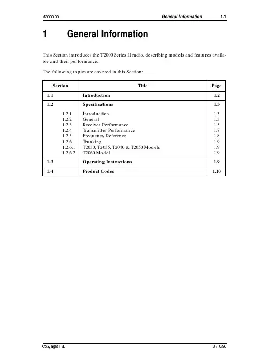
2 $This Section introduces the T2000 Series II radio, describing models and features availa-ble and their performance.The following topics are covered in this Section:Section Title Page 1.1Introduction 1.2 1.2Specifications 1.31.2.1 1.2.2 1.2.3 1.2.4 1.2.5 1.2.6 1.2.6.1 1.2.6.2IntroductionGeneralReceiver PerformanceTransmitter PerformanceFrequency ReferenceTrunkingT2030, T2035, T2040 & T2050 ModelsT2060 Model1.31.31.51.71.81.91.91.91.3Operating Instructions 1.9 1.4Product Codes 1.108 $ #The T2000 Series II is a high performance mobile two way radio. It covers ten frequency bands between 66 and 870MHz, and is available in both trunked and conventional mod-els.Operation of the T2000 is by handheld microphone, a press-to-talk switch and a range of front panel function keys. The T2020 and T2040 models are fitted with an LCD display and alphanumeric keypad.Most of the functions of the T2000 are microprocessor controlled. The system software is stored in a read only memory (ROM), while the data is stored in a non-volatile memory for ease of programming. Operational parameters can be programmed without opening the radio, via the front panel microphone socket.The T2000 uses a synthesiser with a single VCO switched between transmit and receive.A plug-in TCXO PCB is used to provide a highly stable reference frequency, and dual point modulation gives a flat modulation response at the synthesiser.The standard T2000 RF power output is 25W, except in the T2000-800 which delivers 15W. The receiver is electronically tuned across the entire frequency band and contains an IF noise blanker and RSSI facility. A maximum of 4W of audio is delivered to a 4Ωspeaker.The RF and logic PCBs are shielded from each other in a diecast aluminium chassis, and are connected by two plug-in looms. The T2000 top and bottom covers are also diecast aluminium.There is provision within the radio to mount option PCBs and a 9 or 15 way output con-nector which is used for options requiring connection to external equipment. Standard options include hands-free operation, line control interface, signalling and data trans-mission.The DC supply to the radio must be negative earth and may be between 10.8 and 16V. The T2000 is protected against reversal of the DC supply and is provided with overvolt-age protection.If further information is required about the T2000 or this Manual, it may be obtained from Tait Electronics Ltd or accredited agents. When requesting this information, please quote the equipment product code (e.g. T2010-512-002) and serial number. In the case of the Service Manual, quote the product code (e.g. M2000-00-300), and for circuit dia-grams quote the ‘Title’, ‘Internal Part Number’ (IPN) and ‘Issue’.8 & # #8 8 $ #The performance figures given are typical figures, unless otherwise indicated, for equip-ment operating at standard room temperature. Where applicable, the test methods used to obtain the following performance figures are those described in the European specifi-cation ETS 300-086.Details of test methods and the conditions which apply for type approval testing in all countries can be obtained from Tait Electronics Ltd.8 8 2Modulation Type.. FMFrequency Ranges:T2000-100..220 to 270MHzT2000-200..66 to 88MHzT2000-300..136 to 174MHzT2000-400..175 to 225MHzT2000-500..400 to 470MHzT2000-600..450 to 520MHzT2000-700..330 to 360MHzT2000-800..800 to 870MHz (Tx)..851 to 870MHz (Rx)T2000-900..360 to 400MHzT2000-000..500 to 530MHzFrequency Increment:All Except T2000-800.. 5 or 6.25kHzT2000-800..12.5kHzNumber Of Channels:T2010.. 4T2015..24T2020..100Bandwidth..7.5, 12 or 15kHzSwitching Range:T2000-200..22MHzT2000-300..38MHzT2000-400, T2000-100..50MHzT2000-500, T2000-600..70MHzT2000-700..30MHzT2000-800..70MHz (Tx)..19MHz (Rx)T2000-900..40MHzTx/Rx Offset:T2000-200..0 to 22MHzT2000-300..0 to 38MHzT2000-400, T2000-100..0 to 50MHzT2000-500, T2000-600..0 to 70MHzT2000-700..0 to 30MHzT2000-800..0 to 45MHzT2000-900..0 to 40MHzSupply V oltage:Operating Range..10.8V to 16V DCStandard Test V oltage..13.8V DCPolarity..negative earthPolarity & Overvoltage Protection..internal transorb crowbarBrown-out Recovery..<2s to full operation following supplyfluctuations below 10.8VSupply Current:Economy Mode..<270mA (T201X/T203X/T2060) or<350mA (T2020/T2040/T2050) Receiver:Squelched..320mA (T201X/T203X/T2060) or472mA (T2020/T2040/T2050) Full Audio.. 1.2ATransmit:T2000-200, -300, -400, -800..6AT2000-500.. 6.8AT2000-600..7AT2000-100, -700, -900.. 6.8AT2000-000..7.5ATx/Rx Changeover Switching..solid stateOperating Temperature Range ..-30ºC to +60ºC ambient Programming..clone or PC program via mic. socket Antenna:Impedance..50Ω (nominal)Connector..BNC (UHF optional on VHF radios only) Power/Speaker Connector..7 way automotive typeOptions Connector..9 or 15 way high density D-range(optional)Radio Unit Dimensions:Depth..150mmWidth..150mmHeight.. 45mmFront Panel Dimensions:Depth..25mmWidth..158mmHeight..51mmRemote Control Head Dimensions:Length..26mmWidth..159mmHeight..51mmWeight (radio & control head).. 1.2kg8 8 # #Type:All Except T2000-200..triple conversion superheterodyne T2000-200..dual conversion superheterodyne Sensitivity:12dB Sinad..better than -117dBm20dB Sinad (psophometric)..better than -113dBm20dB Quieting..better than -113dBmIF Amplifiers:Frequencies:T2000-200..10.7MHz and 455kHzT2000-100, -300, -400..27.7MHz, 10.7MHz and 455kHzT2000-500, -600, -700, -900, -000..49.1MHz, 10.7MHz and 455kHzT2000-800..61.9MHz, 10.7MHz and 455kHz First Local Oscillator Injection (with respect to signal):T2000-200, -300 ..high sideT2000-100, -400, -500, -600, -700, -800,..low side-900, -000Second Local Oscillator Injection (with respect to signal):T2000-100, -300, -400 ..high sideT2000-200, -500, -600, -700, -800, -900, -000..low sideThird Local Oscillator Injection (with respect to signal):T2000-100, -300, -400..low sideT2000-500, -600, -700 -800, -900, -000..low sideBandwidth:Narrow Band..7.5kHzMedium Band..12kHzWide Band ..15kHzSignal-to-Noise Ratio (with respect to 100% deviation, at RF level of -47dBm): Narrow Band..45dBMedium Band..48dBWide BandAll Except T2000-800..50dBT2000-800..45dBAudio:Minimum Load Impedance..2ΩRated Power (into 4Ω)..4W (at 1kHz)Distortion:@ Rated Power (1kHz)..<5%@ 0.5W (0.3 to 3.0kHz)..<3% (narrow band)<2.5% (medium band)<2% (wide band) Response ..within +1, -3dB of 6dB/octavede-emphasisBandwidth..300Hz to 3kHz Selectivity..better than 70dBSpurious Response AttenuationAll Except T2000-000, -800..75dB (80dB EIA)T2000-000..60dBT2000-800..70dB (70dB EIA) Intermodulation Response Attenuation..66dB (75dB EIA)Spurious Emissions..better than -57dBm (conducted & radiated to 1GHz)Spurious Emissions..better than -47dBm (conducted & radiated 1 to 4GHz)Blocking..better than -23dBmCo-channel Rejection:Narrow Band..better than 9dBMedium Band..better than 7dBWide Band..better than 6dBGroup Delay..±50µs (300Hz to 3kHz) Squelch:Preset Level ..11dB sinadRatio..>70dBV oting Levels..>20dB sinad(applies to T2020 only)8 8" #Power Output:Maximum:All Except T2000-800..30WT2000-8000..25WHigh (high setting):All Except T2000-800..25WT2000-8000..15W.Low (low setting):T2000-200, -300, -400.. 1 to 25WT2000-100, -500, -600, -700, -900.. 5 to 25WT2000-800.. 5 to 15WLow Power V ersion.. 1 to 7W (T2000-500, -600)Duty Cycle (33%).. 2 minutes Tx, 4 minutes RxLock Up Time (synthesiser)..25ms (from PTT to 90% output powerwithin 2kHz, not including micro.delay)Spurious Emissions..better than -36dBm(conducted & radiated to 1GHz)Spurious Emissions..better than -30dBm(conducted & radiated to 1 to 4GHz)Adjacent Channel Power:Narrow Band ..better than -65dBcMedium Band..-70dBcWide Band..-80dBcGroup Delay..+200/-50µs (300Hz to 3kHz) Modulation System:Type ..direct FMDeviation Limiting:Narrow Band..±2.5kHz (peak) max.Medium Band..±4kHz (peak) max.Wide Band..±5kHz (peak) max.Bandwidth:Narrow Band..300Hz to 2.55kHz below limiting or450Hz to 2.55kHz in limiting Medium & Wide Band..300Hz to 3kHz below limiting or450Hz to 3kHz in limiting Responses:In Limiting..within +0dB, -4dB of maximumsystem deviationBelow Limiting..within +1, -3dB of 6dB/octavepre-emphasisAbove 3kHz..greater than 25dB/octave roll-offAudio:Microphone Type..dynamic or electretInput For 60% Deviation .. 1.5mVrms maximum (at 1kHz)Distortion..5%Hum & Noise:All Except T2000-800:Narrow Band ..39dB Medium Band ..43dB Wide Band ..45dB T2000-800:Wide Band ..40dBMismatch Capability:Ruggedness.. 2 minutes transmission into infinite VSWRStability..VSWR 5:1 (all phase angles)Transmit Timer (non-trunking models)..programmable up to 4 minutes, or continuous.8 8+3 ( # #Oscillator Frequency..12.8MHz Crystal Stability And Source Details..see table below:*.Not fitted to T2000-200 due to low modulatibility.†.Fitted only to 400MHz versions and above, due to low modulatibility.Product CodeFrequency T olerance(ppm)T emperature Range (ºC)Frequency SourceT2XX-XX 1±5-10 to +60TE/45 xtalT2XX-XX 3*±3-30 to +60VXO-2605A Module T2XX-XX 5±2.5-30 to +60VXO-2605A-1 Module †T2XX-XX 6±2.0-30 to +60TDC 60281 Module †8 8- 98 8-8 1 1: 1 +: 1"1 4 1+1Data Modulation ..as per MPT1317Data Deviation (Tx: 60% full system deviation):Narrow Band.. 1.5kHzMedium Band.. 2.4kHzWide Band..3kHz8 8-8 1-1System..LTR® trunked1, systems x groups = 24 Data Deviation (Tx)..1kHz8 *& $ #Refer to the User’s Guide supplied with the radio. These are also available separately under the following IPNs:T2010/T2015459-20100-0XT2020459-20200-0XT2030/T2035459-20300-0XT2040459-20400-0XT2060459-20600-0XComprehensive Operator’s Manuals are also available for T2020 and T2040 radios. These Manuals cover such topics as advanced user operations and the use of trunked radios for data applications. These are available under the following IPNs:T2020409-20200-0XT2040409-20400-0X1.LTR® is a trademark of E F Johnson & Co.8" # )The 3 groups of digits in a T2000 product code provide information about the radio’s model, RF type and options fitted, according to the conventions described below.The following explanation of the T2000 product codes is not intended to suggest that any combination of features is necessarily available in any one radio. For details regard-ing availability of specific T2000 radios, consult your nearest Tait dealer or subsidiary.The Model group indicates the basic features of the radio, as follows:T20XX-XXX-XXX T2010 4 channelsT201524 channelsT2020100 channelsT2030 4 calls, all preset trunkedT20351000 calls, including 20 preset trunkedT2040dialled calls trunkedT2050dual mode T2040 or T2020 operation trunked, non-trunkedT2060LTR®, systems x groups = 24trunked3 &RF Type group uses 3 digits to indicate the basic RF configuration of the radio.The first digit in the RF Type group designates frequency band.T20XX-X XX-XXX‘1’ for 220 to 270MHz‘2’ for 66 to 88MHz‘3’ for 136 to 174MHz‘4’ for 175 to 225MHz‘5’ for 400 to 470MHz‘6’ for 450 to 520MHz‘7’ for 330 to 360MHz‘8’ for800 to 870MHz transmit851 to 870MHz receive‘9’ for 360 to 400MHz‘0’ for 500 to 530MHzThe second digit in the RF Type group designates radio IF bandwidth.T20XX-X X X-XXX‘1’ for wide band (15kHz)‘2’ for narrow band (7.5kHz)‘3’ for medium band (12.5kHz)The third digit in the RF Type group designates frequency stability.T20XX-XX X-XXX refer to “Frequency Reference” on page 1.8.*&T20XX-XXX-XXX The third group of digits covers a wide range of software and mar-ket specific options. The large number of options and their frequentchanges preclude listing them here.。
东芝2000学习(1)

二、设置试剂位
Reagent→View 查看试剂位使用情况
Reagent→R1→双击空试剂位
选取新上项目→试剂信息自动对应→OK (R2同此步骤)
各项目尽量均匀分布在内外盘以充分调动双针保证测速;同一项目R1和R2在相应盘的相同圈上。
三、输入定标信息
C/C→双击空通道→依次输入校准品名称、架子号、 校准品安装方式、校准品等级数等信息→OK
在Base界面输入新项目的基础参数(数据详见参数表), 如反应模式、主副波长、读数点、样本量、试剂所在盘、
试剂种类、试剂量、校正因子、小数点位数、单位等。
2 1
3
在Calibration界面中选择定标模式(因数法选Factor)、 输入因数、定标液、重复次数(推荐3次)、加样量。
单点定标选(Linear)、多点定标选(Logit-4)、选择 定标液,输入水平数、定标液浓度和定标偏差检测等。
如果只做样本要检查 是否有定标请求
七、结果查看
Database→选中样本结果→选中查询项目 →Rxn Graph查看反应曲线
Calibration→选中定标项目查看定标曲线和数据
东芝TBA-2000FR 操作说明
仪器外观
搅拌区
仪器布局
清洗站
试剂针
R2 R1
样本针 反应盘
试剂舱旋转按钮
仪器主界面
试剂位设置ቤተ መጻሕፍቲ ባይዱ定标设置
项目参数 实验结果查看
开机清洗 报错提醒
标本申请 关机清洗
定标结果查看
急诊
一、设置通道
Reagent→Library→双击空通道→输入试剂名称、 试剂瓶规格、报警余量等信息→OK(R2同此步骤)
1
五、定标
东芝TLP-X3000投影机维修手册
东芝TLP-X3000投影机维修手册FILE NO. 330-200711GRSERVICE MANUAL3LCD DATA PROJECTORTLP-X2000E/B/U/C TLP-X2500E/B/U/C TLP-X3000E/B/U/CThe above models are classified as green product (s) (*1), as indicated by the underlined serial number (s). This Service Manual describes replacement parts for green product (s). When repairing any green product (s), use the parts described in this manual and lead-free solder (*2). For (*1) and (*2) , see the next page.TOSHIBA CORPORATIONPublished in Japan, July 2007 GREENIContentsTable of ContentsChapter 1Specifications Using the Menus Names of the Terminals on the Rear Panel Name of each part on document camera List of Supported Signals 1-1 1-1 1-3 1-4 1-5 1-6 2-1 2-1 2-2 2-3 2-15 3-1 3-1 4-1 4-1Chapter 2Replaceable Part Hierarchy Required Tools Parts Replacement Replacement of optical partsChapter 3SINGOWS 2000Chapter 4Firmware UpgradeChapter 5Wiring Diagram Block Diagram5-15-1 5-2Chapter 6LED Display Troubleshooting Operation of Power Supply 6-16-1 6-2 6-9Chapter 7Electrical adjustment7-17- 1Chapter 8Functional Test8-18-1Chapter 9Spare Parts List9-19-1IIChapter 1Chapter 1Specifications1-1aChapter 1Chapter 1Specifications1-1bChapter 1Chapter 1Specifications1-1cChapter 11-2Chapter 1Using the Menus1-3Chapter 1Names of the Terminals on the Rear Panel1-4Chapter 1List of Supported Signals1-5Chapter 11-6Chapter 2Replaceable Part HierarchyReplaceable Part Hierarchy The flow chart below shows what parts must be removed to access each replaceable part in the projector. The parts on the first level (/doc/e114169452.html,mp cover) are accessible without removing any other parts. The move levels down that a part is, the more parts you need to remove in order to access it. Start Lamp cover Control panel Lamp Bracket LED board Cover for Power Power Main Optical Engine Intake Fan Exhaust Fan Powe Filter FanChapter 2Top coverPCB MainFront panelRemocon receiver PCB SensorLCD FanFoot ADJLens coverSpeakerDoor SWPBS FanCamera assyCamera Main Camera KEY Camera CMOS Camera LEDBalast & FAN assyBalast Fan Lamp Driver Rear panel Thermal SWLensColor wheel Power Filter LCD PanelLCD Filter2-1Chapter 2Required ToolsItemDriver bit (?) No 2PhotoBox driver M3Driver bit (?) No 0Torque driver bit (?) No 2NippersCutting pliers2-2Chapter 2Parts Replacement/doc/e114169452.html,mp No Figure ExplanationRemove two lamp cover screws.1Remove three lamp screws.2Lamp is pulled out.2.Top Cover Remove five screws at the bottom. Remove two screws at the rear.Remove a screw at the right.Remove a screw at the left.Top cover is removed.32-3Chapter 23.Main Board Step Figure ExplanationAll the connectors on a main board unit are removed. 1Remove five screws.Remove two screws at the rear cover.2Main board is removed.32-4Chapter 24.Main Power Unit Step Figure Explanation Remove four screws.1Cover & Power Intake FAN are removed.2Remove two screws.Power Intake FAN are removed.Remove a screw.4Main Power Unit is taken out.52-5Chapter 25.PBS & Ballast FANs Step Figure Explanation Remove six screws.1Balast & FAN assy is taken out.2Remove two screws.Remove two screws.3Ballast FANs are removed.4PBS FANs are removed.2-6Chapter 26.Exhaust FanRemove no screw.1Note. May be very tight.Exhaust Fan is removed.27.BallastRemove two screws.1Cover is removed.Pinch a stud with cutting pliers. (4 points) Then pull up PC Board.Ballast is removed.32-7Chapter 28.Filter Power Step Figure ExplanationRemove two screws.1Cover is removed.2Filter Power is taken out.32-8。
东芝电磁炉维修手册

东芝电磁炉维修手册内容介绍本<<手册>>是针对东芝电子设计开发电磁炉售后服务用途而编写,共分三大部分,第一部分主要介绍电磁加热的原理及088系列电磁炉简介,第二部分为088系列电磁炉原理分析,第三部分介绍电路的检测方法及标准,并针对检测时出现的不良情况给出对策,而且介绍一些故障案例供维修时作参考。
目录一、简介1.1 电磁加热原理1.2 088系列简介二、原理分析2.1 特殊零件简介2.1.1 LM339集成电路2.1.2 IGBT2.2 电路方框图2.3 主回路原理分析2.4 振荡电路2.5 IGBT激励电路2.6 PWM脉宽调控电路2.7 同步电路2.8 加热开关控制2.9 VAC检测电路2.10 电流检测电路2.11 VCE检测电路2.12 浪涌电压监测电路2.13 过零检测2.14 锅底温度监测电路2.15 IGBT温度监测电路2.16 散热系统2.17 主电源2.18辅助电源2.19 报警电路三、故障维修3.1 故障代码表3.2 主板检测标准3.2.1主板检测表3.2.2主板测试不合格对策3.3 故障案例3.3.1 故障现象1一、简介1.1 电磁加热原理电磁灶是一种利用电磁感应原理将电能-磁能-热能的厨房电器。
在电磁灶内部,由整流电路将50/60Hz的交流电压变成直流电压,再经过控制电路将直流电压转换成频率为20-40KHz的高频电压,高速变化的电流流过线圈会产生高速变化的磁场,当磁场内的磁力线通过金属器皿(导磁又导电材料)底部金属体内产生无数的小涡流,使器皿本身自行高速发热,然后再加热器皿内的东西。
1.2 088系列简介088系列是由东芝电子技术开发制造厂设计开发的新一代电磁炉,介面有LED发光二极管显示模式、LED数码显示模式、LCD液晶显示模式、VFD荧光显示模式机种。
操作功能有加热火力调节、自动恒温设定、定时关机、预约开/关机、预置操作模式、自动泡茶、自动煮饭、自动煲粥、自动煲汤及煎、炸、烤、火锅等料理功能机种。
东芝笔记本维修手册Satellite_A20_Series(英文版)
东芝笔记本维修⼿册Satellite_A20_Series(英⽂版)FIELD REPLACEABLE UNIT DOCUMENTATIONSatellite TMA20 Seriesmake sure that the main battery and AC adaptor is not connected to the unit and the environment in which you are working on is protected fromElectro-Static Discharge(ESD).A20 SeriesOPTIONAL PC CARD REMOVAL1. Press the eject button for the PC card you want to remove.2. Press the extended eject button to pop the PC Card out.3. Grasp the PC card and remove it.SELECT BAY REMOVAL1. Turn the computer upside down.2. Slide the release lever in the direction of the arrow.3. Pull out the select bay drive .1. Turn the computer upside down as shown.2. Slide the battery release lever in the direction of the arrow.3. Lift out the battery .NOTE : Before removing any PC Card device, make sure it is “STOPPED” in the PC Card manager.DV-R/-RW DRIVE DISASSEMBL Y1. Remove five M2x3 silver flat head screws securing the base cover and lift out the cover .2. Remove two M2x8 silver screws securing the connector cover.3. Remove the connector cover and the connector from the DVD-R/-RW drive.DVD-R/-RW M2x3 silver flat head screwsConnector cover M2x8 silver screwsConnectorBase coverA20 SeriesRelease leverSelect bay deviceEject buttonPC card1. Turn the computer upside down.2. Remove one M2.5x4 black flat head screw securing HDD cover.3. Remove the HDD cover .HDD REMOVALA20 Series1. Peel off the plastic insulator covering the modem board.2. Remove two M2x4 flat head silver screws securing the modem board3. Disconnect the modem board from PJ2900 on the system board and then the modem cable from JP1 on the modem board. MODEM BOARD REMOVAL4. Grasp the HDD bracket handle and pull to disconnect the HDD assembly.5. Lift the HDD assembly out of the HDD bay.6. Remove four M3x4 brass flat head screwssecuring the HDD bracket to the drive.7. Lift out the HDD .HDD coverboardM2x4 flat head silver screwsM3x4 Flat head screwsHDD bracketHDD bracket HDD4. Remove two M2x18 black screws securing theCPU fin.5. Lift out the CPU Fin.1. Insert a flat head screwdriver to the CPU lockand rotate it counter-clockwise to unlock the CPU.2. Lift out the CPU.CPU FIN REMOVAL1. Turn the computer upside down.2. Remove two M2.5x6 black flat head screwssecuringthe CPU fin cover.3. Lift out the CPU fin cover.A20 SeriesCPU coverCPU finCOOLING FAN REMOVALCPU1. Remove M2.5x4 black flat head screws securingthe FAN cover.2. Lift out the FAN cover.A20 SeriesCOOLING FAN REMOV AL 1. Remove two M2.5x6 black flat head screws securing the cooling fan.2. Lift out the cooling fan.Cooling FANKEYBOARD REMOVAL1. Turn the computer right side up and open the display panel.2. Using the case separator , unlatch thekeyboard holder at the top of the keyboard.Keyboard holderKeyboard KEYBOARD REMOVAL3. Remove two M2.5x4 black flat head screws securing the keyboard.4. Remove one M2.5x4 black flat head screw securing the keyboard holder plate and lift out the plate. Keyboard holder plate5. Lift out the keyboard and set it as shown above.6. Remove the oneM2.5x6 black flat head screw securing the keyboard support plate and lift out the plate.M2.5x6 black flat head screwsKEYBOARD REMOVAL 7. Set the keyboard as shown above..8. Disconnect the keyboard cable from PJ123 on the system board.9. Lift out the keyboard .A20 SeriesKeyboard MEMORY MODULE REMOV AL1. Lift up the plastic insulator covering the memory slot.2. Spread the memory clipsoutward and pull the memory module out of the connector on a 30degree angle.Memory moduleMemory clipsPlasticinsulator1. Remove two M2.5x4 black flat head screws securing the sensor switch board.2. Disconnect theswitch board cable from PJ2027 on the back side of the switch board.3. Lift out the switch board .switch board1. Lift up the plastic insulator covering the wireless LAN card.2. Disconnect the black and white coax from the wireless LAN card.3. Spread the Mini-PCI connector clipsand pull the Wireless LAN card out of the connector about 30 degree angle.Black coax cableWhite coax cable Wireless LAN cardA20 SeriesTOUCH PAD REMOVAL 1. Disconnect the touch pad cable from PJ2004 on the system board.2. Remove one M2.5x4 black flat head screw securing the touch pad.3. Lift out the touch pad .1. Turn the computer upside down.2. Disconnect the sub fan cable from PJ8770.2. Remove twenty three screws securing the bottom cover: - 5 M2.5x4 black flat head screws - 10 M2.5x6 black flat head screws - 8 M2.5x20 black screwsM2.5x4 black flat head screws M2.5x20 black screwsM2.5x6 black flat head screws3. Turn the computer right side up.4. Peel off the glass tape . Disconnect the LCD/FL cable from PJ5000/PJ5001 and Left/Right speaker cables fromPJ3003/PJ3002 on the system board.5. Remove four M2.5x6 black flat head screws securing the top cover and lift out the top cover.M2.5x6 black flat head screwsPJ5000/PJ5001Left/Right speakercable PJ3002Touch pad M2.5x4 black flat head screw FRONT MEMBRANE SWITCH REMOVAL1. Disconnect the membrane switch cable from PJ2025 on the system board.2. Remove two M2.5x4 black flat head screws securing the front membrane switch assembly.3. Lift out the front membrane switch assembly .Membrane cablePJ2025Sub fan cable PJ8770SOUND BOARD REMOVAL1. Remove one M2.5x6 black flat head screw securing the sound board.2. Gently lift up the sound board and disconnect the two sound I/F cablesfrom PJ2901/2902 on the sound board..A20 Series1. Disconnect the RTC battery cable from PJ9999 on the system board.3. Lift out the RTC battery .1. Disconnect the USB board cable from PJ2029 on the USB board.2. Remove two M2.5x6 black flat head screws securing the USB board.3. Lift out the USB board and disconnect the USB harness.RTC batteryRTC cablePJ9999M2.5x6 black flat head screwsUSB board Sound I/F cables1. Disconnect the DC IN jack from PJ8800 and the switch board cable from PJ2026 on the system board.2. Disconnect the sound I/F cables from PJ2903/2904 and the USB board cable from PJ2028 on the system board.SYSTEM BOARD REMOVALSound I/F cables DC-In jack PJ2028PJ2903PJ2026Switch board cableUSB harness PJ40021. Remove one M2.5x6 black flat head screw securing the plastic brace and the system board.2. Remove two M2.5x6 black flat head screws securing the system board.3. Gently lift up the system board from the right hand side and lift it out of the bottom cover.SYSTEM BOARD REMOVALA20 SeriesPlastic braceA20 SeriesFL INVERTER AND 15” LCD REMOV AL15” DISPLAY MASK REMOVALFL inverter board.2. Carefully lift up the FL inverter board anddisconnect the LCD /FL cable from CN1 and the FL cable from CN2.3. Remove four M2X5 silver flat head screws securing the LCD module assembly.4. Carefully rotate out the top of the LCD module enough to access the display cable6. Peel off the tape securing the LCD/FL cable and disconnect the cable.7. Remove four M2x3 silver flat head screws securing the left and right LCD brackets and separate the brackets Mask sealsDisplay maskLCD1. Remove two mask seals at the bottom corners of the display assembly using a pair of fine-tipped tweezers.2. Remove two M2.5x6 black flat head screws securing the display mask.3. There are 23 latches securing the display mask .Carefully insert your fingers between the mask and the LCD panel and pry open the latches starting from the bottom six latches , to the five latches on the right and left sides , ending with the six top latches .。
大吉2000系列维修手册5
When in test mode, connect the antenna socket to a dummy load to prevent interference with trunking systems. Avoid testing on channels in use locally.
When using with LTR or DCS, the deviation meter must have a good low frequency response, to avoid incorrect deviation readings. • Sinad meter or audio distortion analyser, 1kHz notch type (e.g. HP334A, HP339A or Helper Instruments Sinadder). • AC millivoltmeter (e.g. Trio VT-106). • Digital multimeter (e.g. Fluke 75). • 20MHz dual channel oscilloscope and X10 . X1 scope probes (e.g. Trio CS1022). • RF power meter, 50Ω; RF detecting element 50W and 5W for appropriate frequency ranges (e.g. Bird Meter 6154 or 611). • RF power attenuator, 50Ω, total attenuation 30dB (e.g. Weinschel 40-40-33 30dB, 150W). • Microphone test box (refer to Figure 4.1). A multifunction test set may be used as long as it has the appropriate function to perform the calibration correctly e.g. Rhode & Schwarz CMS52 Radio Communications Test Set, with a high stability oscillator.
东芝复印机维修手册
东芝复印机维修手册东芝复印机维修代码大全同时按0和1键打开电源面板指示灯全部点亮,按清除/停止键解除同时按0和2键打开电源机器进入老化方式,显示AG,同时按09键解除同时按0 3或04键打开电源机器进入输入/输出检查方式,显示CH,输入不同的代码可以启动不同的部件,例如03-33暴光灯检查同时按0和6键打开电源强制启动《定影器不加热》同时按0和7键打开电源自动进稿器老化方式,显示AG,按09退出按03/04键同时打开电源,进入输入/输出检查状态显示CH,退出同时按09键1主电机ON 11 OFF2供纸辊离合器ON 12 OFF3定位辊离合器ON 13 OFF6调色剂电机ON 16 OFF7冷却风扇ON 17 OFF10 总计数器按P键20扫描电机按P键移动50% 再按P键200%21 镜头电机按P键移动50%在按P键200%22 反光镜电机按P键移动50%再按P键200%31转印输出按P键ON再按P键OFF32 分离输出按P键ON再按P键OFF33嚗光灯输出按P键ON再按P键OFF34预转印偏压按P键ON再按P键OFF40 上纸盒电机按P键ON再按P键OFF41 上纸盒供纸离合器按P键ON再按P键OFF43 下纸盒电机按P键ON再按P键OFF44 下纸盒供纸离合器按P键ON再按P键OFF以上是检测代码,一般只使用03/04 05 08,老化方式机器空运转。
1、更换载体同时按05, 打开电源开关, 面板显示AJ, 键入调整模式N按复印允镜鼻爸担?自动)调整,键入修改值,按插入键将修改值存入内存,按3+4 复印--0 TD传感器自动调整--键入0,按复印键鼓和显影器工作大约2分钟面板显示数开始自动改变短时间后显示数停止改变。
--显示值=24(2.4±0.5v), 按插入键存入内存,按09退出---------------- ----------------退出自诊断05 模式: 键入"09"----------清除保养信号------同时按08, 打开电源开关, 面板显示AD, 键入调整模式N按复印键显示当前值,进行(自动)调整,键入修改值,按插入键将修改值存入内存,按3+4 复印----69--PM(保养周期)间隔设定--范围: 0~999,999 缺省值=0---------- 79--当前PM计数显示----范围: 0~999,999 缺省值=0---- 当79显示的数值达到69设定的数值时保养信号出现,重新设定保养周期可消除保养信号----------------退出自诊断08 设定模式: 键入"09"关于此项的补充0+5开机东芝复印机部分调整代码1 手动曝光调整100% 范围0~255 标准1282 手动曝光调整154% 范围0~255 标准1283 手动曝光调整50% 范围0~255 标准1284 手动曝光调整200% 范围0~255 标准1285 自动曝光调整100% 范围0~255 标准1286 自动曝光调整154% 范围0~255 标准1287 自动曝光调整50% 范围0~255 标准1288 自动曝光调整200% 范围0~255 标准12814 图像曝光调整100% 范围0~255 标准12815 图像曝光调整154% 范围0~255 标准12816 图像曝光调整50% 范围0~255 标准12817 图像曝光调整200% 范围0~255 标准12838 栅偏压输出范围0~255 标准12839 转印电压调整范围0~255 标准12840 分离偏压调整范围0~255 标准12842 栅偏压调整范围0~255 标准128* 49 自动曝光自动调整* 0 自动墨粉调整设置成24* 90 自动墨粉调整范围0~255 标准128 (表示自动墨粉传感器的调整量)0+8开机* 69 PM计数器设置方式0-999,999 初始值0 0:PM计数器无效否则PM请求79 当前PM计数器值0-999,999东芝复印机曝光量调整代码按0、5开机1--手动100%曝光量调整----范围: 0~255, 缺省值=128-------- 2--手动154%曝光量调整----范围: 0~255, 缺省值=128-------- 3--手动50%曝光量调整----范围: 0~255, 缺省值=128-------- 4--手动200%曝光量调整----范围: 0~255, 缺省值=128-------- 5--自动100%曝光量调整----范围: 0~255, 缺省值=128-------- 6--自动154%曝光量调整----范围: 0~255, 缺省值=128-------- 7--自动50%曝光量调整----范围: 0~255, 缺省值=128-------- 8--自动200%曝光量调整----范围: 0~255, 缺省值=128--------------------9--曝光量上限调整----范围: 0~255, 缺省值=255--------10--曝光量下限调整----范围: 0~255, 缺省值=0--------14--照片100%曝光量调整----范围: 0~255, 缺省值=128-------- 15--照片154%曝光量调整--范围: 0~255, 缺省值=128-------- 16--照片50%曝光量调整--范围: 0~255, 缺省值=128--------17--照片200%曝光量调整----范围: 0~255, 缺省值=128----C1--主电机锁住------------------------C21--光学系统没能完成初始化,光学系统锁住------------------------ C26--曝光灯烧坏------------------------C32--开箱(UA)TD传感器自动调整失败------------------------ C41--电源接通时,定影热敏电阻异常或者定影灯开路------------------------C43--在预热期间,或者在预热完成后定影热敏电阻异常------------------------C44--在预热期间,或者在预热完成后定影灯开路------------------------C54--分页器-和主CPU通信错误------------------------C55--自动进稿器ADF-和主CPU通信错误------------------------C71--ADF主电机锁住------------------------C72--由定位传感器检测出的不良调整------------------------C73--EEPROM初始化不良------------------------C81--分页器输纸电机异常------------------------C82--分页器斗移位电机异常------------------------C83--分页器上限错误------------------------C84--分页器下限错误------------------------C85--分页器原位传感器错误------------------------C86--分页器移位传感器错误------------------------C94--在(CH,AJ)模式时,光学系统没能完成初始化,光学系统锁住--------------------E1--机内卡纸------E2--定影附近卡纸------E3--电源ON时有纸保留在复印机内------E4--复印期间前门盖被打开------E5--对位辊附近卡纸------E14--下纸盒进纸卡纸------E71--ADF原稿进稿部分卡纸------E72--ADF原稿传输部分卡纸------E73--ADF原稿排出部分卡纸------E75--ADF 2合1(第2张在原稿传输部分)卡纸------E81--分页器输纸部分复印纸到达时间超过卡纸,纸未到达传感器------E82--分页器输纸部分复印纸等待时间超过卡纸,纸停在传感器------1568的误码表“清除卡纸”或“检修请求”符号一闪一闪时,同时按下:“CLEAR/STOP”和“8”键,会显示以下错误码:1.复印机纸路卡纸错误代码内容备考E01复印机机体内卡纸包括旁送卡纸(旁送LED亮)E02定影器附近卡纸E03打开电源时机内卡纸E05未到达定位开关卡纸在PFU供纸通过传输辊之后还是由PPC 供纸之后?2.在供纸部分卡纸错误代码内容备考 E14下纸盒卡纸(PFU)纸未到达传输辊3.在ADF传输路径中卡纸错误代码内容备考 E71在ADF原稿供纸部分卡纸E72在ADF原稿传输部分卡纸E73在ADF原稿排纸部分卡纸E752合1(第2张原稿在供纸部分卡纸)4。
东芝2000系列维修手册
东芝2000系列维修手册东芝2000系列维修手册一、介绍本维修手册旨在为东芝2000系列产品的维修人员提供详细的维修指南和操作步骤。
本手册分为以下几个章节:安全注意事项、故障诊断、维修步骤、零件替换和维护保养。
二、安全注意事项1:在执行任何维修工作前,务必断开电源并拔掉电源插头。
2:使用绝缘工具和个人防护装备,确保安全操作。
3:请遵守国家和地方的安全法规和标准。
4:请确保操作环境干燥、通风良好,并远离易燃和易爆物品。
5:在执行维修工作时,禁止吸烟、使用明火和产生静电。
6:请仔细阅读产品手册和使用说明书,熟悉产品的功能和操作步骤。
三、故障诊断1:故障现象描述:清楚描述产品故障的具体现象和表现。
2:故障原因分析:基于故障现象,分析可能的故障原因。
3:故障诊断步骤:根据故障现象和可能的原因,进行逐步的故障诊断。
4:测试仪器及工具:列出常用的测试仪器和工具,如万用表、电源电压测试仪等。
四、维修步骤1:拆卸步骤:按照产品结构,详细列出拆卸产品的步骤。
2:零件替换:指导维修人员如何正确替换故障零件,并注意事项。
3:组件装配:指导维修人员如何正确组装产品以确保正常运行。
五、零件替换1:零件清单:列出常见故障零件的名称和编号。
2:零件替换步骤:详细描述如何替换故障零件,并注明注意事项。
3:零件供应信息:提供可靠的零件供应商和联系方式。
六、维护保养1:清洁步骤:指导维修人员如何正确清洁产品,并注明注意事项。
2:润滑步骤:如适用,在此部分指导维修人员如何正确润滑产品。
附件:本文档涉及的附件包括:1:产品结构图2:故障诊断流程图3:零件替换示意图法律名词及注释:1:依法运作:指根据法律的要求,合法进行操作。
2:保修期限:指产品保修期的有效时间。
3:免责声明:指相关方对于产品使用过程中的损失不承担责任的声明。