Dell Storage SC4020存储阵列白皮书
Dell Storage Center SC4020 存储系统 用户手册

SC4020 存储系统
用户手册
注、小心和警告
注: “注”表示可以帮助您更好地使用计算机的重要信息。 小心: “小心”表示可能会损坏硬件或导致数据丢失,并说明如何避免此类问题。 警告: “警告”表示可能会造成财产损失、人身伤害甚至死亡。
版权所有 © 2015 Dell Inc. 保留所有权利。 本产品受美国、国际版权和知识产权法律保护。 Dell™ 和 Dell 徽标是 Dell Inc. 在美国和 / 或其他管辖区域的商标。所有此处提及的其他商标和产品名称可能是其各自所属公司的商标。 2015 ......................................................................................................................... 24 故障转移行为..................................................................................................................................24 多路径 IO........................................................................................................................................24
2 连接前端................................................................................................................ 20
Dell Storage Center SCv2000 和 SCv2020 存储系统 用户手册
目录
关于本指南.................................................................................................................. 5
1 关于 SCv2000/SCv2020 存储系统.......................................................................7
SCv2000/SCv2020 存储系统监测和诊断程序....................................................................................... 7 SCv2000/SCv2020 存储系统硬件......................................................................................................... 7
修订历史记录.......................................................................................................................................... 5 读者对象................................................................................................................... 5 相关出版物............................................................................................................................................. 5
爱数存储柜产品白皮书

爱数存储柜 产品白皮书上海爱数软件有限公司 二〇〇八年六月十日目录摘要 (4)第一章产品介绍 (5)1.1 产品 (5)1.11.2 版本简介 (6)1.2第二章产品功能 (8)2.1 存储柜介绍 (8)2.12.2 备份功能简介 (8)2.22.2.1 操作系统保护 (8)2.2.2 应用系统保护 (8)2.2.3 文件数据保护 (9)2.2.4 邮件数据备份 (9)2.2.5 存储柜数据同步 (9)2.2.6 支持单一控制台管理 (9)2.2.7 丰富的备份和恢复机制 (10)2.2.8 多种客户端类型 (10)2.2.9 支持多存储柜数据同步 (10)2.3 存储功能简介 (10)2.32.3.1 多种类型RAID支持 (10)2.3.2 支持无盘启动 (11)2.3.3 虚拟逻辑卷 (11)2.3.4 支持NAS应用 (11)2.3.5 支持IPSAN应用 (11)2.3.6 支持扩展 (11)2.3.7 支持双机 (12)2.3.8 支持冗余和热插拔 (12)2.3.9 支持系统休眠 (12)2.3.10 支持UPS连接 (12)2.3.11 支持镜像 (12)2.3.12 支持快照 (12)2.3.12 支持SNMP管理 (12)2.4 存储柜其它功能简介 (12)2.42.4.1 丰富的日志管理 (12)2.4.2 丰富的用户权限管理 (13)2.4.2 WEB管理 (13)2.4.3 网络管理 (13)2.4.4 在线帮助 (13)2.4.5 语言切换 (13)2.4.6 升级更新 (13)2.4.7 系统告警 (13)2.4.8 系统配置备份与恢复 (14)2.5 爱数存储柜特点 (14)2.51.5.1 高性能 (14)1.5.2 可管理性 (14)1.5.3 可靠性 (14)1.5.4 可伸缩性 (15)1.5.5 可维护性 (15)1.5.6 安全性 (16)1.5.7 经济性 (16)第三章配置和模块 (17)3.1 产品型号和配置简介 (17)3.13.2 产品销售模块简介 (18)3.2摘要上海爱数软件有限公司,是专注于数据保护产品开发、生产和服务的厂商,成立于2003年,主要向企业级用户提供数据保护相关产品和服务。
Dell入门级存储阵列SCv2000系列白皮书
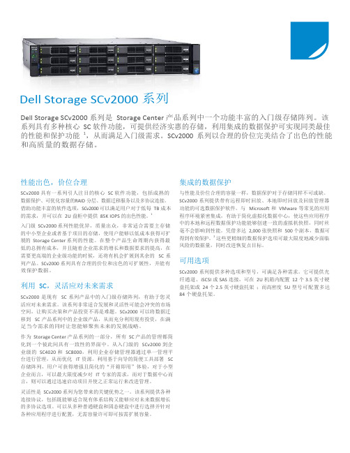
Dell Storage SCv2000 系列Dell Storage SCv2000 系列是Storage Center 产品系列中一个功能丰富的入门级存储阵列。
该系列具有多种核心SC 软件功能,可提供经济实惠的存储,利用集成的数据保护可实现同类最佳的性能和保护功能1,从而满足入门级需求。
SCv2000 系列以合理的价位完美结合了出色的性能和高质量的数据存储。
性能出色,价位合理SCv2000 具有一系列引人注目的核心SC 软件功能,包括成熟的数据保护、可优化容量的RAID 分层、数据迁移服务以及多协议连接。
借助功能丰富的软件选项,SCv2000 可以满足用户对于低每TB 成本的需求,并可以在2U 盘柜中提供85K IOPS 的出色性能。
1入门级SCv2000 系列性能优异,质量出众,非常适合需要主存储的中小型企业或者基于项目的存储,使用户能够以低成本获得可扩展的Storage Center 系列的性能。
在整个产品生命周期内获得最低的总拥有成本,并且随着企业需求的增长和数据要求的提高,在需要更高端的企业级功能的时候,还将有机会扩展到其余的SC 系列产品。
SCv2000 系列具有合理的价位和出色的可扩展性,并能有效保护数据。
利用SC,灵活应对未来需求SCv2000 是现有SC 系列产品中的入门级存储阵列,有助于您灵活应对未来需求。
该系列非常适合发展和灵活性可能会冲突的市场空间,让购买决策和产品投资不再是难题。
SCv2000 可以将数据迁移到SC 产品系列中的企业级产品,从而充分利用现有投资,在满足当今需求的同时让您能够聚焦未来的发展战略。
作为Storage Center 产品系列的一部分,所有SC 产品的管理都简化到一个彼此间具有一致性的界面中。
从入门级的SCv2000 到企业级的SC4020 和SC8000,利用企业存储管理器通过单一管理平台进行管理,从而优化IT 资源。
利用基于向导的简便工具部署SC 存储阵列,用户可获得增强且简化的“开箱即用”体验,对于小型企业而言,可以最大限度减少对IT 专家的需求,而对于数据中心而言,则可以通过迅速启动项目并使之正常运行来改进管理。
戴尔SC4020-企业存储的新生
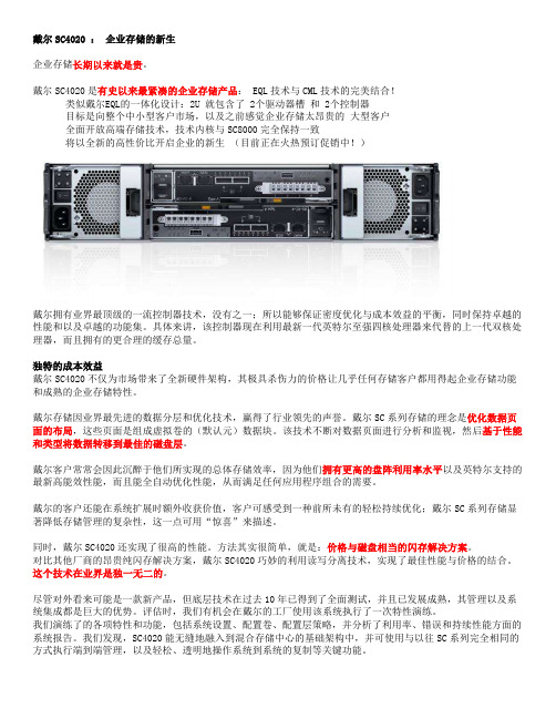
戴尔SC4020 :企业存储的新生企业存储长期以来就是贵。
戴尔SC4020是有史以来最紧凑的企业存储产品: EQL技术与CML技术的完美结合!类似戴尔EQL的一体化设计:2U 就包含了 2个驱动器槽和 2个控制器目标是向整个中小型客户市场,以及之前感觉企业存储太昂贵的大型客户全面开放高端存储技术,技术内核与SC8000完全保持一致将以全新的高性价比开启企业的新生(目前正在火热预订促销中!)戴尔拥有业界最顶级的一流控制器技术,没有之一;所以能够保证密度优化与成本效益的平衡,同时保持卓越的性能和以及卓越的功能集。
具体来讲,该控制器现在利用最新一代英特尔至强四核处理器来代替的上一代双核处理器,而且拥有的更合理的缓存总量。
独特的成本效益戴尔SC4020不仅为市场带来了全新硬件架构,其极具杀伤力的价格让几乎任何存储客户都用得起企业存储功能和成熟的企业存储特性。
戴尔存储因业界最先进的数据分层和优化技术,赢得了行业领先的声誉。
戴尔SC系列存储的理念是优化数据页面的布局,这些页面是组成虚拟卷的(默认元)数据块。
该技术不断对数据页面进行分析和监视,然后基于性能和类型将数据转移到最佳的磁盘层。
戴尔客户常常会因此沉醉于他们所实现的总体存储效率,因为他们拥有更高的盘阵利用率水平以及英特尔支持的最新高能效性能,而且能全自动优化性能,从而满足任何应用程序组合的需要。
戴尔的客户还能在系统扩展时额外收获价值,客户可感受到一种前所未有的轻松持续优化;戴尔SC系列存储显著降低存储管理的复杂性,这一点可用“惊喜”来描述。
同时,戴尔SC4020还实现了很高的性能。
方法其实很简单,就是:价格与磁盘相当的闪存解决方案。
对比其他厂商的昂贵纯闪存解决方案,戴尔SC4020巧妙的利用读写分离技术,实现了最佳性能与价格的结合。
这个技术在业界是独一无二的。
尽管对外看来可能是一款新产品,但底层技术在过去10年已得到了全面测试,并且已发展成熟,其管理以及系统集成都是巨大的优势。
Storage Center SC4020 Owner's Manual_2014.10.15
Dell Storage Center SC4020 Storage System Owner’s ManualNotes, Cautions, and WarningsNOTE: A NOTE indicates important information that helps you make better use of your computer.CAUTION: A CAUTION indicates either potential damage to hardware or loss of data and tells you how to avoid the problem.WARNING: A WARNING indicates a potential for property damage, personal injury, or death.Copyright © 2014 Dell Inc. All rights reserved. This product is protected by U.S. and international copyright and intellectual property laws. Dell™ and the Dell logo are trademarks of Dell Inc. in the United States and/or other jurisdictions. All other marks and names mentioned herein may be trademarks of their respective companies.2014 – 10Rev. DContentsAbout this Guide (5)Revision History (5)Audience (5)Enter the title of your reference here (5)1 About the SC4020 Storage Controller (6)Storage Center Hardware Components (6)SC4020 Storage Controller (6)Switches (6)Expansion Enclosures (6)Storage Center Architecture Options (7)Storage Center Communication (8)SC4020 Storage Controller with Fibre Channel HBAs (8)SC4020 Storage Controller with iSCSI HBAs (9)Front-End Connectivity (9)Back-End Connectivity (10)System Administration (10)SC4020 Storage Controller Hardware (10)SC4020 Front Panel Features and Indicators (10)SC4020 Back-Panel Features and Indicators (11)SC4020 Storage Controller Module Features and Indicators (13)SC4020 Drives (15)SC4020 Drive Numbering (15)2 Connect the Front End (16)Types of Redundancy for Front-End Connections (16)Multipath IO (16)MPIO Behavior (16)MPIO Configuration Instructions for Servers (17)Front-End Connectivity Modes (17)Failover Behavior for Legacy Mode and Virtual Port Mode (17)Virtual Port Mode (18)Legacy Mode (20)Fibre Channel Zoning (22)Port Zoning Guidelines (22)WWN Zoning Guidelines (23)Using SFP+ Transceiver Modules (23)Guidelines for Using SFP+ Transceiver Modules (24)Cleaning Fiber-Optic Ports (24)Install an SFP+ Transceiver Module (25)Remove an SFP+ Transceiver Module (26)Connect the Front End for a Storage Center (28)Connect Fibre Channel Servers (28)Connect iSCSI Servers (32)Label the Front-End Cables (36)3 SC4020 Technical Specifications (38)Technical Specifications (38)4 Getting Help (41)Locating Your System Service Tag (41)Contacting Dell Support (41)Documentation feedback (41)About this GuideThis guide describes the features and technical specifications of an SC4020 storage controller. Revision HistoryDocument Number: 680-100-001AudienceThe information provided in this Owner’s Manual is intended for use by Dell end users.Enter the title of your reference hereThe following documentation is available for the Dell Storage Center SC4020 Storage Controller.•Dell SC4020 Storage Controller Getting Started GuideProvides information about SC4020 storage controller setting up the storage controller and technical specifications. This document is shipped with your system.•Storage Center Operating System Release NotesContains information about features and open and resolved issues for a particular Storage Center software version.•Storage Center System Manager Administrator’ GuideDescribes the Storage Center System Manager software that manages an individual Storage Center.•Dell TechCenterProvides technical white papers, best practice guides, and frequently asked questions about Dell Storage products. Go to: /techcenter/storage/ and select DellCompellent in the Table of Contents.51 About the SC4020 Storage ControllerThe SC4020 storage controller provides the central processing capabilities for the Storage Center Operating System (OS), application software (Storage Center System Manager), and management of RAID storage.Storage Center Hardware ComponentsThe Storage Center described in this document consists of an SC4020 storage controller, enterprise-class switches, and expansion enclosures.The SC4020 storage controller supports SC200 and SC220 expansion enclosures.SC4020 Storage ControllerThe SC4020 is a 2U storage controller that supports up to 24 2.5–inch hot-swappable SAS hard drives installed vertically side-by-side.The SC4020 consists of two storage controller modules with multiple IO ports that provide communication with servers and expansion enclosures.SwitchesDell offers enterprise-class switches as part of the total Storage Center solution.The SC4020 supports Fibre Channel (FC) and Ethernet switches, which provide robust connectivity to servers and allow for the use of redundant transport paths. Fibre Channel (FC) or Ethernet switches can provide connectivity to remote a Storage Center to allow for replication of data. In addition, Ethernet switches provide connectivity to a management network to allow configuration, administration, and management of the Storage Center.NOTE: The cabling between the storage controller and switches (and servers) is referred to as front‐end connectivity.Expansion EnclosuresExpansion enclosures allow the data storage capabilities of the SC4020 to be expanded beyond the 24 internal drives in the storage controller chassis.Storage Center supports a total of 120 drives per system. This total includes the drives in the SC4020 storage controller and the drives in the SC200/SC220 expansion enclosures.The SC4020 supports up to eight SC200 expansion enclosures, up to four SC220 expansion enclosures, or any combination of SC200/SC220 expansion enclosures as long as the total drive count of the system does not exceed 120.6About the SC4020 Storage ControllerStorage Center Architecture OptionsA Storage Center that contains an SC4020 storage controller can be deployed in two configurations:•An SC4020 storage controller without SC200/SC220 expansion enclosures.Figure 1. SC4020 without Expansion Enclosures•An SC4020 storage controller with one or more SC200/SC220 expansion enclosures.Figure 2. SC4020 with Two Expansion EnclosuresStorage Center sites can be co-located or remotely connected and continue to share and replicate data between sites. Replication duplicates volume data to support a disaster recovery plan or to provide local access to a remote data volume. Typically, data is replicated remotely to safeguard against data threats as part of an overall disaster recovery plan.About the SC4020 Storage Controller7Storage Center CommunicationA Storage Center uses multiple types of communication for both data transfer and administrative functions. Storage Center communication is classified into three types: front end, back end, and system administration.SC4020 Storage Controller with Fibre Channel HBAsFigure 3. SC4020 Storage Controller Fibre Channel Front-End Communication8About the SC4020 Storage ControllerSC4020 Storage Controller with iSCSI HBAsFigure 4. SC4020 Storage Controller iSCSI Front-End CommunicationFront-End ConnectivityFront-end connections provide IO paths from servers to storage controllers and replication paths from one Storage Center to another Storage Center. The SC4020 provides two types of front-end ports:•Front-end Fibre Channel ports: Hosts, servers, or Network Attached Storage (NAS) appliances access storage by connecting to the storage controller Fibre Channel ports through one or more FibreChannel switches. The Fibre Channel ports are located on the back of the storage controller, but are designated as front-end ports in Storage Center.•Front-end iSCSI ports: Hosts, servers, or Network Attached Storage (NAS) appliances access storage by connecting to the storage controller iSCSI ports through one or more Ethernet switches. TheAbout the SC4020 Storage Controller9SC4020 also uses iSCSI ports to replicate data to a remote Storage Center. The iSCSI ports are located on the back of the storage controller, but are designated as front-end ports in Storage Center.CAUTION: The embedded iSCSI ports are only used for replication to another Storage Center.The embedded iSCSI ports cannot be used for front‐end connectivity to servers.Back-End ConnectivityBack-end connectivity is strictly between the storage controller and expansion enclosures, which hold the physical drives that provide back-end expansion storage.The SC4020 supports SAS connections to SC200/SC220 expansion enclosures. SAS provides a point-to-point topology that transfers data on four lanes simultaneously. Each lane can perform concurrent IO transactions at 6 Gbps. The SAS ports are located on the back of the storage controller, but are designated as back-end ports in Storage Center.System AdministrationTo perform system administration, the Storage Center communicates with computers using Ethernet and serial ports.•Ethernet port: Used for configuration, administration, and management of Storage Center.NOTE: The baseboard management controller (BMC) does not have a physical port on theSC4020. The BMC is accessed through the same Ethernet port that is used for Storage Centerconfiguration, administration, and management.•Serial port: Used for initial configuration of the storage controller modules. In addition, it is used to perform support only functions when instructed by Dell Technical Support Services.SC4020 Storage Controller HardwareThe SC4020 storage controller ships with two power supply/cooling fan modules and two redundant storage controller modules.Each storage controller module contains the communication ports of the storage controller.SC4020 Front Panel Features and IndicatorsThe front panel of the SC4020 contains power and status indicators, a system identification button, and a seven-segment display.In addition, the hard drives are installed and removed through the front of the storage controller chassis.Figure 5. SC4020 Front View10About the SC4020 Storage ControllerSC4020 Back-Panel Features and IndicatorsThe back panel of the SC4020 shows the storage controller module and power supply indicators.Figure 6. SC4020 Back ViewAbout the SC4020 Storage Controller1112About the SC4020 Storage ControllerSC4020 Storage Controller Module Features and IndicatorsThe SC4020 includes two storage controller modules in two interface slots.Figure 7. SC4020 Storage Controller Module with Fibre Channel PortsFigure 8. SC4020 Storage Controller Module with iSCSI PortsAbout the SC4020 Storage Controller1314About the SC4020 Storage ControllerSC4020 DrivesDell Enterprise Plus Drives are the only drives that can be installed in an SC4020 storage controller. If a non-Dell Enterprise Plus Drive is installed, Storage Center prevents the drive from being managed.The indicators on the drives provide status and activity information.Figure 9. SC4020 Hard DriveSC4020 Drive NumberingIn an SC4020 storage controller, drives are numbered from left to right starting from 0.Figure 10. SC4020 Drive NumberingAbout the SC4020 Storage Controller152 Connect the Front EndFront-end cabling refers to the connections between the storage controller and servers.Front‐end connections can be made using Fibre Channel or iSCSI interfaces. Dell recommends connecting servers to the storage controller using the most redundant options available.Types of Redundancy for Front-End ConnectionsFront-end redundancy is achieved by eliminating single points of failure that could cause a server to lose connectivity to Storage Center.Depending on how Storage Center is configured, the following types of redundancy are available.•Path redundancy: When multiple paths are available from a server to a storage controller, a server configured for multipath IO (MPIO) can use multiple paths for IO. If a path fails, the server continues to use the remaining active paths.•Storage controller module redundancy: If one storage controller module fails, the front-end ports fail over to the functioning storage controller module. Both front-end connectivity modes (legacy mode and virtual port mode) provide storage controller module redundancy.•Port redundancy: In virtual port mode, if a port goes down because it is disconnected or there is a hardware failure, the port can fail over to another functioning port in the same fault domain. Port redundancy is available only for Storage Centers operating in virtual port mode.Related LinksMultipath IOVirtual Port ModeLegacy ModeMultipath IOMultipath IO (MPIO) allows a server to use multiple paths for IO if they are available.MPIO software offers redundancy at the path level. MPIO loads as a driver on the server, and typically operates in a round-robin manner by sending packets first down one path and then the other. If a path fails, MPIO software continues to send packets down the functioning path. MPIO is operating-system specific.MPIO BehaviorWhen MPIO is configured, a server can send IO to both storage controller modules.However, a single volume is owned by one storage controller module at a time. Even if there are active paths from a server to both storage controller modules, IO for a single volume is always processed by one storage controller module. This limitation only applies to individual volumes. If a server has two or16Connect the Front Endmore volumes owned by different storage controller modules, the server can send IO to both storage controller modules.MPIO Configuration Instructions for ServersTo use MPIO, configure MPIO on the server prior to connecting the Storage Center front end.To configure MPIO on a server, see the Dell document that corresponds to the server operating system. Depending on the operating system, you may need to install MPIO software or configure server options. Table 1. MPIO Configuration DocumentsFront-End Connectivity ModesStorage Center uses either virtual port mode or legacy mode to transport data to servers that use SAN storage.In virtual port mode, all ports are active, and if one port fails the load is distributed between the remaining ports within the same fault domain. In legacy mode, front-end IO ports are configured in pairs of primary and reserved ports.Failover Behavior for Legacy Mode and Virtual Port ModeLegacy mode and virtual port mode behave differently during failure conditions because they use different mechanisms to provide fault tolerance.Table 2. Differences between Legacy Mode and Virtual Port Mode Failover BehaviorConnect the Front End17Virtual Port ModeVirtual port mode provides port and storage controller module redundancy by connecting multiple active ports to each Fibre Channel or Ethernet switch.In virtual port mode, each physical port has a WWN (World Wide Name) and a virtual WWN. Servers target only the virtual WWNs. During normal conditions, all ports process IO. If a port or storage controller module failure occurs, a virtual WWN moves to another physical WWN in the same fault domain. When the failure is resolved and ports are rebalanced, the virtual port returns to the preferred physical port. Virtual port mode provides the following advantages over legacy mode:•Increased connectivity: Because all ports are active, additional front-end bandwidth is available without sacrificing redundancy.•Improved redundancy–Fibre Channel: A Fibre Channel port can fail over to another Fibre Channel port in the same fault domain on the storage controller module.–iSCSI: In a single fault domain configuration, an iSCSI port can fail over to the other iSCSI port on the storage controller module. In a two fault domain configuration, an iSCSI port cannot fail over to the other iSCSI port on storage controller module•Simplified iSCSI configuration: Each fault domain has an iSCSI control port that coordinates discovery of the iSCSI ports in the domain. When a server targets the iSCSI port IP address, itautomatically discovers all ports in the fault domain.Fault Domains in Virtual Port ModeFault domains group front-end ports that are connected to the same Fibre Channel fabric or Ethernet network. Ports that belong to the same fault domain can fail over to each other because they have the same connectivity.The following requirements apply to fault domains in virtual port mode:• A separate fault domain must be created for each front-end Fibre Channel fabric or Ethernet network.• A fault domain must contain a single type of transport media (FC or iSCSI, but not both).•Dell recommends configuring at least two connections from each storage controller module to each Fibre Channel network (fault domain) or Ethernet network (fault domain).Requirements for Virtual Port ModeThe following requirements must be met to configure a storage controller in virtual port mode.Table 3. Virtual Port Mode Requirements18Connect the Front EndRelated LinksFibre Channel ZoningExample Virtual Port Mode ConfigurationThe following figure shows a Storage Center in virtual port mode connected to servers with Fibre Channel HBAs and two fault domains.Figure 11. Virtual Port Mode Example with FC1.Server 12.Server 23.FC switch 14.FC switch 25.Storage controller module 16.Storage controller module 2NOTE: To use multiple primary paths simultaneously, the server must be configured to use MPIO. The following table summarizes the failover behaviors for this configuration.Connect the Front End19Table 4. Virtual Port Mode Failover ScenariosLegacy ModeLegacy mode provides storage controller module redundancy for a Storage Center by connecting multiple primary and reserved ports to each Fibre Channel or Ethernet switch.In legacy mode, each primary port on a storage controller module is paired with a corresponding reserved port on the other storage controller module. During normal conditions, the primary ports process IO and the reserved ports are in standby mode. If a storage controller module fails, the primary ports fail over to the corresponding reserved ports on the other storage controller module. This approach ensures that servers connected to the switch do not lose connectivity if one of the storage controller module fails. For optimal performance, the primary ports should be evenly distributed across both storage controller modules.Fault Domains in Legacy ModeEach pair of primary and reserved ports is grouped into a fault domain in the Storage Center software. The fault domain determines which ports are allowed to fail over to each other.The following requirements apply to fault domains in legacy mode on a Storage Center:• A fault domain must contain one type of transport media (FC or iSCSI, but not both).• A fault domain must contain one primary port and one reserved port.•The reserved port must be on a different storage controller module than the primary port. Requirements for Legacy ModeThe following requirements must be met to configure a storage controller in legacy mode.Table 5. Legacy Mode Requirements20Connect the Front EndRelated LinksFibre Channel ZoningExample Legacy Mode ConfigurationThe following figure shows a Storage Center in legacy mode connected to servers with Fibre Channel HBAs and four fault domains.•Fault domain 1 (shown in orange) is comprised of primary port P1 on storage controller module 1 and reserved port R1 on storage controller module 2.•Fault domain 2 (shown in blue) is comprised of primary port P2 on storage controller module 2 and reserved port R2 on storage controller module 1.•Fault domain 3 (shown in green) is comprised of primary port P3 on storage controller module 1 and reserved port R3 on storage controller module 2.•Fault domain 4 (shown in purple) is comprised of primary port P4 on storage controller module 2 and reserved port R4 on storage controller module 1.Figure 12. Legacy Mode Example with Fibre Channel1.Server 12.Server 23.FC switch 14.FC switch 25.Storage controller module 16.Storage controller module 2NOTE: To use multiple paths simultaneously, the server must be configured to use MPIO.The following table summarizes the failover behaviors for this configuration.Connect the Front End21Table 6. Failover Scenario BehaviorsFibre Channel ZoningWhen using Fibre Channel for front-end connectivity, zones must be established to ensure that storage is visible to the servers. Plan the front-end connectivity using zoning concepts discussed in this section before starting to cable the storage controller.Zoning can be applied to either the ports on switches or to the World Wide Names (WWNs) of the end devices. Zones should be created using a single initiator (using physical WWNs) and multiple targets (using virtual WWNs). The virtual WWNs from each storage controller module must be included in the zone with each host’s WWN.NOTE: WWN zoning is recommended for virtual port mode.Port Zoning GuidelinesWhen port zoning is configured, only specific switch ports are visible. If a storage device is moved to a different port that is not part of the zone, it is no longer visible to the other ports in the zone.Table 7. Guidelines for Port Zoning22Connect the Front EndWWN Zoning GuidelinesWhen WWN zoning is configured, a device may reside on any port or change physical ports and still be visible because the switch is seeking a WWN.Table 8. Guidelines for WWN ZoningUsing SFP+ Transceiver ModulesTheSC4020 storage controller supports an optical 10Gb iSCSI IO card, which comes with short range (SR) SFP+ transceiver modules.Figure 13. SFP+ Transceiver Module with a Bail Clasp LatchThe SFP+ transceiver modules are inserted into the ports of the 10Gb iSCSI IO card in the SC4020. Fiber-optic cables are then connected from the SFP+ transceiver modules in the SC4020 to SFP+ transceiver modules in enterprise-class switches.Connect the Front End23Guidelines for Using SFP+ Transceiver ModulesThe SC4020 storage controller supports the use of small-form-factor pluggable (SFP+) transceiver modules for 10GbE iSCSI connectivity.Before installing SFP+ transceiver modules and fiber-optic cables, read the following guidelines:CAUTION: When handling static-sensitive devices, take precautions to avoid damaging theproduct from static electricity.•Use only Dell supported SFP+ transceiver modules with the SC4020. Other generic SFP+ transceiver modules are not supported and may not work with the SC4020.•The SFP+ transceiver module housing has an integral guide key that is designed to prevent you from inserting the transceiver module incorrectly.•Use minimal pressure when inserting an SFP+ transceiver module into an iSCSI port. Forcing the SFP+ transceiver module into a port may damage the transceiver module or the port.•The SFP+ transceiver module must be installed into a port before you connect the fiber-optic cable.•The fiber-optic cable must be removed from the SFP+ transceiver module before you remove the transceiver module from the port.Cleaning Fiber-Optic PortsCleaning fiber-optic ports is an important requirement for maintaining quality connections between fiber-optic equipment. Any contamination in the fiber connection can result in degraded performance or communication failures.Micro-deposits of oil and dust on the fiber-optic ports of the transceiver modules or fiber-optic cable connectors can cause loss of light, reduction in signal power, and possibly intermittent problems with the optical connection.To avoid problems with connections between fiber-optic equipment, Dell recommends that you clean the fiber-optic ports and connectors each time you make a connection.NOTE: When you are not using a transceiver module or fiber-optic cable, always install protective covers to prevent contamination.Cleaning SFP+ Transceiver ModulesDell recommends using a can of compressed air to clean the fiber-optic ports of SFP+ transceiver modules.Prerequisites•Handle the SFP+ transceiver module in an ESD safe environment using the proper safety precautions.•Make sure that the can of compressed air is approved for cleaning fibre optics.•Make sure that the can of compressed air has a straw inserted into the nozzle.Steps1.Spray the can of compressed air for 3–5 seconds to make sure that any liquid propellant is expelledfrom the straw.2.Align a fiber-optic port of the transceiver module with the straw on the can of compressed air.Hold the transceiver module near the end of the straw, but do not touch the inner surfaces of the module.24Connect the Front End3.Hold the can of compressed air upright and level with the transceiver module.CAUTION: Tipping the can of compressed air may release liquids in the air stream.e the can of compressed air to blow out particles from the inside of the transceiver module.5.Examine the optical surface of the connector using high intensity light and a magnifying tool.If contaminants still exist, repeat the cleaning process.6.Immediately install the protective dust cover into the transceiver module to avoid recontamination.Keep the protective cover in the transceiver module until you are ready to connect it to a fibre optic cable.Cleaning Fiber-Optic Cable ConnectorsDell recommends using a can of compressed air, methanol or isopropyl alcohol, and a lens tissue to clean fiber-optic cable connectors.Prerequisites•Do not allow the end of the fiber-optic cable to contact any surface, including your fingers.•Make sure that the can of compressed air is approved for cleaning fibre optics•Make sure that the can of compressed air has a straw inserted into the nozzle.•Only use fresh (dry) spectroscopic grade methanol or isopropyl alcohol as a cleaning solvent.•Only use lens tissues with long fibers and a low ash content type that has no chemical additives. Steps1.Spray the can of compressed air for 3–5 seconds to make sure that any liquid propellant is expelledfrom the straw.2.Hold the can of compressed air upright and level with the fiber-optic cable connector.CAUTION: Tipping the can of compressed air may release liquids in the air stream.e the can of compressed air to blow particles off the surface of the fiber-optic cable connector.4.Place 2–3 drops of the methanol or isopropyl alcohol on a lens tissue.5.Place the wet portion of the lens tissue on the optical surface of the fiber-optic cable connector andslowly drag it across.6.Examine the optical surface of the fiber-optic cable connector using high intensity light and amagnifying tool.If streaks or contaminants still exist, repeat the cleaning process using a fresh lens tissue.7.Immediately install the protective dust cover over the end of the cable to avoid recontamination.Keep the protective cover on the end of the cable until you are ready to connect it.Install an SFP+ Transceiver ModuleComplete the following steps to install an SFP+ transceiver module in a 10Gb iSCSI IO card.About this taskRead the following cautions and information before installing an SFP+ transceiver module.WARNING: To reduce the risk of injury from laser radiation or damage to the equipment, observe the following precautions:•Do not open any panels, operate controls, make adjustments, or perform procedures to a laser device other than those specified herein.•Do not stare into the laser beam.Connect the Front End25。
戴尔存储与Microsoft Storage Spaces配置和解决方案ID说明书
Dell Storage with Microsoft Storage Spaces Configurations and Solution IDsUse these configurations and solution IDs when you purchase your Dell Storage with Microsoft Storage Spaces (DSMS) solution.Dell EngineeringMay 2016RevisionsTHIS WHITE PAPER IS FOR INFORMATIONAL PURPOSES ONLY, AND MAY CONTAIN TYPOGRAPHICAL ERRORS AND TECHNICAL INACCURACIES. THE CONTENT IS PROVIDED AS IS, WITHOUT EXPRESS OR IMPLIED WARRANTIES OF ANY KIND.Copyright © 2016 Dell Inc. All rights reserved. Dell and the Dell logo are trademarks of Dell Inc. in the United States and/or other jurisdictions. All other marks and names mentioned herein may be trademarks of their respective companies.Table of contentsRevisions (2)Introduction (4)1Converged configurations and solution IDs (5)2Scale-Out File Server configurations and solution IDs (8)IntroductionThis document is intended to support Dell Storage with Microsoft Storage Spaces (DSMS) configurations,which have unique solution SKUs called solution IDs. These DSMS solution IDs are required when orderinga DSMS configuration, which is the only way to get access to the benefits such as performance and sizing,optimized server and storage components, single-payload updates, and solution-level technical support.If you are in a geographical area outside of the US, the solution IDs are not available at this time; however,you may reference the configuration name instead. Use this document for the most complete list ofsolution IDs.This document is divided into two sections:∙Converged configurations and solution IDs∙Scale-Out Filer Server Solution IDsFigure 1The correct solution ID or configuration connects you to all the solution has to offer, including Dell Services and Support.1Converged configurations and solution IDsUse the following information to order the proper systems for your converged DSMS solution. If you areUS, use the solution ID, if you are in another geographical area, use the configuration.reference when you purchase the DSMS solution.2Scale-Out File Server configurations and solution IDs Use the following information to order the proper systems for your SOFS DSMS solution. If you are US, use the Solution ID, if you are in another geographical area, use the configuration.。
DELLCompellentStorageSolution戴尔康贝存储方案
DELLCompellentStorageSolution戴尔康贝存储⽅案⽬录第⼀节技术⽅案 (3)1.1投标产品/解决⽅案 (3)1.1.1 Dell Compellent Storage Center系统架构 (3)1.1.2 Dell Compellent SC8000 Storage Center 控制器:⾯向虚拟化数据中⼼和云的企业级存储 (6)1.1.3 Dell Storage Center 6.5 (8)1.1.4 Dell Storage SC4020 阵列:将企业级存储的优势扩展到中⼩规模的部署中 (12)1.1.5 Dell Storage SC9000:满⾜当前数据中⼼需求的企业存储 (15)1.1.6 Dell Compellent FS8600横向扩展NAS 设备 (18)1.1.7 Dell Compellent SC200 和 SC220 盘柜:可扩展且⾼效的扩展能⼒,⽤于块和⽂件存储211.1.8 Dell Compellent SC280 ⾼密度盘柜:适合您数据中⼼的⾼容量成本优化型存储 (24)1.1.9 Dell Compellent 闪存优化型解决⽅案:以硬盘价格提供⾼容量闪存性能 (26)1.1.10 Dell Compellent管理套件 (28)1.1.11存储虚拟化 (31)1.1.12动态容量虚拟化 (32)1.1.13数据即时回放、精简导⼊ (33)1.1.14精简导⼊将以前的卷转为精简配置卷 (33)1.1.15从SAN引导 (34)1.1.16企业存储管理器 (35)1.1.17数据调度 (38)1.1.18快道技术 (38)1.1.19回放管理器 (39)1.1.20远程即时回放 (40)1.1.21 Live Volume (41)i.复制 (42)ii.Dell Compellent加密和验证 (43)21.1.22 Dell Compellent RAID级别和RAID管理 (44)1.1.23额外的冗余性:RAID级别和RAID管理 (45)1.1.24 Dell Compellent恢复时间 (47)1.1.25 Compellent Copilot 护航服务 (47)iii.保修、维护和⽀持 (49)iv.复制安装相关服务 (50) v.双控制器安装服务 (50) vi.初始配置和扩展 (52) vii.安装和管理 (52)3第⼀节技术⽅案1.1 投标产品/解决⽅案1.1.1 Dell Compellent Storage Center 系统架构Dell Compellent Storage Center 包含系统运⾏所必需的所有服务器接⼝、控制器、磁盘驱动器和所有控制系统。
- 1、下载文档前请自行甄别文档内容的完整性,平台不提供额外的编辑、内容补充、找答案等附加服务。
- 2、"仅部分预览"的文档,不可在线预览部分如存在完整性等问题,可反馈申请退款(可完整预览的文档不适用该条件!)。
- 3、如文档侵犯您的权益,请联系客服反馈,我们会尽快为您处理(人工客服工作时间:9:00-18:30)。
Dell Storage SC4020阵列
自我优化的智能阵列,采用一体式外形设计,价格经济实惠。
谁说成本效益和竞争优势不可兼得?同类最佳的自动分层功能现在就是您的经济之选。
过去,高级存储优化技术仅在超大规模的业务环境中使用,它是大型企业和大数据业务赖以成功的秘诀。
全球最大的公司可以取得丰硕的业务成果,同时还能将每GB存储总拥有成本保持在最低水平。
小型企业的资源紧张,因此亟需可节约成本的自动分层和数据迁移功能,但这对他们来说价格昂贵,一直可望而不可及。
现在,从结构紧凑、价格实惠且功能丰富的可扩展戴尔存储解决方案入手,贵组织即可获取这些功能强大的技术。
SC系列为各类业务提供优势
SC4020阵列以戴尔屡获殊荣的中端平台SC8000为基础。
它以较小的规模提供相似的性能优势,可以与任意选择或组合的闪存和传统硬盘驱动器一起部署。
虚拟化的多层存储策略可利用所有硬盘的特性,自动快速地投入应用,从而让您能够以最少的规划投入或工作量,实现特定于应用程序的价格和性能要求目标。
将双冗余控制器、24个内置硬盘插槽,外加多协议网络、复制和扩展端口全部集成到节省空间的2U机箱中,使极具灵活性的SC4020成为真正意义上的一体化解决方案。
附加盘柜让您可以将每个阵列的原始存储容量扩展为1 PB以上;在您准备就绪后,可以将多个SC系列阵列关联在接受统一管理的联合群集中—通过附加的实时迁移功能在阵列之间进行无中断的数据移动。
自动调整您的数据中心,从而最大限度提升性能并节约成本
与较大的SC8000或SC9000类似,SC4020采用具有创新性的数据调度技术,该技术在后台运行,可在所有硬盘上配置和优化数据放置。
传入的写入数据被转到具有最高速RAID级别的最高性能层,从而为用户提供卓越的性能体验。
系统会自动识别变得逐渐陈旧的数据,并将其迁移到成本较低的存储设备,直到这些数据恢复活跃状态。
数据将在需要的时候准确供有需要的地方使用,从而实现高IOPS,并节约成本。
减少配置和管理存储的时间
戴尔的完全虚拟化Storage Center平台可带来前所未有的效率和自动化程度。
默认情况下,所有可用容量均整合在单个池中,而且各个磁盘和卷都支持多个RAID级别,因此无需预先分配RAID组。
整个池的性能和容量将同时提供给所有RAID级别,其中每一项都将根据实时访问模式按需进行动态扩展或缩减。
系统会自动执行最佳精简配置做法,确保在无需管理干预的情况下达到最高硬盘利用率。
专门针对闪存设计和优化
SC4020全闪存或混合固态硬盘/传统硬盘配置可以支持多个固态硬盘层,兼具了写入密集型硬盘和读取密集型硬盘的最佳特性。
SC4020全闪存解决方案的成本实际低于同类15K磁盘驱动器解决方案,毋庸赘言,您会选择将所有常用数据迁移至闪存。
1
可为任何环境带来提升
SC4020原生支持SAN,在搭配Dell Storage FS8600 NAS前端时还支持基于文件的系统。
智能重复数据删除和压缩、空间效率较高的快照、同步/异步复制以及FastTrack硬盘优化等高级特性,连同世界一流的Dell Copilot支持服务2,使SC4020成为任何戴尔服务器安装环境下的完美搭档。
无论您当前的基础架构如何,这一开放标准阵列都能帮助您逐渐以经济实惠的方式迁移至现代化的存储体系结构。
在当今的全球市场中,高效存储、管理、访问数据并从中发掘价值的能力无异于业务成功的代名词。
获取最先进的存储虚拟化技术不再是一种奢望,而是一项关键的业务需求。
幸运的是,现在有了SC4020,即便是小型组织和远程部门也拥有了在大数据世界里获得成功所必需的自我优化资源。
这只是戴尔重新定义现代存储经济性的又一途径。
与其他SC系列或PS系列阵列一起部署
SC4020与整个产品组合共享多种管理、扩展和驱动器支持选项,对于独立式和分布式SC环境,都是一种理想的选择。
SC4020现在还可以在PS (EqualLogic)环境中进行互操作和共存。
统一的日常管理和双向复制功能让PS客户可以随时添加SC阵列,从而扩展和增强这两个平台的投资价值。
SC4020技术规格
端到端技术解决方案
让您更充分地利用IT与企业解决方案,从而降低IT复杂性和成本并提高效率。
您可以放心地依靠戴尔的端到端解决方案来最大限度地提高性能并延长正常运行时间。
作为服务器、存储设备和联网设备领域当之无愧的领先者,戴尔企业解决方案和服务可为任意规模的公司提供技术创新。
如果您希望节约现金或提高运营效率,不妨试试Dell Financial Services™提供的多种选项,相信会让技术引进变得轻松且经济实惠。
有关详情,请与您的戴尔销售代表联系。
提供OEM就绪版本
从挡板到BIOS再到包装,存储阵列的外观与风格可量身定制,犹如您亲自设计并制造一样。
有关详情,
请访问/OEM。
8
1 基于戴尔于2015年7月进行的内部定价分析。
2 Dell Copilot支持服务连续七年赢得94%以上的客户满意度。
所述结果基于戴尔在2009-2015年间对在线调查进行的内部分析。
3联合:4个成员只是示例,因为SC系列在联合环境中最多支持64个阵列。
借助固件版本7.1提供的Live Migrate功能,可采用联合配置部署多个SC系列(SC9000、SC8000、SC4020、SC7020)阵列。
支持阵列间透明无中断的卷迁移,允许无缝利用整个联合群集的组合容量和高速缓存,在扩展数据中心时提供最高性能和最大扩展性。
例如,8个SC9000阵列的群集可提供总计8,192个硬盘(高达48 PB原始容量)以及超过4 TB 的系统内存。
可使用可选的Live Volume功能为运行早期固件版本的阵列提供类似的功能。
4仅第13代Dell PowerEdge服务器支持前端SAS。
5 NAS支持需要选装Dell Storage FS8600 NAS设备。
6需要选装Live Volume功能和6.7版本固件。
7戴尔服务的可用性和条款因地区而异。
有关详情,请访问/ServiceDescriptions。
8 OEM就绪型版本仅在部分机型上提供。
有关详情,请访问/SCseries
© 2016 Dell Inc.保留所有权利。
Dell、DELL徽标和EqualLogic是Dell Inc.的商标。
本文档中可能使用的其他商标和商品名称是指拥有这些商标和名称的实体或其产品。
戴尔声明对其
他实体的商标和名称不拥有任何专有权益。
本文档内容仅供参考。
戴尔保留对本文所述的任何产品进行更改的权利,恕不另行通知。
本文内容按原样提供,不含任何形式的明示或暗示保证。
租赁和融资服务由Dell Financial Services L.L.C.或者其下属机构或指定人员(以下简称“DFS”)为符合条件的客户提供。
部分产品或服务在某些国家/地区可能并不提供,或有所不同。
在提供产品或服务的国家/地区,各项产品或服务可能会发生变化,恕不另行通知;这些产品或服务还受到产品供应、信贷审批、DFS提供的及接受的文档执行的限制,可能还会受到
最小交易规模的限制。
这些产品或服务不适合个人或家庭使用。
DellStorage_SC4020_Spec_Sheet_091216-ch。