西门子XL母线槽设计手册
(完整word版)西门子PLC操作手册(24个点)
5.PLC串口通讯线一条
三、实验原理
1.工作原理接线图如图二所示
2.三相电动机顺序控制要求如下:
(1)先拨上正转开关SB1,再拨下SB1,电机以Y-△方式启动,Y形接法运行5秒后转换为△形运行。
(2)先拨上停止开关SB3,再拨下SB3,电机立即停止运行。
(3)先拨上反转开关SB2,再拨下SB2,电机以Y-△方式启动,Y形接法运行5秒后转换为△形运行。
(4)先拨上停止开关SB3,再拨下SB3,电机立即停止运行。
四、实验步骤
1、先将PLC的电源线插进PLC侧面的电源孔中,再将另一端插到220V电源插板。
2、将PLC的电源开关拨到关状态,严格按图二接线,注意12V电源的正负不要短接,电路不要短路,否则会损坏PLC触点。
3、将PLC的电源开关拨到开状态,并且必须将PLC串口置于ON状态,然后通过计算机或编程器将程序下载到PLC中,下载后,再将PLC的电源开关拨到关状态。
5、PLC串口通讯线一条
三、实验原理:
1.工作原理接线图如图六所示:
2.四台电机的控制要求如下:
四台电机启动时每隔1s依次启动,停止时,四台电机同时停止。
3.报警器的控制要求是当条件X1=ON时蜂鸣器鸣叫,同时,报警灯连续闪烁10次,每次亮1.5s,熄灭1s,此后,停止发光报警。
四、实验步骤:
1、先将PLC的电源线插进PLC侧面的电源孔中,再将另一端插到220V电源插板。
5.PLC串口通讯线一条
三、工作原理
1.工作原理接线图如图四所示:
2.交通灯控制要求:
(1)该单元设有启动和停止开关S1、S2,用以控制系统的“启动”与“停止”。S3还可屏蔽交通灯的灯光。
(2)交通灯显示方式。
西门子母线槽安装作业指导书

、测 试培 训;有 较 扁的安 全意识 ,并 有齐 全 的安全 防扩 (安 全帽 、 △作 备东坑 的送 F巳 刂 安 个I∶ ∫公等 ) k、 2、 △线 的玄装 、训呈 设符 ‖饮 设备 :性 丨 /l 人 i; 宁悌 、 Ⅰ动 咱严
/+A、 切剖机 、 电焊机等 ; 现场 制‖ t符 :临 削 屯湃 冲 占 t"紧 设 任:岬 丝 VJ 公 !扳I、 普 lll扳 手 简 、 力臭 /l丧 、
插接 安装步骤 :
● 川 螺丝刀打开插凵盖板. ● 确 认插接箱 N线 汨母线 N线 方向在闷一侧 白 ●川 M9扳 +完 个打开插按箱两端锁紧装鲨.
● 插 按箱导向脚先打月 山口密忉 刂 J封板,同 时川均匀力蚩 卜 TJ勿 左九擂动. 压, ● 使 插接箱底部完仝剂 △线表面按触,并 把锁紧装置与母线迕接 冂推 。 ● 扪 廾插按箱闸板,用 万朋表测试廾关上桩头的相序与对冖母线丹排相序接触楚否 良好. ● 插 按箱侧装时应加装承工托臂或包箍,
座采用膨胀螺栓田定在楼板时,每 根不少于 2个 田定点, o)弹 簧艾撑器的糟f/l底 (4)骅 簧支撑器的底座田定应该牢田,底 座与母线之间应留有活动间隙。 (5)帅 簧与底廊乖冉并处 于半爪缩状态,弹 簧上的螺帽应处 ∫松开状态 。 (‘ 川艹线检苻母线插按 口 ll侧 的 K度 范洱内ll亚 南度,调 整弹簧支撑起两侧的调貉螺母 ,使 亚 )采
库 内 .母 线 上下 摞放 之 间应夹 放隔
每批 母线槽 发货 时都 配备走 向图并删 带
一 套详 细 的走 向清 单安装 时按 号依 次刈 号 3、 母线糟 安 装前 的检测 外 壳螺 栓 有无松动 ,并 保 证螺栓 连 检 r,母 线槽 外壳是 否 完整 、有 无损 坏 ,检 查母线糟
工业与民用配电设计手册 第四_线缆部分修订概要

作者信息
王志强, 男, 中船第九设计研究院工程有限公司, 教授级高级工程师。
11
《四版手册》 线缆部分修订概要 (王志强)
http: // www. jzdq. net. cn 423
誖
BUILDING
2 01 6 年 第 7 期 ELECTRICITY
配电线)。 下列场合不宜采用铝或铝合金导体电缆: a. 非专业人员容易接触的线路, 如公共建筑与
同一电流规格的母线槽, 如允许温升高, 所采用 的导体截面就比较小, 而允许温升低的截面大。 所以 温升是选择母线槽的重要参数之一。 目前各厂家产品 主要有 55 K 及 70 K 两种, 个别的更高。 手册从安全 与节能的角度, 推荐优先采用温 升 55 K 的 产 品 , 温 升高于 70 K 不能在工业与民用建筑中使用。
居住建筑; b. 导体截面 10 mm2 及以下的电缆。 下列场合应采用铝或铝合金导体: a. 对铜有腐蚀而对铝腐蚀相对较轻的环境; b. 加 工 或 储 存 氨 气 (液 )、 硫 化 氢 、 二 氧 化 硫
等的场所。 下列场合宜采用铝或铝合金导体: a. 架空线路; b. 较大截面的中频线路。 铜包铝导体用于配电系统, 也是近年来的新动
表 1 矿物绝缘电缆比较表 Tab. 1 Comparison of mineral insulated cable
项目
刚性 (B T T □ —)
柔性 (B T R□ —)
导体结构
圆铜杆
细铜绞钱
导体长期允许 最高工作温度
70 ℃及 105 ℃
125 ℃
电压等级 制造长度
Z — —— 750 V
Z1 — —— 600 / 1 000 V
此 外 , 《 四 版 手 册 》 增 加 了 110 kV 电 缆 选 择 , 而第三版仅仅 35 kV 及以下电压等级。
XL插接箱
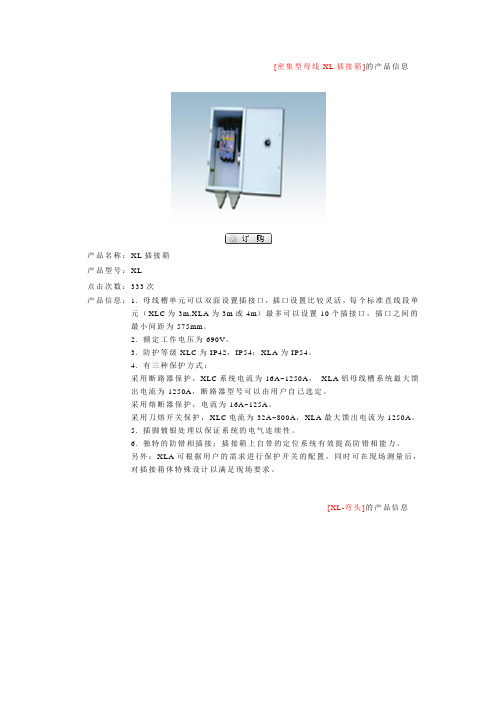
[密集型母线XL插接箱]的产品信息产品名称:X L插接箱产品型号:X L点击次数:333次产品信息:1. 母线槽单元可以双面设置插接口,插口设置比较灵活,每个标准直线段单元(XLC为3m,XLA为3m或4m)最多可以设置10个插接口,插口之间的最小间距为575mm。
2. 额定工作电压为690V。
3. 防护等级XLC为IP42,IP54;XLA为IP54。
4. 有三种保护方式:采用断路器保护,XLC系统电流为16A~1250A,XLA铝母线槽系统最大馈出电流为1250A,断路器型号可以由用户自己选定。
采用熔断器保护,电流为16A~125A。
采用刀熔开关保护,XLC电流为32A~800A,XLA最大馈出电流为1250A。
5. 插脚镀银处理以保证系统的电气连续性。
6. 独特的防错相插接:插接箱上自带的定位系统有效提高防错相能力。
另外:XLA可根据用户的需求进行保护开关的配置,同时可在现场测量后,对插接箱体特殊设计以满足现场要求。
[XL-弯头]的产品信息产品名称:X L-弯头产品型号:点击次数:279次产品信息:X L母线提供模块化设计的L型,T型,十字型,Z型弯头,可以方便的更改母线槽系统的走向,以适应复杂的现场条件,同时外形尺寸小,外观精致,为用户节省空间。
[XL连接器]的产品信息产品名称:X L连接器[XL直线段]的产品信息产品名称:X L直线段产品型号:点击次数:413次产品信息:XLA/XLC密集绝缘型母线槽壳体结构为完全密封型,最高防护等级可达IP65,可在恶劣的环境条件下使用。
系统选择具有大于相线50%容量的整个外壳作接地系统,保证足够的安全性,为接地故障提供可靠的接地路径,为地线短路提供最短的路径。
当发生高容量的接地故障时可有效的接地和保护整个系统。
馈电式母线槽可以垂直安装也可以水平安装。
[空气型母线插接箱]的产品信息产品名称:插接箱产品型号:L D点击次数:79次产品信息:设计有可靠的机械联锁和电气保护,其接地极始终保持先接触后断开,而防护罩能确保操作人员安全。
西门子 建筑电器 说明书

5SX9100 5SX9101 5SX9102 5SX9200 5SX9209 (正面带指示窗口) 5SX9201 5SX9202 5SX9300 5ST3010 5ST3011 5ST3012 5ST3020 5ST3021 5ST3022 5ST3030 5ST3031 5ST3040 5ST3041 5ST3042 5ST3043 5ST3044 5ST3045
6 7 10 11 13
剩余电流保护断路器
电磁式,5SU,AC 型, 额定分断能力至 4.5kA 电磁式,5SU,AC 型, 额定分断能力至 6kA 电子式,5SU9,AC 型, 额定分断能力至 6kA 电磁式,剩余电流保护器 5SM1 隔离开关 5TE7 避雷器和过电压保护器 5SD70 18 19 17 16
额定电流: 0.3~63A 脱扣特性: A, B, C, D 5SP 重载型 (5SP4 分断能力 10kA) 可加附件。 5SP D 80 / 3P 极数: 1P, 2P, 3P, 4P 额定电流: 40~125A 脱扣特性: B, C, D 例如: 5SP D80/3P 即表示: 5SP4 80 安培 3 极开关, D 型脱扣。
请将您的要求寄往与您最近的西门子办事处 Please direct requests to your Siemens branch office 注意 : 技术数据旨在提供一般信息。在安装和维修时必须严格遵守使用说明书以及产品上标识的提示。 Warning: The technical data stated only for general information purposes. When installing, operating or maintaining equipment the operating instructions/Assembly instructions and the information stated on the equipment must be taken into consideration.
母线槽参数及技术要求

母线槽参数及技术要求1、密集型母线槽性能参数和要求1.1母线结构型式:密集母线;电压等级:380V 耐压等级:690V 1.2母线系统:交流TN-C系统1.3防护等级:IP55;额定频率:50HZ;额定绝缘电压:660AC;绝缘电阻:≥20MΩ1.4母线槽至少采用100%相线容量的N线,PE线要求不少于50%相线容量,允许采用铝导体外壳作为接地,但必须是可靠的,截面>50%相线的外壳方式。
1.5母线槽必须保证110%额定电流下长期稳定运行。
1.6电流密度必须不大于2A/MM21.7地线系统采用先进的整体接地地线(地线将相线和中性线全部包裹在内,从而把直接带电部分完全隔离,同时阻断母线周围的磁路,以保证母线槽具有了可靠的接地性能,较小的电抗值,较强的抗谐波能力)。
1.8导体材料1.8.1母线槽A、B、C、N四相导体采用T2电解铜轧制的高导电率TMY电工硬铜排,符合国标,铜排纯度要求≥99.99%,导电率≥98.6%,电抗率≤0.00032Ωmm2/m,硬度HB≥65。
1.8.2铜排表面全长必须镀锡。
1.8.3中性线的材料、截面及制造工艺与相线相同,中性线等效截面应等于100%的相线等效截面。
1.8.4接地导体等效截面应不小于50%的相线等效截面母线接地。
1.9绝缘材料:1.9.1母线绝缘介质选用阻燃材料,绝缘等级及耐热等级达到A级或A级以上,能耐受150℃高温和-60℃的低温,在火灾时不释放有毒气体。
1.9.2绝缘材料采用整体包覆每相铜排的工艺,绝缘老化寿命达到30年以上。
1.9.3在长期处于-5℃~40℃的环境温度下,能保持其柔韧性和介电强度,不会老化。
介电强度≥80KV/mm,抗拉强度>12Mpa。
1.9.4 投标人应提供绝缘材料的所有相关的检测报告。
1.10外壳材料:1.10.1为保证母线槽的强度和刚度及散热效果,母线槽系统外壳侧板采用带散热装置外壳,必须提供相应报告。
1.10.2采用全封闭形式,结构紧凑,配置灵活,动热稳定性好,有较强的抗内外力冲击能力。
母线槽设计规范范文

母线槽设计规范范文母线槽是电力系统中的一种重要电气设备,主要用于电能传输和分配,具有安装方便、造价低廉、维护简单的特点。
为了确保母线槽的正常运行和安全性,制定了一系列的设计规范。
一、设计基础:母线槽设计应遵循相关国家和行业的标准、规范,如《电气安全规范》、《电气设备安装工程施工及验收规范》等。
同时,还应考虑所在建筑物的实际情况、使用要求以及停用电力设备的位置和数量等。
二、母线槽尺寸和材质:尺寸的选择应根据所需电流载荷、环境温度、线路数量等来确定。
而材质的选择则应考虑到使用环境的耐腐蚀性能、耐热性能等。
三、接地:母线槽必须进行可靠接地,接地电阻应符合国家相关规定。
同时,应在设计过程中考虑到接地电阻的测量和维护。
四、导体的接触电阻:导体的接触电阻是母线槽中一个重要的性能指标。
设计应采取合理的导体接触方式和接触面积,以保证低接触电阻。
五、通风和散热:为了确保母线槽的正常运行,应采取通风和散热措施。
这可以通过加装风扇或通风口等方式来实现。
六、防腐蚀:母线槽的外表面和内表面都要做好防腐蚀处理。
一般采用金属防腐涂料或不锈钢材料来保护。
七、绝缘材料:绝缘材料的选择应符合国家相关标准。
在设计过程中,应选择具有良好绝缘性能的材料,以保证线路的安全运行。
八、分段连接:母线槽应根据母线的长度和容量进行合理的分段连接,以便于维护和扩充。
九、安全距离:母线槽的设计应考虑到电弧故障的可能性,采取合适的措施来保护人身安全。
母线槽与周围设备的安全距离应符合国家相关标准。
十、操作空间:为了方便运维人员对母线槽进行维护和检修,应提供充足的操作空间。
同时,还应通过合适的标识和警示标志,提醒人员注意安全。
以上是关于母线槽设计规范的一些要点,设计过程中还应根据具体情况考虑其它因素,如可靠性、经济性、可维护性等。
最终的设计方案应满足安全、可靠、经济、合理的要求,以确保母线槽能够正常运行。
西门子产品数据手册 - 建筑产品说明书
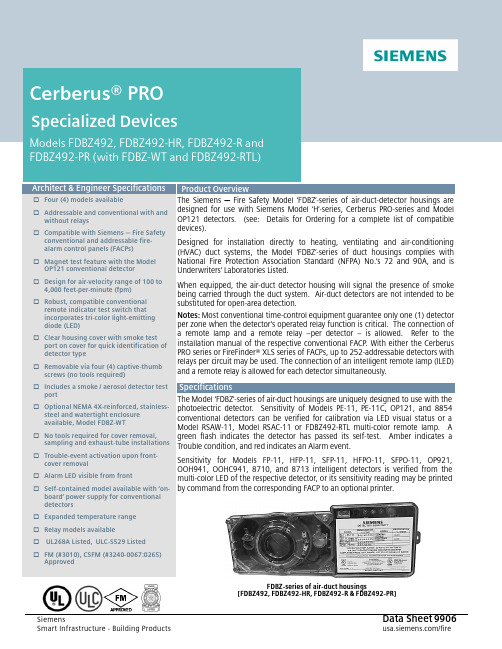
FDBZ-series of air-duct housings☐ Four (4) models available ☐ Addressable and conventional with and without relays☐ Compatible with Siemens ─ Fire Safetyconventional and addressable fire-alarm control panels (FACPs) ☐ Magnet test feature with the ModelOP121 conventional detector ☐ Design for air-velocity range of 100 to4,000 feet-per-minute (fpm) ☐ Robust, compatible conventionalremote indicator test switch that incorporates tri-color light-emitting diode (LED) ☐ Clear housing cover with smoke testport on cover for quick identification of detector type☐ Removable via four (4) captive-thumbscrews (no tools required)☐ Includes a smoke / aerosol detector test port☐ Optional NEMA 4X-reinforced, stainless-steel and watertight enclosureavailable, Model FDBZ-WT☐ No tools required for cover removal, sampling and exhaust-tube installations ☐ Trouble-event activation upon front-cover removal☐ Alarm LED visible from front ☐ Self-contained model available with ‘on-board’ power supply for conventional detectors☐ Expanded temperature range ☐ Relay models available☐ UL268A Listed, ULC-S529 Listed ☐ FM (#3010), CSFM (#3240-0067:0265) ApprovedThe Siemens ─ Fire Safety M odel ‘FDBZ’-series of air-duct-detector housings are designed for use with Siemens M odel ‘H’-series, Cerberus PRO-series and M odelOP121 detectors. (see: Details for Ordering for a complete list of compatible devices).Designed for installation directly to heating, ventilating and air-conditioning (HVAC) duct systems, the M odel ‘FDBZ’-series of duct housings complies with National Fire Protection Association Standard (NFPA) No.’s 72 and 90A, and is Underwriters’ Laboratories Listed.When equipped, the air-duct detector housing will signal the presence of smoke being carried through the duct system. Air-duct detectors are not intended to be substituted for open-area detection.Notes: Most conventional time-control equipment guarantee only one (1) detector per zone when the detector’s operated relay function is critical. The connection of a remote lamp and a remote relay −per detector − is allowed. Refer to the installation manual of the respective conventional FACP. With either the Cerberus PRO series or FireFinder® XLS series of FACPs, up to 252-addressable detectors with relays per circuit may be used. The connection of an intelligent remote lamp (ILED) and a remote relay is allowed for each detector simultaneously.The Model ‘FDBZ’-series of air-duct housings are uniquely designed to use with thephotoelectric detector. Sensitivity of M odels PE-11, PE-11C, OP121, and 8854 conventional detectors can be verified for calibration via LED visual status or aM odel RSAW-11, M odel RSAC-11 or FDBZ492-RTL multi-color remote lamp. Agreen flash indicates the detector has passed its self-test. Amber indicates a Trouble condition, and red indicates an Alarm event.Sensitivity for M odels FP-11, HFP-11, SFP-11, HFPO-11, SFPO-11, OP921, OOH941, OOHC941, 8710, and 8713 intelligent detectors is verified from themulti-color LED of the respective detector, or its sensitivity reading may be printed by command from the corresponding FACP to an optional printer.The remote alarm indicator (Model FDBZ492-RTL) allows for manual testing via a key-switch for conventional and addressable detectors, as well as the conventional and addressable air-duct housing with relay. Model FDBZ492-RTL, which mounts remotely from the conventional and addressable air-duct housing, allows for manual relay-output control. The duct-detector remote indicator key-switch also indicates the current state of the detector.The watertight housing (Model FDBZ-WT), which allows the air-duct detector housing to be installed inside the separate NEMA 4X enclosure, is for installations for either an outdoor area or in environments where excessive moisture is prevalent.Each detector unit employs a cross-sectional sampling principle of operation. Inlet sampling tubes areavailable in four (4) lengths (see: Sampling Tube Selection Table). Outlet sampling tubes are one (1) common length and draw. A continuous, cross-sectional sample of air moves through the duct. Stratification or skin affect phenomenon that occurs in the duct can prevent smoke (especially in large ducts) from reaching a spot-type detector.In addition, the unique design of the sampling chamber ensures uniform sensitivity in air velocities, ranging from a low of 100 fpm to as high as 4,000 fpm. Each air-duct housing comes with three (3) wiring entry ports:▪Two (2) 3/4” conduit knockouts▪One (1) 1/2” conduit openingThe inlet sampling tube length is determined by the width of the air duct being protected. The inlet tube ─ greater than and nearest to the duct width ─ should be used (see: Sampling Tube Selection Table). The inlet tube can then be trimmed at the job site to the exact width of the duct. The outlet sampling tube for all ducts ─ irrespective of width ─ has a fixed length of approximately 5.5 inches (14cm.), and is supplied with the air-duct housing.Note: When the use of a remote relay is required, order Model FDBZ492-R for conventional systems; Model FDBZ492-HR for addressable systems. When required, a separate watertight enclosure (Model FDBZ-WT), which is designed to contain the air-duct housings is available.(For full details, refer to installation instructions for the respective air-duct housing.)Note: When a self-contained duct detector with power supply is required, order Model FDBZ492-PR.(For full details, refer to installation instructions - part number A6V10330327.)Sampling Tube Selection TableDuct Width Sampling Tube(Model No.)For duct widths 6” to 1’ ST-10For duct widths 1’ to 3’ ST-25For duct widths 3’ to 5’(requires support) ST-50For duct widths 5’ to 10’(requires support) ST-100Maintenance of the detector is easily accomplished via the removal of the duct-housing sampling chamber cover. The detector, which plugs into the housing, is easily removed for cleaning or replacing by a trained technician.All that is necessary for installation of the air-duct detector is the cutting of three (3) small holes for the Sampling Tube installation (template included), and the drilling of two (2) holes for mounting the air-duct housing. The unit is then easily mounted in place, and connection made to the existing wires or terminals ─ if optional accessories are utilized. No mechanical tools are required for removing the cover or connecting the sampling and exhaust tubes to an air-duct housing.Models ST-50 and ST-100 require support. However, Model ST-100 is shipped in two (2) 5-ft. (152 cm.) pieces with a coupling for field assembly.Based on the monitoring results, the LED indicator flashes the following colors based on the following conditions:*LED can be turned OFF.Please follow the corresponding description of the panel used.Flash Color ConditionFlash Interval (in seconds) Green*: Normal supervisory operation. Smoke sensitivity is withinrated limits. 10 Yellow: Detector is in Trouble condition, and needs either repair or replacement.4 Red: Alarm condition. 1No Flash: Detector is not powered. ─ ─Operating TemperatureRanges: +32°F (0°C) to 120°F (49°C)Sampling Tube Pressure Range of Differences: > 0.01 inches - < 1.2 inches ofwater column Relative Humidity: 0 - 95%; non-condensingAir Pressure: No effect Altitude Range:No limitations Air-Duct Velocity:100 ─ 4,000 ft. / min (0.51─ 20m / sec)Dimensions: (H -x- W -x- D)Rectangular: 14.38” -x- 5” -x- 2.5”(37 cm. -x- 12.7 cm. -x- 6.36 cm.)Square: 7.75” -x- 9” -x- 2.5”(19.7 cm. -x- 22.9 cm. -x- 6.36 cm.)Detector Weight:1.8 Lbs. (0.82 Kg.)▪ Short-Return (outlet) Tube ▪ Stopper▪#12 + 3/4” Sheet -Metal Screws ▪Mounting TemplateNote: Detector and Sampling Tube to be purchased separately. Minimum hardware required:− one (1) Air-Duct Housing Assembly − one (1) Sampling Tube − one (1) DetectorN OT I CE – The information contained in this data-sheet document is intended only as a summary, and is subject to change without notice.The product(s) described here ha s/hav e a specific instruction sheet(s)that cover various technical, limitation and liability information.Copies of install-type, instruction sheets – as well as the General Product Warning and Limitations document, which also contains important data, are provided with the product, and are available from the Manufacturer. Data contained in the aforesaid type of documentation should be consulted with a fire-safety professional before specifying or using the product. Any further questions or assistance concerning particular problems that might arise, relative to the proper functioning of the equipment, please contact the Manufacturer.Cerberus PRO ®Siemens Industry, Inc.Smart Infrastructure - Building Products 2 Gatehall Drive • Parsippany, NJ 07054Tel: (973) 593-2600March - 2023(Rev. 6)。