DCRS-7600E系列交换机安装手册
Dell EqualLogic FS7600 系列设备 安装和设置指南说明书
Dell EqualLogic FS7600 系列设备安装和设置指南管制型号系列 E02T© 版权所有 2011-2013 Dell Inc. 保留所有权利。
Dell™ 和 EqualLogic® 是 Dell Inc. 的商标。
本文使用的所有商标和注册商标均属其各自所有者的财产。
本说明文件中的信息如有更改,恕不另行通知。
未经 Dell 书面许可,严禁以任何形式进行复制。
发布时间:2013 年 10 月部件号:M1T05-ZH-CN A01目录前言v1 开始之前1EqualLogic 简介 FS76001入门步骤3预安装任务3安全建议3硬件保护4使用防静电腕带4环境要求4技术规格4包装箱内物品6未提供的所需硬件6机架要求7交换机要求7所需工具72 硬件机架安装9设备前面板和背面板9将安装滑轨装入机架的安装原则10将设备安装到机架中的步骤10将滑轨连接到机架11将设备固定至机架12连接挡板133 电源连接15将设备连接至电源154 网络电缆连接17网络配置概览17网络接口端口17网络连接要求和建议18连接网络电缆的步骤19连接客户端网络电缆205 NAS 群集配置21配置 NAS 群集的步骤21收集 NAS 群集配置信息21 NAS 群集网络要求和建议操作22客户端网络22 SAN 网络23内部网络23 NAS 配置参考表格23查找控制器并配置 NAS 群集246 NAS 存储分配25分配 NAS 存储区的步骤25收集 NAS 容器信息25创建 NAS 容器26安全与权限26转移共享所有权27访问 CIFS 共享27访问 NFS 导出277 下一步操作29NAS 群集文档29 NAS 群集操作29 NAS 容器操作30词汇表31索引33iiiDell EqualLogic FS7600安装和设置指南目录iv前言Dell™ EqualLogic® FS Series 设备与 PS Series 阵列相结合,提供高性能、高可用性、可扩展的 NAS 解决方案。
CISCO交换机安装手册【板卡】
C H A P T E R2-1Cisco 7600 Series Routers Module GuideOL-9392-032Ethernet and Gigabit Ethernet Switching ModulesThis chapter describes the Ethernet and Gigabit Ethernet switching modules, and it contains these sections:•10/100 and 10/100/1000 Ethernet Switching Modules, page 2-1•Gigabit Ethernet Switching Modules, page 2-13•Ethernet Module LEDs, page 2-2210/100 and 10/100/1000 Ethernet Switching ModulesNoteSpecific combinations of supervisor engines and modules may not be supported in your chassis. Refer to the release notes for the software version running on your system for specific information on modules and supervisor engine combinations that are not supported.This section describes these 10/100 and 10/100/1000 Ethernet switching modules:•24-Port 10BASE-FL Ethernet Switching Module (WS-X6024-10FL-MT), page 2-4•48-Port 10/100/1000BASE-T Ethernet Switching Module (WS-X6148-GE-TX), page 2-4•48-Port 10/100/1000BASE-T Ethernet Switching Module (WS-X6148V-GE-TX), page 2-4•48-Port 10/100BASE-T Ethernet Switching Module (WS-X6148-RJ21V), page 2-5•48-Port 10/100BASE-T Ethernet Switching Module (WS-X6148-RJ45V), page 2-6•24-Port 100BASE-FX Ethernet Switching Module (WS-X6224-100FX-MT), page 2-6•48-Port 10/100BASE-T Ethernet Switching Module (WS-X6248-RJ45), page 2-7•48-Port 10/100BASE-T Ethernet Switching Module (WS-X6248-TEL), page 2-7•48-Port 10/100BASE-T Ethernet Switching Module (WS-X6248A-TEL), page 2-7•24-Port 100BASE-FX Ethernet Switching Module (WS-X6324-100FX-MM), page 2-8•24-Port 100BASE-FX Ethernet Switching Module (WS-X6324-100FX-SM), page 2-8•48-Port 10/100BASE-T Ethernet Switching Module (WS-X6348-RJ21V), page 2-9•48-Port 10/100BASE-T Ethernet Switching Module (WS-X6348-RJ-45), page 2-9•48-Port 10/100BASE-T Ethernet Switching Module (WS-X6348-RJ45V), page 2-10Cisco 7600 Series Routers Module GuideOL-9392-03Chapter 2 Ethernet and Gigabit Ethernet Switching Modules10/100 and 10/100/1000 Ethernet Switching Modules•24-Port 100BASE-FX Fabric-Enabled Ethernet Switching Module (WS-X6524-100FX-MM), page 2-10•48-Port 10/100/1000BASE-T Ethernet Switching Module (WS-X6548-GE-TX), page 2-11•48-Port 10/100/1000BASE-T Ethernet Switching Module (WS-X6548V-GE-TX), page 2-11•48-Port 10/100BASE-T Fabric-Enabled Ethernet Switching Module (WS-X6548-RJ-21), page 2-12•48-Port 10/100BASE-T Fabric-Enabled Ethernet Switching Module (WS-X6548-RJ-45), page 2-12•48-Port 10/100/1000BASE-T Fabric-Enabled Ethernet Switching Module (WS-X6748-GE-TX), page 2-13Table 2-1 lists the features of the Ethernet switching modules.T able 2-1Ethernet Switching Modules FeaturesProduct Number Backplane Connection Forwarding Inline Power 1Port Buffer Size Queues Per Port WS-X6024-10FL-MT 32 Gbps Bus Centralized No 128 KB 2 transmit,1 receive WS-X6148-GE-TX 32 Gbps Bus Centralized Optional 2128 KB 2 transmit,1 receive WS-6148V-GE-TX 32 Gbps Bus Centralized Yes 128 KB 2 transmit,1 receive WS-X6148-RJ21V 32 Gbps Bus Centralized Yes 128 KB 2 transmit,1 receive WS-X6148-RJ45V 32 Gbps Bus Centralized Yes 128 KB 2 transmit,1 receive WS-X6224-100FX-MT 32 Gbps Bus Centralized Yes 128 KB 2 transmit,1 receive WS-X6248-RJ-4532 Gbps Bus Centralized No 128 KB 2 transmit,1 receive WS-X6248-TEL 32 Gbps Bus Centralized No 128 KB 2 transmit,1 receive WS-X6248A-TEL 32 Gbps Bus Centralized No 128 KB 2 transmit,1 receive WS-X6324-100FX-MM 32 Gbps Bus Centralized No 128 KB 2 transmit,1 receive WS-X6324-100FX-SM 32 Gbps Bus Centralized No 128 KB 2 transmit,1 receive WS-X6348-RJ21V 32 Gbps Bus Centralized Yes 128 KB 2 transmit,1 receive WS-X6348-RJ-4532 Gbps Bus Centralized Optional 2128 KB 2 transmit,1 receive WS-X6348-RJ45V32 Gbps BusCentralizedYes128 KB2 transmit,1 receiveCisco 7600 Series Routers Module GuideOL-9392-03Chapter 2 Ethernet and Gigabit Ethernet Switching Modules10/100 and 10/100/1000 Ethernet Switching ModulesWS-X6524-100FX-MMSwitch Fabric and BusCentralized Supportsoptional DFC card No1 MB4 transmit,2 receiveWS-X6548-GE-TX Switch Fabric and Bus Centralized Optional 2 1 MB 4 transmit,2 receive WS-6548V-GE-TX Switch Fabric and Bus Centralized Yes 1 MB 4 transmit,2 receive WS-X6548-RJ-21Switch Fabric and BusCentralized Supportsoptional DFC card No1 MB4 transmit,2 receiveWS-X6548-RJ-45Switch Fabric and BusCentralized Supportsoptional DFC card No 1 MB4 transmit,2 receiveWS-X6748-GE-TXSwitch Fabric CEF720No 1.3 MB4 transmit,2 receive1.Supports IP phones.2.Supports an optional inline power field upgrade module (WS-F6K-VPWR=)T able 2-1Ethernet Switching Modules Features (continued)Product Number Backplane Connection Forwarding Inline Power 1Port Buffer Size Queues Per Port2-4Cisco 7600 Series Routers Module GuideOL-9392-03Chapter 2 Ethernet and Gigabit Ethernet Switching Modules10/100 and 10/100/1000 Ethernet Switching ModulesNote2-5Cisco 7600 Series Routers Module GuideOL-9392-03Chapter 2 Ethernet and Gigabit Ethernet Switching Modules10/100 and 10/100/1000 Ethernet Switching Modules2-6Cisco 7600 Series Routers Module GuideOL-9392-03Chapter 2 Ethernet and Gigabit Ethernet Switching Modules10/100 and 10/100/1000 Ethernet Switching ModulesNote2-7Cisco 7600 Series Routers Module GuideOL-9392-03Chapter 2 Ethernet and Gigabit Ethernet Switching Modules10/100 and 10/100/1000 Ethernet Switching Modules2-8Cisco 7600 Series Routers Module GuideOL-9392-03Chapter 2 Ethernet and Gigabit Ethernet Switching Modules10/100 and 10/100/1000 Ethernet Switching ModulesNoteNote2-9Cisco 7600 Series Routers Module GuideOL-9392-03Chapter 2 Ethernet and Gigabit Ethernet Switching Modules10/100 and 10/100/1000 Ethernet Switching Modules2-10Cisco 7600 Series Routers Module GuideOL-9392-03Chapter 2 Ethernet and Gigabit Ethernet Switching Modules10/100 and 10/100/1000 Ethernet Switching ModulesNote2-11Cisco 7600 Series Routers Module GuideOL-9392-0310/100 and 10/100/1000 Ethernet Switching Modules2-12Cisco 7600 Series Routers Module GuideOL-9392-0310/100 and 10/100/1000 Ethernet Switching Modules2-13Cisco 7600 Series Routers Module GuideOL-9392-03Gigabit Ethernet Switching ModulesCisco 7600 Series Routers Module GuideOL-9392-03Gigabit Ethernet Switching ModulesT able 2-2Gigabit and 10-Gigabit Ethernet Switching Modules FeaturesProduct Number Backplane Connection Forwarding Number of Transmit Queues/Port Number of Receive Queues/Port WS-X6316-GE-TX Bus Centralized 32WS-X6408-GBIC Bus Centralized 32WS-X6408A-GBIC Bus Centralized 32WS-X6416-GBIC Bus Centralized 32WS-X6416-GE-MT BusCentralized32WS-X6501-10GEX4Switch fabric and busCentralized. Support for distributed forwarding with optionaldistributed forwarding card (DFC)32WS-X6502 -10GESwitch fabric and bus Centralized. Support for distributed forwarding with optional DFC 32WS-X6516-GBIC Switch fabric and bus Centralized. Support for distributed forwarding with optional DFC 32WS-X6516A-GBIC Switch fabric and bus Centralized. Support for distributed forwarding with optional DFC 32WS-X6516-GE-TX Switch fabric and busCentralized. Support for distributed forwarding with optional DFC32WS-X6704-10GESwitch fabric 1(dual channel)1.The module can be installed in slots 2–6 in the Cisco 7606, slots 2–9 in the Cisco 7609 and OSR-7609, and slots 9–13 in the Cisco7613 routers. It cannot be installed in slots 2–8 of the Cisco 7613 router. The module requires a Supervisor Engine 720.Centralized. Support for distributed forwardingwith optional DFC 3222.Receive queues change depending on whether you have a centralized forward card (CFC) or a DFC. For information about queuestructures, see /en/US/docs/routers/7600/ios/12.2SXF/configuration/guide/qos.html#wp1666010.WS-X6724-SFPSwitch fabricCentralized. Support for distributed forwarding with optional DFC 322WS-X6748-SFP Switch fabricCentralized. Support for distributed forwarding with optional DFC322WS-X6816-GBIC Switch fabric 1 (dual channel)Distributed forwarding with integrated DFC 32WS-X6708-10G-3C Switch fabric Distributed forwarding with integrated DFC 882WS-X6708-10G-3CXLSwitch fabricDistributed forwarding with integrated DFC8822-15Cisco 7600 Series Routers Module GuideOL-9392-03Gigabit Ethernet Switching ModulesNoteNote2-16Cisco 7600 Series Routers Module GuideOL-9392-03Gigabit Ethernet Switching ModulesNoteNote2-17Cisco 7600 Series Routers Module GuideOL-9392-03Gigabit Ethernet Switching Modules2-18Cisco 7600 Series Routers Module GuideOL-9392-03Gigabit Ethernet Switching ModulesNoteNote2-19Cisco 7600 Series Routers Module GuideOL-9392-03Gigabit Ethernet Switching Modules2-20Cisco 7600 Series Routers Module GuideOL-9392-03Gigabit Ethernet Switching ModulesNoteNote2-21Cisco 7600 Series Routers Module Guide OL-9392-03Gigabit Ethernet Switching Modules2-22Cisco 7600 Series Routers Module Guide OL-9392-03Ethernet Module LEDsCisco 7600 Series Routers Module Guide OL-9392-03Ethernet Module LEDs LINK GreenThe port is active (the link is connected and operational).OrangeThe module or port is disabled through the CLI command or the module is initializing 1. FlashingorangeThe port is faulty and has been disabled.Off The port is not active or the link is not connected.PHONE Green The voice daughter card is installed.OffThe voice daughter card is not detected or is not installed.1.This is a good time to verify that all LINK LEDs are functioning.T able 2-3Ethernet and Gigabit Ethernet Module LEDs (continued)LEDColor/State DescriptionEthernet Module LEDsCisco 7600 Series Routers Module GuideOL-9392-03。
DCRS-6800E系列交换机安装手册(6804E产品光盘)
1.2 技术指标
项目 插槽 4 10/100/1000BASE-T最多192个 1000Base-SX最多192个 端口 1000Base-LX最多192个 10/100BASE-T最多192个 万兆最多32个 DCRS-6804E 10 10/100/1000BASE-T最多384个 1000Base-SX最多384个 1000Base-LX最多384个 10/100BASE-T最多384个 万兆最多64个 DCRS-6808E
1.5 系统特性 ........................................................பைடு நூலகம்...............................1-53
1.5.1 DCRS-6804E的系统特性 ...................................................................... 1-53 1.5.2 DCRS-6808E的系统特性 ...................................................................... 1-54
1.2 技术指标 ..........................................................................................1-2 1.3 物理特性 ..........................................................................................1-5 1.4 硬件组成 ..........................................................................................1-6
DCRS-7500安装手册(un)

DCRS-7500系列路由交换机安装手册神州数码(上海)网络有限公司前言DCRS-7500系列核心路由交换机是神州数码(上海)网络有限公司推出的机箱式千兆多层交换机产品。
为了帮助用户更好的安装、调试DCRS-7500系列核心路由交换机,我们特编写了本手册。
目录第1章安装准备 (1)1.1打开包装 (1)1.2安装前注意事项 (1)1.2.1环境要求 (1)1.2.2搬运要求 (1)1.2.3电源要求 (1)第2章安装模块 (2)2.1安装和取出模块 (2)2.1.1安装模块 (2)2.1.2取出模块 (2)2.1.3模块热插拔 (2)2.2安装和取出电源模块 (4)2.2.1确定电源状态 (4)2.2.2安装电源模块 (4)2.2.3取出电源模块 (5)2.3检测运行状态 (5)2.4交换机在机架上安装 (5)2.5安装GBIC模块 (6)2.5.1安装标准GBIC (6)2.5.2取出标准GBIC (6)2.5.3安装mini-GBIC (7)2.5.4取出mini-GBIC (7)第3章安装三层功能许可 (8)3.1概览 (8)3.2安装步骤 (8)第4章系统参数 (11)本章讲述了神州数码DCRS-7500系列核心路由交换机在安装前所要做的准备工作。
1.1 打开包装包装中包含下列物品:DCRS-7500系列核心路由交换机1台电源线1根配置线1条机箱安装配件1套手册光盘1张产品保修卡1张产品合格证1张1.2 安装前注意事项1.2.1 环境要求电源、机柜必须有良好的接地提供符合规格要求的电源工作环境温度必须低于40摄氏度确认交换机的前、后、侧面的通风口处没有堵塞确认交换机所有未安装模块的空插槽都有挡板遮护1.2.2 搬运要求抬起交换机时不要使用电源上的把手抬起15插槽交换机时,除非是空机箱,否则不要使用机箱上的把手确认机架能够承受交换机的重量交换机在机架上安装时,较重的设备应尽量放置在机架下部1.2.3 电源要求至少使用两组不同的电源,以便在一组失效时提供冗余确认电源有良好接地确认电源提供足够功率2.1 安装和取出模块2.1.1 安装模块按下列方式安装模块:1. 带上防静电手镯,防静电手镯必须良好接地2. 将机箱上要安装模块插槽的挡板移除,把挡板存放于其他地方备用3. 将模块从包装中取出4. 将模块插入插槽,沿导轨推入,直到模块前方两侧的弹出扳手接触到机箱5. 向模块中央方向压下弹出扳手直到与模块前端平齐6. 拧紧模块两端的螺丝图2.1:安装模块2.1.2 取出模块按下列方式取出模块:1. 带上防静电手镯,防静电手镯必须良好接地2. 松开模块两端的螺丝3. 朝模块两侧方向往外拉弹出扳手,使模块脱离备板4. 将模块从插槽中拉出,放入防静电袋中保存5. 用挡板遮护空插槽2.1.3 模块热插拔神州数码DCRS-7500系列核心路由交换机支持模块的热插拔,但要按照下面说明操作。
美科星通信交换机安装指南说明书

物品清单:一台交换机一个电源适配器一个光盘一本快速安装指南产品介绍快速安装指南全千兆智能网管交换机硬件连接背面示意图正面示意图Copyright © 2018 深圳市美科星通信技术有限公司声明深圳市美科星通信技术有限公司明确书面许可,任何单位或个人不得擅自仿制、复制、誊抄或转译本手册部分或全部内容,且不 为深圳市美科星通信技术有限公司注册商标。
本手册提及的所有商标,由各自所有人拥有。
本手册所提到的产品规格和资讯仅供参考,如有内容更新,恕不另行通知。
除非有特殊约定,本手册仅作为使用指导,所作陈述均不构成任何形式的担保。
技术支持热线400-8810-500公司网址深圳市美科星通信技术有限公司地址:深圳市南山区高新区高新南四道023号高新工业村R1号B区第三层西段7108501982 REV1.0.1本指南所涉及的产品均以SG105 Pro为例,不同型号产品外观可能存在差异,但安装配置过程均相同。
2四个脚垫(仅SG108 Pro有)熄灭:系统未通电或供电异常1.雷雨天气请将设备电源及所有连线拆除,以免遭雷击破坏。
2.远离热源,保持通风。
3.在储存、运输和运行环境中,请注意防水。
4.使用设备额定电源适配器。
5.将设备放置在水平平坦的表面。
6.请将设备安装在电源插座附近,并确保可随时方便地拔掉插头以断电。
7.使用过程中,请保持交换机底部朝下水平放置,避免潜在的安全隐患。
8.此为A级产品,在生活环境中,该产品可能会造成无线电干扰。
在这种情况下,可能需要用户对干扰采取切实可行的措施。
登录Web管理界面1打开浏览器(以IE浏览器为例,建议使用IE8.0以上版本),在地址栏中输入交换机默认管理地址http://192.168.0.1,按下回车键。
交换机登录界面如下图所示,在此界面输入交换机管理账号的用户名和密码,出厂默认值均为admin。
3经过上述步骤即可成功登录交换机Web管理界面,如下图所示。
点击主页左侧的主菜单栏即可进行相应功能的配置。
SIM7600E -H 4G HAT 用户手册说明书
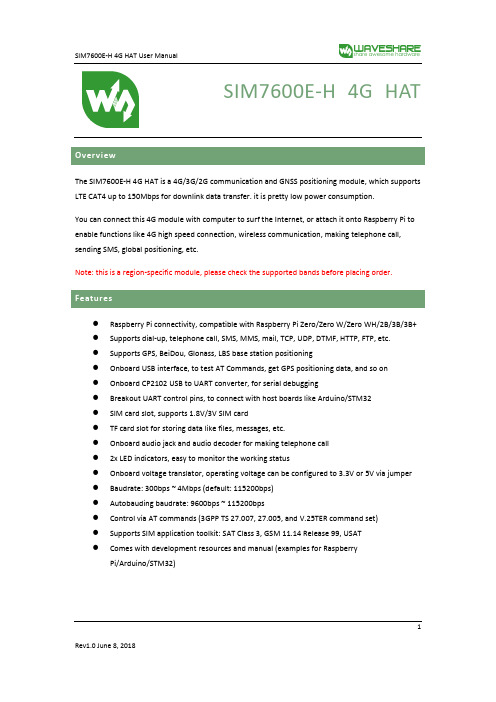
SIM7600E-H 4G HATThe SIM7600E-H 4G HAT is a 4G/3G/2G communication and GNSS positioning module, which supports LTE CAT4 up to 150Mbps for downlink data transfer. it is pretty low power consumption.You can connect this 4G module with computer to surf the Internet, or attach it onto Raspberry Pi to enable functions like 4G high speed connection, wireless communication, making telephone call, sending SMS, global positioning, etc.Note: this is a region-specific module, please check the supported bands before placing order.⚫Raspberry Pi connectivity, compatible with Raspberry Pi Zero/Zero W/Zero WH/2B/3B/3B+ ⚫Supports dial-up, telephone call, SMS, MMS, mail, TCP, UDP, DTMF, HTTP, FTP, etc.⚫Supports GPS, BeiDou, Glonass, LBS base station positioning⚫Onboard USB interface, to test AT Commands, get GPS positioning data, and so on⚫Onboard CP2102 USB to UART converter, for serial debugging⚫Breakout UART control pins, to connect with host boards like Arduino/STM32⚫SIM card slot, supports 1.8V/3V SIM card⚫TF card slot for storing data like files, messages, etc.⚫Onboard audio jack and audio decoder for making telephone call⚫2x LED indicators, easy to monitor the working status⚫Onboard voltage translator, operating voltage can be configured to 3.3V or 5V via jumper ⚫Baudrate: 300bps ~ 4Mbps (default: 115200bps)⚫Autobauding baudrate: 9600bps ~ 115200bps⚫Control via AT commands (3GPP TS 27.007, 27.005, and V.25TER command set)⚫Supports SIM application toolkit: SAT Class 3, GSM 11.14 Release 99, USAT⚫Comes with development resources and manual (examples for RaspberryPi/Arduino/STM32)1Note: Does not contain Raspberry PiCommunications SpecificationsGNSS Specifications⚫Receiver type◼16-channel◼C/A code2⚫Sensitivity◼Tracking: -159 dBm (GPS) / -158 dBm (GLONASS) / TBD (BD)◼Cold starts: -148 dBm⚫Time-To-First-Fix (open air)◼Cold starts: <35s◼Hot starts: <1s⚫Accuracy◼Position: <2.5m CEP⚫SMS◼Supported types: MT, MO, CB, Text, PDU◼Storage: USIM card and ME (default)⚫Audio feature◼Supports echo cancellation◼Supports noise reduction⚫Power supply: 5V⚫Operating voltage: 5V/3.3V (configured via jumper)⚫Operating temperature: -30°C ~ 80°C⚫Storage temperature: -45°C ~ 90°C⚫Dimension: 56.21mm x 65.15mm31.SIM7600E-H2.CP2102 USB to UART converter3.NAU8810 audio decoder4.TXS0108EPWR voltage translator: translates 3.3V/5V into 1.8V5.MP2128DT power chip6.MP1482 power chip7.Raspberry Pi GPIO header: for connecting with Raspberry Pi8.SIM7600 control interface: for connecting with host boards like Arduino/STM329.SIM card slot: supports 1.8V/3V SIM card10.TF card slot: allows file/SMS/... storage11. 3.5mm earphone/mic jackB interface: for testing AT Commands, getting GPS positioning data, etc.B to UART interface: for serial debugging, or login to Raspberry Pi14.MAIN antenna connector15.AUX antenna connector16.GNSS antenna connector17.Power switchwork status indicator19.Power indicator20.Operating voltage selection jumper:VCCIO - 3.3V: set operating voltage as 3.3VVCCIO - 5V: set operating voltage as 5V421.UART selection jumper:A: access Raspberry Pi via USB to UARTB: control the SIM7600 by Raspberry PiC: control the SIM7600 via USB to UART5Overview (1)Features (1)Communications Specifications (2)GNSS Specifications (2)SMS and Audio Specifications (3)Other Specifications (3)What's on Board (3)1.Hardware configuration (8)1.1.Hardware configuration (8)2.At Test Instructions (9)2.1.General AT commands (9)2.2.Make calls and answer calls (10)2.3.Send and receive messages (11)2.4.GPS Debugging (13)2.5.TF Card Test (15)2.6.GPRS Debugging (16)Local virtual severs settings (16)GPRS Test (17)ing with Raspberry Pi (18)3.1.Interface overview (18)3.2.UART configuration of Raspberry Pi (18)3.3.Init the Raspberry Pi (19)63.4.Minicom for UART debugging on Raspberry Pi (20)3.5.Examples (21)3.5.1.PhoneCall (21)3.5.2.SMS (22)3.5.3.GPS (22)3.5.4.TCP (23)3.5.5.FTP (23)ing with Arduino (24)4.1.Interface overview (24)4.2.Install Arduino Library (24)4.2.1.Phonecall (25)4.2.2.SMS (25)4.2.3.GPS (26)4.2.4.TCP (27)4.2.5.FTP (27)71.1.1.Hardware configurationThis module comes with GSM antenna, LTE antenna and micro USB cable. Besides these you should prepare a 4G sim card and a microphone cable with microphone:1)Insert the SIM card to the card slot, Insert the headphone cable and connect the LTE antenna.2)Connect the USB interface of SIM7600E-H 4G HAT to PC with a micro USB cable. Then the PWRindicator will keep bright.3)Press the PWRKEY button and hold for 1s, the NET indicator will blink as below. Generally, theNET indicator will fast flash firstly (1 time per second), which means that the module has not logged in the Network. After logging in, the indicator become to flash slowly (1 time every three seconds). Up to the local LTE network, this process that logging in will last several seconds to dozens of seconds.\If you take too much time to log in and failed, please check that whether the LTE antenna isconnected correctly, and whether the SIM card is usable and insert correctly.4)Install SIM7600 driver (windows driver: /wiki/File:SIM7X00-Driver.7z)Open Device Manager to get the corresponding COM port number of SIM7600. For example, the AT Port is COM19 as below. Users need to choose the correct port according to the Manager.Figure: Devices Manager82.At Test Instructions2.1.General AT commands910For more details, please refer to the documentation :Series_AT Command Manual_V1.072.2. Make calls and answer calls1) Insert the SIM card, connect the LTE antenna and connect the USB interface of SIM7600E-H 4G HAT to PC . Then press the PWRKEY to power on the board;2) Check whether the indicators blink correct ly (PWR’s and NET’s flashes).3)Send AT commands as bellow:ATA Call answer OK2.3.Send and receive messages1.Plug the SIM card, connect the LTE antenna and and c onnect the USB interface ofSIM7600E-H 4G HAT to PC. Then press the PWRKEY to power on the board;2.Check whether the indicators blink correct ly (PWR’s and NET’s flashes).3.Send AT commands as bellow:11122.4.GPS Debugging1)Connecting the GPS antenna, and place the receiver on open area outdoor2)AT+CGPS =1 //Turn on power of GPS3)Open u-center and set the Port and Baudrate (NMEA Port,COM27)4)AT+CGNSINF // Print the GPS information5)AT+CGPS =0 //Turn off power of GPS13142.5.TF Card Test1.Plug the SIM card, connect the LTE antenna and and c onnect the USB interface ofSIM7600E-H 4G HAT to PC. Then press the PWRKEY to power on the board;2.Check whether the indicators blink correct ly (PWR’s and NET’s flashes).3.Send AT commands as bellow:15162.6.GPRS DebuggingVirtual servers define the mapping between service ports of WAN and web servers of LAN. All requests from Internet to service ports of WAN will be redirected to the computer (web servers of LAN) specified by the server IP. (see your router’s guide manual)4)Log in Management Console of your router with browser (read your router’s guide manual forspecific address) 5)Set Port :1822 (The Port can ’t be conflict to other ’s. Here we set 1822)Set LAN IP address of your computer (you can run CMD on your computer, and execute command ipconfig to enquiry the address of IPv4), 192.168.6.168 as examples6)You can search “IP” on browser to get your WAN IP address.1.Plug the SIM card, connect the LTE antenna and and c onnect the USB interface ofSIM7600E-H 4G HAT to PC. Then press the PWRKEY to power on the board;2.Check whether the indicators blink correct ly (PWR’s and NET’s flashes).3.Send AT commands as bellow:17ing with Raspberry Pi3.1.Interface overviewThe default relationship between SIM7600 control pins and Raspberry Pi IOs is shown in Table 1. Table 1: The relationship between SIM7600 control pins and Raspberry Pi IOs3.2.UART configuration of Raspberry PiBecause UART of Raspberry Pi is used for Linux console output by default, if we want to use the UART, we need to change the settings. Executing this command to enter the configuration page :1819Open /boot/config.txt file, find the below statement and uncomment it to enable the UART. You can directly append it at the end of file as well.Then reboot.3.3. Init the Raspberry Pi1、Download the raspberry pi demo code and copy the SIM7600X folder to /home/pi/ directory. 2、 Enter /home/pi/ directory,execute command:3、 Open the /etc/rc.local file, then add the context below:203.4. Minicom for UART debugging on Raspberry PiInserting the module to Raspberry Pi and plug the jumper B,Install minicom ,minicom is a text-based modem control and terminal emulation program for Linux :Execute command:ttyS0 is the UART of Raspberry Pi 3B) Baud rate is 115200 by default. If you need to change the baud rate, for example 9600, you can add the parameter -b 9600.The user UART device of Raspberry Pi 2B/Zero is ttyAMA0, and ttyS0 of Raspberry Pi 3B Testing Bluetooth function as examples:213.5. Examples1、Download the demo code from wiki and copy to the Raspberry Pi (/home/pi/SIM7600X) 2、Enter the bcm2835 directory, compile and install the BCM2835 library:4、 Compile and run the demo (for example:PhoneCall): Clean up: sudo make clean Recompile: sudo makeRun the program: sudo ./PhoneCallCombination command: sudo make clean && sudo make && sudo ./PhoneCall2223ing with Arduino4.1.Interface overviewThe default relationship between SIM7600 control pins and Arduino is shown in Table 1.Table 2: The relationship between SIM7600 control pins and Arduino4.2.Install Arduino Library1.Download the Arduino demo code and copy the Waveshare_SIM7600X_Arduino_Library folderto {the Arduino software installation path}/Library/ .2.Run the Arduino IDE, then select the example code as below:244.2.1.PHONECALL254.2.3.GPS262728。
交换机安装标准手册整理版
交换机安装标准手册一、前言本手册旨在为交换机安装提供标准化的指导和操作规范。
在计算机网络中,交换机扮演着重要的角色,其安装过程的质量直接影响到网络的性能和稳定性。
因此,遵循本手册进行规范的交换机安装至关重要。
二、准备工作1. 确定交换机的安装位置,确保其处于网络的核心位置,并且便于维护和管理。
2. 准备所需的工具和材料,包括螺丝刀、网络钳、网线、电源线等。
3. 仔细阅读交换机的安装说明书,了解其硬件结构和配置要求。
三、安装步骤1. 连接电源线:将电源线连接到交换机的电源接口,确保电源线的紧固和稳定。
2. 连接网线:将网线连接到交换机的LAN口和计算机的网络接口,确保网线的紧固和稳定。
3. 配置交换机:根据网络需求,配置交换机的IP地址、网关、DNS等网络参数。
4. 测试网络连接:通过ping命令或其他网络测试工具,测试计算机与交换机的网络连接是否正常。
5. 记录配置信息:记录交换机的配置信息,包括IP地址、端口配置、安全设置等,以便于后续管理和维护。
四、注意事项1. 在安装过程中,请遵循交换机的品牌和型号,确保正确连接电源线和网线。
2. 请勿在交换机未完全关闭的情况下进行操作,以避免损坏硬件设备。
3. 在配置交换机时,请根据实际需求进行设置,确保网络的稳定性和安全性。
4. 定期检查交换机的运行状态,及时发现并解决潜在的问题。
五、常见问题及解决方案1. 交换机无法正常启动:检查电源是否连接正常,检查网线是否连接正常。
2. 网络连接不稳定:检查网络设置是否正确,检查网线是否老化或损坏。
3. 无法访问交换机管理界面:检查交换机的IP地址和端口设置是否正确,检查浏览器设置是否正确。
4. 交换机出现故障:请联系技术支持或专业人员进行维修和检测。
六、附录1. 本手册中涉及的交换机型号和品牌仅供参考,具体操作请遵循所使用的交换机的说明书。
2. 本手册未涉及到的交换机安装和维护问题,请参考相关的技术文档或联系技术支持获取帮助。
Cisco 7600 Series 路由器模块指南说明书
C H A P T E R2-1Cisco 7600 Series Routers Module GuideOL-9392-042Ethernet and Gigabit Ethernet Switching ModulesThis chapter describes the Ethernet and Gigabit Ethernet switching modules, and it contains these sections:•10/100 and 10/100/1000 Ethernet Switching Modules, page 2-1•Gigabit Ethernet Switching Modules, page 2-13•Ethernet Module LEDs, page 2-2110/100 and 10/100/1000 Ethernet Switching ModulesNoteSpecific combinations of supervisor engines and modules may not be supported in your chassis. Refer to the release notes for the software version running on your system for specific information on modules and supervisor engine combinations that are not supported.This section describes these 10/100 and 10/100/1000 Ethernet switching modules:•24-Port 10BASE-FL Ethernet Switching Module (WS-X6024-10FL-MT), page 2-4•48-Port 10/100/1000BASE-T Ethernet Switching Module (WS-X6148-GE-TX), page 2-4•48-Port 10/100/1000BASE-T Ethernet Switching Module (WS-X6148V-GE-TX), page 2-4•48-Port 10/100BASE-T Ethernet Switching Module (WS-X6148-RJ21V), page 2-5•48-Port 10/100BASE-T Ethernet Switching Module (WS-X6148-RJ45V), page 2-6•24-Port 100BASE-FX Ethernet Switching Module (WS-X6224-100FX-MT), page 2-6•48-Port 10/100BASE-T Ethernet Switching Module (WS-X6248-RJ45), page 2-7•48-Port 10/100BASE-T Ethernet Switching Module (WS-X6248-TEL), page 2-7•48-Port 10/100BASE-T Ethernet Switching Module (WS-X6248A-TEL), page 2-7•24-Port 100BASE-FX Ethernet Switching Module (WS-X6324-100FX-MM), page 2-8•24-Port 100BASE-FX Ethernet Switching Module (WS-X6324-100FX-SM), page 2-8•48-Port 10/100BASE-T Ethernet Switching Module (WS-X6348-RJ21V), page 2-9•48-Port 10/100BASE-T Ethernet Switching Module (WS-X6348-RJ-45), page 2-9•48-Port 10/100BASE-T Ethernet Switching Module (WS-X6348-RJ45V), page 2-10Cisco 7600 Series Routers Module GuideOL-9392-04Chapter 2 Ethernet and Gigabit Ethernet Switching Modules10/100 and 10/100/1000 Ethernet Switching Modules•24-Port 100BASE-FX Fabric-Enabled Ethernet Switching Module (WS-X6524-100FX-MM), page 2-10•48-Port 10/100/1000BASE-T Ethernet Switching Module (WS-X6548-GE-TX), page 2-11•48-Port 10/100/1000BASE-T Ethernet Switching Module (WS-X6548V-GE-TX), page 2-11•48-Port 10/100BASE-T Fabric-Enabled Ethernet Switching Module (WS-X6548-RJ-21), page 2-12•48-Port 10/100BASE-T Fabric-Enabled Ethernet Switching Module (WS-X6548-RJ-45), page 2-12•48-Port 10/100/1000BASE-T Fabric-Enabled Ethernet Switching Module (WS-X6748-GE-TX), page 2-13Table 2-1 lists the features of the Ethernet switching modules.T able 2-1Ethernet Switching Modules FeaturesProduct Number Backplane Connection Forwarding Inline Power 1Port Buffer Size Queues Per Port WS-X6024-10FL-MT 32 Gbps Bus Centralized No 128 KB 2 transmit,1 receive WS-X6148-GE-TX 32 Gbps Bus Centralized Optional 2128 KB 2 transmit,1 receive WS-6148V-GE-TX 32 Gbps Bus Centralized Yes 128 KB 2 transmit,1 receive WS-X6148-RJ21V 32 Gbps Bus Centralized Yes 128 KB 2 transmit,1 receive WS-X6148-RJ45V 32 Gbps Bus Centralized Yes 128 KB 2 transmit,1 receive WS-X6224-100FX-MT 32 Gbps Bus Centralized Yes 128 KB 2 transmit,1 receive WS-X6248-RJ-4532 Gbps Bus Centralized No 128 KB 2 transmit,1 receive WS-X6248-TEL 32 Gbps Bus Centralized No 128 KB 2 transmit,1 receive WS-X6248A-TEL 32 Gbps Bus Centralized No 128 KB 2 transmit,1 receive WS-X6324-100FX-MM 32 Gbps Bus Centralized No 128 KB 2 transmit,1 receive WS-X6324-100FX-SM 32 Gbps Bus Centralized No 128 KB 2 transmit,1 receive WS-X6348-RJ21V 32 Gbps Bus Centralized Yes 128 KB 2 transmit,1 receive WS-X6348-RJ-4532 Gbps Bus Centralized Optional 2128 KB 2 transmit,1 receive WS-X6348-RJ45V32 Gbps BusCentralizedYes128 KB2 transmit,1 receiveCisco 7600 Series Routers Module GuideOL-9392-04Chapter 2 Ethernet and Gigabit Ethernet Switching Modules10/100 and 10/100/1000 Ethernet Switching ModulesWS-X6524-100FX-MMSwitch Fabric and BusCentralized Supportsoptional DFC card No1 MB4 transmit,2 receiveWS-X6548-GE-TX Switch Fabric and Bus Centralized Optional 2 1 MB 4 transmit,2 receive WS-6548V-GE-TX Switch Fabric and Bus Centralized Yes 1 MB 4 transmit,2 receive WS-X6548-RJ-21Switch Fabric and BusCentralized Supportsoptional DFC card No1 MB4 transmit,2 receiveWS-X6548-RJ-45Switch Fabric and BusCentralized Supportsoptional DFC card No 1 MB4 transmit,2 receiveWS-X6748-GE-TXSwitch Fabric CEF720No 1.3 MB4 transmit,2 receive1.Supports IP phones.2.Supports an optional inline power field upgrade module (WS-F6K-VPWR=)T able 2-1Ethernet Switching Modules Features (continued)Product Number Backplane Connection Forwarding Inline Power 1Port Buffer Size Queues Per Port2-4Cisco 7600 Series Routers Module GuideOL-9392-04Chapter 2 Ethernet and Gigabit Ethernet Switching Modules10/100 and 10/100/1000 Ethernet Switching ModulesNote2-5Cisco 7600 Series Routers Module GuideOL-9392-04Chapter 2 Ethernet and Gigabit Ethernet Switching Modules10/100 and 10/100/1000 Ethernet Switching Modules2-6Cisco 7600 Series Routers Module GuideOL-9392-04Chapter 2 Ethernet and Gigabit Ethernet Switching Modules10/100 and 10/100/1000 Ethernet Switching ModulesNote2-7Cisco 7600 Series Routers Module GuideOL-9392-04Chapter 2 Ethernet and Gigabit Ethernet Switching Modules10/100 and 10/100/1000 Ethernet Switching Modules2-8Cisco 7600 Series Routers Module GuideOL-9392-04Chapter 2 Ethernet and Gigabit Ethernet Switching Modules10/100 and 10/100/1000 Ethernet Switching ModulesNoteNote2-9Cisco 7600 Series Routers Module GuideOL-9392-04Chapter 2 Ethernet and Gigabit Ethernet Switching Modules10/100 and 10/100/1000 Ethernet Switching Modules2-10Cisco 7600 Series Routers Module GuideOL-9392-04Chapter 2 Ethernet and Gigabit Ethernet Switching Modules10/100 and 10/100/1000 Ethernet Switching ModulesNote2-11Cisco 7600 Series Routers Module GuideOL-9392-0410/100 and 10/100/1000 Ethernet Switching Modules2-12Cisco 7600 Series Routers Module GuideOL-9392-0410/100 and 10/100/1000 Ethernet Switching Modules2-13Cisco 7600 Series Routers Module GuideOL-9392-04Gigabit Ethernet Switching ModulesCisco 7600 Series Routers Module GuideOL-9392-04Gigabit Ethernet Switching ModulesT able 2-2Gigabit and 10-Gigabit Ethernet Switching Modules FeaturesProduct Number Backplane Connection Forwarding Number of Transmit Queues/Port Number of Receive Queues/Port WS-X6316-GE-TX Bus Centralized 32WS-X6408-GBIC Bus Centralized 32WS-X6408A-GBIC Bus Centralized 32WS-X6416-GBIC Bus Centralized 32WS-X6416-GE-MT BusCentralized32WS-X6501-10GEX4Switch fabric and busCentralized. Support for distributed forwarding with optionaldistributed forwarding card (DFC)32WS-X6502 -10GESwitch fabric and bus Centralized. Support for distributed forwarding with optional DFC 32WS-X6516-GBIC Switch fabric and bus Centralized. Support for distributed forwarding with optional DFC 32WS-X6516A-GBIC Switch fabric and bus Centralized. Support for distributed forwarding with optional DFC 32WS-X6516-GE-TX Switch fabric and busCentralized. Support for distributed forwarding with optional DFC32WS-X6704-10GESwitch fabric 1(dual channel)1.The module can be installed in slots 2–6 in the Cisco 7606, slots 2–9 in the Cisco 7609 and OSR-7609, and slots 9–13 in the Cisco7613 routers. It cannot be installed in slots 2–8 of the Cisco 7613 router. The module requires a Supervisor Engine 720.Centralized. Support for distributed forwardingwith optional DFC 3222.Receive queues change depending on whether you have a centralized forward card (CFC) or a DFC. For information about queuestructures, see /en/US/docs/routers/7600/ios/12.2SXF/configuration/guide/qos.html#wp1673687.WS-X6724-SFPSwitch fabricCentralized. Support for distributed forwarding with optional DFC 322WS-X6748-SFP Switch fabricCentralized. Support for distributed forwarding with optional DFC322WS-X6816-GBIC Switch fabric 1 (dual channel)Distributed forwarding with integrated DFC 32WS-X6708-10G-3C Switch fabric Distributed forwarding with integrated DFC 882WS-X6708-10G-3CXLSwitch fabricDistributed forwarding with integrated DFC8822-15Cisco 7600 Series Routers Module GuideOL-9392-04Gigabit Ethernet Switching ModulesNoteNote2-16Cisco 7600 Series Routers Module GuideOL-9392-04Gigabit Ethernet Switching ModulesNoteNote2-17Cisco 7600 Series Routers Module GuideOL-9392-04Gigabit Ethernet Switching ModulesNote2-18Cisco 7600 Series Routers Module GuideOL-9392-04Gigabit Ethernet Switching ModulesNote2-19Cisco 7600 Series Routers Module GuideOL-9392-04Gigabit Ethernet Switching Modules2-20Cisco 7600 Series Routers Module GuideOL-9392-04Gigabit Ethernet Switching ModulesNoteNote2-21Cisco 7600 Series Routers Module Guide OL-9392-04T able2-3Ethernet and Gigabit Ethernet Module LEDs (continued)LED Color/State DescriptionOrange The module is booting or running diagnostics.An overtemperature condition has occurred. (A minor temperaturethreshold has been exceeded during environmental monitoring.)Red The module is resetting. The switch has just been powered on or themodule has been hot inserted during the normal initializationsequence.An overtemperature condition has occurred. (A major temperaturethreshold has been exceeded during environmental monitoring.)If the module fails to download code and configuration informationsuccessfully during the initial reset, the LED stays red; the moduledoes not come online.Off The module is not receiving power.Cisco 7600 Series Routers Module GuideOL-9392-04Cisco 7600 Series Routers Module Guide OL-9392-04LINK GreenThe port is active (the link is connected and operational).OrangeThe module or port is disabled through the CLI command or the module is initializing 1. FlashingorangeThe port is faulty and has been disabled.Off The port is not active or the link is not connected.PHONE Green The voice daughter card is installed.OffThe voice daughter card is not detected or is not installed.1.This is a good time to verify that all LINK LEDs are functioning.T able 2-3Ethernet and Gigabit Ethernet Module LEDs (continued)LEDColor/State DescriptionCisco 7600 Series Routers Module GuideOL-9392-04。
7600 Ultimate Series 传输器安装手册说明书
7600 Ultimate SeriesConveyorsInstallation ManualFor other service manuals visit our website at:/service_manuals.asp851-624 Rev. A2Warnings - General Safety7600 Ultimate Series ConveyorDANGERSEVERE HAZARD!EXPLOSION HAZARD!SEVERE HAZARD!851-624 Rev. ADorner Mfg. Corp.SEVERE HAZARD!CRUSH HAZARD!Figure 3Position the frame sections in the correct order.1Figure 1Figure 47600 Ultimate Series Conveyor851-624 Rev. A Dorner Mfg. Corp.34. Connect the frame sections by bolting the hex postconnectors (Figure 5, item 1) to the sections offrame.5. Slide the belt (Figure 6, item 1) over the conveyorframe (Figure 6, item 2).6. Align the sprockets (Figure 7, item 1) with thecogged drive teeth (Figure 7, item 2) on the inside of the belt.Note: The cogged driveteeth on the belt (Figure 7,item 2) should engage thedeep grooves of theFor ALL Length ConveyorsBelt Return InstallationFlat BeltTypical Flat Belt Return Components (Figure 9).1. Slide the return shaft (Figure 10, item 1) up andthrough the large slot (Figure 10, item 2) in theframe.2. Push up on the return shaft (Figure 11, item 1) andslide the notched end of the shaft through thesmall slot (Figure 11, item 2) on the opposite sideof the frame.3. Repeat the procedure for all other belt returns.1 Flat Belt ReturnsFigure 11Figure 10 InstallationFigure 61 Figure 5Figure 77600 Ultimate Series Conveyor851-624 Rev. A Dorner Mfg. Corp.12214Figure 137600 Ultimate Series Conveyor851-624 Rev. A Dorner Mfg. Corp.561. Bolt limiter support plates (Figure 16, item 1) toconveyor frame stand off posts (Figure 16, item 2).2. Insert limiter (Figure 17, item 1) between supportplates (Figure 17, item 2).Belt Tensioning• Do not tension the conveyor belt.• Conveyors are shipped at proper tension.• Over tensioning of the conveyor will cause the conveyor to run improperly.•Some belt slack is required for proper operation (Figure 18).7600 Ultimate Series ConveyorInstallationFigure 16Dorner Mfg. Corp.851-624 Rev. AFigure 171212Notes7600 Ultimate Series Conveyor851-624 Rev. A Dorner Mfg. Corp.7Printed in the U.S.A.Return PolicyFor replacement parts, contact an authorized Dorner Service Center or the factory.Dorner Mfg. Corp. reserves the right to change or discontinue products without notice. All products and services are covered in accordance with our standard warranty. All rights reserved. © Dorner Mfg. Corp. 2006Dorner Mfg. Corp.975 Cottonwood Ave., PO Box 20Hartland, WI 53029-0030 USAUSATEL 1-800-397-8664FAX 1-800-369-2440Internet: Outside the USA TEL 1-262-367-7600FAX 1-262-367-5827851-624 Rev. A。
神州数码DCRS 交换机配置手册 基本管理操作
目录第1章交换机管理...................................................................... 1-11.1 管理方式 .......................................................................................... 1-11.1.1 带外管理................................................................................................. 1-11.1.2 带内管理................................................................................................. 1-51.2 CLI界面........................................................................................... 1-101.2.1 配置模式介绍 ....................................................................................... 1-101.2.2 配置语法............................................................................................... 1-131.2.3 支持快捷键........................................................................................... 1-131.2.4 帮助功能............................................................................................... 1-131.2.5 对输入的检查 ....................................................................................... 1-141.2.6 支持不完全匹配.................................................................................... 1-14第2章交换机基本配置 .............................................................. 2-12.1 基本配置 .......................................................................................... 2-12.2 远程管理 .......................................................................................... 2-22.2.1 Telnet ..................................................................................................... 2-22.2.2 SSH ........................................................................................................ 2-42.3 配置交换机的IP地址......................................................................... 2-52.3.1 配置交换机的IP地址任务序列 ................................................................ 2-62.4 SNMP配置........................................................................................ 2-72.4.1 SNMP介绍 .............................................................................................. 2-72.4.2 MIB介绍.................................................................................................. 2-82.4.3 RMON介绍.............................................................................................. 2-92.4.4 SNMP配置 .............................................................................................. 2-92.4.5 SNMP典型配置举例.............................................................................. 2-122.4.6 SNMP排错帮助..................................................................................... 2-142.5 交换机升级..................................................................................... 2-142.5.1 交换机系统文件.................................................................................... 2-142.5.2 BootROM模式升级............................................................................... 2-152.5.3 FTP/TFTP升级...................................................................................... 2-17第3章文件系统操作.................................................................. 3-13.1 文件存储设备介绍............................................................................ 3-13.2 文件系统操作任务配置序列.............................................................. 3-13.3 典型应用 .......................................................................................... 3-23.4 排错帮助 .......................................................................................... 3-3第4章集群网管配置.................................................................. 4-14.1 集群网管介绍 ................................................................................... 4-14.2 集群网管基本配置............................................................................ 4-14.3 集群网管举例 ................................................................................... 4-44.4 集群网管排错帮助............................................................................ 4-5第1章 交换机管理1.1 管理方式用户购买到交换机设备后,需要对交换机进行配置,从而实现对网络的管理。
- 1、下载文档前请自行甄别文档内容的完整性,平台不提供额外的编辑、内容补充、找答案等附加服务。
- 2、"仅部分预览"的文档,不可在线预览部分如存在完整性等问题,可反馈申请退款(可完整预览的文档不适用该条件!)。
- 3、如文档侵犯您的权益,请联系客服反馈,我们会尽快为您处理(人工客服工作时间:9:00-18:30)。
2.2 安装准备 ..........................................................................................2-5
2.2.1 检查交换机硬件配置及附件 .................................................................... 2-5 2.2.2 安装工具及设备...................................................................................... 2-5
DCRS-7600E 安装手册
目录
目录
第 1 章 产品介绍 .........................................................................1-1
1.1 产品简介 ..........................................................................................1-1
2.3 硬件安装 ..........................................................................................2-6
2.3.1 设备安装................................................................................................. 2-6 2.3.2 交换机设备接地.................................................................................... 2-11 2.3.3 安装各插板及模块 ................................................................................ 2-12 2.3.4 连接控制台 ........................................................................................... 2-18 2.3.5 连接管理网口 ....................................................................................... 2-18 2.3.6 SFP收发器安装 ..................................................................................... 2-19 2.3.7 电缆光纤连接 ....................................................................................... 2-19 2.3.8 电源连接............................................................................................... 2-20
DCRS-7604E 管理模块均带有业务接口,使得所有的插槽均为有效的业务插槽。 存储转发的交换方式,确保无阻塞传输 所有 RJ-45 端口均支持 MDI/MDI-X 自适应,可方便地使用直通双绞线级联到其它交换
机上 支持全双工模式下的 IEEE802.3x 流量控制,半双工模式下的背压流量控制 提供 Console 控制端口 可查看端口的工作状态和统计数据 可进行本地和远程重新启动,以及恢复出厂设置 可通过 TFTP /FTP 进行固件升级 可安装在 19 英寸标准机架内
1பைடு நூலகம்
DCRS-7600E 安装手册
第 1 章 产品介绍
第1章 产品介绍
建议:在使用该交换机之前,最好请先阅读本使用手册,以避免做出一些不正确 的操作而损坏交换机。
1.1 产品简介
图 1-1 DCRS-7604E 交换机
图 1-2 DCRS-7608E 交换机 1-1
DCRS-7600E 安装手册
1.1.1 概述
第 2 章 硬件安装 .........................................................................2-1
2.1 安装须知 ..........................................................................................2-1
1.2 技术指标
项目 插槽
端口
DCRS-7604E
4 10/100/1000BASE-T最多192个 1000Base-SX最多192个 1000Base-LX最多192个 10/100BASE-T最多192个 万兆最多32个
第 1 章 产品介绍
神州数码 DCRS-7600E 系列交换机是机箱式、模块化的高性能路由交换机,可作为校 园网、企业网的核心层、汇聚层设备或作为 IP 城域网的汇聚层设备。
DCRS-7604E 提供了 4 个插槽,其管理模块均带有业务接口,使得所有的插槽均为有 效的业务插槽,从而大大提高了端口密度和插槽利用率。DCRS-7608E 提供了 10 个插槽, 其中 8 个为业务插槽。
1.5 系统特性 ........................................................................................1-53
1.5.1 DCRS-7604E的系统特性 ...................................................................... 1-53 1.5.2 DCRS-7608E的系统特性 ...................................................................... 1-54
DCRS-7600E 系列交换机支持丰富的业务线卡类型,平滑支持从百兆、千兆到万兆以 太网三级速率的各种接口;支持多种业务功能,可满足客户环境灵活而复杂的不同应用需求。 其管理模块、电源模块支持冗余备份,板卡、电源、风扇支持热插拔,可以随时监控各个部 件的工作温度,从而提供运营商级的可靠性。
1.1.2 主要特性
2.1.1 安装环境要求 ......................................................................................... 2-1 2.1.2 安全操作提示 ......................................................................................... 2-4 2.1.3 安全警告................................................................................................. 2-4 2.1.4 带电操作安全原则 .................................................................................. 2-5
1.4.1 机框........................................................................................................ 1-6 1.4.2 DCRS-7600E系列交换机单板简介 ........................................................ 1-13 1.4.3 接口说明............................................................................................... 1-39 1.4.4 电源模块............................................................................................... 1-41 1.4.5 配电框 .................................................................................................. 1-45 1.4.6 系统背板............................................................................................... 1-46 1.4.7 风扇盘 .................................................................................................. 1-46 1.4.8 防尘过滤网 ........................................................................................... 1-48 1.4.9 后盖板 .................................................................................................. 1-49 1.4.10 侧面板 ................................................................................................ 1-51