Boardworks Solids Liquids and Gases
化工常用英语词汇
化工专业英语词汇化学专业课程中英文对照一、化工装置常用词汇一概论 introduction方案(建议书) proposal可行性研究 feasibility study 方案设计 concept design工艺设计 process design基础设计 basic design详细设计 detail design开工会议 kick-off meeting审核会议 review meeting外商投资 foreign investment 中外合资 joint venture中外合营 joint venture补偿贸易 compensation trade 合同合同附件 contract卖方 vendor买方 buyer顾客 client承包商 contractor工程公司 company供应范围 scope of supply生产范围 production scope 生产能力 production capacity 项目 project界区 battery limit装置 plant公用工程 utilities工艺流程图 process flow diagram工艺流程方块图 process block diagram管道及仪表流程图 piping and instrument drawing物料及热量平衡图 mass & heat balance diagram蒸汽及冷凝水平衡图 steam & condensate balance diagram 设备布置图 equipment layout设备表 equipment list成品(产品) product(final product)副产品 by-product原料 raw-material设计基础数据 basic data for design技术数据 technical data数据表 data sheet设计文件 design document设计规定 design regulation现场服务 site service项目变更 project change用户变更 client change消耗定额 consumption quota技术转让 technical transfer技术知识 technical know-howtechnical knowledge技术保证 technical guarantee咨询服务 consultative services技术服务 technical services工作地点 location施工现场 construction field报价 quotation标书 bidding book公司利润 company profit固定价合同 fixed price contract固定单价合同 fixed unit price contract成本加酬金合同 cost plus award fee contract 定金 mobilization银行保证书 bank guarantee letter保留金 retention所得税 income taxes特别承包人税 special contractor's taxes城市和市政税 city and municipal taxes工作手册 work manual工作流程图 work flow diagram质量保证程序 QA/QC procedures采购计划 procurement plan施工计划 construction plan施工进度 construction schedule项目实施计划 project execution plan项目协调程序 project coordination procedure 项目总进度计划 project master schedule设计网络计划 engineering network logic项目质量保证 project quality assurance项目质量控制 project quality control采购 procurement采购周期 procurement period会签 the squad check计算书 calculation sheets询价 inquiry检验 inspection运输 transportation开车 start up / commission验收 inspection & acceptance校核 check审核 review审定 approve版次 version部门 department专业 specialty项目号 project number图号 drawing number目录 contents序言 foreword章 chapter节 section项 itemMR material requisitionSPEC engineering specificationDATA SHEET(技术表) technical data sheetTBA(技术评标) technical bid analysisPDP preliminary design packagePM (项目经理) project managerLDE(专业负责人) lead discipline engineerMRQ(材料询价单) Material requisition for quotationMRP(材料采购单) material requisition for purchaseBEP(基础工程设计包) basic engineering packageP&ID(管道及仪表流程图) piping and instrument drawing(diagram) PFD process flow diagramNNF normally no flowFO failure openFC failure closeC/S/A civil/structure/architectureDDP(详细设计阶段) detail design phase二、工艺流程连续过程 continuous process间歇过程 batch process工艺叙述 process description工艺特点 process feature操作 operation反应 reaction副反应 side reaction絮凝 flocculation浮洗 flotation倾析 decantation催化反应 catalytical reaction萃取 extraction中和 neutralization水解 hydrolysis过滤 filtration干燥 drying还原 reduction氧化 oxidation氢化 hydrogenation分解 decomposition离解 dissociation合成 synthetics吸收 absorption吸附 adsorption解吸 desorption结晶 crystallization溶解 solution调节 modulate控制 control悬浮 suspension循环 circulation再生 regeneration再活化 reactivation沥取 leaching破碎 crushing煅烧 caloination沉降 sedimentation沉淀 precipitation气化 gasification冷冻 refrigeration固化、结晶 solidification 包装 package升华 sublimation燃烧 combustion引烧 ignition蒸馏 distillation碳化 carbonization压缩 compression三、化学物质及特性固体 solid液体 liquid气体 gas化合物 compound混合物 mixture粉 powder片状粉未 flake小粒 granule结晶 crystal乳化物 emulsion氧化物 oxidizing agent还原剂 reducing agent有机物 organic material 真空 vacuum母液 master liquor富液 rich liquor贫液 lean liquor萃出物 extract萃余物 raffinate絮凝剂 flocculants冷冻盐水 brine酸度 acidity浓度 concentration碱度 alkalinity溶解度 solubility凝固点 solidificalion point 沸点 boiling point熔点 melting point蒸发率 evaporation rate 粘度 viscosity吸水的 water absorbent(a) 无水的 anhydrous(a)外观 appearance无色的 colorless(a)透明的 transparent(a)半透明的 translucent密度 density比重 specific gravity催化剂 catalyst燃烧 combustion引燃 ignition自然点 self-ignition temperature可燃气体 combustible gas可燃液体 inflammable liquid易燃液体 volatile liquid爆炸混合物 explosive mixture爆炸性环境 explosive atmosphere(environment) 爆炸极限 explosive concentration limit废水 waste water废液 waste liquid废气 off-gas噪声 noise pollution成分 composition挠度 deflection力和力矩 force and moment弯矩 bending moment应力-应变曲线 stress-strain diagram百分比 percentage环境温度 ambient temperature工作温度 operating设计温度 design temperature(pressure)相对湿度 RH=relative humidity油渣、淤泥 sludge杂质 impurity四、化工设备泵 pump轴流泵 axial flow pump真空泵 vacuum pump屏蔽泵 canned pump柱塞泵 plunger pump涡轮泵 turbine pump涡流泵 vortex pump离心泵 centrifugal pump喷射泵 jet pump转子泵 rotary pump管道泵 inline pump双作用往复泵 double action reciprocating pump计量泵 metering pump深井泵 deep well pump齿轮泵 gear pump手摇泵 hand(wobble) pump螺杆泵 screw (spiral) pump潜水泵 submersible pump斜转子泵 inclined rotor pump封闭式电磁泵 hermetically sealed magnetic drive pump 气升泵 air-lift-pump轴承 bearing叶轮 impeller虹吸管 siphon高压容器 high pressure vessel焚化炉 incinerator火焰清除器 flame arrester工业炉 furnace烧嘴 burner锅炉 boiler回转窑 rotary kiln加热器 heater电加热器 electric heater 冷却器 cooler冷凝器 condenser换热器 heat exchanger 反应器 reactor蒸馏釜 still搅拌器 agitator混合器 mixer静态混合器 static mixers 管道混合器 line mixers 混合槽 mixing tanks破碎机 crusher磨碎机 grinder研磨机 pulverizer球磨机 ballmill过滤器 filter分离器 separator干燥器 drier翅片 fins烟囱 stack火炬 flare筛子 screen煅烧窑 calciner倾析器 decanter蒸发器 evaporator再沸器 reboiler萃取器 extractor离心机 centrifuger吸附(收)器 adsorber结晶器 crystallizer电解槽 electrolyzer电除尘器 electric precipitator洗涤器 scrubber消石灰器 slaker料仓 bin料斗 hopper加料器 feeder增稠器 thickener澄清器 clarifier分级器 classifier浮洗器 flocculator废液池 sump喷射器 ejector喷头 sprayer成套设备 package unit仪器设备 apparatus附属设备 accessory旋转式压缩机 rotary compressor往复式压缩机 reciprocating compressor水环式压缩机 nash compressor螺杆式压缩机 helical screw compressor离心式压缩机 centrifugal compressor多级压缩机 mutiple stages compressor固定床反应器 fixed bed reactor流化床反应器 fluidized bed reactor管式反应器 tubular reactor列管式换热器 tubular heat exchanger螺旋板式换热器 spiral plate heat exchanger 萃取塔 extraction column板式塔 plate column填料塔 packed column洗涤塔 scrubber吸收塔 absorber冷却塔 cooling tower精馏塔 fractionating tower汽提塔 stripper再生塔 regenerator造粒塔 prill tower塔附件 tower accessories液体分配(布)器 liquid distributor 填料支持板 support plate定距管 spacer降液管 downcomer升气管 chimney顶(底)层塔盘 top (bottom) tray挡板 baffle抽出口 draw nozzle溢流堰 weir泡罩 bubble cap筛板 sieve plate浮阀 float valve除沫器 demister pad塔裙座 skirt椭圆封头 elliptical head高位槽 head tank中间槽 intermediate tank加料槽 feed tank补给槽 make-up tank计量槽 measuring tank电解槽 cell溜槽 chute收集槽 collecting tank液滴分离器 knockout drum稀释罐 thinning tank缓冲罐 surge drum回流罐 reflux drum闪蒸罐 flash drum浮顶罐 floating roof tank内浮顶罐 covered floating roof tank球罐 spheroid气柜 gas holder湿式气柜 wet gas-holder干式气柜 dry gas-holder螺旋式气柜 helical gas-holder星型放料器,旋转阀 rotary valve抽滤器 mutche filter压滤器 filter press压滤机 pressure filter板框压滤器 plate-and-fram filter press转鼓过滤器 rotary drum filter带式过滤器 belt filter翻盘式过滤器袋滤器 bag filter旋风分离器 cyclone separator盘式干燥箱 compartment tray drier真空干燥器 vacuum drier隧道式干燥器 tunnel drier回转干燥器 rotary drier穿流循环干燥器 through circulation drier喷雾干燥器 spray drier气流干燥器 pneumatic conveyor drier 圆盘式加料器 dish feeder螺旋式加料器 screw feeder颚式破碎机 jaw crusher回转破碎机 gyratory crusher滚洞破碎机 roll crusher锤式破碎机 hammer crusher冲击破碎机 rotor impact breaker气流喷射粉碎机 jet pulverizer棍磨机 rod mill雷蒙机 raymond mill锤磨机 hammer mill辊磨机 roller mill振动筛 vibrating screen回转筛 rotary screen风机 fan罗茨鼓风机 root's blower起重机 crane桥式起重机 bridge crane电动葫芦 motor hoist发电机 generator电动机 motor汽轮机 steam turbine五、管道工程 piping engineering1 阀门 valve阀杆 stem内螺纹阀杆 inside screw阀座 valve seat (body seat)阀座环、密封圈 sealing ring阀芯(包括密封圈,杆等) trim阀盘 disc阀体 body阀盖 bonnet手轮 hand wheel手柄 hand level (handle)压盖 gland闸阀 gate valve平行双闸板 double disc parallel seat楔形单闸板 split wedge截止阀 globe valve节流阀 throttle valve针阀 needle valve角阀(角式截止阀) angle valveY型阀(截止阀) Y-valve(Y-body globe valve)球阀 ball valve三通球阀 3-way ball valve蝶阀 butterfly valve对夹式(薄片型) wafer type偏心阀板蝶阀 offset disc (eccentric) butterfly valve 斜阀盘蝶阀 canted disc butterfly valve连杆式蝶阀 link butterfly valve止回式蝶阀 combined non-return butterfly valve柱塞阀 piston type valve旋塞阀 plug valve三通旋塞阀 three-way plug valve四通旋塞阀 four-way plug valve旋塞 cock衬套旋塞 sleeve cock隔膜阀 diaphragm valve橡胶衬里隔膜阀 rubber lined diaphragm valve 直通式隔膜阀 straight way diaphragm valve夹紧式胶管阀 pinch valve止回阀 check valve升降式止回阀 lift check valve旋启式止回阀 swing check valve落球式止回阀 ball check valve弹簧球式止回阀 spring ball check valve底阀 foot valve切断式止回阀 stop check valve活塞式止回阀 piston check valve翻板止回阀 flap check valve蝶式止回阀 butterfly check valve安全泄气阀 safety[SV]安全泄放阀 relief valve[RV]安全泄压阀 safety relief valve杠杆重锤式 lever and weight type罐底排污阀 flush-bottom tank valve波纹管密封阀 bellow sealed valve电磁阀 solenoid (operated) valve电动阀 electrically(electric-motor)operated valve 气动阀 pneumatic operated valve低温用阀 cryogenic service valve蒸汽疏水阀 steam trap机械式疏水阀 mechanical trap浮桶式疏水阀 open (top) bucket trap浮球式疏水阀 float trap倒吊桶式疏水阀 inverted bucket trap自由浮球式疏水阀 loose float trap恒温式疏水阀 thermostatic trap压力平衡式恒温疏水阀 balanced pressure thermostatic trap 热动力式疏水阀 thermodynamic trap脉冲式蒸汽疏水阀 impulse steam trap放汽阀(自动放汽阀) (automatic) air vent valve换向阀 diverting (reversing) valve呼吸阀 breather valve减压阀 pressure reducing valve控制阀 control valve执行机构 actuator差压调节阀 differential pressure regulating valve切断阀 block (shut-off, stop) valve调节阀 regulating valve快开阀 quick opening valve快闭阀 quick closing valve隔断阀 isolating valve三通阀 three way valve夹套阀 jacketed valve非旋转式阀 non-rotary valve2管子,管件,法兰管子 pipe(按标准制造的配管用管)tube(不按标准规格制造的其它用管)钢管 steel pipe铸铁管 cast iron pipe衬里管 lined pipe复合管 clad pipe碳钢管 carbon steel[C.S.]pipe合金钢管 alloy steel pipe不锈钢管 stainless steel[S.S.]pipe奥氏体不锈钢管 austenitic stainless steel pipe铁合金钢管 ferritic alloy steel pipe轧制钢管 wrought-steel pipe锻铁管 wrought-iron pipe无缝钢管 seamless[SMLS] steel pipe焊接钢管 welded steel pipe电阻焊钢管 electric-resistance-welded steel pipe电熔(弧)焊钢板卷管 electric-fusion(arc)-welded steel-plate pipe 螺旋焊接钢管 spiral welded steel pipe镀锌钢管 galvanized steel pipe排污阀 blowdown valve集液排放阀 drip valve排液阀 drain valve放空阀 vent valve卸载阀 unloading valve排出阀 discharge valve吸入阀 suction valve取样阀 sampling valve手动阀 hand operated(manually-operated) valve(水)龙头 bibb;bib;faucet抽出液阀(小阀) bleed valve旁路阀 by-pass valve软管阀 hose valve混合阀 mixing valve破真空阀 vacuum breaker冲洗阀 flush valve根部阀 root (primary, header) valve水煤气钢管 water-gas steel pipe塑料管 plastic pipe玻璃管 glass tube橡胶管 rubber tube壁厚 wall thickness[WT]壁厚系列号 schedule number[SCH.NO.]加厚的,加强的 extra heavy (strong)双倍加厚的,双倍加强的 double extra heavy (strong) 弯头 elbow异径弯头 reducing elbow长半径弯头 long radius elbow短半径弯头 short radius elbow长半径180°弯头 long radius return短半径180°弯头 short radius return三通 tee异径三通 reducing tee等径三通 straight tee带支座三通 base tee45°斜三通 45°lateralY型三通 true"Y"四通 cross异径管 reducer同心异径管 concentric reducer偏心异径管 eccentric reducer管接头 coupling;full coupling活接头 union短管 nipple预制弯管 fabricated pipe bendU型弯管 "U"bend法兰端 flanged end万向接头 universal joint对焊的 butt welded[BW]螺纹的 threaded[THD]承插焊的 socket welded[SW]法兰 flange[FLG]整体管法兰 integral pipe flange钢管法兰 steel pipe flange螺纹法兰 threaded flange滑套法兰 slip-on flange平焊法兰 slip-on-welding flange承插焊法兰 socket welding flange松套法兰 lap joint flange[LJF]对焊法兰 weld neck flange[WNF]法兰盖 blind flange;blind异径法兰 reducing flange压力级 pressure rating(class)突面 raised face[RF]凸面 male face凹面 female face全平面;满平面 flat face;full face[FF]3.管道特殊件 piping speciality粗滤器 strainer过滤器 filter临时过滤器 temporary strainer(cone type) Y型过滤器 Y-type strainerT型过滤器 T-type strainer永久过滤器 permanent filter洗眼器及淋浴器 eye washer and shower 视镜 sight glass阻火器 flame arrester喷咀;喷头 spray nozzle喷射器 ejector取样冷却器 sample cooler消音器 silencer膨胀节 expansion joint波纹膨胀节 bellow补偿器 compensator软管接头 hose connection[HC]快速接头 quick coupling金属软管 metal hose橡胶管 rubber hose挠性管 flexible tube特殊法兰 special flange漏斗 funnel8字盲板 spectacle (figure 8) blind 爆破板 rupture disk4,其它材料碳素钢 carbon steel [C.S.]不锈钢 stainless steel[S.S.]铸铁 cast iron[C.I.]铝 aluminum铜,紫铜 copper钛 titanium抗拉强度 tensile strength非金属材料 non-metallic material 塑料 plastic陶瓷 ceramic搪瓷 porcelain enamel玻璃 glass橡胶 rubber垫片 gasket[GSKT]平垫片 flat gasket填料 packing型钢 shaped steel角钢 angle steel槽钢 channel工字钢 I-beam宽缘工字钢或H钢 wide flanged beam扁钢 flat bar圆钢 round steel; rod钢带 strap steel网络钢板 checkered plate材料表 bill of material[BOM]材料统计 material take-off[MTO]散装材料 bulk material综合管道材料表 consolidated piping material summary sheet[CPMSS]汇总表 summary sheet5.设备布置及管道设计中心线 center line装置边界 boundary limit[BL]区界 area limit设备布置 equipment arrangement (layout);plot plan标高,立面 elevation[EL]支撑点 point of support[POS]工厂北向 plant north方位 orientation危险区 hazardous area classification净正吸入压头 net positive suction head绝对标高 absolute elevation坐标 coordinate管道研究 piping study管道布置平面 piping arrangement plan[PAP]管道布置 piping assembly; layout详图 detail"X"视图 view "X""A-A" 剖视 section "A-A"轴测图 isometric drawing索引图 key plan管道及仪表流程图 piping and instrument diagram[P&ID] 管口表 list of nozzles地上管道 above ground piping地下管道 under ground piping管线号 line number总管 header; manifold旁路 by pass常开 normally open常闭 normally closed取样接口 sampling connection伴热管 tracing pipe蒸汽伴热 steam tracing热水伴热 hot-water tracing电伴热 electrical tracing夹套管 jacketed line全夹套管 full jacketed比例 scale图 figure草图 sketch图例 legend符号 symbol件号 part n普通化学General Chemistry分析化学Analytical Chemistry有机化学Organic Chemistry物理化学Physical Chemistry谱学导论Introducton of Spectroscopy无机化学Inorganic Chemistry普通化学和分析化学实验Experiments of General and Analytical Chemistry现在基础化学The Principle of Mordern Chemistry现在基础化学实验Experiments of Modern Fundamental Chemistry有机化学实验Experiments of Organic Chemistry仪器分析和物理化学实验Experiments of Instrumental Analysis and Physical Chemistry 合成化学实验Experiments of Synthetic Chemistry现代化学专题Topic of Modern Chemistry化学综合实验Experiments of Comprehensive Chemistry化工原理Principle of Chemical Engineering化工原理实验Experiments of Chemical Engineering应用化学实验Experiments of Applied Chemistry无机合成化学Synthetic Inorganic Chemistry近代分析化学Modern Analytical Chemistry分离分析化学Separation Analytical Chemistry有机化合物波谱鉴定Spectrum Identification of Organic Compounds有机合成及反应机理Organic Synthesis and Mechanics化学进展Progress in Chemistry化学反应工程Chemical Reaction Engineering应用电化学Applied Electrochemistry工业催化Industrial Catalysis环境化学Environmental Chemistry环境监测Environmental Monitoring化学科技英语Scientific English for Chemistry数理方法在化学中的应用Mathematical Statistics for Chemistry 化工制图Chemical Engineering Cartography计算机与化学测量实验Computer and Chemical Measurement 化学信息学Chemoinformatics or Chemical Informatics应用化学专题Special Topics in Applied Chemistry。
CFD SIMULATION OF SOLID-LIQUID STIRRED TANKS
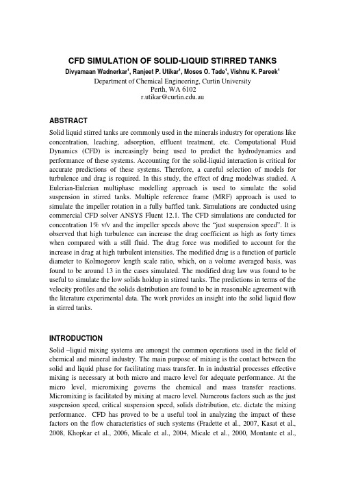
CFD SIMULATION OF SOLID-LIQUID STIRRED TANKSDivyamaan Wadnerkar , Ranjeet P. Utikar , Moses O. Tade , Vishnu K. Pareek1 1 1 1Department of Chemical Engineering, Curtin University Perth, WA 6102 r.utikar@.auABSTRACT Solid liquid stirred tanks are commonly used in the minerals industry for operations like concentration, leaching, adsorption, effluent treatment, etc. Computational Fluid Dynamics (CFD) is increasingly being used to predict the hydrodynamics and performance of these systems. Accounting for the solid-liquid interaction is critical for accurate predictions of these systems. Therefore, a careful selection of models for turbulence and drag is required. In this study, the effect of drag modelwas studied. A Eulerian-Eulerian multiphase modelling approach is used to simulate the solid suspension in stirred tanks. Multiple reference frame (MRF) approach is used to simulate the impeller rotation in a fully baffled tank. Simulations are conducted using commercial CFD solver ANSYS Fluent 12.1. The CFD simulations are conducted for concentration 1% v/v and the impeller speeds above the “just suspension speed”. It is observed that high turbulence can increase the drag coefficient as high as forty times when compared with a still fluid. The drag force was modified to account for the increase in drag at high turbulent intensities. The modified drag is a function of particle diameter to Kolmogorov length scale ratio, which, on a volume averaged basis, was found to be around 13 in the cases simulated. The modified drag law was found to be useful to simulate the low solids holdup in stirred tanks. The predictions in terms of the velocity profiles and the solids distribution are found to be in reasonable agreement with the literature experimental data. The work provides an insight into the solid liquid flow in stirred tanks.INTRODUCTION Solid –liquid mixing systems are amongst the common operations used in the field of chemical and mineral industry. The main purpose of mixing is the contact between the solid and liquid phase for facilitating mass transfer. In in industrial processes effective mixing is necessary at both micro and macro level for adequate performance. At the micro level, micromixing governs the chemical and mass transfer reactions. Micromixing is facilitated by mixing at macro level. Numerous factors such as the just suspension speed, critical suspension speed, solids distribution, etc. dictate the mixing performance. CFD has proved to be a useful tool in analyzing the impact of these factors on the flow characteristics of such systems (Fradette et al., 2007, Kasat et al., 2008, Khopkar et al., 2006, Micale et al., 2004, Micale et al., 2000, Montante et al.,Divyamaan Wadnerkar, Ranjeet P. Utikar, Moses O. Tade, Vishnu K. Pareek2001, Ochieng and Lewis, 2006). Proper evaluation of interphase drag is essential for accurate predictions using the CFD model. In this study four different drag models are analysed and their validity is checked by comparing the results of CFD simulations at low concentrations of solid with the experimental data available in the literature (Guha et al., 2007).LITERATURE REVIEW Micale et al. (2000) used Settling Velocity Model (SVM) and Multi fluid Model (MFM) approaches to analyse the particle distribution in stirred tanks. In SVM, it is assumed that the particles are transported as a passive scalar or molecular species but with a superimposed sedimentation flow, whereas in MFM, momentum balances are solved for both phases. Computationally intensive MFM was found to be better than SVM, but for both the models it was necessary to take into account the increase in drag with the increasing turbulence. Micale et. al. (2004) simulated the solids suspension of 9.6% and 20% volume fractions using the MFM approach and sliding grid (SG) approach using the Schillar Nauman drag model. Schillar Nauman is applicable on spherical particles in an infinite stagnant fluid and accounts for the inertial effect on the drag force acting on it. It provided satisfactory results at low impeller speed. Ochieng and Lewis (2006) simulated nickel solids loading of 1-20% w/w with impeller speeds between 200 and 700 RPM using both steady and transient simulations and found out that transient simulations, although time consuming, are better for stirred tank simulations. The initial flow field was generated using the multiple reference frame (MRF) approach and then the simulations were carried out using SG. The Gidaspow model was used for the drag factor, which is a combination of the Wen and Yu model and the Ergun equation (Ding and Gidaspow, 1990). Wen and Yu drag is appropriate for dilute systems and Ergun is used for dense packing. For the study of just suspended of solids using solids at the bottom of the tank as an initial condition, it provided satisfactory results. The suspension can also be modelled as a continuous phase using a viscosity law and the shear induced migration phenomenon generated by gradients in shear rates or concentration gradients can be captured at a macroscopic scale. For the prediction of shear-induced particle migration, the Shear Induced Migration Model (SIMM) was used, which states that, in a viscous concentrated suspension, small but non-Brownian particles migrate from regions of high shear rate to regions of low shear rate, and from regions of high concentrations to regions of low concentrations in addition to which settling by gravity is added. In the case of a mixing process, owing to the action of shear and inertia, the particles may segregate and demix, thereby generating concentration gradients in the vessel. This shear-induced migration phenomenon can be simulated at the macroscopic scale, where the suspension is modelled as one continuous phase2Divyamaan Wadnerkar, Ranjeet P. Utikar, Moses O. Tade, Vishnu K. Pareekthrough a viscosity law (Fradette et al., 2007). However, this model shows potentially erratic behavior in close-to-zero shear rate and high concentration zones. The dependency of the drag on the turbulence was numerically investigated by Khopkar at al. (2006) by conducting experiments using single phase flow through regularly arranged cylindrical objects. A relationship between the drag, particle diameter and Kolmogorov length scale was fit into the expression given by Brucato et al. (1998). They found that the drag predicted by the original Brucato drag model needs to be reduced by a factor of 10. This modified Brucato model was then used for the simulation of liquid flow field in stirred tanks (2008). It was able to capture the key features of liquid phase mixing process. Panneerselvam et al. (2008) used the Brucato drag law to simulate 7% v/v solids in liquid. MRF approach was used with Eulerian-Eulerian model. There was mismatch in the radial and tangential components of velocity at impeller plane. This discrepancy was attributed to the turbulent fluctuations that dominate the impeller region, which the model was not able to capture successfully. It is quite clear from the review that solids suspension and distribution is highly dependent on the turbulence and interphase drag in the tank. At low impeller speeds, turbulent fluctuations are less and hence do not affect the predictions much. However, at higher impeller speeds, the drag and turbulence become increasingly important. Moreover, there is no consensus on the appropriate drag for liquid-solid stirred tanks. Therefore, in this study, the impact of drag model on the flow distribution and the velocity fields is investigated. Different drag models are assessed to provide a clear understanding of the selection criterion of drag in a particular case.CFD MODEL Model Equations The hydrodynamic study is simulated using Eulerian-Eulerian multiphase model. Each phase, in this model, is treated as an interpenetrating continuum represented by a volume fraction at each point of the system. The Reynolds averaged mass and momentum balance equations are solved for each of the phases. The governing equations are given below: Continuity equation:3Divyamaan Wadnerkar, Ranjeet P. Utikar, Moses O. Tade, Vishnu K. PareekMomentum equation:Where q is 1 or 2 for primary or secondary phase respectively, α is volume fraction, ρ is density, is the velocity vector, P is pressure and is shared by both the phases, is the stress tensor because of viscosity and velocity fluctuations, g is gravity, to turbulent dissipation, force and is external force, is lift force, is force due is virtual massis interphase interaction force.The stress-strain tensor is due to viscosity and Reynolds stresses that include the effect of turbulent fluctuations. Using the Boussinesq’s eddy viscosity hypothesis the closure can be given to the above momentum transfer equation. The equation can be given as:Whereis the shear viscosity,is bulk viscosity and is the unit stress tensor.Equations for Turbulence k-ε mixture turbulence and k-ε dispersed turbulence models are used in the present study. The mixture turbulence model assumes the domain as a mixture and solves for k and ε values which are common for both the phases. In the dispersed turbulence model, the modified k-ε equations are solved for the continuous phase and the turbulence quantities of dispersed phase are calculated using Tchen-theory correlations. It also takes the fluctuations due to turbulence by solving for the interphase turbulent momentum transfer. For the sake of brevity, only the equations of mixture model for turbulence are given below. Other equations can be found in the Fluent user guide (ANSYS, 2009).are constants. The mixture density,andare turbulent Prandtl numbers. are computed from the equations below:and velocity,4Divyamaan Wadnerkar, Ranjeet P. Utikar, Moses O. Tade, Vishnu K. PareekTurbulent viscosity, equations below:and turbulence kinetic energy,are computed fromTurbulent Dispersion Force In the simulation of solid suspension in stirred tanks, the turbulent dispersion force is significant when the size of turbulence eddies is larger than the particle size (Kasat et al., 2008). Its significance is also highlighted in some previous studies (Ljungqvist and Rasmuson, 2001). The role of this force is also analysed in this study. It is incorporated along with the momentum equation and is given as follows:Where drift velocity,is given by,Dp and Dq are diffusivities and σpq is dispersion Prandtl number. Interphase Drag Force The drag force represents interphase momentum transfer due to the disturbance created by each phase. For dilute systems and low Reynolds number, particle drag is given by Stokes law and for high Reynolds number, the Schillar Nauman Drag Model can be used. In the literature review other drag models such as Gidaspow model (Ding and Gidaspow, 1990) and Wen and Yu model (Wen and Yu, 1966) have also been discussed. But for stirred tank systems, there should be a model that takes turbulence into account as with increasing Reynolds number and with the increase in the eddy sizes, the impact of turbulence on the drag increases. Considering this Brucato et al. (1998) proposed a new drag model making drag coefficient as a function of ratio of particle diameter and Kolmogorov length scales. So, with the change in the turbulence at some local point in the system, the drag will also change. The drag coefficient proposed by Brucato et al. is given below:5Divyamaan Wadnerkar, Ranjeet P. Utikar, Moses O. Tade, Vishnu K. Pareekwhere, K is constant with value Kolmogorov length scale., dP is particle diameter andisKhopkar et al. (2006) performed DNS simulations for conditions closer to those in stirred tanks. Based on these simulations they obtained a modified version of Brucato drag that is more appropriate for stirred tanks. This modified drag has a constant value of 8.67 X 10⁻⁵. In this paper, the Gidaspow, Wen and Yu, Brucato and modified Brucato Drag models are assessed.METHODOLOGY AND BOUNDARY CONDITIONS Vessel geometry In the current study, a flat bottomed cylindrical tank was simulated. The dimensions used are tank diameter, T = 0.2 m and tank height, H= T. The tank has four baffles mounted on the wall of width T/10. The shaft of the impeller (of diameter = 0.01m) was concentric with the axis of the tank. A six-bladed Rushton Turbine was used as an impeller. The Rushton turbine has a diameter, D = T/3. For each blade, the length =T/12 and the height = T/15. The impeller off-bottom clearance was (C = T/3) measured from the level of the impeller disc. The fluid for the system was water (ρ = 1000 kg / m3, µ = 0.001 Pa.s) and the solids were small glass particles of density 2550 kg / m3 and diameter of 0.3 mm. Numerical simulations Owing to the rotationally periodic nature, half of the tank was simulated. Multiple reference frame (MRF) approach was used. A reference moving zone with dimensions r = 0.06 m and 0.03995 < z < 0.09325 was created (where z is the axial distance from the bottom). The impeller rod outside this zone was considered as a moving wall. The top of the tank was open, so it was defined as a wall of zero shear. The specularity coefficient is 0 for smooth walls and is 1 for rough walls. The walls of stirred tank were assumed to be smooth and a very small specularity coefficient of 0.008 was given to all other walls. In the initial condition of the simulation, a uniform concentration of 0.01 v/v fraction glass particles was taken in the tank. The rotation speed of the impeller was 1000 rpm that was above the speed of just-suspension of glass particles in the liquid. For modelling the turbulence, a standard k- ε mixture model was used. The model parameters were Cµ : 0.09, C1 : 1.44, C2 : 1.92, σk: 1.0 and σε = 1.3. In few cases the standard k- ε dispersion model was also used with the turbulence Schmidt number, σ, taken as equal to 0.8. The steady state numerical solution of the system was obtained by using the commercial CFD solver ANSYS 12.1 FLUENT. In the present work,6Divyamaan Wadnerkar, Ranjeet P. Utikar, Moses O. Tade, Vishnu K. PareekSimple Pressure-Velocity coupling scheme was used along with the standard pressure discretization scheme.RESULTS AND DISCUSSION Preliminary numerical simulations In order to verify that the simulations have converged, the residuals as well as additional parameters namely turbulence dissipation over the volume and torque on the shaft were monitored. Once the residuals and additional parameters were constant, the simulation was deemed to have converged. Initial simulations were conducted to assess the effect of turbulence dispersion force. The flow field was analysed and it was found that there was negligible effect of this force in this particular case of 0.01 volume fraction. The turbulence dispersion force has higher influence at higher concentration of solids where its magnitude will be high enough to be comparable with the other forces being exerted on the secondary phase (Ljungqvist and Rasmuson, 2001). Flow Field Vectors in the domain converged solution showed similar flow field (velocity field vectors) as compared to that available in the literature (Guha et al., 2007). Figure 1 shows the velocity vectors on a center plane. All these characteristics of the flow are clearly visible in figure 1. For the Rushton turbine, an outward jet stream is formed due to the outward thrust of the impeller. This high velocity jet approaches Fig. 1: Velocity vectors of solids velocity for solid towards the wall of the volume fraction of 0.01 and 1000 RPM stirred tank and then splits into upward and downward direction. It creates an anticlockwise velocity field in the region above the impeller and a clockwise velocity field in the region below the impeller. The velocity near walls for the region above impeller is upwards and below the impeller is downwards. It is opposite when the velocity field is observed near the7Divyamaan Wadnerkar, Ranjeet P. Utikar, Moses O. Tade, Vishnu K. Pareekcentre. The intensity of the swirl in the region below the impeller is stronger than that above the impeller. Analysis of different drag models The simulations were run using different drag models and the results were then compared with the experimental data. The radial velocity of the solid particles at impeller plane is shown in Figure 2. Out of the four drag models wide disparity with experimental data was observed when using the Wen and Yu and the Gidaspow model. These two models predicted the highest radial velocities. The Brucato drag model slightly overpredicted the radial velocity, whereas the predictions from the modified Brucato drag were in reasonable agreement with experimental data. The solid velocities are higher at the impeller tip. As the solids approach towards wall, the velocity gradually decreases. Due to no slip condition on the wall, the velocity should gradually reach zero value at wall. But, quantitatively, there is an overprediction of the velocities in simulations in near wall region. The disparity can be attributed to lesser number of data points available for averaging in experiments. As the experiments clearly show a zero ensemble averaged value even at (rRi/(R-Ri) = 0.8. At low solid concentrations, Gidaspow drag model acts like Wen and Yu model and at higher concentrations it takes the form of the Ergun equation. Therefore, both Wen and Yu model and Gidaspow models predict the same result. The modified Brucato drag model accounts for the effect of solid phase on the turbulence. At higher impeller speed,Fig. 2: Radial velocity at impeller plane for 0.01 solid volume fraction and 1000 RPM.Fig. 3: Radial velocity at axial plane r/R -0.5 for 0.01 solid volume fraction and 1000 RPM.Fig. 4: Tangential velocity at axial plane r/R – 0.5 for 0.01 solid volume fraction and 1000 RPM.8Divyamaan Wadnerkar, Ranjeet P. Utikar, Moses O. Tade, Vishnu K. Pareekthe role of turbulence in calculation of drag is vital factor, hence, the modified Brucato drag model predicts better results as compared to the other drag models. Figure 3 shows the comparison between the simulations results and experimental data for radial velocity at axial plane r/R = 0.5. A positive radial velocity is expected in the upper zone of the impeller. A slight negative radial velocity in the zone below impeller suggests a strong flow towards the centre of the stirred tank in that region. It indicates the presence of strong clockwise currents. All the drag models could qualitatively capture this Fig. 5: Axial velocity at axial plane r/R – 0.5 for flow behaviour. For the 0.01 solid volume fraction and 1000 RPM. experimental data, the highest tangential velocity is observed at z/T = 0.36 ± 0.04. This compares well the simulation result of z/T = 0.34. In the lower region of the stirred tank, where the effect of turbulence is not as prominent as the upper region, the predictions from all the drag models compared well with experimental data. In the upper region, discrepancy was observed. Around the impeller zone, where, the turbulence and velocity fluctuations are higher, the Wen and Yu and Gidaspow drag models show large overprediction compared to the experimental data. On the other hand, the Brucato and modified Brucato drag show reasonable agreement. Figure 4 shows the comparison between the simulations results and experimental data for tangential velocity at axial plane r/R = -0.5. Similar trend to that observed in radial velocity is observed. The axial velocity profile is shown in Figure 5. The reversal of flow can be clearly seen. Above the impeller, the axial velocities are negative that means the flow is in downward direction. It reverses in the region below impeller. At the impeller, the axial velocity is zero and is distributed as the other two components of velocities viz. radial and tangential. All the drag models were able to capture the flow reversal qualitatively. Moreover, the predictions of all the drag models were comparable. The experiments show higher axial velocity in the lower region compared to the upper region, whereas, the simulations predicted similar velocities in the lower and upper region of the impeller. Although this phenomenon is visible in figure 1, the axial velocities shown in figure 5 fail to predict it. It is because of the bigger circular loop in the lower region of the impeller clearly seen in figure 1, which also affects the ensemble averaging of values in9Divyamaan Wadnerkar, Ranjeet P. Utikar, Moses O. Tade, Vishnu K. Pareekthis particular zone. At the impeller plane, the axial velocity is zero as it is distributed as the other two components of velocities. CONCLUSION AND SCOPE OF FURTHER STUDY CFD simulations of solid suspension in stirred tank were performed. The predictions of four different drag models were compared. It was observed that turbulence dispersion force had negligible effect due to a low volume fraction of solids. Axial, radial and tangential velocities were compared at different axial locations. It was observed that all four models could qualitatively capture the flow in stirred tank. The Wen and Yu and Gidaspow model showed biggest deviation from the experimental data while results form the modified Brucato drag model were in reasonable agreement for the liquid flow fields. Future study includes extending the comparison and validation studies to higher solid concentrations, where the effect of solids on the turbulence is expected to increase. REFERENCES ANSYS 2009. Fluent User Guide. ANSYS Inc., Canonsburg, PA, www. fluent. com. BRUCATO, A., GRISAFI, F. & MONTANTE, G. 1998. Particle drag coefficients in turbulent fluids. Chemical Engineering Science, 53, 3295-3314. DING, J. & GIDASPOW, D. 1990. A bubbling fluidization model using kinetic theory of granular flow. AIChE Journal, 36, 523-538. FRADETTE, L., TANGUY, P. A., BERTRAND, F. O., THIBAULT, F., RITZ, J.-B. T. & GIRAUD, E. 2007. CFD phenomenological model of solid-liquid mixing in stirred vessels. Computers & Chemical Engineering, 31, 334-345. GUHA, D., RAMACHANDRAN, P. A. & DUDUKOVIC, M. P. 2007. Flow field of suspended solids in a stirred tank reactor by Lagrangian tracking. Chemical Engineering Science, 62, 6143-6154. KASAT, G. R., KHOPKAR, A. R., RANADE, V. V. & PANDIT, A. B. 2008. CFD simulation of liquid-phase mixing in solid-liquid stirred reactor. Chemical Engineering Science, 63, 3877-3885. KHOPKAR, A. R., KASAT, G. R., PANDIT, A. B. & RANADE, V. V. 2006. Computational Fluid Dynamics Simulation of the Solid Suspension in a Stirred Slurry Reactor. Industrial & Engineering Chemistry Research, 45, 4416-4428. LJUNGQVIST, M. & RASMUSON, A. 2001. Numerical Simulation of the Two-Phase Flow in an Axially Stirred Vessel. Chemical Engineering Research and Design, 79, 533546. MICALE, G., GRISAFI, F., RIZZUTI, L. & BRUCATO, A. 2004. CFD Simulation of Particle Suspension Height in Stirred Vessels. Chemical Engineering Research and Design, 82, 1204-1213. MICALE, G., MONTANTE, G., GRISAFI, F., BRUCATO, A. & GODFREY, J. 2000. CFD Simulation of Particle Distribution in Stirred Vessels. Chemical Engineering Research and Design, 78, 435-444. MONTANTE, G., MICALE, G., MAGELLI, F. & BRUCATO, A. 2001. Experiments and CFD Predictions of Solid Particle Distribution in a Vessel Agitated with Four Pitched Blade Turbines. Chemical Engineering Research and Design, 79, 1005-1010. OCHIENG, A. & LEWIS, A. E. 2006. CFD simulation of solids off-bottom suspension and cloud height. Hydrometallurgy, 82, 1-12.10Divyamaan Wadnerkar, Ranjeet P. Utikar, Moses O. Tade, Vishnu K. Pareek PANNEERSELVAM, R., SAVITHRI, S. & SURENDER, G. D. 2008. CFD modeling of gas-liquid-solid mechanically agitated contactor. Chemical Engineering Research and Design, 86, 1331-1344WEN, C. Y. & YU, Y. H. Year. Mechanics of Fluidization. In: Chemical Engineering Progress Symposium Series, 1966. 100-111.11。
THERMAL CONDUCTIVITY OF LIQUIDS
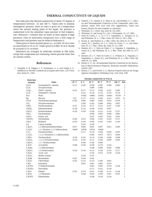
6-220THERMAL CONDUCTIVITY OF LIQUIDSThis table gives the thermal conductivity of about 275 liquids at temperatures between –25 and 100 ° C. Values refer to nominal atmospheric pressure; when an entry is given for a temperature above the normal boiling point of the liquid, the pressure is understood to be the saturation vapor pressure at that tempera-ture. Reference 1 contains data on many of these liquids at high pressures. Data on halocarbon refrigerants over a wide range of temperature and pressure may be found in Reference 6.Values given to three decimal places (i.e., to 0.001 W/m K) have an uncertainty of 2% to 5%. Values given to 0.0001 W/m K should be accurate to 1% or better.Substances are arranged by molecular formula in Hill order,except that compounds not containing carbon precede those that do contain carbon.References1.Vargaftik, N. B., Filippov, L. P ., Tarzimanov, A. A., and Totskii, E. E., Handbook of Thermal Conductivity of Liquids and Gases , CRC Press,Boca Raton FL, 1994.2.Daubert, T. E., Danner, R. P ., Sibul, H. M., and Stebbins, C. C., Physi-cal and Thermodynamic Properties of Pure Compounds: Data Com-pilation , extant 1994 (core with four supplements), Taylor and Francis, Bristol, PA (also available as a database).3.Watanabe, H., J. Chem. Eng. Data 48, 124, 2003.4.Watanabe, H., and Seong, D. J., Int. J. Thermophys . 23, 337, 2002.5.Nieto de Castro, C. A., Li, S. F. Y., Nagashima, A., Trengove, R. D.,and Wakeham, W. A., J. Phys. Chem. Ref. Data 15, 1073, 1986.6.Krauss, R., and Stephan, K., J. Phys. Chem. Ref. Data 18, 43, 1989.7.Assael, M. J., Ramires, M. L. V., Nieto de Castro, C. A., and Wake-ham, W. A., J. Phys. Chem. Ref. Data 19, 113, 1990.8.Ramires, M. L. V ., Nieto de Castro, C. A., Nagasaka, Y., Nagashima, A.,Assael, M. J., and Wakeham, W . A., J. Phys. Chem. Ref. Data 24, 1377,1995.9.Ramires, M. L. V., Nieto de Castro, C. A., Perkins, R. A., Nagasaka, Y.,Nagashima, A., Assael, M. J., and Wakeham, W. A., J. Phys. Chem. Ref.Data 29, 133, 2000.10.Marsh, K. N., Ed., Recommended Reference Materials for the Realiza-tion of Physicochemical Properties , Blackwell Scientific Publications,Oxford, 1987.11.Beaton, C. F., and Hewitt, G. F., Physical Property Data for the DesignEngineer , Hemisphere Publishing Corp., New York, 1989.Molecular formula NameCl 4 Ge Germanium(IV) chloride 0.1110.1050.1000.0950.0900.0841 Cl 4 Si Tetrachlorosilane 0.0990.0962Cl 4 Sn Tin(IV) chloride0.1230.1170.1120.1060.1010.0951 Cl 4 Ti Titanium(IV) chloride 0.1430.1380.1340.1290.1241 H 2 O Water 0.55620.60620.64230.66430.67298 Hg Mercury7.858.1758.5148.8429.1619.47511 CCl 3 F Trichlorofluoromethane 0.1020.0960.0890.0830.0760.0701 CCl 4 Tetrachloromethane 0.1090.1030.0980.0920.0871 CHCl 3 Trichloromethane 0.1270.1220.1170.1120.1070.1022CH 2 Br 2 Dibromomethane 0.1200.1140.1080.1030.0972CH 2 Cl 2 Dichloromethane 0.1580.1490.1400.1330.1280.1271 CH 2 I 2 Diiodomethane 0.0980.0930.0880.0831 CH 2 O 2 Formic acid 0.2670.2650.2630.2611 CH 3 NO 2 Nitromethane 0.2260.2150.2040.1930.1820.1711 CH 4 O Methanol0.2180.2100.2020.1950.1890.1821CS 2Carbon disulfide0.1540.1492C 2 Br 2 F 4 1,2-Dibromotetrafluoroethane0.0710.0660.0610.0570.0530.0491C 2 Cl 3 F 3 1,1,2-Trichloro-1,2,2-trifluoroethane 0.08470.07900.07360.06836C 2 Cl 4 Tetrachloroethene0.1170.1100.1040.0980.0931 C 2 Cl 4 F 2 1,1,2,2-Tetrachloro-1,2-difluoroethane 0.0820.0780.0740.0691 C 2 HCl 3 Trichloroethene0.1280.1210.1140.1060.0980.0901 C 2 H 2 Cl 4 1,1,2,2-Tetrachloroethane 0.1240.1180.1110.1040.0980.0911C 2 H 3 Cl 3 1,1,1-Trichloroethane 0.1060.1010.0962 C 2 H 3 N Acetonitrile0.2080.1980.1880.1780.1682C 2 H 4 Br 2 1,2-Dibromoethane 0.1000.0960.0920.0881 C 2 H 4 Cl 2 1,2-Dichloroethane 0.1440.1390.1330.1280.1220.1171 C 2 H 4 O 2 Acetic acid 0.1580.1530.1490.1442C 2 H 4 O 2 Methyl formate 0.1940.1871 C 2 H 5 Br Bromoethane 0.1070.1040.1011 C 2 H 5 Cl Chloroethane 0.1450.1320.1190.1060.0932 C 2 H 5 I Iodoethane0.0910.0870.0830.0791C 2 H 5 NO N -Methylformamide 0.2030.2010.1990.1962C 2 H 5 NO 2 Nitroethane 0.1730.1610.1491C 2 H 6 O Ethanol0.1810.1740.1670.1600.1530.1481 C 2 H 6 O 2 1,2-Ethanediol 0.2480.2540.2580.2610.2611C 2 H 7 NOEthanolamine0.2400.2380.2361Thermal Conductivity of Liquids6-221C 3F8Perfluoropropane0.0620.0560.0510.0460.0410.0351C 3H3N Acrylonitrile0.1860.1760.1660.1560.1460.1361C 3H5ClO Epichlorohydrin0.1420.1370.1310.1250.1190.1142C 3H6O Allyl alcohol0.1621C 3H6O Acetone0.1690.1612C 3H6O Methyloxirane0.1810.1711C 3H6O2Propanoic acid0.1470.1440.1410.1390.1361C 3H6O2Ethyl formate0.1810.1710.1600.1490.1381C 3H6O2Methyl acetate0.1740.1640.1530.1430.1330.1222C 3H7Br1-Bromopropane0.1080.1040.0990.0941C 3H7Cl1-Chloropropane0.1290.1230.1160.1100.1040.0981C 3H7I1-Iodopropane0.0960.0920.0870.0830.0780.0741C 3H7I2-Iodopropane0.0890.0850.0820.0780.0740.0711C 3H7NO N,N-Dimethylformamide0.1830.1750.1670.1591C 3H7NO21-Nitropropane0.1520.1440.1371C 3H8O1-Propanol0.1620.1580.1540.1490.1450.1412C 3H8O2-Propanol0.1460.1410.1350.1290.1240.1182C 3H8O21,2-Propanediol0.1990.2000.2000.2000.1990.1971C 3H8O22-Methoxyethanol0.1900.1800.1701C 3H8O3Glycerol0.2850.2880.2920.2961C 3H9N Trimethylamine0.1430.1332C 4F8Perfluorocyclobutane0.0820.0720.0630.0530.0440.0341C 4H4O Furan0.1420.1340.1262C 4H4S Thiophene0.1990.1950.1910.1862C 4H61,2-Butadiene0.1470.1341C 4H62-Butyne0.1370.1290.1212C 4H6O2Vinyl acetate0.1510.1410.1310.1201C 4H6O3Acetic anhydride0.1700.1640.1580.1520.1461C 4H8O Butanal0.1550.1470.1400.1321C 4H8O2-Butanone0.1580.1510.1450.1390.1332C 4H8O Tetrahydrofuran0.1320.1260.1200.1142C 4H8O2Propyl formate0.1510.1440.1370.1301C 4H8O2Ethyl acetate0.1510.1440.1361C 4H8O2Methyl propanoate0.1410.1371C 4H8O21,4-Dioxane0.1590.1470.1350.1232C 4H9Br1-Bromobutane0.1120.1070.1030.0980.0930.0881C 4H9I1-Iodobutane0.0940.0900.0850.0810.0771C 4H9NO N,N-Dimethylacetamide0.1750.1720.1681C 4H10O1-Butanol0.1580.1530.1470.1420.1371C 4H10O2-Methyl-2-propanol0.1120.1100.1090.1081C 4H10O Diethyl ether0.1500.1400.1300.1200.1100.1002C 4H10O22-Ethoxyethanol0.1900.1820.1740.1651C 5H5N Pyridine0.1710.1660.1620.1570.1531C 5H6O2Furfuryl alcohol0.1791C 5H82-Methyl-1,3-butadiene0.1410.1300.1191C 5H81-Pentyne0.1440.1360.1270.1191C 5H8Cyclopentene0.1430.1360.1292C 5H8O2Methyl methacrylate0.1560.1470.1370.1270.1171C 5H8O22,4-Pentanedione0.1540.1500.1460.1431C 5H9NO N-Methyl-2-pyrrolidone0.1670.1620.1571C 5H101-Pentene0.1310.1240.1162C 5H10Cyclopentane0.1400.1330.1262C 5H10O Pentanal0.1460.1390.1330.1270.1211C 5H10O2-Pentanone0.1490.1420.1350.1280.1211C 5H10O3-Pentanone0.1510.1440.1370.1290.1221C 5H10O2Pentanoic acid0.1400.1370.1330.1301C 5H10O2Butyl formate0.1360.1300.1230.1171C 5H10O2Propyl acetate0.1460.1400.1350.1300.1241C 5H10O2Ethyl propanoate0.1330.1211C 5H10O2Methyl butanoate0.1401C 5H11Br1-Bromopentane0.1130.1090.1050.1010.0970.0931C 5H11Cl1-Chloropentane0.1250.1200.1150.1091Molecularformula NameC 5H11I1-Iodopentane0.0960.0920.0880.0840.0811C 5H12Pentane0.1300.12070.11130.10180.09230.0834C 5H12Isopentane0.1111C 5H12O1-Pentanol0.1590.1550.1500.1450.1410.1361C 5H12O2-Methyl-2-butanol0.1190.1160.1130.1090.1061C 5H12O21,5-Pentanediol0.2210.2221C 5H12O3Diethylene glycol monomethyl ether0.1900.1850.1800.1751C 6F6Hexafluorobenzene0.0831C 6F14Perfluorohexane0.0670.0650.0641C 6H3Cl31,2,3-Trichlorobenzene0.1100.1080.1061C 6H3Cl31,2,4-Trichlorobenzene0.1120.1090.1061C 6H4Cl2o-Dichlorobenzene0.1250.1210.1170.1130.1091C 6H4Cl2m-Dichlorobenzene0.1200.1160.1130.1091C 6H4Cl2p-Dichlorobenzene0.1120.1080.1051C 6H5Br Bromobenzene0.1190.1150.1110.1070.1030.0991C 6H5Cl Chlorobenzene0.1370.1320.1270.1230.1180.1131C 6H5F Fluorobenzene0.1360.1310.1261C 6H5I Iodobenzene0.1060.1030.1010.0980.0950.0921C 6H5NO2Nitrobenzene0.1490.1450.1420.1391C 6H6Benzene0.14110.13290.12477C 6H6ClN2-Chloroaniline0.1481C 6H6O Phenol0.1530.1490.1471C 6H7N Aniline0.1751C 6H8N2Hexanedinitrile0.1740.1681C 6H10Cyclohexene0.1420.1360.1300.1240.1182C 6H10O Cyclohexanone0.1380.1340.1300.1261C 6H10O Mesityl oxide0.1700.1630.1560.1490.1420.1342C 6H10O3Ethyl acetoacetate0.1550.1520.1480.1441C 6H10O4Diethyl oxalate0.1571C 6H121-Hexene0.1380.1290.1210.1131C 6H12Cyclohexane0.1230.1170.1112C 6H12O2-Hexanone0.1560.1450.1340.1240.1151C 6H12O Cyclohexanol0.1380.1340.1300.1261C 6H12O2Hexanoic acid0.1480.1420.1370.1311C 6H12O2Butyl acetate0.1430.1360.1300.1230.1161C 6H12O2Propyl propanoate0.1331C 6H12O2Ethyl butanoate0.1430.1370.1310.1261C 6H12O2Methyl pentanoate0.1430.1380.1320.1271C 6H12O3Paraldehyde0.1301C 6H13Br1-Bromohexane0.1150.1110.1080.1040.1010.0971C 6H13I1-Iodohexane0.0980.0950.0910.0880.0841C 6H14Hexane0.1330.12500.11670.10830.09990.0924C 6H142-Methylpentane0.1200.11270.10500.09720.08940.0823C 6H143-Methylpentane0.1220.11420.10640.09860.09090.0833C 6H142,2-Dimethylbutane0.1080.10060.09340.08610.07880.0723C 6H142,3-Dimethylbutane0.1150.10760.10030.09300.08570.0783C 6H14O1-Hexanol0.1610.1570.1520.1470.1420.1371C 6H14O Dipropyl ether0.1370.1300.1230.1171C 6H14O21,2-Diethoxyethane0.1400.1330.1251C 6H14O3Diethylene glycol monoethyl ether0.1880.1840.1801C 6H14O4Triethylene glycol0.1930.1950.1960.1960.1961C 6H15N Triethylamine0.1460.1390.1320.1250.1180.1111C 7F16Perfluoroheptane0.0680.0640.0600.0560.0531C 7H5N Benzonitrile0.1480.1420.1360.1301C 7H6O Benzaldehyde0.1530.1480.1430.1391C 7H8Toluene0.14550.13850.13100.12350.11620.10959C 7H8O o-Cresol1C 7H8O m-Cresol0.1490.1470.1451C 7H8O Benzyl alcohol0.1590.1580.1560.1541C 7H8O Anisole0.1450.1420.1390.1361C 7H9N2-Methylaniline0.1621C 7H9N3-Methylaniline0.1611C 7H141-Heptene0.1390.1320.1250.1180.1111C 7H14Cycloheptane0.1230.1180.1120.1081C 7H14O Heptanal0.1401C 7H14O3-Heptanone0.1430.1370.1310.1250.1191C 7H14O4-Heptanone0.1360.1310.1250.1201C 7H14O2Hexyl formate0.1410.1330.1260.1191C 7H14O2Heptanoic acid0.1400.1370.1331C 7H14O2Pentyl acetate0.1410.1340.1260.1200.1131C 7H14O2Butyl propanoate0.1390.1330.1260.1211C 7H14O2Ethyl pentanoate0.1321C 7H14O2Methyl hexanoate0.1360.1310.1260.1211C 7H16Heptane0.13780.13030.12280.11520.10775C 7H162-Methylhexane0.1250.11770.11050.10330.09610.0893C 7H163-Methylhexane0.1260.11840.11120.10400.09680.0903C 7H163-Ethylpentane0.1280.12030.11280.10530.09780.0903C 7H162,2-Dimethylpentane0.1110.10460.09800.09130.08470.0783C 7H162,3-Dimethylpentane0.1200.11270.10590.09900.09220.0853C 7H162,4-Dimethylpentane0.1160.10890.10200.09510.08820.0813C 7H163,3-Dimethylpentane0.1130.10680.10010.09340.08670.0803C 7H162,2,3-Trimethylbutane0.1070.10110.09500.08890.08280.0773C 7H16O1-Heptanol0.1600.1580.1530.1490.1440.1391C 8F18Perfluorooctane0.0660.0620.0590.0550.0521C 8H8Styrene0.1480.1420.1370.1310.1260.1202C 8H8O Acetophenone0.1470.1460.1440.1421C 8H8O2Methyl benzoate0.1471C 8H10Ethylbenzene0.1430.1370.1300.1230.1160.1101C 8H10o-Xylene0.1310.1260.1200.1142C 8H10m-Xylene0.1300.1240.1180.1132C 8H10p-Xylene0.1300.1240.1180.1122C 8H10O Ethoxybenzene0.1510.1450.1400.1350.1301C 8H10O22-Phenoxyethanol0.1690.1680.1660.1651C 8H11N N-Ethylaniline0.1501C 8H11N N,N-Dimethylaniline0.1220.1190.1151C 8H161-Octene0.1390.1330.1260.1200.1140.1071C 8H16O2-Octanone0.1410.1350.1290.1240.1181C 8H16O2Heptyl formate0.1410.1370.1320.1280.1231C 8H16O2Octanoic acid0.1460.1430.1390.1351C 8H16O2Hexyl acetate0.1350.1290.1230.1181C 8H16O2Pentyl propanoate0.1380.1321C 8H16O2Ethyl hexanoate0.1420.1370.1330.1280.1231C 8H17Cl1-Chlorooctane0.1300.1270.1240.1210.1191C 8H18Octane0.1390.13170.12440.11710.10970.1024C 8H182-Methylheptane0.1270.12060.11390.10720.10050.0943C 8H183-Methylheptane0.1280.12160.11490.10810.10140.0953C 8H182,2,4-Trimethylpentane0.1070.10070.09480.08880.08290.0773C 8H182,3,4-Trimethylpentane0.1150.10930.10350.09760.09180.0863C 8H18O Ethyl hexyl ether0.1310.1260.1200.1140.1091C 8H18O1-Octanol0.1620.1580.1530.1480.1431C 8H18O Dibutyl ether0.1390.1320.1250.1180.1121C 8H18O3Diethylene glycol monobutyl ether0.1630.1580.1530.1481C 8H18O4Triethylene glycol dimethyl ether0.1690.1580.1471C 8H18O5Tetraethylene glycol0.1910.1921C 9H7N Quinoline0.1470.1440.1410.1381C 9H10Indan0.1351C 9H10O2Ethyl benzoate0.1411C 9H12Propylbenzene0.1340.1300.1250.1200.1150.1091C 9H12Isopropylbenzene0.1320.1280.1230.1180.1120.1071C 9H121,2,4-Trimethylbenzene0.1290.1240.1180.1141C 9H121,3,5-Trimethylbenzene0.1430.1390.1340.1290.1230.1171C 9H181-Nonene0.1360.1300.1230.1160.1100.1041C 9H18O2Nonanoic acid0.1500.1460.1420.1381C 9H18O2Heptyl acetate0.1350.1280.1220.1161C 9H19Br1-Bromononane0.1160.1120.1090.1060.1031C 9H19Cl1-Chlorononane0.1320.1280.1240.1200.1151C 9H19I1-Iodononane0.1050.1020.0990.0950.0921C 9H20Nonane0.1410.13370.12690.12010.11330.1064C 9H20O1-Nonanol0.1640.1590.1550.1500.1451C 10H7Br1-Bromonaphthalene0.1100.1090.1080.1061C 10H7Cl1-Chloronaphthalene0.1261C 10H10O4Dimethyl phthalate0.14730.14430.14090.137310C 10H121,2,3,4-Tetrahydronaphthalene0.1310.1290.1280.1261C 10H14Butylbenzene0.1260.1210.1160.1111C 10H14sec-Butylbenzene, (±)-0.1290.1240.1190.1140.1081C 10H14tert-Butylbenzene0.1170.1140.1100.1061C 10H141-Isopropyl-4-methylbenzene0.1320.1270.1220.1170.1120.1072C 10H14o-Diethylbenzene0.1330.1270.1220.1160.1111C 10H18trans-Decahydronaphthalene0.1131C 10H201-Decene0.1380.1320.1260.1200.1140.1091C 10H20O Decanal0.1490.1440.1390.1340.1291C 10H20O2Heptyl propanoate0.1370.1320.1270.1221C 10H20O2Hexyl butanoate0.1370.1320.1270.1211C 10H20O2Decanoic acid0.1480.1440.1401C 10H22Decane0.1420.13600.12960.12320.11670.1104C 10H22O1-Decanol0.1620.1590.1550.1511C 10H22O Dipentyl ether0.1310.1250.1210.1161C 10H22O21,2-Dibutoxyethane0.1400.1340.1270.1201C 11H16Pentylbenzene0.1350.1300.1250.1200.1151C 11H221-Undecene0.1260.1180.1140.1081C 11H22O6-Undecanone0.1370.1320.1271C 11H22O2Undecanoic acid0.1530.1491C 11H22O2Octyl propanoate0.1350.1300.1250.1201C 11H22O2Heptyl butanoate0.1390.1340.1290.1231C 11H24Undecane0.1360.1280.1220.1161C 11H24O1-Undecanol0.1690.1650.1610.1581C 12H10O Diphenyl ether0.1390.1350.1312C 12H14O4Diethyl phthalate0.1720.1690.1661C 12H16Cyclohexylbenzene0.1210.1190.1171C 12H18Hexylbenzene0.1410.1370.1320.1280.1241C 12H24O2Decyl acetate0.1460.1360.1261C 12H24O2Octyl butanoate0.1390.1340.1290.1251C 12H26Dodecane0.1350.1300.1240.1191C 12H26O1-Dodecanol0.1670.1630.1591C 12H26O3Diethylene glycol dibutyl ether0.1500.1460.1430.1390.1351C 12H27N Tributylamine0.1291C 13H261-Tridecene0.1300.1250.1200.1151C 13H28Tridecane0.1300.1250.1200.1151C 14H281-Tetradecene0.1360.1310.1260.1211C 14H30Tetradecane0.1390.1340.1290.1241C 14H30O1-Tetradecanol0.1670.1620.1572C 16H22O4Dibutyl phthalate0.1390.1360.1340.1310.1291C 16H34Hexadecane0.1400.1350.1300.1252C 18H38Octadecane0.1460.1420.1372C 20H40O2Butyl palmitate0.1510.1480.1440.1401C 22H42O2Butyl oleate0.1570.1530.1490.1451C 22H42O4Dioctyl hexanedioate0.1570.1530.1490.1451。
SOLIDWORKS Flow Simulation 产品说明书
OBJECTIVESOLIDWORKS® Flow Simulation is a powerful Computational Fluid Dynamics (CFD) solution fully embedded within SOLIDWORKS. It enables designers and engineers to quickly and easily simulate the effect of fluid flow, heat transfer and fluid forces that are critical to the success of their designs.OVERVIEWSOLIDWORKS Flow Simulation enables designers to simulate liquid and gas flow in real-world conditions, run “what if” scenarios and efficiently analyze the effects of fluid flow, heat transfer and related forces on or through components. Design variations can quickly be compared to make better decisions, resulting in products with superior performance. SOL IDWORKS Flow Simulation offers two flow modules that encompass industry specific tools, practices and simulation methodologies—a Heating, Ventilation and Air Conditioning (HVAC) module and an Electronic Cooling module. These modules are add-ons to a SOLIDWORKS Flow Simulation license. BENEFITS• Evaluates product performance while changing multiple variables at a rapid pace.• Reduces time-to-market by quickly determining optimal design solutions and reducing physical prototypes.• Enables better cost control through reduced rework and higher quality.• Delivers more accurate proposals.CAPABILITIESSOLIDWORKS Flow SimulationSOLIDWORKS Flow Simulation is a general-purpose fluid flow and heat transfer simulation tool integrated with SOLIDWORKS 3D CAD. Capable of simulating both low-speed and supersonic flows, this powerful 3D design simulation tool enables true concurrent engineering and brings the critical impact of fluid flow analysis and heat transfer into the hands of every designer. In addition to SOL IDWORKS Flow Simulation, designers can simulate the effects of fans and rotating components on the fluid flow and well as component heating and cooling. HVAC ModuleThis module offers dedicated simulation tools for HVAC designers and engineers who need to simulate advanced radiation phenomena. It enables engineers to tackle the tough challenges of designing efficient cooling systems, lighting systems or contaminant dispersion systems. Electronic Cooling ModuleThis module includes dedicated simulation tools for thermal management studies. It is ideal for companies facing thermal challenges with their products and companies that require very accurate thermal analysis of their PCB and enclosure designs.SOLIDWORKS Flow Simulation can be used to:• Dimension air conditioning and heating ducts with confidence, taking into account materials, isolation and thermal comfort.• Investigate and visualize airflow to optimize systems and air distribution.• Test products in an environment that is as realistic as possible.• Produce Predicted Mean Vote (PMV) and Predicted Percent Dissatisfied (PPD) HVAC results for supplying schools and government institutes.• Design better incubators by keeping specific comfort levels for the infant and simulating where support equipment should be placed.• Design better air conditioning installation kits for medical customers.• Simulate electronic cooling for LED lighting.• Validate and optimize designs using a multi-parametric Department of Energy (DOE) method.SOLIDWORKS FLOW SIMULATIONOur 3D EXPERIENCE® platform powers our brand applications, serving 12 industries, and provides a rich portfolio of industry solution experiences.Dassault Syst èmes, t he 3D EXPERIENCE® Company, provides business and people wit h virt ual universes t o imagine sust ainable innovat ions. It s world-leading solutions transform the way products are designed, produced, and supported. Dassault Systèmes’ collaborative solutions foster social innovation, expanding possibilities for the virtual world to improve the real world. The group brings value to over 220,000 customers of all sizes in all industries in more than 140 countries. For more information, visit .Europe/Middle East/Africa Dassault Systèmes10, rue Marcel Dassault CS 4050178946 Vélizy-Villacoublay Cedex France AmericasDassault Systèmes 175 Wyman StreetWaltham, Massachusetts 02451-1223USA Asia-PacificDassault Systèmes K.K.ThinkPark Tower2-1-1 Osaki, Shinagawa-ku,Tokyo 141-6020Japan©2018 D a s s a u l t S y s t èm e s . A l l r i g h t s r e s e r v e d . 3D E X P E R I E N C E ®, t h e C o m p a s s i c o n , t h e 3D S l o g o , C A T I A , S O L I D W O R K S , E N O V I A , D E L M I A , S I M U L I A , G E O V I A , E X A L E A D , 3D V I A , B I O V I A , N E T V I B E S , I F W E a n d 3D E X C I T E a r e c o m m e r c i a l t r a d e m a r k s o r r e g i s t e r e d t r a d e m a r k s o f D a s s a u l t S y s t èm e s , a F r e n c h “s o c i ét é e u r o p ée n n e ” (V e r s a i l l e s C o m m e r c i a l R e g i s t e r # B 322 306 440), o r i t s s u b s i d i a r i e s i n t h e U n i t e d S t a t e s a n d /o r o t h e r c o u n t r i e s . A l l o t h e r t r a d e m a r k s a r e o w n e d b y t h e i r r e s p e c t i v e o w n e r s . U s e o f a n y D a s s a u l t S y s t èm e s o r i t s s u b s i d i a r i e s t r a d e m a r k s i s s u b j e c t t o t h e i r e x p r e s s w r i t t e n a p p r o v a l .• Free, forced and mixed convection• Fluid flows with boundary layers, including wall roughness effects• Laminar and turbulent fluid flows • Laminar only flow• Multi-species fluids and multi-component solids• Fluid flows in models with moving/rotating surfaces and/or parts• Heat conduction in fluid, solid and porous media with/without conjugate heat transfer and/or contact heat resistance between solids• Heat conduction in solids only • Gravitational effectsAdvanced Capabilities• Noise Prediction (Steady State and Transient)• Free Surface• Radiation Heat Transfer Between Solids • Heat sources due to Peltier effect• Radiant flux on surfaces of semi-transparent bodies• Joule heating due to direct electric current in electrically conducting solids• Various types of thermal conductivity in solid medium • Cavitation in incompressible water flows• Equilibrium volume condensation of water from steam and its influence on fluid flow and heat transfer• Relative humidity in gases and mixtures of gases • Two-phase (fluid + particles) flows • Periodic boundary conditions.• Tracer Study• Comfort Parameters • Heat Pipes • Thermal Joints• Two-resistor Components • PCBs•Thermoelectric Coolers• Test the heat exchange on AC and DC power converters.• Simulate internal temperature control to reduce overheating issues.• Better position fans and optimize air flux inside a design.• Predict noise generated by your designed system.Some capabilities above need the HVAC or Electronic Cooling Module.SOLIDWORK Design Support• Fully embedded in SOLIDWORKS 3D CAD• Support SOLIDWORKS configurations and materials • Help Documentation • Knowledge base• Engineering database• eDrawings ® of SOLIDWORKS Simulation results General Fluid Flow Analysis• 2D flow • 3D flow • Symmetry• Sector Periodicity • Internal fluid flows • External fluid flowsAnalysis Types• Steady state and transient fluid flows • Liquids • Gases• Non-Newtonian liquids • Mixed flows• Compressible gas and incompressible fluid flows •Subsonic, transonic and supersonic gas flowsMesher• Global Mesh Automatic and Manual settings • Local mesh refinementGeneral Capabilities• Fluid flows and heat transfer in porous media • Flows of non-Newtonian liquids • Flows of compressible liquids •Real gases。
化工专业英语
Text
A centrifugal pump for liquids may be represented
as Whereas a centrifugal gas compressor may be represented as or simply
这就是单元操作的概念,是二十世纪初期新兴的化学工程学科所 采用的最基础和古老的概念。
Text
The five most common units are reactors, heat exchangers, pumps, mixers, and separators.
五个最常见的单元是反应器,热交换器,泵,混合器和分离器。
最后,我们说明两种流程图中所用的格式惯例。如果两股流动交叉,应当指 明其是否混合。
Text
A flowsheet with two streams as shown below on the left is ambiguous. Do the contents of the streams mix?
如果它们结合(且分开),应当明确的用分离器或结合器表示,如下图中所示。
Text
If the streams cross without mixing, this should be indicated as shown on the right below. The primary stream should be unbroken when streams cross.
组合器
interconnect venerable fledgling incarnations
Chemlok 粘合剂安全操作指南技术数据表说明书

Chemlok® Adhesives Safe Handling Guide Technical Data SheetChemlok® adhesives have been used in the rubber industry for over 60 years. By adhering to established safe handling techniques, these products have been utilized without posing a hazard to people or property. This document serves as a guide to make customers aware of potential hazards, and suggests procedures to eliminate them in the workplace. Refer to the product Safety Data Sheet (SDS) and label before using any Chemlok product.Types of Products:There are three basic types of Chemlok adhesives:• S olvent-based Adhesives• W ater-based Adhesives• 100% Solids AdhesivesPotential hazards and suggested safe handling procedures for each type of Chemlok adhesive are addressed in this document.Solvent-based AdhesivesMany of these products are flammable due the typeof solvents that they contain. Solvents used in these products include aromatics, acetates, alcohols, ketones, chlorinated solvents, or a combination of these types. Use safety procedures appropriate for flammable liquids when handling products containing any of these solvents. Typically, chlorinated solvents are not flammable; however, chlorinated solvents, when used in conjunction with flammable solvents, can result in a flammable mixture. Water-based AdhesivesWater-based adhesive systems are formulated primarily in water. However, some may contain small amounts of water miscible organic solvents such as glycol ethers based on ethylene or propylene glycol. Although most water-based Chemlok adhesives are not flammable in the wet state, some specialty elastomer adhesives contain alcohol, which may cause the adhesive system to be flammable. Refer to the product SDS to identify the flash point and flammability of individual water-based adhesives.100% Solids AdhesivesMost 100% solids adhesives are either epoxy or polyurethane based resins. Fire or explosion hazardsare minimal with these products; however, they are combustible and will burn.Safe Handling Procedures: Flammability• U se Chemlok products in well-ventilated areas.• S pray adhesives only in an OSHA-approved spray booth.• F or flammable adhesives, use of explosion-proofelectrical outlets, wiring, motors and exhaust fans is required by OSHA, the National Electric Code (NEC), and insurance underwriters.• F lammable solvent-based adhesives should be stored in metal containers. Metal containers are more conductive and reduce the possibility of static and heat buildup.• G round and bond metal containers when transferring flammable liquid solvents and adhesives.• I solate containers from heat, electrical equipment, sparks, friction, open flame and other sources of ignition.• K eep containers tightly closed when not in use.• C lean up spills immediately according to instructions in Section 6 (Accidental Release) of the product SDS.• I n the event of a fire with a Chemlok product, use fire-fighting measures outlined in Section 5 (Fire Fighting Measures) of the product SDS.• E nsure that a qualified engineer or technician supervises the design, construction, and operation of any carbon adsorption systems that are used in venting Chemlok products. Some types of Chemlok products contain chemicals, such as ketones, that may react withthe carbon surface causing severe exotherms or temperature excursions.Spill Cleanup• K eep non-essential personnel a safe distance away from the spill area.• F or flammable Chemlok products, remove all sourcesof ignition (flame, heat, electrical, static or frictional sparks).• A void breathing vapors – use appropriate respiratory protection, if necessary.• A void contact – use appropriate personal protective equipment.•C ontain and remove the spilled product with inert absorbent material (and non-sparking tools for flammable Chemlok products).• N otify appropriate authorities, in accordance with applicable regulatory requirements, as necessary.• B efore attempting cleanup, refer to Section 6 (Accidental Release) of the product SDS.Personal Health and SafetyBecause of the variation of hazardous ingredients in Chemlok products and the resulting differing potential effects of personal exposure to workers, it is essentialto refer to the SDS and label for the specific product to ensure that it is stored, handled and used safely and that appropriate controls and personal protective equipment are utilized.• U se in well ventilated area. Avoid breathing vapors and spray mist.• A void skin and eye contact.• W ear approved respirators when occupational limits are exceeded.• U se safety eyewear including safety glasses with side shields and chemical goggles where splashing may occur.• W ear appropriate gloves.• U se disposable or impervious clothing. Remove and wash when contaminated.• W ash thoroughly before eating, smoking, or using toilet facility.• I f first aid measures are needed for ingestion, inhalation, eye contact or skin contact, refer to Section 4 (First Aid Measures) of the product SDS.Application/Spray Equipment• E nsure extinguishers are near application equipment and readily accessible.• F ixtures with excessive film buildup or film buildup that falls off a part or gets into the oven can increase the risk of smoldering/fires.• A utomated application equipment (chain-on-edge) and associated ovens should have safety interlocks that shut down the oven or stop the line in the event of a fire.• E lectric, steam coil or natural gas enclosed box-type ovens are preferred. IR ovens have an increased potential for causing Chemlok products to smolder or ignite.• U se flame retardant, heavyweight paper to line all floor areas in immediate application area to prevent buildup on floor. Dispose of dirty paper under proper regulatory guidelines.• U se disposable/peelable spray booth coating to protect all spray booth walls, etc. Sprinkler heads in the spray application areas should be covered according to local fire code to protect from excess spray debris building up on them. This covering will prevent excessive buildup, allowing proper functioning during a fire.• W arning: Due to the combustible nature of the dried film of Chemlok products and the potential for smolderingor fire, the accumulation and buildup of the dried filmon spray booth walls and floors, spindles, fixtures and other surfaces should be avoided, and any buildup should be removed. Refer to Cleaning section for more information. In the event of smoldering or a fire involving the dried product, Cold Fire® fire suppressing agent* is preferred as the extinguishing medium. If Cold Fire is not available, use water spray as the extinguishing medium. Take efforts to ensure that these agents reach the base of the smoldering or fire. LORD Corporation will notbe responsible for personal injuries, property damage or any other damages arising from the accumulation (buildup), cleaning/removal, or any related smoldering or fire resulting from the use of Chemlok products. Waste Disposal ProceduresGuidelines established here are for waste streams generated from the use of Chemlok products. Disposal should be done in accordance with national and local environmental waste control regulations. The waste stream should be evaluated for hazardous characteristics. If waste is determined to be hazardous, properly dispose per local requirements.• W aste containing residual solvent should be treated as a flammable hazard.• W aste streams comprised of dried Chemlok adhesive residue should be treated as ignitable solids per the Globally Harmonized System of classification.• L iquid or solid waste known to contain toxic contaminants such as persistent, bioaccumulative toxins should be treated a hazardous.*Note: Parker LORD has determined Cold Fire fire suppressing agentto be effective in extinguishing fires involving dried Chemlok adhesives. Parker LORD does not recommend any particular equipment or system for use in delivering or applying Cold Fire products. Customer is responsible for determining that Cold Fire products and any delivery equipment or system is appropriate and effective for customer’s specific needs.Parker LORDEngineered Materials Group 111 LORD DriveCary, NC 27511-7923USAphone +1 877 ASK LORD (275 5673)Values stated in this document represent typical values as not all tests are run on each lot of material produced. For formalized product specifications for specific product end uses, contact the Customer Support Center.Information provided herein is based upon tests believed to be reliable. In as much as Parker LORD has no control over the manner in which others may use this information, it does not guarantee the results to be obtained. In addition, Parker LORD does not guarantee the performance of the product or the results obtained from the use of the product or this information where the product has been repackaged by any third party, including but not limited to any product end-user. Nor does the company make any express or implied warranty of merchantability or fitness for a particular purpose concerning the effects or results of such use.WARNING — USER RESPONSIBILITY . FAILURE OR IMPROPER SELECTION OR IMPROPER USE OF THE PRODUCTS DESCRIBED HEREIN OR RELATED ITEMS CAN CAUSE DEATH, PERSONAL INJURY AND PROPERTY DAMAGE.This document and other information from Parker-Hannifin Corporation, its subsidiaries and authorized distributors provide product or system options for further investigation by users having technical expertise.The user, through its own analysis and testing, is solely responsible for making the final selection of the system and components and assuring that all performance, endurance, maintenance, safety and warning requirements of theapplication are met. The user must analyze all aspects of the application, follow applicable industry standards, and follow the information concerning the product in the current product catalog and in any other materials provided from Parker or its subsidiaries or authorized distributors.To the extent that Parker or its subsidiaries or authorized distributors provide component or system options based upon data or specifications provided by the user, the user is responsible for determining that such data and specifications are suitable and sufficient for all applications and reasonably foreseeable uses of the components or systems.©2022 Parker Hannifin - All Rights ReservedInformation and specifications subject to change without notice and without liability therefor. Trademarks used herein are the property of their respective owners.OD DS3100 03/22 Rev.8Housekeeping• P revention of dry film buildup is key for safe handling. Daily or weekly inspection of application equipment, including oven tunnels and associated equipment, is recommended. Dry Chemlok adhesive residue becomes more flammable as the thickness of the film increases. • R emove dried adhesive around any mixing shafts where heat could build up and cause smoldering/fire.• A void excessive buildup of dried Chemlok products on floors and other surfaces. CleaningIt is always recommended to avoid the buildup of dried Chemlok adhesive films. However, if a film buildup has to be cleaned, the following precautions should be followed. • N on-sparking brass brush or plastic scrapers can be used for cleaning. Caution should be exercised as brush/scraper can also generate sufficient heat from friction to initiate smoldering/fire.• T here are a variety of debris removal methods. Consult with your Parker LORD representative to determine suitable methods for debris removal from application equipment.• M ake sure that some sort of water reservoir is available to continually wet down the surfaces being cleaned.This keeps temperatures down and reduces the effect of frictional heat buildup during cleaning.• F or larger debris clean-ups, explosion-proof vacuums are suggested.Remember – There are no short cuts to Safety!Cautionary Information:Before using this or any Parker LORD product, refer to the Safety Data Sheet (SDS) and label for safe use and handling instructions.For industrial/commercial use only. Must be applied by trained personnel only. Not to be used in household applications. Not for consumer use.。
氨水物性
28
APPENDIX A - THE IAPWS FORMULATION FOR THE THERMAL CONDUCTIVITY OF ORDINARY WATER SUBSTANCE
FOR INDUSTRIAL USE
29
APPENDIX B - THE IAPWS FORMULATION FOR THE DYNAMIC VISCOSITY OF ORDINARY WATER SUBSTANCE FOR
Unit
K bar
kJ.kg-1 kJ.kg-1.K-1 m2.s-1 kg.m-3 mW.m-1.K-1 :Pa.s mN.m-1 -
2 / 34 Properties of Working Fluids - NH3 H2O
M. CONDE ENGINEERING — 2004
2.
INTRODUCTION
22
13.
DYNAMIC VISCOSITY OF SOLUTIONS IN THE VAPOUR PHASE
25
14.
DENSITY OF SATURATED SOLUTIONS IN THE VAPOUR PHASE
26
15.
SPECIFIC THERMAL CAPACITY OF SATURATED SOLUTIONS IN THE VAPOUR PHASE
8
6.
SPECIFIC THERMAL CAPACITY OF SATURATED LIQUID SOLUTIONS AT CONSTANT PRESSURE
9
7.
THERMAL CONDUCTIVITY OF LIQUID SOLUTIONS
11
8.
银川海派英语【SAT2化学】备考知识点之三种状态
银川海派英语【SAT2化学】备考知识点之三种状态Liquids Solids and Phase Changes 液体,固体和状态变化Liquids(液体) Importance of Intermolecular Interaction(分子间相互作用的重要性)Kinetics of Liquids(液体动力学)Viscosity(粘性)Surface Tension(表面张力)Capillary Action(毛细作用)Phase Equilibrium(平衡状态)Boiling Point(沸点)Critical Temperature and Pressure(临界温度和临界压力)Solids(固体) Phase Diagrams(状态图表)Water(水)History of Water(水的历史)Purification of Water(水净化)Composition of Water(水的构成)Properties and Uses of Water(水的性质和使用)W ater’s Reactions with Anhydrides(水和碱性氧化物的反应)Polarity and Hydrogen Bonding(极性和氢键)Solubility(可溶性)General Rules of Solubility(可溶性的基本原则)Factors That Affect Rate of Solubility(影响溶解率的因素)Summary of Types of Solutes and Relationships of Type to Solubility(溶液类型和类型之间关系的总结)Water Solutions(水处理)Continuum of Water Mixtures(水混合溶剂)exxxxxpressions of Concentration(浓度的表达)Dilution(稀释)Colligative Properties of Solutions(溶液的依数性)Crystallization(结晶化)以上就是关于SAT2化学知识点中三种状态的总结,都是一些比较琐碎的点。
液态气体气化装置 英语
液态气体气化装置英语English:A liquefied gas vaporizer is a device used to convert liquid or cryogenic gases into their gaseous state for use in various industrial and commercial applications. This process involves the application of heat to the liquefied gas, causing it to evaporate and form a vapor. The vaporizer typically consists of a heat exchanger, a pressure regulator, and a control system to ensure safe and efficient operation. The heat exchanger is responsible for transferring heat from a heat source, such as steam or hot water, to the liquefied gas to facilitate vaporization. The pressure regulator ensures that the vaporized gas is delivered to the end-user at the correct pressure, while the control system monitors and adjusts the operating parameters of the vaporizer. Liquefied gas vaporizers are commonly used in industries such as petrochemical, pharmaceutical, food processing, and metal fabrication, where a reliable and continuous supply of gaseous fuel is essential for production processes.Translated content:液化气体气化装置是一种用于将液体或低温气体转化为其气态用于各种工业和商业应用的设备。
Energy-Heat Transfer
© Boardworks Ltd 2005
Contents
Heat Transfer
Conduction
Insulators Convection Thermal radiation Summary activities
7 of 31
© Boardworks Ltd 2005
A temperature problem
During heat transfer, thermal energy always moves in the same direction:
HOT
COLD
Heat energy only flows when there is a temperature ooler area. difference from a w______ armer area to a c______
When a metal is heated, the free electrons gain kinetic energy. This means that the free electrons move faster and transfer the energy throughout the metal.
Heat transfer
Heat is a type of energy called thermal energy. Heat can be transferred (moved) by three main processes:
1. conduction 2. convection 3. radiation
Air becomes a very effective insulator when it is trapped and stopped from moving.
- 1、下载文档前请自行甄别文档内容的完整性,平台不提供额外的编辑、内容补充、找答案等附加服务。
- 2、"仅部分预览"的文档,不可在线预览部分如存在完整性等问题,可反馈申请退款(可完整预览的文档不适用该条件!)。
- 3、如文档侵犯您的权益,请联系客服反馈,我们会尽快为您处理(人工客服工作时间:9:00-18:30)。
have a fixed shape because the particles are held tightly together
cannot diffuse because the particles are not able to move.
The particles move around. They are described as having kinetic energy.
The kinetic energy of the particles increases with temperature.
3 of 9
© Boardworks Ltd 2014
1 of 9
© Boardworks Ltd 2014
What state is it?
2 of 9
© Boardworks Ltd 2014
Particles
The differences between solids, liquids and gases can be explained by looking at the particles.
All substances are made up of particles.
The particles are attracted to each other. Some particles are attracted strongly to each other, and others weakly.
have no fixed shape because the particles move about rapidly in all directions
can diffuse because the particles are able to move in all directions.
/australiasciencepresentation
9 of 9
© Boardworks Ltd 2014
7 of 9
© Boardworks Ltd 2014
What are the properties of gases?
Gases:
have a low density because the particles are spaced far apart
can be compressed because there is space between particles
6 of 9
© Boardworks Ltd 2014
What are the properties of liquids?
Liquids: have a fairly high density because the particles are close
together cannot be compressed because there is very little empty
Particles and properties
4 of 9
© Boardworks Ltd 2014
How do particles move?
5 of 9
© Boardworks Ltd 2014
What are the properties ove a high density, as the particles are packed very closely together
8 of 9
© Boardworks Ltd 2014
Want to see more?
This is only a sample of one of thousands of
Boardworks Science PowerPoints.
To see more of what Boardworks can offer, why not order a full presentation, completely free? Head to:
space between particles
take up the shape of its container because the particles can move
can diffuse because the particles are able to change places.