PointGrey产品介绍介绍
三维平台图像采集处理系统

三维平台针对三维图像采集处理系统,采用国际先进的双目视觉系统,在通常机器视觉利用二维图像进行检测基础上,实现立体三维视觉。
三维视觉不仅获得景物的颜色形状,同时还获得景物的深度信息,即景物中各点距离成像器件的远近。
就像人要用两只眼睛才能判断景物距离人体远近一样。
该系统硬件上实现可实现全视场深度测量;实时3D 数据转换,被动式3D 传感,镜头畸变和相机位置偏差自动校正,灵活的软件环境提供多种立体图像处理方法。
系统还包含Triclops 立体软件开发包,可以对所摄立体影像进行最优化的全面立体校正。
这种方法因其快速、简洁和坚固,可生成高对比度的图像。
Triclops SDK 为在立体处理流程中的所有阶段提供了灵活性,使其适合用户开发不同的立体处理算法。
利用该系统,可广泛用于三维世界,包括虚拟现实、人机交互、三维跟踪、移动机器人、医疗机器人等多个领域。
相机参数Point Grey Research 是世界领先的致力于开发高级数字相机产品的公司。
Point Grey 产品涉及IEEE-1394相机、立体视觉相机和360度全景数字视频相机。
硬件系统Point Grey Research 立体视觉产品采用与人眼三维视觉类似的工作方式。
Bumblebe2和Bumblebee XB3分别为其二代和三代立体视觉产品。
Bumblebee2采用两个Sony CCD 芯片和12cm 基线,Bumblebee XB3采用三个传感器和12cm 、24cm 两种基线。
λ 全视场深度测量λ 实时3D 数据转换――每秒产生100万个3D 点λ 与图像和3D 数据完美λ 被动式3D 传感――无需激光或投影仪λ 镜头畸变和相机位置偏差自动校正――无需手动和在线校正λ 高质量CCD 传感器和高速1394接口λ 灵活的软件环境提供多种立体图像处理方法软件系统Point Grey Research 的立体视觉产品除了提供必要的硬件设备外,最大的特点是还提供完备的图像尺度校正和深度校正的立体视觉软件包。
百乐黑武士销售文案

百乐黑武士销售文案百乐(Barron)在美国的市场,是一家饮料品牌。
百乐的产品主要是一款巧克力、纯天然饮品,也有各种功能饮料。
例如:百乐黑武士。
这款产品的中文名叫做“百乐巧克力”。
百乐巧克力是来自美国加州和马里兰州的四个小城镇生产的一种巧克力,味道甜而不腻,并有少量酸味。
百乐黑武士是由美国百乐公司于2014年8月推出的新品。
百乐黑武士与市面上大多数所谓“百乐”巧克力产品不同之处在于:“百乐”巧克力口味为经典黑巧克力口味和苹果口味;“百乐”巧克力产品则是以纯黑巧克力为基底制作而成;“百乐”口味为多种口味任你选择;“百乐”产品外包装盒则为黑中旗舰款红色。
这种款式产品主要是美国百乐公司生产销售的一种巧克力产品。
在美国百乐公司生产销售的“百乐”巧克力是美国最畅销产品之一;美国百乐公司生产销售、以及美国“百乐”牌商标管理协会注册的产品“百乐”巧克力在美国各地均有销售;在美国百乐公司生产销售、以及美国"百乐"牌商标管理协会注册的产品“百乐”巧克力于美国各地均有销售。
***1、百乐黑武士的包装非常时尚,包装非常精美。
打开外包装,能看到黑武士的包装盒上印有百乐的 logo和百乐黑武士标志以及百乐的标志图案。
包装上写着这款饮料是由美国总部位于加利福尼亚州的百乐公司来进行配方研发以及生产的。
在这款饮料产品里面有一颗美国品牌的黑色珍珠。
包装盒内部全部采用食品级 PVC塑料材质制作而成。
因此,其外部包装非常精美,完全符合现在消费者的审美要求。
在包装背面写有“喝一口这个饮料就像品尝一种来自美国加州的独特风味”。
这款产品就是为美国消费者生产的,并且还提供给了100多个国家的消费者食用。
另外,这款饮料的包装上面有“Barron!》Make Me”字样的 logo。
**点这里可以看出来,百乐公司为了方便消费者可以进行更多消费者在不同国家、不同时间购买到不同品牌的产品。
**2、百乐黑武士的口味多达9种,每一种分别有百乐经典黑巧克力和苹果口感的巧克力。
Bumblebee软件使用指南

Point Grey Research 是世界领先的致力于开发高级数字相机产品的公司。
Point Grey 产品涉及IEEE-1394相机、立体视觉相机和360度全景数字视频相机。
硬件系统Point Grey Research 立体视觉产品采用与人眼三维视觉类似的工作方式。
Bumblebee2和Bumblebee XB3分别为其二代和三代立体视觉产品。
Bumblebee2采用两个Sony CCD 芯片和12cm 基线,Bumblebee XB3采用三个传感器和12cm 、24cm两种基线。
λ全视场深度测量 λ实时3D 数据转换――每秒产生100万个3D 点 λ与图像和3D 数据完美 λ被动式3D 传感――无需激光或投影仪 λ镜头畸变和相机位置偏差自动校正――无需手动和在线校正 λ高质量CCD 传感器和高速1394接口 λ 灵活的软件环境提供多种立体图像处理方法软件系统Point Grey Research 的立体视觉产品除了提供必要的硬件设备外,最大的特点是还提供完备的图像尺度校正和深度校正的立体视觉软件包。
软件组成λFlyCapture SDK :包括相机驱动,软件API 库、Demo 程序及源代码 λTriclops SDK :用于立体视觉产品,提供实时深度图像处理 λCensys3D SDK :用于恶劣环境下精确的人物跟踪 λ Multiclops :可整合多个立体视觉系统,形成统一坐标系统,达到全局观测,克服视场和光线限制软件处理示例:第一步:校正第二步:Laplacian of Gaussian 第三步:立体校正Bumblebee使用说明一、进入界面使用window中的New Image Window新开窗口,通过左边的窗口,分别可以选择图片RAW格式、Rectified格式、Disparity格式(视差图)。
二、相机参数调节相机的各种参数可通过点击Camera Control按钮,在弹出的窗口中进行shutter、gain等参数调节。
3.MYZK-8800与四种煤岩设备详细对比表

不使用高压,稳定性好!
不用高压
检测器精度及自动化性能
采用直读16位(65536级)底层RAW数据技术,组分智能识别与高精度检测“一体”完美解决!可真正实现煤岩高准确度、高精度的自动化。同时保留了严格符合国标的人工检测功能,且精度、稳定性等全部优于传统光度计。
光电倍增管仅能检测光斑点信号强弱,且精度只有12位(4096级)。不能自动识别组分图像。因此只适合人工检测方式,不能实现真正准确、快速的煤岩自动化。
同时配有原装进口16位高精度自动CCD系统。
进口CPM类光电倍增管和普通工业相机
进口线阵CCD
无光度计,只有普通工业相机。
自动检测性能
是否可全自动测定镜质组反射率
是
(准确度接近100%!)
是
(准确度差!不足60%!)
无此功能!
是
(速度很慢!1-1.5h/样)
是否可自动扫描反射率同时提供煤岩组成(活惰比)数据
无此功能
(因是纯图像法及无法旋转载物台)
是否提供半自动(人工)测定镜质组随机反射率功能Re\R0
是,且检测过程中反射率图实时显示。同时具备测量中心点“软对中”功能,随时检查调整,极方便。带“防误测”及定位锁定功能。很方便。
是,但不能“软对中”,要通过调硬件测量光阑螺丝调整,无法经常检查,跑偏也不知道。无“防误测”及定位锁定功能。
戈黎顿系列RV产品说明书

POPULAR OPTIONS • 13.5K BTU Rear A/C w/Heat Strip • Convection Microwave w/ Oven • Power Drivers Seat • Power Vent Fan • Euro Recliner I.P.O. Barrel Chair
STANDARDS • Fiberglass Roof • Deluxe Solid Surface
Kitchen Countertops • Undermount Stainless Steel Kitchen Sink
w/ Flush Solid Surface Covers • High Rise Kitchen Faucet
Ford F53 V-10
320 HP 460 228" 80
26,000 20,500 8,000 13,500
80" 95 1/2" 12' 1" 35' 9"
101” 157 50 42 42 24
6 35K 14'
364TS
Ford F53 V-10
320 HP 460 242" 80
26,000 22,000 8,000 15,000
26,000 20,500 8,000 13,500
80" 95 1/2" 12' 1" 34' 4"
101” 130 50 42 42 29
6 20K & 20K
17'
329TS
பைடு நூலகம்Ford F53 V-10
320 HP 460 208" 80
02-2018年视觉设备选型指南

P1 SCI智能相机
P27 SCI-Q2
P33
SCI-Q3视觉控制器
新品
SCI通用配件
SciVision视觉开发包
外形迷你,低畸变,大景深满足大部分系统 应用需求。
DS系列迷你远心镜头
P64
低畸变,高分辨率远心设计,支持200万像素 2/3" 工业相机。
DT系列标清/MH系列高清远心镜头 P68
标准C接口,远工作距离的选择,最长工作距 离可达420mm。
P222
体积小,携带方便,模拟调节电压控制亮度,外 部触发同步频闪,DIN导轨安装。
OPT- APM0524B-2
P224
XIII
OPT产品选型指南
OPT代理相机
OPT相机
BASLER相机
POINT GREY相机
OPT相机
P227 BASLER相机
E2V相机
P228 POINT GREY相机
P231
OPT-RIP系列
P142
采用大功率LED设计,亮度可达普通光源三倍 以上,适用于远工作距离照明。
OPT-RIG系列
P144
同轴面状光源,具备无影光和同轴光效果。
OPT-FC系列
P146
OPT产品选型指南
OPT标准光源
平行集光光源
新品
平行光源
平行同轴光源
新品
多重透镜组合设计,平行度达到单边0.5°,消光 方式独特,消光效果良好,更有利于实际应用。
OPT-XX-IR系列
P153
近紫外385nm、365nm波段照明,形状和照射 方式可自由定制。
OPT-XX-UV系列
P157
采用大功率紫外LED,高亮度,低衰减。
布朗智能火警系统产品说明书
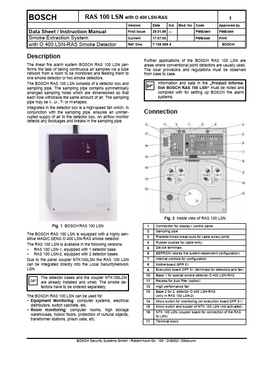
BOSCHRAS 100 LSN with O 400 LSN-RAS1VersionDateInd.Mod. NoCodeApproved byData Sheet / Instruction ManualFirst issue 29.01.99---PMB/dehPMB/deh Smoke Extraction SystemCurrent 17.07.03PMB/zab Print with O 400 LSN-RAS Smoke DetectorRef. Doc. T 138 656 dBOSCH DescriptionThe linear fire alarm system BOSCH RAS 100 LSN per-forms the task of taking continuous air samples via a tubenetwork from a room to be monitored and feeding them to one smoke detector or two smoke detectors.The BOSCH RAS 100 LSN consists of a detector box and sampling pipe. The sampling pipe contains symmetrically arranged sampling holes which are dimensioned so that each hole withdraws the same amount of air. The sampling pipe may be I-, U-, T- or H-shaped.Integrated in the detector box is a high-speed fan which, in conjunction with the sampling pipe, ensures an uninter-rupted supply of air to the detector box. An airflow monitor detects any blockages and breaks in the sampling pipe.Fig. 1 BOSCHRAS 100 LSNThe BOSCH RAS 100 LSN is equipped with a highly sen-sitive MAGIC.SENS O 400 LSN-RAS smoke detector.The RAS 100 LSN is available in the following versions:• RAS 100 LSN-1, equipped with 1 detector base • RAS 100 LSN-2, equipped with 2 detector bases.Due to the panel coupler NTK100LSN the RAS 100 LSN can be integrated directly into the Local SecurityNetwork LSN.The BOSCH RAS 100 LSN can be used for:• Equipment Monitoring: computer systems, electrical distributors, switch cabinets, etc.• Room monitoring: computer rooms, high storage warehouses, hollow floors, protection of cultural objects,transformer stations, prison cells, etc.Further applications of the BOSCH RAS 100 LSN are areas where conventional point detectors are usually used.The local provisions and regulations must be observed from case to case.ConnectionFig. 2 Inside view of RAS 100 LSN1Connection for display-/ control panel 2Sampling pipe3Predetermined break-outs for cable screw joints 4Rubber bushes for cable entry 5Device terminals6EEPROM (stores the system-dependent configuration)7Internal controls for configuration 8Motherboard GPR 519Execution board DFP 51 (terminals for detectors and fan)10Base 1 for special smoke detector O 400 LSN-RAS 11Recess for dust filter (option)12High performance fan13Base 2 for 2. detector O 400 LSN-RAS (only in RAS 100 LSN-2)14Micro switch for monitoring (on execution board DFP 51)15Micro switch and buzzer of NTK 100 LSN (not activated)16NTK 100 LSN (coupler board for connection of the RAS to LSN)17Terminal block2RAS 100 LSNwith O 400 LSN-RASData sheet Copyright by BOSCHDevice connection on GPR 51The electrical connection is via pluggable terminals. Terminal Signal1+ 18 to + 30 VDC20 V3+ 18 to + 30 VDC40 V5+ Supply6Output Fault, St (each events) O-Coll7Output Al 1, O-Coll8Output Al 2, O-Coll9Output St airflow, O-Coll10Fault relay …(a)“Contact (Term. 10 / 12)11Fault relay …(r)“closed in12Fault relay …ra“normal state13Alarm relay 1 …a“14Alarm relay 1 …r“15Alarm relay 1 …ra“16Alarm relay 2 …a“17Alarm relay 2 …r“18Alarm relay 2 …ra“19Input Reset External +20Input Reset External -Terminal assignment for DFP 51The detector bases in the RAS 100 LSN-1 and RAS 100 LSN-2 are wired at the factory according to the following table. Depending on the line technology (loop or tee-off), the corresponding wiring may have to be adapted in the device (see …Product Information BOSCH RAS 100 LSN“, Chapter 7 …Installation“).Te.Connection Wiring1not connected2not connected3bLSN2Detector 1, terminal b1 4Alarm detector 1 Detector 1, terminal c 5not connected6Fan +Fan, red7Fan -Fan, black8Fan tacho Fan, white9not connected10not connected11bLSN2Detector 2, terminal 3 12Alarm detector 2Detector 2, terminal c 13not connectedTerminal assignment for NTK100Te.Connection WiringaLSN2whitebLSN2yellowaLSN1whitebLSN1yellowIII1Ground Central unit, coming III2Ground Central unit, going IV1Power supply +Central unit, redIV2Power supply -Central unit, black VII2Relay fault RAS 100 LSN GPR 51, terminal 10 Terminal assignment for LSN outputs Te.Connection Wiring 1aLSN white 2bLSN yellow Open collector outputsParallel or feedback displays or other consumers can be connected to the open collector (relay).When inductive consumers (e.g. relays) are con-nected, a freewheeling diode must be installed di-rectly next to the consumer. The outputs can be switched to 0 volt and loaded with 100 mA. The outputs are not short-circuit-proof and not potential-free. A con-nection to the outputs affects the total power consumption of the RAS 100 LSN.Fig. 3 Connection of the open collector outputsFor further information and examples, see …Product Infor-mation BOSCH RAS 100 LSN“, Chapter 7, …Installation“.Data sheet Copyright by BOSCHRAS 100 LSNwith O 400 LSN-RAS3Connection drawing for RAS 100LSN-1Connection drawing for RAS 100LSN-2ConfigurationDifferent system-specific configurations can be pro-grammed using the rotary switch, the pushbuttons and the 7-segment indicator on the GPR 51.The configurations are divided into main functions and sub-functions.The selected function is displayed as follows on the 7-segment indicator:•Main functions Number/digit with point •Sub-functions Number/digit without point The key is used for changing from a selected main func-tion to the associated sub-function level and for confirming a changed sub-function.Valid from SW Version 01.02.00ÐMain function (callable by rotary switch position F on motherboard GPR 51)ÐSub-functionMeaning Purpose 4 Device type:0 1 det, foreign brand1 2 det, foreign brand2RAS 100 LSN-1 1 det, BOSCH O 400 LSN-RAS 3RAS 100 LSN-2 2 det, BOSCH O 400 LSN-RAS4 1 det, foreign brand5 2 det, foreign brand 7 Airflow monitoring window:Units:0Window size 0 (small)± 301Window size 1± 402Window size 2± 503Window size 3± 754Window size 4± 1005Window size 5± 1256Window size 6± 1507Window size 7± 2008Window size 8± 4009Window size 9± 600A Window size 10 (large)± 8008 Airflow monitoring On/Off:0Tube break and blockage off1Tube break and blockage on2Tube break off3Blockage off 9 Airflow monitoring delay:0No delay 1Delay 100 sec 2Delay 5 min 3Delay 10 min 4Delay 30 min 5Delay 60 min F Configuration: Display of the set configuration:Main function= static with pointSub-function= flashing without point grey background = Standard configuration IndicationsIndicator and control panelOn the indicator and control panel, four LEDs show theflashes 2x /2x off for 1 min2) No fault triggered (triggers only after expiry of the delaytime Î continuous display).Indications on the motherboard GPR 51 The 7-segment indicator on the GPR 51 may have the fol-lowing indications, depending on the operating state:E briefly = Initialization / HW test–continuous = Unauthorized switch positionflashing = Watchdog indication (= normal mode)In the switch positions …B“ …C“, …E“ and …F“ (+ pressing a key), the following information will be displayed:B Reference value of the airflow (commissioning value).C Actual value of the airflow (actual value).E Error code of any fault present.F Set configuration.The indication of the airflow values (B and C) and the error code (E) happen according to Fig. 4in the form of 4 and 3 numbers in succession.B. /C. / E.100-er10-er1-er EndFig. 4 Display of the airflow values and the error code The configuration currently set is displayed according to Fig. 5. The number sequence appearing on the 7-seg-ment indicator has the following meaning:•Main function Number/digit static with point •Sub-function Number/digit flashing without pointonfigurationisplaymodeevicetype"SD515-1,1detector,anufacturer'sbrand"etectoronitoring"n"larminputs"sdelayed,lf-holding"Smonitoringwindow"indowsize5"Smonitoringelay"sec"ault"elf-holding"ndSmonitoringn/off"ubebreakndblockageon"Fig. 5 Display of the standard configuration (example)Data sheet Copyright by BOSCHRAS 100 LSNwith O 400 LSN-RAS6CommissioningDuring the commissioning of the RAS 100 LSN, an initial reset is required for entering the basic data (e.g. con-nected sampling pipe, motor data). The initial reset also initiates an automatic matching of the airflow monitoring with the connected sampling pipe.Required changes to airflow monitoring should be made after initial reset (system-specific; main function 7 to 9 ) An initial reset causes the configurations always tobe set to the standard configurations associated withthe chosen device type (system-specific configura-tions are discarded).Attention alignment correction (from softwareversion 01.03.00): The RAS 100 LSN performs anautomatic correction of the air flow monitoring 30min,1 h and 18 h after the initial reset. That the ASD will not correct itself on wrong prevailing conditions, there should be done no work with ASD during the alignment conditions like commissioning or function tests.On the control panel, the commissioning sequences are shown as follows:LED …Operation“ (green) = flashes during configuration LEDs …Fault“ + …Operation“ = flash during initial reset LED …Fault“ (yellow) = flashes (2x flashing/2x off) for 1min during alignment correction.StartupBefore the RAS 100 LSN is switched on for the first time, the selection of the device type must be made by means of the rotary switch on the motherboard. The following device types are possible:“2”RAS 100 LSN with 1 detector, O 400 LSN-RAS “3”RAS 100 LSN with 2 detectors, O 400 LSN-RAS When the supply voltage is applied while simultaneously depressing the input key on the GPR 51, the set device type, including the associated configurations, is then automatically loaded (with …2“ and …3“ = standard configu-ration). In addition, the …Initial reset“ procedure is started (0 flashing).Sequence, procedure:a) Device is in the voltage-free state, terminals 1 / 2 dis-connectedb) Select device type with rotary switch (…2“ or …3“)c) Keep button depressed and at the same time switch onASD (connect terminals 1 / 2)d) Do not release button until the number of the selecteddevice type appearse) After the button has been released, 0 begins to flashÎ device type has been loaded, initial reset running. f) After approx. 5 - 6 min the display changes on 1flashing or − static Î the …initial reset“ is finished.g) Switch in position …1“ and press key Î display 1static, after 10s flashing (= normal mode)h) The RAS 100 LSN performs an alignment correctionthree times (30 min, 1h and 18h after the initial reset).Commissioning after extensionsAfter changes of the pipe network due to extensions or reparation an “Initial reset” procedure has to be carried out by the main function “0”. For that choose the rotary switch position “0” and keep the key depressed for approx. 10s during the RAS 100 LSN is in normal operation ( flashing, watchdog). 0 flashing indicates that the initial reset is running.Attention: Device-specific configurations are deleted.The procedure of commissioning sequence is listed below (also see …Product Information BOSCH RAS 100 LSN, Chapter 7.7. …Commissioning“).Use as RAS 100 LSN-1, with standard configuration (Example)Measure DisplayProcessNote(1) Sampling pipe must have been checked for correct installa-tion (connection points, sampling holes). The smoke de-tector or detectors must be inserted and the cover of theÎContinued to (6) or (18)7 RAS 100 LSNwith O 400 LSN-RASData sheetCopyright by BOSCHChange of standard configurationExample of change of airflow monitoring to:…Window size 2, delay 5 min“.MeasureDisplayProcess NoteBefore the standard configuration can be changed, the selectionof the device type and an initial reset must have been performed(18) Attention!! Automatical alignment cor-rection after 30 min, 1h and 18h. Operations from point (18) notcarrying out during alignment correction (LED …Fault“ flashes 2x).Output of the commissioning valuesioning after a timeout of 5 min. = fault)Measurements/ Commissioning protocolThe following measurements must be performed:• Voltage at ter. 1 (+), 2 (-) Î setpoint = 24 to 28 VDC • Airflow value in the switch position …B“ and …C“ (+ keydepressed)• Configuration in the switch position …F“ (+ key de-pressed)The airflow values and the configuration are displayed on the 7-segment indicator according to …Indications on the motherboard“. The results of the measurement should be entered in the attached commissioning protocols.The airflow values of the commissioning (position …B“ and …C“) and the configuration (position …F“) should also be recorded on the attached commissioning sticker. This sticker should then be stuck inside the cover of the elec-tronics chamber.Only the values of the 1st commissioning should be entered on the commissioning sticker (correc-tion after waiting for 1 h). If an initial reset is re-quired after maintenance work on the tube network (cleaning of the sampling holes, replacement of the dust filter), the values …B“ and …C“ should be entered only in the commissioning protocol.The entry on the commissioning sticker may be changed only after:• Initial reset, owing to changes to the sampling pipe(extension/conversion),• Initial reset, owing to replacement of fan or mother-board GPR 51.The protocol is a sort of curriculum vitae of the RAS 100LSN. The commissioning protocol must be filled in consci-entiously and completely and then returned to the elec-tronics chamber. If necessary, a copy may be filed in the systems file.Checking of fault and alarm triggering Triggering of fault and alarm on the RAS 100 LSN after removal of the cover of the detector chamber. Checking for correct alarm transmission (zone/line) to FACP.Block or switch off fire control installation remotealarm to superior FACP.Attention!! Automatical alignment correction after 30 min, 1h and 18h (LED …Fault“ flashes 2x). Following operations not carrying out during the alignment correc-tion.Test event Procedure ActionCover monitoring Open detectorchamber cover• Fault LED flashes• After expiry of the airflowdelay, ASD triggers fault Îfault to FACP ➀Detector moni-toring •After fault re-set of preced-ing test presscover tamperinside detectorchamber im-mediately•Remove de-tector• RAS 100 LSN triggers faultÎ fault to FACP ➀ / ➁• With connection accordingfrom FACP line Î ASDtriggers no fault Î fault di-rectly to FACP ➀ / ➁Test alarm Spray detectorwith test gas • RAS 100 LSN triggers alarm Î Alarm to FACP ➀/ ➁➀The RAS 100 LSN must be reset between the individ-ual controls (preferably at the FACP, as a reset at the RAS 100 LSN does not reset the FACP).➁If two detectors are provided (RAS 100 LSN-2), the control has to be carried out individually for both de-tectors.After completion of the controls, the detector chamber has to be closed again.After the end of all commissioning work, the rotaryswitch position …1“ must be set on the RAS 100LSN (pos. for normal mode). The RAS 100 LSN may be left only in the state of the watchdog display - flashing point of the 7-segment indicator. (Otherwise incomplete commissioning and trigger a fault after a timeout of 5 min = Fault).Article numbers / Spare partsBrief description ID-Nr: Bosch Art. No.SECURITON BOSCH RAS 100 LSN-1 4.998.030.987BOSCH RAS 100 LSN-2 4.998.030.991Smoke det. O 400 LSN-RAS 4.998.115.986Motherboard GPR 51115.215317 Lead-through board DFP 51115.215325 Indication a. Control Board BAP 51115.215333 Fan035.209732 Cable screw union PG 11428.187046 Cable screw union PG 13.5428.205737 Lock nut PG 11428.015245 Lock nut PG 13.5428.162116 Dust filter (option)022.212458 Dust filter box (option)from manufacturer on request Product InformationRAS 100 LSN4.998.121.289 Commissioning protocol T 139 121Dimensioned drawingchamberDetectorchamberConnect. for samplingAir outlet (connectionfor sampling piperecycling, optional) Fig. 3 Detector box BOSCH RAS 100 LSNTechnical DataType RAS 100 LSN Supply voltage range18 to 30 V DC Current consumption max. at:24 V DCNormal / Fault approx. 280 mAAlarm 1 + 2approx. 280 mA Switch-on current peak (caused by FACP protective elements on ASD supply input)for max. 1 ms approx. 5 A Sampling pipe (length, dimensions, holes, etc.)See …Product Information BOSCH RAS 100 LSN, Chapter 3 …Planning“Response range of the O 400 LSN-RAS0,02 ... 0,03 dB/m Protection according to IEC 529 / EN 6052953 IP Ambient conditions according to IEC 721-3-3 / EN 60721-3-3 (1995)Class 3K5 / 3Z1 Extended ambient conditions:Temperature range of detector box0 - +50 °CTemperature range of sampling pipe cAmbient humidity of detector box (briefly without thawing) c≤ 95%Ambient humidity (continuous)≤ 70% Max. load capacity of relay contact50 V DC/ 1 A/ 30 W Pluggable terminals1,5 mm²Cable entry for cableØØ 6 - 9 (- 12 d) mm Housing material ABS-Blend, UL 94-V0 Housing colour grey RAL 2807/ anthracite-violet RAL 3002 Approval (EN 54) VdS ID number G 299 093 Dimensions (W x H x D)285 x 360 x 126 mm Weight2700 gcUse in thawing range only after consultation with the manufacturer.d When cable screw unions PG 13.5 are used.。
PointGrey灰点相机使用说明书

2019/5/13
安装相机采集软件
9.出现以下对话框后,点击“Next”直接下一步。
22
2019/5/13
中国最大机器视觉光源解决方案供应商
世界级光源企业
安装相机采集软件
10.出现以下对话框后,选择安装在哪个盘,然后点击“Next”直接下一步。 电脑一般默认装在C盘里面。
23
2019/5/13
硬件装置联接
3.主板上有两条PCI插槽,在安装1394卡前选好任意一条卡槽后再将对应机箱后 面的档板用螺丝刀撬开。下图档板是已撬开后的画面。
(档板位置)
8
2019/5/13
硬件装置联接
4.用螺丝刀将机箱后面档板上的螺丝卸掉,好便于把卡插进去。
9
2019/5/13
硬件装置联接
5.用手拿着1394卡双手握住卡的两端将金手指方向对准卡槽,然后将1394采集 卡插入到主板上的PCI插槽中,注意力度,以垂直的方向向下慢慢按,感觉插到 头了再也插不进去的时候就表示安装到位了。(注意,插不进千万不要用蛮力, 不然很容易按坏主板的,一定要对准了位置以垂直的方向插入,而且两头用力要 均匀,这样才能确保金手指完全插进去。)
29
2019/5/13
中国最大机器视觉光源解决方案供应商
世界级光源企业
安装相机采集软件
17.弹出以下相机表示相机安装运行顺利成功。
30
2019/5/13
中国最大机器视觉光源解决方案供应商
世界级光源企业
相机驱动转换成微软模式方法
1.用鼠标双击下面的DriverControlGUI图标打开驱动模式对话框。
3
2019/5/13
中国最大机器视觉光源解决方案供应商
- 1、下载文档前请自行甄别文档内容的完整性,平台不提供额外的编辑、内容补充、找答案等附加服务。
- 2、"仅部分预览"的文档,不可在线预览部分如存在完整性等问题,可反馈申请退款(可完整预览的文档不适用该条件!)。
- 3、如文档侵犯您的权益,请联系客服反馈,我们会尽快为您处理(人工客服工作时间:9:00-18:30)。
技 术
1.3 MP TBD
CM3-U3-28S4
Sony ICX818
1/1.8”
2.8 MP
TBD
3.69 µm
两种均有
$595 / € 449
Apr 2015
凌
云
光
低成本,多功能,超紧凑型
• 有USB3 Vision®和GigE Vision®接口供选择 • 最小的 GigE Vision POE相机: 29x29x 30mm • 超轻的机械设计,重量仅36克
技 术
CM3-U3-13S2M-CS
44 x 35 x 19.5 mm
光
标准相机
板卡级 CS mount
CM3-U3-13S2M-CS-BL 39 x 30 x 12.5 mm
板卡级 M12 mount
远程头 CS mount
远程头 M12 mount
CM3-U3-13S2M-M12-RH*
* Availability TBC
凌
云
光
技 术
GigE Vision,USB3 Vision标准兼容
3D 立体视觉相机
Bumblebee相机是移到导航,医疗图像,器件抓取,人体跟踪等 应用的理想选择 可选镜头焦段,2.5到5毫米 带GPIO做外部触发,频闪灯控制
的重新校准
凌
立体处理SDK提供实时的3D深度数据
云
多种外观选择
封装型相机采用金属外壳
封装型相机很容易转换成板卡级相机
凌
云
在远程头中,图像板卡和主机板通过 线缆分开
光
还可提供S-mount (M12 mount) 微透镜 接口
技 术
板卡级相机提供CS镜头接口
应用
Chameleon3灵活的外观形式,使其能适用于众多不同的应用。
技 术 光
云
光
何以与众不同?
技 术
亮点: 尺寸和重量 横截面尺寸仅为29mm×29mm , 适用于各种系统 最接近的GigE竞争产品比其长 11mm 重量仅36克
凌
云
光
是半导体和电子仪器、无人机、头 戴式系统和手持设备的理想之选
技 术
亮点:功耗
更小的功耗、更少的散热,有助于成像系统的图像质量和 热管理 功耗小于2.5 W 能通过GPIO连接器供电
凌
Point Grey 最新产品介绍 USB 3.0和GigE相机
Point Grey 中国成像专家研讨会 2015年8月
云
光
技 术
标准成像产品
CCD和CMOS传感器,30万到9百万画素,1/4”到1”光学尺寸 所有型号提供通用I/O口提供外部设备同步(触发,频闪灯,串口) 图像处理核(彩色变换,查找表, Gamma,锐化等) FlyCapture SDK license (Win/Linux, x86/x64) 主要型号提供3年质保
FireWire (LD3)或USB 3.0 (LD5) 接口
凌
Ladybug SDK 提供实时的全景图像拼接
云
光
技 术
凌 云 光
技 术
配件
封装型与板卡级相机
• 板卡级USB3 Vision®相机 • 面向空间受限的低成本应用 • 三种外观样式选择
云 凌
光
• 不同的安装选择 • 丰富的 CCD & CMOS传感器 • 卓越的价值
凌
金属外壳封装,带有螺 板卡级相机,带有CS镜头 板卡级相机,带有M12 带状头配置,带有CS镜头 带状头配置,带有M12镜 旋锁紧接口连接器和CS 镜头安装口 安装口 头安装口 安装口 镜头安装口
云
CM3-U3-13S2M-M12-BL* 39 x 30 x 12.5 mm
CM3-U3-13S2M-CS-RH*
云 凌
光
• • 各种各样的 CCD & CMOS 传感器 低功耗 (< 2.5 W) 使产生的热量最小化
技 术
•
•
LED用于状态显示
传感器前配备防护玻璃
• 相机上的帧缓存器使得图像丢失或图像损坏最小化为用户数据提供闪存
• 价格低于其他解决方案超过30%
• 提供行业领先的3年质保期
凌
• 基于FPGA的图像处理机制,能够实现色彩转换、伽玛校正、查找表、自动曝光等
电源 光输入 NC / +3.3 Vபைடு நூலகம்输出 光 GND GND
说明
+12 V DC相机电源 光隔输入 固件控制的+3.3 V输出。电流 限制。 光隔输出 光隔 I/O地,与相机地不相连 DC相机电源地
医疗与生命科学
眼球跟踪 显微镜学
工业
3D 扫描便携设备
低成本自动化检测系统
交通与安全
低成本OEM 解决方案采用嵌入式板卡级 产品
凌
云
Chameleon3 USB 3.0相机
传感器类型 CM3-U3-13S2 CM3-U3-13S2-BD CM3-U3-13Y3 全局快门 CCD 全局快门 CCD 全局快门 CCD 全局快门 CCD 传感器型号 Sony ICX445 Sony ICX445 On Semi Python 1300 尺寸 1/3” 1/3” 1/2” 像素 1.3 MP 1.3 MP 最大帧率 像素尺寸 彩色/黑白 30 30 3.75 µm 3.75 µm 4.8 µm 两种均有 两种均有 两种均有 价格 ($USD/€) $295 / € 219 $295/€219 (MOQ10) $350 / € 269 发布时间 Jan 2015 Feb 2015 June 2015
不需要现场校正和使用中
光
预校正以解决扭曲及错位,
技 术
30万,80万,130万像素,IEEE-1394 Firewire接口
360 度全景相机
Ladybug相机集成6个高品质Sony CCD(5环绕,1个顶部)
提供RAW和JPEG压缩图像码流
防水工业外壳 预校正以解决扭曲及错位, 不需要现场校正
技 术
• 相机上的帧缓存器最大程度地减少了图像丢失或损坏;闪存用于用户数据。
• 固件可现场升级。
• 为封装型相机和板卡级相机提供业界领先的三年质保期。
凌
• 基于FPGA的图像处理机制,用于色彩转换、伽玛校正、查找表和自动曝光等。
云
光
何以与众不同?
技 术
5种模块选择
Chameleon3灵活的外观形式,使其能适用于众多不同的应用。
类似规格的竞争产品的功耗超过3 W
凌
功耗 热量
云
光
质量
技 术
亮点: GPIO
Blackfly遵循通用GPIO配置 1 路光隔输入 1 路光隔输出
6针Hirose连接器
凌
• Blackfly能够通过简单的插拔, 很容易地替代市场上很多管 脚兼容的相机
云
光
图解 管脚
1 2 3 4 5 6
技 术
功能