MATLAB Hybrid simulation platform
基于MATLAB的AM、DSB系统仿真

河南科技Henan Science and Technology总708期第十期2020年4月工业技术基于MATLAB 的AM.DSB 系统仿真白皓文林君(延边大学通信工程(中外合作办学)专业,吉林延吉133002)摘要:AM.DSB 调制是通信系统中最重要的、最基础的调制之一。
本文首先分析了 AM 、DSB 调制的原理,然 后运用MATLAB 仿真平台设计了这两种调制的仿真模型。
通过仿真,观察了 AM.DSB 信号调制过程中各环节的时域和频域波形。
最后,在仿真基础上分析比较了这两种调制方式的性能。
关键词:MATLAB ;调制方式:AM ;DSB 中图分类号:TN911.3文献标识码:A文章编号:1003-5168( 2020) 10-OO38-O3MATLAB Based AM, DSB System SimulationBAI Haowen LIN Jun(Communication Engineering (Sino-Foreign Cooperative Education) Major of Yanbian University ,Yanji Jilin 133002)Abstract : AM modulation and DSB modulation is one of the most important and fundamental modulation in communi cation system. This paper first analyzed the principle of AM modulation and DSB modulation, then used MATLAB simulation platform to design the two kinds of modulation simulation model. The time domain and frequency domainwaveforms of AM and DSB signal modulation were observed by simulation. Finally, the performances of the two modu ・ lation modes were compared on the basis of simulation.Keywords : MATLAB ; modulation mode ; AM ; DSB通信系统中包含两种调制方式,即模拟调制方式和 数字调制方式。
外文翻译+原文
MATALAB 混合仿真平台控制算法的概述MATALB混合仿真平台,即为将硬件引入到仿真回路里的半实物仿真系统,可用于过程控制器的开发与测试。
平台提供了三种控制器的嵌入方法,尤其能用Matlab 语言编写,大大提高了平台的灵活性。
为了建立过程控制混合仿真试验系统,必须解决PC 机作为虚拟控制器设计环境的实现和在Windows 操作系统中实时控制的实现这两个问题。
我们先详细阐述过程控制混合仿真试验系统的实现原理;最后介绍平台控制算法的嵌入方法,并通过实验仿真验证平台的有效性。
过程控制混合仿真平台实现原理:(1)数值计算,MATLAB提供了大约600多个数学和工程上常用的函数。
这些函数的数值运算是针对矩阵操作优化过的,可以使用它来代替底层编程语言。
在保持同样性能的情况下,编程工作量非常小,数值计算采用了LAPACK,BLAS,FFTW等优秀数学函数库,使得计算效率得到进一步的提升。
MATLAB 包含的主要数学函数有线性代数和矩阵运算、傅立叶变换和统计分析、微分方程求解、稀疏矩阵运算以及三角和其他初等数学运算等;除此之外,随着Matlab的应用领域不断的扩大,补充了用于许多特定领域的函数。
(2)算法开发,强大的计算能力,方便易用的编程语言和丰富的数学函数使MATLAB最适于用于算法开发工作。
典型的应用包括:数据分析,信号处理,图像处理,系统建模和高级算法研究等。
不管用户是使用已有的算法,还是自行开发,MATLAB提供了一个通用的平台。
使用MATLAB进行算法开发就像平时书写数学表达式一样。
将用户在MATLAB 中开发的算法结合到外部运行的系统中。
一旦用户的算法和仿真经过了编写和调试,MATLAB Compiler和C/C++ Math Library 会将MATLAB应用自动转换成可移植C 和C++代码的工具。
对于信号处理,控制系统设计和其他一些应用,MATLAB工具箱提供了一系列先进的技术。
工具箱远远超出了提供一些基本算法的范畴:他们提供了一个学习,研究,创新前沿理论和技术的舞台。
PLECS 与MATLAB联合仿真实例
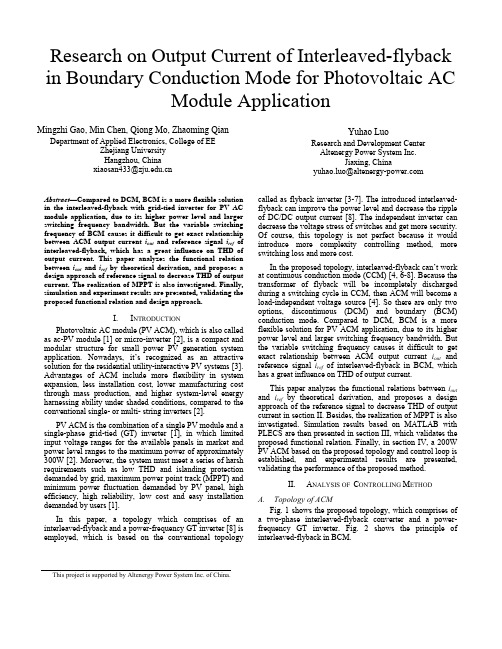
Topology of ACM Fig. 1 shows the proposed topology, which comprises of a two-phase interleaved-flyback converter and a powerfrequency GT inverter. Fig. 2 shows the principle of interleaved-flyback in BCM.
I.
INTRODUCTION
Photovoltaic AC module (PV ACM), which is also called as ac-PV module [1] or micro-inverter [2], is a compact and modular structure for small power PV generation system application. Nowadays, it’s recognized as an attractive solution for the residential utility-interactive PV systems [3]. Advantages of ACM include more flexibility in system expansion, less installation cost, lower manufacturing cost through mass production, and higher system-level energy harnessing ability under shaded conditions, compared to the conventional single- or multi- string inverters [2]. PV ACM is the combination of a single PV module and a single-phase grid-tied (GT) inverter [1], in which limited input voltage ranges for the available panels in market and power level ranges to the maximum power of approximately 300W [2]. Moreover, the system must meet a series of harsh requirements such as low THD and islanding protection demanded by grid, maximum power point track (MPPT) and minimum power fluctuation demanded by PV panel, high efficiency, high reliability, low cost and easy installation demanded by users [1]. In this paper, a topology which comprises of an interleaved-flyback and a power-frequency GT inverter [8] is employed, which is based on the conventional topology
MATLAB7.0使用详解-第9章 SIMULINK交互式仿真集成环境
9.5.2 模型的仿真过程
SIMULINK的仿真就是在用户指定的时间段内按照模型提供的初始条件,按 照一定的流程计算系统的状态变化和输出的过程。包括两个执行阶段:初 始化阶段和动态计算阶段。 1.初始化 模型仿真在初始化阶段主要需要完成以下工作。 (1)确定模块计算的实际参数,主要通过评估模型参数得到。 (2)展开模型的继承关系。每个子系统用其所包含的模块代替。 (3)确立模块运行的次序。 (4)确定模型中非显式设置信号的属性,如名称、数据类型等。并检查 每个模块是否能够接收到连接它们输入端的信号。 (5)确定模块的采样时间。 (6)分配和初始化存储每个模块状态值和输出当前值的存储空间。 2.动态计算阶段 一般的仿真模型都是通过数值积分来计算的。在仿真的时间段里, SIMULINK在每一个时间间隔点都是按顺序计算系统状态和输出值的,这些 计算状态和输出的时间点成为时间步长,相邻两个时间点间的长度称为步 长,步长的大小取决于求解器的类型。在每个时间步长里,SIMULINK计算 系统输入、状态和输出,并更新模型来反映计算出的值。
第9章 SIMULINK交互式仿真集成环境
SIMULINK是基于MATLAB的图形化仿真设计环境,是MATLAB 提供的进行动态系统建模、仿真和综合分析的集成软件包。 在SIMULINK环境中,用户可以脱开理论阐述必须进行理想 化假设的无奈,实时了解一些自然因素(如摩擦、风阻等) 以及其他一些随机因素对系统行为的影响。 SIMULINK可以处理的系统包括:线性、非线性系统;离散、 连续及混合系统;单任务、多任务离散事件系统等。 SIMULINK和MATLAB是高度集中在一起的,因此,它们之间 可以进行灵活的交互操作。在MATLAB7.x的版本中,由于有 许多可供直接使用的工具箱和模块,因此它在航天、通信、 控制、信号处理、电力系统等诸多领域都有广泛的用途。
全系统虚拟平台的仿真核心的设计
摘要随着SoC设计的日益复杂,传统的虚拟平台的性能已经无法满足开发者的需求。
业界都在寻找提高虚拟平台的性能的有效办法。
随着虚拟化技术的发展,以QEMU为代表的高性能模拟器被开发出来,给提高虚拟平台性能提供了新的途径。
但是模拟器相对传统虚拟平台有一定缺陷:模拟器难以精确描述模块的时序关系。
为了在保证传统虚拟平台的优势情况下并提高性能,本文提出了一种将传统虚拟平台仿真核心和模拟器仿真核心集成的方法,设计了新的仿真核心并以此搭建了全系统虚拟平台HVP(Hybrid Virtual Platform)。
本文以成熟的QEMU模拟器和SoCRocket虚拟平台为基础,进行了二者仿真核心的集成,从而搭建了新的HVP选系统虚拟平台。
在设计过程中,首先确定了QEMU嵌入SystemC仿真核心的总体架构。
根据总体架构将需要完成的工作划分为三个主要模块和四个必要的运行机制。
并且利用P线程技术完成了QEMU和SystemC仿真核心多个线程的划分。
其次为了QEMU和SystemC两个仿真核心可以正常的同步和通信,HVP平台使用了基于量子的时间同步策略,以时间量子为单位进行时间同步。
根据TLM2.0 Sokcet原理,为QEMU和SystemC两个仿真核心设计了用来传输事务的Socket和传输函数。
并设计了一个线程安全的事件,保证了事务传输的线程安全。
在完成仿真核心集成后,通过DMI接口和QEMU内存建模方法重新设计了指令执行机制,并根据SystemC仿真核心的启动阶段设计了新的启动机制,保证了QEMU和SystemC两个仿真核心可以协同启动并运行。
最后对HVP平台进行了相关的测试和验证,包括基准测试程序验证、性能测试、IO访问测试和IO中断测试等。
展示了新的仿真核心性能上的优越性。
并证明了HVP 平台的IO访问和IO中断可以正确有效的执行。
关键词:QEMU;SoCRocket;TLM2.0;全系统虚拟平台AbstractWith the SoC design increasingly complex, the performance of traditional virtual platform is hard to meet the needs of developers. The industry is looking for an effective way to improve the performance of virtual platforms. With the development of virtualization technology, QEMU as the representative of the high-performance simulator was developed to improve the performance of virtual platform provides a new way. But the simulator has some flaws relative to traditional virtual platforms: it is difficult for the simulator to accurately describe the timing of the module. In order to ensure the advantages of traditional virtual platform and improve performance, this paper presents a traditional virtual platform simulation core and simulator simulation core integration method, designed a new simulation core and to build a full system virtual platform HVP(Hybrid Virtual Platform ) The HVP platform is based on the integration of SystemC and SoCRocket. The HVP platform not only has the characteristics of traditional virtual platform, but also make simulation core performance greatly improve to meet the needs of the subject. In this paper,through the research and related technical research of the related literature, the whole architecture of the HVP platform is determined. And we have studied the principle and technology of QEMU and SoCRocket platform in-depth.Secondly, in order to synchronize and communicate with QEMU and SystemC, we designed the time synchronization mechanism and the transaction mechanism based on TLM2.0 specification for HVP.And in order to ensure that QEMU and SystemC simulation core can effectively co-simulate and complete the operation of the program. We redesigned the instruction execution mechanism and start mechanism.Finally, we do the test of the HVP platform including performance test, IO access test and IO interrupt test. Demonstrating the superiority of the new simulation core performance. And proved that the HVP platform IO access and IO interrupt can be implemented correctly and effectively.Keywords: QEMU; SoCRocket; TLM2.0; Full system virtual platform目录摘要 (I)Abstract (II)第1章绪论 (1)1.1 课题背景及研究意义 (1)1.2 国内外研究现状 (4)1.2.1 SystemC与TLM-2.0事务级建模 (4)1.2.2 模拟器技术研究现状 (7)1.2.3 仿真核心集成技术研究现状 (9)1.3 课题主要研究内容 (12)1.4 论文结构 (13)第2章HVP平台总体架构的设计 (14)2.1 HVP平台总体架构 (14)2.1.1 HVP平台总体架构的确立 (14)2.1.2 实现仿真核心集成的关键模块 (15)2.2 SoCRocket虚拟平台分析 (17)2.3 QEMU模拟器分析 (18)2.4 本章小结 (21)第3章HVP平台的时间同步机制和事务传输机制 (22)3.1 HVP平台的时间同步机制 (22)3.1.1 时间同步机制的确定 (22)3.1.2 基于量子的时间同步原理 (24)3.1.3 量子同步机制的实现 (25)3.2 HVP平台的事务传输机制 (28)3.2.1 TLM2.0 Socket机制 (28)3.2.2 事务传输机制的实现 (29)3.3 本章小结 (33)第4章HVP平台的指令执行机制和启动机制 (34)4.1 HVP平台的指令执行机制 (34)4.1.1 TLM2.0的DMI接口 (34)4.1.2 QEMU的内存虚拟化 (35)4.1.3 QEMU动态翻译和指令执行过程 (37)4.1.4 HVP平台的指令执行机制的实现 (39)4.2 HVP平台的启动机制 (41)4.2.1 SystemC内核仿真阶段 (41)4.2.2 HVP平台启动机制的实现 (42)4.3 本章小结 (43)第5章HVP平台的验证和测试 (44)5.1 HVP平台的功能验证 (44)5.1.1 Mibench基准测试程序验证 (44)5.1.2 Dhrystone基准测试程序验证 (45)5.2 HVP平台的性能测试 (45)5.2.1 HVP平台不同量子情况下的性能测试 (45)5.2.2 HVP平台标准性能测试 (46)5.3 HVP平台IO访问和IO中断的测试 (47)5.4 本章小结 (49)结论 (50)参考文献 (51)攻读硕士学位期间发表的论文及其它成果 (55) (56)致谢 (57)第1章绪论1.1 课题背景及研究意义本课题来源于项目“全系统虚拟平台的设计与验证”,课题的总体目标包括:基于QEMU和SystemC仿真核心,完成二者的集成,进而搭建出一个新的全系统虚拟平台HVP;并为HVP平台设计出完善有效的时间同步机制,事务传输机制,指令运行机制和启动机制。
基于Matlab的移相全桥变换器仿真实验平台设计

入输出信号相同即可。所建立的模型可以是程序模块 或基本单元组成的电路模块。
将移相脉冲发生 器 看 作 由 脉 冲 信 号 发 生 器、移 相 信号发生器和死区时间设置3部分组成的一个功能模 块 ,如 图 6 所 示 。 其 中 ,脉 冲 信 号 发 生 器 产 生 频 率 固 定 且占空比为50%的互补方波脉冲 Q 和 QN;移相 信 号 发生器产生相对 于 脉 冲 波 形 Q 和 QN 有 一 定 相 位 差 的互补方波脉冲 Q’和 QN’,此 相 位 差 的 大 小 由 调 节 器的输出决定,小于方波脉冲周期 的 1/2;死 区 时 间 设 置模块分别设置两组互补方波脉冲之间的死区时间。
图2 主电路的 Matlab模型图
主电路中的变压器起着隔离和传输功率的作用, 变 压 器 次 级 与 二 极 管 构 成 全 波 整 流 器 ,如 图 2 所 示 ;滤 波器为常用 的 倒 “L”型 结 构;负 载 由 带 有 跳 变 装 置 的 电阻 Ro1和 Ro2组成。跳变装置 S1和 S2的构成如图3 所 示 ,其 作 用 是 测 试 系 统 在 负 载 变 化 时 的 动 态 响 应 ,使 负载电阻在t=0.01s(该时间值可自行设定)处 从 Ro1 跳变到 Ro2。
图 3 负 载 跳 变 模 块 构 成 图
由于 Matlab仿真工具箱中没有运放模块,故补偿 网络可以采用 PI或 PID 模 块[7-9],或 者 直 接 用 带 有 限 幅 功 能 的 传 递 函 数 模 块 ,如 图 5 所 示 。
2.2 控 制 系 统 模 型 的 建 立 移相全桥变换器的控制系统包含调节器和移相脉
首先利用控制对象传递函数类型选定补偿网络结构然后依据频率特性曲线设定补偿网络的零极点再根据系统开环传递函数频率特性曲线的期望穿越频率调整补偿网络增益就得到了反馈控制中补偿网络的传递函数gcv56表示可以通过设置零极点转化为单零点单极点等其他类型的传递函数表达式
基于AMESim、MATLAB_与LabVIEW_的联合仿真虚拟平台技术
第 22卷第 10期2023年 10月Vol.22 No.10Oct.2023软件导刊Software Guide基于AMESim、MATLAB与LabVIEW的联合仿真虚拟平台技术董壮壮,王兆强,孙令涛,陆阳钧(上海工程技术大学机械与汽车工程学院,上海 201620)摘要:针对AMESim和MATLAB/Simulink的机电液系统联合仿真过程中参数设置较为繁琐、仿真结果可视化效果不够直观等问题,基于FMI标准化接口和ActiveX技术,利用LabVIEW进行人机交互界面设计与数据交互,研究了一种可定制化、参数设置集中化且仿真结果可视化的仿真虚拟平台技术。
初步应用实验结果表明,该虚拟平台可简便地对联合仿真模型进行参数设置与数据交互,结果准确、仿真效果直观,且仿真报告可自动化输出,有利于提高工作效率。
关键词:联合仿真;人机交互;多物理域;虚拟平台;数据交互DOI:10.11907/rjdk.231493开放科学(资源服务)标识码(OSID):中图分类号:TP391.9 文献标识码:A文章编号:1672-7800(2023)010-0042-07Joint Simulation Virtual Platform Technology Based on AMESim,MATLAB and LabVIEWDONG Zhuangzhuang, WANG Zhaoqiang, SUN Lingtao, LU Yangjun(School of Mechanical and Automotive Engineering, Shanghai University of Engineering Science, Shanghai 201620, China)Abstract:In response to the problem of cumbersome parameter settings and insufficient visualization of simulation results in the joint simu⁃lation process of AMESim and MATLAB/Simulink electromechanical hydraulic systems,a customizable,centralized parameter settings,and visualized simulation results simulation virtual platform technology was studied using LabVIEW based on the standardized interface of FMI (Functional Mock up Interface) and ActiveX technology for human-machine interaction interface design and data exchange. The pre⁃liminary application experimental results showed that the virtual platform can easily set parameters and interact with data for joint simula⁃tion models, with accurate results and intuitive simulation effects. The simulation report can be automatically output, which is conducive to improving work efficiency.Key Words:joint simulation; human-computer interaction; multi-physical domain; virtual platform; data interaction0 引言目前,国内外仿真软件种类越来越多,仿真技术已经广泛地应用于汽车制造[1-4]、工程机械[5]、航空航天[6-7]等领域。
matlab 控制系统仿真
摘要MATLAB语言是一种十分有效的工具,能容易地解决在系统仿真及控制系统计算机辅助设计领域的教学与研究中遇到的问题,它可以将使用者从繁琐的底层编程中解放出来,把有限的宝贵时间更多地花在解决科学问题上。
MATLAB GUI 是MATLAB的人机交互界面。
由于GUI本身提供了windows基本控件的支持,并且具有良好的事件驱动机制,同时提供了MATLAB数学库的接口,所以GUI 对于控制系统仿真的平台设计显得十分合适。
GUI对于每个用户窗口生成.fig和.m 文件。
前者负责界面的设计信息,后者负责后台代码的设计。
本文所做的研究主要是基于MATLAB GUI平台,结合控制系统基础理论和MATLAB控制系统工具箱,实现了用于控制系统计算机辅助分析与设计的软件。
本软件主要功能:实现传递函数模型输入、状态方程模型输入、模型装换、控制系统稳定性分析、系统可观性可控性判断,绘制系统奈奎斯特图、波特图、根轨迹图以及零极点分布图。
在继续完善的基础上能够用于本科自动控制原理教程的教学实验和一般的科学研究。
关键词:控制系统;MATLAB GUI;计算机辅助设计AbstractMATLAB language is a very effective tool,and can be easily resolved in the system simulation and control system of teaching in the field of computer-aided design and research problems,it could be the bottom of the user from tedious programming liberate the limited spend more valuable time to solve scientific problems.The MATLAB GUI is the interactive interface.As the GUI itself provides the basic control windows support,and has a good mechanism for event-driven,while providing the MATLAB Math Library interface,the GUI for control system simulation platform for the design of it is suitable. GUI window generated for each user. Fig and.M file. The former is responsible for the design of the interface information,which is responsible for the design of the background code.Research done in this article is mainly based on MATLAB GUI platform,the basis of combination of control system theory and MATLAB Control System Toolbox,the realization of control systems for computer-aided analysis and design software. The main functions of the software: the realization of transfer function model input,the state equation model input,the model fitted for the control system stability analysis,system observability controllability judgments、rendering the system Nyquist diagram、Bode plots、root locus and Pole-zero distribution. While continuing to improve based on the principle of automatic control can be used for undergraduate teaching course experiments and scientific research in general.Key words:Control System;MATLAB GUI; Computer-assistant design目录第1章概述 (1)1.1 论文选题背景和意义 (1)1.2 计算机辅助分析与设计在控制系统仿真中的发展现状 (1)1.3 本文主要内容 (3)第2章控制系统与MATLAB语言 (4)2.1 控制系统理论基础 (4)2.2 MATLAB语言与控制系统工具箱 (5)第3章 MATLAB GUI简介及应用 (9)3.1 MATLAB GUI (9)3.2 软件设计步骤 (10)第4章仿真系统测试与演示 (16)4.1 控制系统的模型输入 (16)4.2 控制系统的稳定性分析 (19)4.3 控制系统可控可观性分析 (20)4.4 控制系统频率响应 (23)4.5 控制系统时域响应 (27)4.6 控制系统根轨迹绘制 (28)结论 (31)参考文献 (32)致谢 (33)第1章概述1.1 论文选题背景和意义自动控制原理是自动控制专业和自动化专业的主要课程之一,是研究自动控制技术的基础理论课,是必修的专业基础课程。
制造业常用词汇集锦
ERP:ERP=Enterprise Resource Planning 企业资源规划WM= Warehouse Management System 仓库管理系统(不同于ERP中的库存管理)ETO = Engineering-to-Order面向订单设计MTO= Make-to-Order面向订单生产ATO= Assembly-to-Order面向订单装配MTS= Make-to-Stock面向库存生产PP= Production Planning生产计划大纲CO= Controlling控制MPS= The Master Production Schedule主生产排程RCCP= Rough Cut Capacity Planning粗能力需求计划CRP= Capacity Requirements Planning能力需求计划BOM= Bill Of Material物料清单MRP= Material Requirements Planning物料需求计划PAC= Production Activity Control 车间作业管理SD=Sales and Distribution 分销管理MM=Material Management 物料管理MTL=Material Management 物料管理ATP= Available To Promise可承诺产品数量COE= Customer order Entry客户订单输入PO= Purchasing Order采购定单OM= Order Management订单管理IM= Inventory Management库存管理VMI= vendor managed inventory供应商管理库存MRP=Material Requirements Planning 物料需求计划MRPII=Manufacture Resource planning 制造资源规划JIT=Just In Time 及时生产TQM=Total Quality Management 全面质量管理DRP=Distribution Resource Planning 分销资源计划SCM=Supply Chain Management 供应链管理SRM=Supplier Relationship Management 供应商关系管理CRM=Customer Relationship Managemen 客户关系管理BPR=Business Process Reengineering 业务流程重组(再造)EAM=Enterprise Asset Management 企业资产维护/管理WMS=Warehouse Management System 仓库管理系统CDC=Central Distribution Center 中央配送中心RDC=Regional distribution center 区域配送中心RFID=Radio Frequency Identification 无线射频识别(采用无线方式的标签识别技术) Bar Code条形码标签识别技术OA=Office Automation 办公自动化KM=Knowledge Management 知识管理BI=Business Intelligence 商务智能HR=Human Resources 人力资源计划KPI=Key Performance Index 关键绩效指标CRP(Capacity Requirements Planning)产能需求规划DRP(Distribution Resource Planning)分销资源规划visibility--可视化usability--可用性flexibility--灵活性localization--本土化configurable--可配置的customized--定制reporting framework--报表框架drill down--钻取fields--字段On premise--传统应用模式/预置模式On demand--按需配置模式a portal for a large customer’s tracking, receipt, shipments or demand--一个有关大型客户的跟单、收货、出货或需求的门户screens--窗口The key trend is to have smaller and smaller laws and more and more 最主要的趋势是固化的东西越来越少,可配置性越来越强。
网络控制系统仿真平台的研究
网络控制系统仿真平台的研究作者:张芳吴斌季晓静杨智慧来源:《现代电子技术》2008年第06期摘要:网络控制系统(Networked Control Systems,NCS)是计算机控制系统发展的趋势,对于他的研究必须建立在仿真平台的基础上。
介绍网络控制系统仿真平台建立的几种方法,包括利用Truetime工具箱进行仿真,VC和Matlab通过引擎方式进行仿真和DLL方式进行混合编程方式,以上3种方法经过初步验证是可以实现的。
通过分析他们在应用范围方面的不同,指出应该根据研究的需要选择合适的方法。
关键词:网络控制系统;Truetime;C++与Matlab混合编程;仿真平台中图分类号:TP393 文献标识码:A文章编号:1004-373X(2008)06-090-03Study on the Simulation Platform of Network Control SystemZHANG Fang,WU Bin,JI Xiaojing,YANG Zhihui(School of Mechanical Electronic and Control Engineering,Beijing Jiaotong University,Beijing,100044,China)Abstract:Network Control System(NCS) is the development direction of computer control system.To studyit,a platform must be built.in this paper,serveral ways of platform building are introduced,including using Truetime toolbox,using Matlab engine and VC,Matlab and VC DLL programming,the three methods are proved to be usdful.It analyses the differences in application field,and at present,suitable method should be chosen according to demand.Keywords:network control system;Truetime;C++ and Matlab mixed programming;simulation platform1 引言网络控制系统(Network Control System,NCS),又称网络化的控制系统,即在网络环境下实现的控制系统。
- 1、下载文档前请自行甄别文档内容的完整性,平台不提供额外的编辑、内容补充、找答案等附加服务。
- 2、"仅部分预览"的文档,不可在线预览部分如存在完整性等问题,可反馈申请退款(可完整预览的文档不适用该条件!)。
- 3、如文档侵犯您的权益,请联系客服反馈,我们会尽快为您处理(人工客服工作时间:9:00-18:30)。
Hybrid control algorithm MATLAB simulationplatform overviewMATLAB Hybrid simulation platform, that is, the hardware put into the simulation loop in the loop simulation system for process control of the development and testing. Platform embedded controller provides three methods, in particular, can use MATLAB language has greatly enhanced the flexibility of the platform. In order to build simulation system for process control systems must be addressed as a virtual controller PC, the environment and in the Windows operating system to achieve real-time control to achieve these two problems. We first elaborate simulation system for process control system principle, and finally introduced the embedded platform control algorithm method and the experiment results verify the effectiveness of the platform.Hybrid simulation platform process control theory: (1) numerical calculation, based on more than 600 MATLAB provides some commonly used mathematical and engineering functions. The numerical computation of these functions are optimized for matrix operations, you can use it to replace the underlying programming language. Maintain the same performance in the case, the programming effort is very small, value calculated using the LAPACK and BLAS, FFTW other excellent math library, so the calculation efficiency is further improved. MATLAB contains the main mathematical functions are linear algebra and matrix operations, Fourier transform and statistical analysis, solving differential equations, sparse matrix operations, and trigonometric and other elementary mathematics, etc. In addition, use of MATLAB applications with continuous expanded to add a function for a number of specific areas. (2) Algorithm development, computing power, easy to use programming language and rich mathematical functions to the most suitable for MATLAB for algorithm development. Typical applications include: data analysis, signal processing, image processing, system modeling and advanced algorithm research. Whether the user is using the existing algorithms or developing their own, based on MATLAB provides a common platform. MATLAB for algorithm development using the mathematical expression of the same writing as usual User-based algorithms developed in MATLAB integration to external systems running. Once the user'salgorithms and simulation through the writing and debugging, MATLAB compiler and the C / C + + Math Library MATLAB application will be automatically converted to portable ç and C + + code tool. For signal processing, control system design and other applications, MATLAB toolbox providing a range of advanced technology. Toolbox far beyond the scope of provision of some basic algorithms: they provide a learning, research, innovation and cutting-edge theory and technology arena. Algorithm toolbox to provide a neural network toolbox, optimization toolbox, system identification toolbox, robust control toolbox, model predictive control toolbox, the control system toolbox, fuzzy logic toolbox. (3) Data analysis and visualization, through the MATLAB software, users can analyze all types of data, including signal, image, polynomials, time course, data and multi-variable linear systems. From the analysis results can be summed up as a model for the further development of the algorithm and the base. In addition, users can quickly convert the code fragment and knowledge can be reused in automated analysis routines, no variable declarations and the definition of dimension, can write programs quickly. Based on MATLAB provides a convenient data access tools. For example, the data acquisition toolbox allows users to send real-time measurement data directly into MATLAB for analysis, database toolkit to allow users to access consistent with the ODBC and JDBC in the database, while M c and the Fortran language documents and procedures in handling text and binary file I / O function, then allow the user to handle any format. And related MATLAB toolbox contains a scientific computing need of professional graphics. The raw data from the two-dimensional curve to the contour map with markers and interactive graphical user interface, these tools provide a model visualized capabilities to help users understand complex systems. In particular, provides a MATLAB-based three-dimensional scalar and vector visualization capabilities, including display equivalence face and flow diagram. This capability enables scientists and engineers to a large number of complex and multidimensional data visualization.MATLAB real-time simulation environment, RTW is to provide a real-time based on MATLAB other components of the software for seamless connection, not only to meet the designers in the system concept and program design needs, the technology for the system or perform different functions in real-time operating system provides the convenience of experiments, and for implementation of concurrent engineering to create a good environment. It directly from the SIMULINK simulation model produces optimized, portable and personalized code, and automaticallygenerate a variety of configurations depending on the target under the program environment, the hardware running dynamic system model also supports model-based debug.Real-time using the RTW of the design of test hardware, users can shorten the development cycle and reduce costs. When the user model in SIMULINK environment and get satisfactory simulation results, can be a RTW with the goal of rapid prototyping (such as RTWT target) joint use. The goal of rapid prototyping of physical systems and users connected. Users can use the SIMULINK model as the interface to connect the physical target to complete system testing.RTW implementation mechanism is a complex process, where only from the RTW process automated building applications that were analyzed. RTW generated application process diagram (model for the establishment of the SIMULINK name). RTW construction application process by an M-file in order to control for most of the target, the default command is make.rtw.The process is as follows: 1. model, first analyzes the SIMULINK model to analyze the process includes the following main tasks(1) Numerical simulation parameters and molding parameters;(2)Passing the signal width and sampling time;(3) determine the module block diagram of the implementation of the order;(4) Calculation of the size of the vector (mainly for S-Functions module box).In this process, RTW read the model file modle.mdl, and then compile it as a model of internal description. This description is stored in ASCII files and language-independent, name model.rtw. We can use that file as input for the next process, it will be automatically deleted after the code generation.2. call TLC program to generate C code, at this stage, TLC stored in modle.rtw in the internal model description into a specific object code. TLC is an interpreted programming language, programming language design that the only purpose is to model description into the code. TLC in the compilation process of the implementation of multiple object files (TLC script file), and TLC library procedures. Object file is divided into two types: one is the target file system, one is the module object file. The target file to specify how to modle.rtw used as an input, generate code from modle.Real-Time Workshop target binding environment for a variety of target file system, Figure 3.5 shows all the available system target file. In this system, our targetenvironment is windows, the selected target rapid prototyping RTWT, then the building process before, we specify rtwin.tlc as TLC used in the compilation process script file.3.Generate customized M-file, in this step, will have a custom template file (M-file), the file name is model.mk.. Generated makefi1e used to guide the make utility to compile and link model, which generates source code. RTW is a system-generated template (system template M-file) generated modle.mk, this template file name is system.tmf (syetem is the target name is selected), such as in the previous step, we selected rtwin.tlc as Our system target file, also called rtwin.tmf selected our system as a template file. Template file (M-file) allows users to customize the compiler, compiler options and other information during the process to establish, if the compiler used in different, then the makefile file will be different, such as when the target is Windows, the system target file is rtwin . tlc, but with the visual C \ C + + compiler, the system template file is win_vc.tmf, and choose watcom, the system of the template file is win_watc.tmf. molde.mk only system.tmf a copy, you can modify this file to customize the build process of the process.RTWT (Real-Time Windows Target) is to provide and distribute a MATLAB RTW system framework based on the additional products are shipping 将turn its machines into as a PC system with the aim of rapid prototyping one kind of methods for Kong real-time testing and development. In this environment, a PC, both as a host, but also as the target machine there. For RTWT, SIMULINK and the generated code running on the same PC, the interface allows users to run PC-processor running on Windows NT or Windows 95/98/2000/XP operating system, while the code generated by RTW .RTWT supports many types of I / O device boards (including the two types of ISA and PCI). Users only need to install related software, a compiler and I / O device card, a PC machine can be used for real-time system and through I / O devices and external devices to connect. Core through the I / O driver module as the interface and I / O hardware, communication, and to check I / O board installation is correct.SIMULINK and Real-time communication between processes is through the SIMULINK external mode, the module to achieve. This module is to establish communication directly with the real-time kernel to start and terminate the operation of an executable program. SIMULINK models and real-time applications have maintained a checking mechanism to check real-time kernel to use this mechanism todetermine the SIMULINK model structure in the automatic code generation and real-time whether the structure of the application consistent. This ensures that the line changes when the model parameters, SIMULINK model parameters can be correctly mapped to the real-time application, the corresponding parameters.RTWT on the I / 0 board's support, in a mixed simulation systems, data collection and physical control of the physical output by I / O board to complete, then the real-time applications must have the software output data acquisition and control capability , also said that procedures have to be, and I / O board to establish a connection. The realization of this function requires RTWT support.SIMULINK model, adding input and output modules, setting and actual card Yi Di , and then build the connection is available, and need to be explained that the boards procedure does not it is involved in compilation, but only during the program, need to data or output data collected when the dynamic connection.RTWT support standard I / O boards. When the SIMULINK model to run time, RTWT from one or more input channels were sampled data as model input, and then process the data quickly, and then through the I / O boards to the external output channel delivery.RTWT provides a generic SIMULINK block library-I / O driver block library. In the MATLAB command input can see, I / O driver block library provides RTWT supported I / O board driver. Each block can be easily by setting I / O boards. The block and, like other SIMULINK block, support drag and drop. Do not support the board for RTWT can use S-function modules developed by board driver.I / O boards is provided by companies, often through the Switches or Jumpers and software vendors to set based dresses, voltage levels, and bipolar modes. In Real-Time Windows Target also offers the functions of the parameters set, the function of application and software vendors have the same flexibility.SIMULINK external mode, parameter passing mechanisms to achieve in the external mode SIMULINK no longer a system block diagram model simulation, but the current value of the parameter download to the target system. After the initial download is complete, SIMULINK to keep waiting for the state, only in the block diagram of the parameters change or receive parameters from the target machine began to move.When the parameters change diagram, SIMULINK calls an external interface M-file, the new parameter values and some other signal to an external M-file.External interface M-file execution Inter Process Communication (IPC) channel at one end of the code, the access to SIMULINK process (M-file execution process) and external procedures executable process together. M-file through this channel, the new parameter to the external program. Channel the other end of the external program execution, the client writes the new value of the parameter object parameter structure.SIMULINK information by sending a message containing the initialization parameter download operation. In the C / S structure, SIMULINK as a client, server-side external procedures. Two processes can be remote, it can be local. When the client and server is remote, when, through the TCP / IP mode transmission of data, when the client and the server is local time, use shared memory, transmission of data, the system is used in the latter way.Implementation of process control algorithms, a common simulation platform, to Jean-users to easily add their own control algorithm or control system design, process control hybrid simulation platform provides the following three control algorithm embedded methods:Applied SIMULINK controller model provides a module structure, SIMULINK provides a wide range of modules set in the SIMULINK provides a graphical user interface, as long as a simple drag and drop operation, you can use these modules to construct a complex set of controller model. In addition, SIMULINK also provides a toolbox, such as fuzzy logic and neural network toolbox of the senior class of algorithm control toolbox, use the toolbox, in combination with other modules, can build a variety of associated control algorithm model, such as fuzzy PID, PID neural network, etc., such as the fuzzy PID controller model. Use graphical user interface toolkit edit controller, intelligent controller can easily design a visual map systems.Module built using SIMULINK controller model flexibility, it looks to block diagram showing the form, and the use of hierarchical structure. Applied SIMULINK model as a visual interface controller, the controller not only allows the user to know the details of specific aspects of the dynamics, but also allows the user a clear understanding of the controller in the device, the subsystem information exchange between various parts of control interaction, for further analysis to improve the controller provides the convenience.Write C language S-function for control algorithm, in practice, often find that some algorithm with ordinary SIMULINK blocks is not easy to build, which you can use the SIMULINK S-function format support, S-function as an extension tool forSIMULINK has procedures format, can be used MATLAB, C / C + +, Fortran and other languages. However, in real-time simulation of the process need to SIMULINK models into C code and generates separate files, only the C / C + + language's S-function supports this feature, so the algorithm extensions must use C / C + + language, S- function.S-function, working principle and the basic SIMULINK simulation of a similar principle, every SIMULINK blocks have input u, output y, state vector x and the other corresponding to the three stages of simulation methods. SIMULINK model through the cycle of calling a particular method of each module to complete the calculation of output value, such as, update discrete state values, calculating a state of differential and other tasks. In the S-function with the SIMULINK simulation is provided corresponding to different stages of the callback function. phase includes Sizes, module initializes the system since they were input dimension output dimension, the number of state variables, the definition of simulation sampling time and the role of initial state variables. Output stage modular computing system output. Loop simulation phase Update modular computing system is currently updating the value of state variables. C-S function not only has the C language to describe the function of the code embedded in SIMULINK blocks for the simulation in SIMULINK, and can easily be C language S-function module function code into pure C code.。