配气机构的多体系统动力学分析英文
燃气机与大机组DCS英语单词

燃气机与大机组DCS英语单词燃气轮机与大机组DCS (分散控制系统)英语单词Gas turbine C & DCS VOCABULARY 目录:Gas turbine 燃气机⑴ General 总体⑵ Compressor 压气机⑶Combustor 燃烧室Combined cycle ( STAG) 联合循环DCS画面常用缩写词语Gas turbine 燃气轮机⑴General 总体aeroderivative (gas)turbine 航改型燃气轮机air flow 空气流量availability可用率base 基架,基础cold end (generator) drive(发电机)冷端驱动combined cycle联合循环cranking speed冷吹转速F class (series, flame)F系列(级)fired hourr燃烧小时flange-to-flange法兰到法兰(燃气轮机本体)flow separation脱流fuel consumption燃料耗量gas generator燃气发生器(压气机+驱动用透平)gas turbine (combustion turbine)燃气轮机heat rate热耗heavy duty gas turbine重型燃气轮机industrial gas turbine工业燃气轮机inspection interval检查间隔期marine gas turbine船用燃气轮机performance性能performance degradation性能退化power (free) turbine动力(自由)透平recuperative gas turbine回热式燃气轮机regenerative cycle回热循环reliability可靠性sequential combustion二次燃烧(再热式)simple cycle简单循环skid单元(thermal) efficiency(热)效率⑵Compressor 压气机abraidable coating可磨涂层(气封)air bleed 抽气,放气air extraction port放(抽)气口air inlet 空气进口air inlet plenum (assembly)空气进口集流腔室(组件)air seal 气封anti freezing (icing)防结冰anti-surge 防喘振axial-flow compressor轴流式压气机(压缩机)bar type spline seal“汇流排“式槽接密封件bearing casing轴承壳体bearing housing轴承座bellmouth (inner,outer)承口(内,外)bleed valve放气阀brush seal 刷子气封chilling system急冷系统cloth seal布条式气封compressor casing压气机气缸(中缸)compressor diffuser压气机扩压段(扩压器)compressor discharge casing压缩机排气缸compressor inlet casing压缩机进口缸(承力缸)compressor rotor压气机转子discharge air排气evaporative cooler 蒸发式冷却器exit guide vane(s)出口导叶extraction port 抽气口fog system 雾化(冷却)系统forward stub shaft前端轴inlet filter (house)进口过滤器(室)inner barrel (cylinder)内缸interlocking spline seal互联槽接密封件labyrinth seal拉别林气封,曲径式气封,迷宫式气封mating rabbet配合止口(嵌接)(off-line) water flush(脱机)水洗pulsation protection (control)喘振保护(控制)pumpkin-tooth style seal 瓜齿式气封radial strut径向支杆rotor blading动叶silencer消音器slot broached拉削开槽(装动叶用)spacer(叶片)锁片speed ring测速计齿环stage 级stator blading静叶surge margin喘振裕度tie bolt 拉紧螺杆variable-angle stator vane可转导叶variable IGV (inlet guide vane)可转进口导叶(进口导叶)W-seal 金属丝密封件wheel叶轮wrapper气缸外壁(固定燃烧室部位)⑶ Combustor 燃烧室annular combustion chamber 环形燃烧室annular can (cannular) combustion chamber 环管式燃烧室can combustor单筒燃烧室canned arrangement (combustor)外露式燃烧室canted arrangement (combustor)倾斜式燃烧室cap (cover) assembly (end cover)头部组件(端板,喷嘴安装座) catalytic combustion 催化燃烧centerbody中心体combustion chamber (combustor)燃烧室(combustion)liner 火焰筒combustion system燃烧系统combustion zone燃烧区convection cooling对流冷却crossfire tube collar火焰筒凸台diffusion combustion 扩散燃烧diffusion (premixed) gas扩散(预混)气体燃料diluent 稀释剂dilution zone稀释区dry low NOx (DLN) combustor干(式)低污染(NOx)燃烧室(dual fuel) burner(双燃料)燃烧器dual mode combustor双运行模式燃烧室effusion cooling扩散冷却emission control排放控制film cooling气膜冷却flame detector火焰监测器flame-out熄火flame stabilizer火焰稳定器floating seal(过渡段)浮动式气封flow sleeve导流套筒fuel nozzle燃料喷嘴ignition点火impingement cooling冲击冷却impingement sleeve冲击冷却套筒interconnector (cross firer, crossflame tube)联焰管liner cap 火焰筒头部louver cooling (louvered liner)鱼鳞孔冷却(火焰筒)multiple-combustion system 多燃烧室系统parallel arrangement (combustor)平行式燃烧室pilot fuel值班燃料pilot nozzle值班喷嘴premixing combustion预混燃烧primary zone一次燃烧区oil operation燃油运行outer combustion chamber燃烧室外壳reverse-flow type逆流式(燃烧系统)ridge (冷却)翅片secondary zone二次燃烧区slot-cooled liner缝隙冷却式火焰筒spark plug (igniter) 点火器spring seal弹性密封片(火焰筒)transition piece过渡段turbulator涡流式进气孔(火焰筒)white noise 人造噪音water (steam) injection 注水(汽)Turbine透平air cooled blade 空冷叶片airfoil (叶片的)叶型部分bucket动叶bucket dovetail叶根center rib (bucket)(叶片)中部龙骨coating 涂层cooling system 冷却系统core plug (叶片)内部冷却通道,内部芯杆cutter tooth (围带)刀齿chordal hinge (sealing)弦向铰链式气封diaphragm (inner)内围带disk 叶轮directionally solidified bucket 定向凝固动叶exhaust diffuser 排气扩压段exhaust frame排气缸,承力缸high (low) energy-per-stage高(低)能量头级honeycomb seal 蜂窝式气封hot gas path(parts)高温燃气通道(零件)interlocking shrouds互联围带(动叶)long-shank bucket 长柄动叶nozzle 喷嘴nozzle segment喷嘴弧段partition (静叶)叶片perimeter cooling 外围冷却rabbet 止口retaining ring (静叶)持环rotor distance piece透平前端轴(rotor)spacer中间盘(透平)scalloped tip shroud 贝壳形围带serpentine cooling hole 折流式冷却孔shroud (动叶)围带,(静叶)护环sidewall (叶片)端壁single-crystal bucket单晶叶片stack 叠装,安装stage级steam cooled blade 蒸汽冷却叶片thermal barrier coating (TBC)隔热涂层through bolt 贯穿螺栓trailing edge 出气边turbine casing透平前气缸turbine stator透平静子turbulated cooling紊流冷却two vane nozzle 双联静叶喷嘴wheel shaft (forward, aft) 端轴(前,后)wheelspace (叶轮)环状空间wheel spacer 中间盘Combined cycle ( STAG) 联合循环IGCC (integrated gasification combined cycle)整体煤气化联合循环GTCC ( gas turbine combined cycle)燃气轮机联合循环power train轴系single ( two) shaft configuration单轴配置1 on 1 system (1 x 1)(1台燃机和1台汽机)配置方式triple pressure HRSG (heat recovery steam generator) 三压余热锅炉cold-end drive冷端驱动(heat recovery cycle with) supplementary firing带补燃的预热利用系统fully-fired cycle全燃循环duct burner补燃燃烧器Actual真实的hot热的Air空气hotwell热井Allam报警hydrogen氢气Angle角度ignition点火Assistant辅助Inadequent不足,不稳定Atomize汽化Indication指示Auto自动Industry water工业水Auxiliary辅助的Inservice服务中Available可用的In progress程序进行中Back后面,背后Intermittent定期的,间断的Back-pass后烟道Interrupt中断Back-up后备Ion exchanger离子交换器Base基本Iron铁Bearing轴承Latch挂闸,复位Blowdown排污Lead铅Boiler锅炉Leak泄漏Booster pump前置泵Level水平,程度Box箱或者罐子Limit限制Breaker断路器Living water生活水Bypass旁路Load负载或负荷Cage罩,盒,壳体Log(数据)记录Casing汽缸Low低的Chamber室,小屋Lubericationg润滑Check valve逆止阀Main主要的Checklist(核对用)清单Chemical化学的Management管理Circle循环,周期Master主要的Close关闭,封闭Megawatt兆瓦(功率单位)Close circulation闭式循环Metal金属Coal煤Mill磨煤机Code密码或者编码Mode状态Coil线圈Motor电动机Cold冷的Normal正常Command命令Nozzle喷嘴Complete完全的,完成Oil油Condensate凝结水Open开启Condition条件Open circle water开式循环Constant pressurem mode定压模式Operate操作Continuous连续的Outlet出口侧Control控制Inlet进口侧Control air仪用空气Overfire过燃Cooling 冷却Overview总图,概况Condensate water pump凝结水泵Overspeed超速Coner角Panel屏,盘,面板Permit许可,允许Cycle循环,周期Phrase状态Damper挡板Plant电厂Deaerator除氧器Platen屏Delivery输送Position位置Deminreallizer除盐装置Power功率,动力Desalter除盐器Precipitator除尘器Difference不同的,有差别的Press压力Detect检测Pressure压力Discharge排放Presynchronization准同期Display显示Primary初始的,一次风Drain疏水Proven已经被确认Drum汽包Pulse脉冲Economizer省煤器Pulverizer磨煤机Electrical电的,电力的Pump泵Eleation层Purge吹扫Emergency紧急情况Purity纯度Enter进入,开始执行Push-botton按钮Exchanger交换器Rate速率Exciter励磁机Execute执行Rear后部Exhaust排汽(气)Relation关系Expansion膨胀Remote远方,遥控Extraction抽取Reservoir存储容器Failure失败Returm返回Fan风机Ring环形的Fault故障Roll转动Feedback反馈Run运行Feeder给煤机Satisfactory满足Feedwater给水Scanner扫描器Feed water pump给水泵Seal密封Filter滤网,过滤器Second第二,秒Flame火焰Sequential顺序的Final最后Set设置Flap振动,拍打Setpoint设定值Flow流动,流量Shallow浅层Flue燃料Shut valve截止阀,关断阀Front前面的Simulate仿镇Fule master主燃料Single单一的。
发动机配气机构运动学及动力学分析

重庆大学本科学生毕业设计(论文)发动机配气机构运动学及动力学分析学生:黎明学号:********指导教师:阮登芳(教授)专业:车辆工程重庆大学车辆工程学院二零一七年五月Graduation Design(Thesis) of Chongqing UniversityKinematics and dynamics analysis forengine valve trainUndergraduate: Li MingSupervisor: Prof. Ruan DengfangMajor: Vehicle EngineeringCollege of Vehicle EngineeringChongqing UniversityMay 2017摘要配气机构是发动机的重要组成部分,其设计的合理与否直接影响到发动机的充气效率以及换气质量,因此对发动机的动力性、燃油经济性、可靠性、有害物质排放、发动机噪声和振动有较大的影响[1]。
而顶置凸轮轴式配气机构由于能适应更高的转速而在许多小型汽油机中广泛使用。
但是顶置凸轮轴由于摇臂传动比是变值,所以其几何关系要复杂很多[2]。
本文在已知凸轮对摇臂的运动规律的条件下,针对某125发动机的配气机构,经理论分析运动学规律,并用matlab计算出其气门对转角的理论升程、速度、加速度。
在考虑气门间隙及传动机构变形的影响下,建立配气机构运动的单自由度模型,得出运动二阶微分方程。
利用matlab采用龙格——库塔法计算出气门的实际运动规律,对比气门实际升程和理论升程,对该发动机配气机构的“飞脱”、“反跳”以及运转的平稳性进行动力学特性评价。
从而完成了整个配气机构的运动学及动力学计算。
关键词:运动学,动力学,配气机构,matlab,龙格库塔法ABSTRACTValve train is an important part of the engine, which has directly affect to the engine's volumetric efficiency and the quality of ventilation, so there is also a greater influence to the engine power, fuel economy, reliability, emissions of harmful substances, engine noise and vibration. Because the overhead camshaft valve train can adapt to the higher speed, it is widely used in many small gasoline engine. But for the overhead camshaft, the drive ratio of the rocker is changed by the time, so it has a more complex geometry realationship. With knowing the law of motion of cam on the rocker's condition, in the article, the displacement of the valve is calculated. In considering the valve clearance and the drive mechanism under the influence of deformation, the actual valve movement rule is calculated by using the Runge - Kutta method, and the running speed is calculated with the conditions that the transmission chain is flying off and rebound which are not in the normal conditions. Then the kinematics and dynamics calculations of the valve train are completed. And on this basis, with joining the modal analysis of the valve, the theoretical basis for the valve train design are provided.A valve train of a 125 motorcycle engine is chosen for the object of study in this subject.Key words:Valve train, Kinematics, Dynamics,Matlab目录摘要 (I)ABSTRACT .......................................................................................................................... I I一、绪论 (1)1.1课题研究意义 (1)1.2课题国内外研究状况 (2)1.2.1国外研究现状 (2)1.2.2国内研究现状 (3)1.3课题研究背景 (3)1.4课题研究内容 (4)二、气门机构的主要设计要求 (6)三、运动学分析 (8)3.1凸轮廓线预处理 (8)3.2气门理论运动规律与凸轮轮廓的关系 (9)3.3运动学理论分析后的计算结果 (11)四、动力学分析 (13)4.1动力学理论分析 (13)4.2摇臂比i (15)4.3摇臂刚度计算 (16)4.4解动力学微分方程 (17)4.5动力学分析结果 (19)五、动力学特性评价 (24)5.1“飞脱”和“反跳” (24)5.2各参数对配气系统的影响 (24)六、结论 (26)七、展望 (27)致谢 (28)附录A:matlab运动学分析程序 (29)附录B:动力学分析计算基本程序 (30)参考文献 (31)一、绪论本课题以某125型摩托车发动机的顶置凸轮式配气机构为研究对象,分别对其进行了运动学分析、刚度计算、以及动力学分析,并由所得到的数据对该机构进行动力学评估,为该发动机配气机构的合理设计奠定基础。
基于ADAMS的发动机配气机构动力学分析
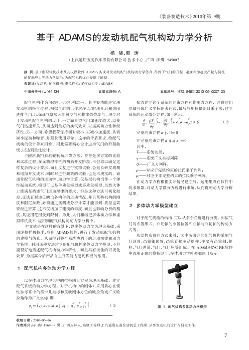
《装备制造技术》2010年第9期配气机构作为内燃机三大机构之一,其主要功能是实现发动机的换气过程,根据气缸的工作次序,定时地开启和关闭进排气门,以保证气缸吸入新鲜空气和排出燃烧废气。
现今对于发动机配气机构的设计,一方面希望气门加速度越大,以使气门迅速开关,从而达到最好的换气效果,以提高动力性和经济性;另一方面,希望载荷保持相对较小,以减小加速度,从而减小振动和噪音,并延长使用寿命。
这样的矛盾要求,给配气机构的设计带来困难,因此需要精心设计进排气门的升程曲线,以达到最优设计。
内燃机配气机构的传统开发方法,往往是多方案的比较和试凑过程,在无物理样机的初始开发阶段,不但难以满足这样复杂的设计要求,而且反复进行实物试验,会延长研发周期和增加开发成本,同时对进行频繁的试验,也是不现实的。
而通常配气机构的运动学、动力学计算,仅是把机构当作一个弹性振动系统,模型可以是单质量模型或多质量模型,虽然大体上能满足描述气门运动规律的要求,但是这种方法可视化较差,无法直观地反映出各构件的运动情况,并且某些机构的刚度和阻尼参数,必须通过实测或分析计算才能得到,质量也需要经过折算,这不仅增加了建模的难度,而且也影响分析的精度,其应用范围受到限制。
为此,人们相继把多体动力学和虚拟样机技术,应用到配气机构的动力学分析中。
本文就是在这样的背景下,以多体动力学为理论基础,采用虚拟样机技术,应用ADAMS软件,进行了发动机配气机构的建模与仿真,从而得到整个系统协调下的运动规律和动力学特性。
利用该种方法建立的配气机构多体动力学模型,不但能很好地描述配气机构动力学特性,而且具有极佳的可视化效果,为提高今后产品自主开发能力起到积极的作用。
1配气机构多体动力学方程以多体动力学理论中的拉格朗日方程为理论基础,建立配气系统的动力学方程。
对于机构中的刚体i ,采用质心在惯性参考系中的笛卡儿坐标和反映刚体方位的欧拉角或广义欧拉角作为广义坐标,即q i =[x ,y ,z ,准,θ,φ]Ti ,q =[q 1T,q 2T,q n T ]T(1)接着建立这个系统的约束方程和作用力方程,并将它们也都写成广义坐标的表达式,最后应用拉格朗日乘子法,建立系统的运动微分方程,如下所示。
最新ansys单词读音及英汉对照大全
1、ANSYS12.1 Workbench ['wɜrk.bentʃ]界面相关分析系统和组件说明【Analysis Systems】分析系统【Component Systems】组件系统【Custom Systems】自定义系统【Design Exploration】设计优化分析类型说明Electric (ANSYS) ANSYS电场分析Explicit Dynamics (ANSYS) ANSYS显式动力学分析Fluid Flow (CFX) CFX流体分析Fluid Flow (Fluent) FLUENT 精品文档流体分析Harmonic Response (ANSYS) ANSYS 谐响应分析Linear Buckling (ANSYS) ANSYS线性屈曲Magnetostatic (ANSYS) ANSYS静磁场分析Modal (ANSYS) ANSYS模态分析Random Vibration (ANSYS) ANSYS随机振动分析Response Spectrum (ANSYS) ANSYS响应谱分析Shape Optimization (ANSYS) ANSYS形精品文档状优化分析Static Structural (ANSYS) ANSYS结构静力分析Steady-State Thermal (ANSYS) ANSYS稳态热分析Thermal-Electric (ANSYS) ANSYS热电耦合分析Transient Structural(ANSYS) ANSYS结构瞬态分析Transient Structural(MBD) MBD 多体结构动力分析Transient Thermal(ANSYS) ANSYS瞬态热分析精品文档组件类型说明AUTODYN AUTODYN 非线性显式动力分析BladeGen 涡轮机械叶片设计工具CFX CFX高端流体分析工具Engineering Data 工程数据工具Explicit Dynamic(LS-DYNA)LS-DYNA 显式动力分析Finite Element Modeler FEM有限元模型工具FLUNET FLUNET 精品文档流体分析Geometry 几何建模工具Mechanical APDL 机械APDL 命令Mechanical Model 机械分析模型Mesh 网格划分工具Results 结果后处理工具TurboGrid 涡轮叶栅通道网格生成工具Vista TF 叶片二维精品文档性能评估工具2、主菜单【File】文件操作【View】窗口显示【Tools】提供工具【Units】单位制【Help】帮助信息3、基本工具条【New】新建文件【Open】打开文件【Save】保存文件【Save As】另存为文件【Import】导入模型【Compact Mode】紧凑视图模式精品文档【Shade Exterior and Edges】轮廓线显示【Wireframe】线框显示【Ruler】显示标尺【Legend】显示图例【Triad】显示坐标图示【Expand All】展开结构树【Collapse Environments】折叠结构树【Collapse Models】折叠结构树中的Models项【Named Selections】命名工具条【Unit Conversion】单位转换工具【Messages:Messages】信息窗口【Simulation Wizard】向导【Graphics Annotations】注释【Section Planes】截面信息窗口精品文档【Reset Layout】重新安排界面4、建模【Geometry】几何模型【New Geometry】新建几何模型【Details View】详细信息窗口【Graphics】图形窗口:显示当前模型状态【Extrude】拉伸【Revolve】旋转【Sweep】扫掠【Skin/Loft】蒙皮【Thin/Surface】抽壳【Thin】创建薄壁实体【Surface】创建简化壳【Face to Remove】删除面:所选面将从体中删除。
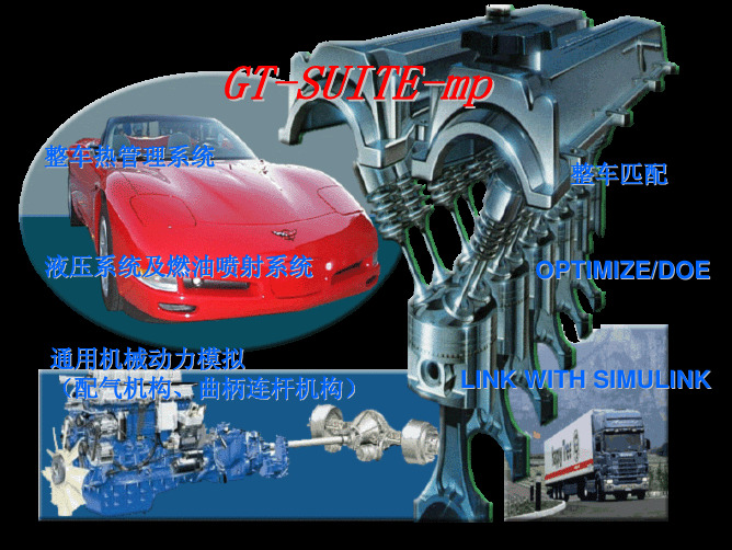
GT-SUITE-mp简介
机舱热管理
整车热回收
EGR Cooler Condenser (Engine Coolant)
Recuperator Receiver Pump
Expander
液压及燃油喷射系统模拟
z z z z z z
液压装置的配气机构 (可以选择与详细的发动机模型进行耦合) 喷射系统 行走液压系统 转向系统 制动系统 其它的液压系统
MBD
通用的MBD模型库
z z z z
1D / 1DR / 2D / 3D multi-body dynamics (MBD) 弹性部件 (2D/3D Rod, Beam, Superelement etc.) 刚度/阻尼,接触+磨擦, 和铰接单元 2D/3D接触中的运动和磨擦分析
2-D
Inertia2D Rod2D Beam2D Cable2D Solid2D
GT-SUITE - Just one!
原始CAD模型的导入
热态模拟
z
GT-SUITE 总是进行能量方程的求解
¾ ¾
完全的热求解, 从不进行 “等温”求解 求解快速, 没有理由进行等温求解
¾ ¾
当发现热的求解很重要时,不用进行模型的重新建立 不用付额外的费用 (客户将在最基本的价格的条件下获得最先进的模型)
•
Option: contact as a tangency constraint (no separation; useful in some analyses)
机械式VVA 系统 如: 摆式凸轮机构
算例: 摆动凸轮式的VVA装置
在MBD库中通过简化和超级单元来利用3D固体 FEA模型
Example: Valvetrain finger FE model 3-D Solid Model in ANSYS (60,000+ nodes)
多体动力学讲稿(car)version4

多体动力学(Adams/Car2007)摘要Adams/Car中多体系统的位置、姿态、运动及受力分析。
目录1 矢量 (3)1.1 矢量的定义和符号 (3)1.2 矢量的基本运算 (3)1.3 单位矢量的定义和符号 (4)1.4 零矢量的定义和符号 (4)1.5 平移规定 (4)2 坐标系 (6)2.1 坐标系的定义 (6)2.2 坐标系的分类 (6)2.3 I marker和J marker (6)3 矢量的坐标阵和坐标方阵 (7)4 方向余弦矩阵 (8)5 欧拉角 (11)6 描述车身姿态的3-2-1转角 (15)7 几个位置和姿态函数 (16)7.1 中心位置函数(LOC_CENTERED) (17)7.2 线上位置函数(LOC_ALONG_LINE) (18)7.3 轴上位置函数(LOC_ON_AXIS) (18)7.4 相对位置函数(LOC_RELATIVE_TO) (19)7.5 相对姿态函数(ORI_RELATIVE_TO) (20)7.6 平面姿态函数(ORI_IN_PLANE) (20)7.7 轴在线姿态函数(ORI_ALONG_AXIS) (21)7.8 轴定位姿态函数(ORI_ALIGN_AXIS) (22)8 力(Forces) (24)8.1 弹簧力(Springs) (24)8.2 阻尼力(Dampers) (25)8.3 轮胎力(Tires) (25)8.4 限位块(Bumpstops & Reboundstops) (25)8.5 橡胶衬套(Bushings) (27)9 约束(Joints) (30)9.1 滑移铰(Translational) (31)9.2 旋转铰(Revolute) (33)9.3 圆柱铰(Cylindrical) (35)9.4 球铰(Spherical) (36)9.5 平面铰(Planar) (38)9.6 固定铰(Fixed) (38)9.7 点在线约束(Inline) (39)9.8 点在面约束(Inplane) (39)9.9 姿态约束(Orientation) (40)9.10 平行约束(Parallel_axes) (40)9.11 垂直约束(Perpendicular) (40)9.12 虎克铰(Hooke) (42)9.13 万向节(Universal) (45)9.14 等速万向节(Convel) (47)9.15 关联约束(Coupler) (49)10 悬架试验台(MDI_SUSPENSION_TESTRIG) (50)11 悬架仿真试验多体系统(mdi_front_vehicle) (50)12 悬架仿真试验(Suspension Analysis) (51)12.1 平行轮跳试验(Parallel Wheel Travel Analysis) (51)12.2 反向轮跳试验(Opposite Wheel Travel Analysis) (52)12.3 单轮跳试验(Single Wheel Travel Analysis) (52)12.4 侧倾试验(Roll & Vertical Force Analysis) (53)12.5 转向试验(Steering Analysis) (53)12.6 静载试验(Static Load Analysis) (54)12.7 车轮轮廓试验(Wheel Envelope Analysis) (54)13 悬架仿真试验多体系统的静力学方程 (55)14 柔度矩阵(Compliance Matrix) (56)15 悬架仿真试验输出的特性参数(Output of Suspension Analysis) (58)参考文献 (62)附录一参数及变量定义表 (62)1 矢量我们所处理的物理量绝大部分是矢量,所以矢量的运算是本课程的基础内容。
能动专业英语词汇

能源与动力工程专业英语词汇专业名称•动力工程及工程热物理:Power Engineering and Engineering Thermophysics工程热物理:Thermal Physics of Engineering•动力工程:Power Engineering; Dynamic Engineering•热能工程:Thermal Engineering (Thermal Energy Engineering)•制冷与低温工程:Refrigeration and Cryogenic[ˌkraɪəˈdʒɛnɪk]Engineering •流体机械及工程:Fluid Mechanics and Engineering•热能动力工程:Thermal Energy and Dynamic Engineering•能源与动力工程学院:School of Energy and Power Engineering热力学thermodynamics1.adiabatic process[ˌædiəˈbætɪk]绝热过程2.aerodynamics[ˌeroʊdaɪˈnæmɪks]空气动力学,空气动力学专家,n,adj空气动力学的3.buoyancy[ˈbɔɪənsi,ˈbujən-]浮升力pressibility压缩性5.gasdynamics气体动力学6.hydraulics[haɪˈdrɔlɪks]水力学7.hydrodynamics流体水力学8.hydrostatics[ˌhaɪdrə'stætɪks]流体静力学9.open system开口系统10.reversible process[rɪˈvɚsəbəl]可逆过程11.thermod ynamics equilibrium[ˌikwəˈlɪbriəm]热力平衡12.viscous[ˈvɪskəs]粘性的13.inviscid[ɪn'vɪsɪd]无粘性的14.thermodynamics、thermodynamic property热力学、热力性质15.entropy[ˈɛntrəpi]熵16.enthalpy[en'θælpɪ]焓17.internal energy内能18.potential energy势能19.kinetic energy动能20.work功21.mechanical/shaft work机械功/轴功22.flow work流动功23.specific volume比容24.cycle循环25.Saturated temperature/pressure/liquid/ vapor[ˈsætʃəreɪtɪd]饱和温度/压力/液体/蒸汽26.subcooled liquid过冷液体27.quality(蒸汽)干度28.dry saturated vapor干饱和蒸汽29.superheated vapor过热蒸汽30.the first/second law of thermodynamics热力学第一/二定律31.the law of the conservation of energy能量守恒定律32.reversible/irreversible process可逆/不可逆过程33.pressure drop压降34.heat exchanger热交换器35.entropy production熵产[ˈɛntrəpi]36.coefficient of performance性能系数37.refrigerating capacity/effect制冷量38.Carnot cycle卡诺循环/nit/39.refrigerating efficiency制冷效率40.equation of state状态方程41.ideal gas constant理想气体常数42.isotherm等温线43.triple point三相点44.hydrocarbons碳氢化合物/烃45.cryogenic低温学[ˌkraɪəˈdʒenɪk]46.least-square fitting最小二乘法47.specific heat/specific heat capacity比热/比热容48.azeotropic mixture共沸混合物[əˌzi:ə'trɒpɪk]49.zeotropic mixture非共沸混合物50.dew point(temperature)露点(温度)[dju: pɔint][du pɔɪnt]51.isentropic compression/process等熵压缩/过程[aɪsen'trɒpɪk]52.condenser冷凝器53.evaporator蒸发器54.expansion valve膨胀阀55.throttling valve节流阀pressor压缩机pressor displacement压缩机排气量58.volumetric efficiency容积效率59.single-stage/two-stage/double-stage/compound compression单/双级压缩60.intercool/intercooler中间冷却(器)61.intermediate pressure中间压力62.pressure ratio压力比63.insulating material保温材料流体力学1.流体力学fluid mechanics2.动力粘度absolute/dynamic viscosity3.速度梯度velocity gradient英[ˈgreɪdiənt]美[ˈɡrediənt]4.运动粘度kinematic viscosity英[ˌkɪnɪ'mætɪk]美[ˌkɪnə'mætɪk]英[vɪ'skɒsətɪ]美[vɪˈskɑsɪti] 5.伯努力方程Bernoulli Equation英[bə:ˈnu:li iˈkweiʃən]6.体积流量volumetric flow rate7.质量流量mass flow rate8.层流laminar flow9.紊流turbulence/turbulent flow10.雷诺数Reynolds number11.摩擦力friction/frictional force12.摩擦系数coefficient of friction13.微分方程differential equation14.阻力drag force或resistance15.阻力系数drag coefficient传热学1.热传递heat transfer2.热传导thermal conduction3.热对流thermal convection4.热辐射thermal radiation5.层流底层laminar sublayer6.过渡层buffer layer,缓冲区或人,buffer dinner 自助餐buffet英[ˈbʌfit]7.强迫对流forced convection8.自然/自由对流natural/free convection9.稳态导热steady-state conduction10.导热系数thermal conductivity11.热阻thermal resistance12.(总)传热系数(overall)heat transfer coefficient13.表面积surface area14.串联series系列15.并联parallel英[ˈpærəlel]并行,Parallel computing并行计算16.接触热阻contact thermal resistance17.(对数)平均温差(logarithmic)mean temperature difference[ˌlɒɡə'rɪðmɪk]18.顺流parallel flow19.逆流counter flow20.相变phase change21.冷库cold storage热库thermal reservoir/heat bath22.边界条件boundary condition23.黑体辐射blackbody radiation24.辐射力emissive power25.维恩位移定律Wien’s displacement Law26.半球发射率hemispherical emittance[ˌhemɪˈsferɪkl]27.吸收率absorptance英[əb'sɔ:ptəns]28.透射率transmittance英[træns'mɪtns]n.播送;发射;传动;透明度;29.反射率reflectance30.漫射辐射diffuse radiation31.(充分发展的)层流/紊流fully developed laminar/turbulent flow湿空气1.湿空气学psychrometrics2.干空气dry air3.湿空气moistair4.大气压barometricpressure5.热力学温标thermodynamic temperature scale6.含湿量humidity ratio7.比焓specific enthalpy英[en'θælpɪ]8.比熵specific entropy英[ˈentrəpi]9.绝对湿度absolute humidity10.饱和含湿量saturation humidity ratio英[ˌsætʃəˈreɪʃn]英[ˈreɪʃiəʊ]11.相对湿度relative humidity12.热力学湿球温度thermodynamic wet-bulb temperature13.分压力partial pressure14.总压total pressure15.通用气体常数universal gas constant16.湿球/干球温度dry-bulb/wet-bulb temperature17.焓湿图psychrometric chart制冷空调1.集中/分散供冷central/decentralized cooling英[ˌdi:'sentrəlaɪzd]2.锅炉boiler3.往复/螺杆/离心/涡旋式压缩机/冷水机组reciprocating/helical rotary(或screw)/centrifugal/scroll compressor/water chiller unit4.吸收式制冷/冷水机组absorption refrigeration/water chiller unit5.热回收heat reclaim/recovery6.冷却塔cooling tower7.空气/水冷却冷凝器air-cooled/water-cooled condenser8.蒸发式冷凝器evaporative condenser9.净正吸入压力/压头netpositive suction pressure/head10.供/回干管main supply/return line11.二/三通阀two/three-way valve12.平衡阀balancing valve13.一次/二次冷冻水系统primary/secondary chilled water system14.备用泵spare pump15.疏水器、存水弯、水封trap16.水/冰蓄冷water/ice thermal storage17.空气/水/地源热泵air/water/ground source heat pump18.定/变风量constant/variable air volume19.经济器economizer20.静/动压static/dynamic pressure21.毛细管capillary tube英[kəˈpɪləri]22.全封闭压缩机hermetically sealed/hermetic compressor英[hɜ:ˈmetɪk]23.半封闭式压缩机semi-hermetic/semi-hermetically sealed compressor24.直接膨胀direct expansion26.离心/轴流式风机centrifugal/axial fan英[ˈæksiəl]27.立管riser英['raɪzə]28.内/外平衡式热力膨胀阀internally/externally equalized thermostatic expansion valve29.吸/排气管suction/discharge line30.电磁阀solenoid valve美['solə,nɔɪd]31.恒压阀constant pressure valve32.迎风面积/速度face area/velocity33.(一拖多)分体式空调器(multi-)split air conditioner34.水环热泵water loop heat pump35.能效比energy efficiency ratio36.变容压缩/压缩机positive displacement compression/compressor37.速度/动压式压缩/压缩机velocity/dynamic compression/compressor38.流量系数flow coefficient39.水锤water hammer40.闸阀gate valve41.球阀ball valve42.蝶阀butterfly valve43.平衡阀balancing valve44.安全阀safety/relief valve n.救济;减轻,解除;安慰;浮雕45.止回阀check/backflow prevention valve boiler锅炉1.air heater空气预热器2.auxiliary辅助的,辅机[ɔ:gˈzɪliəri]3.bare tube光管4.blast[英][blɑ:st]鼓风5.blowdown排污6.capacity[英][kəˈpæsəti]出力7.cogenerator热电联产机组pressor压缩机bustion燃烧10.condenser凝汽器11.counterflow逆流12.critical pressure临界压力13.diesel oil柴油gasoline,gaslene, gas,petro(英),汽油14.drainage疏水、排水设备,排水系统15.drum汽包16.economizer[英][i:'kɒnəmaɪzə]省煤器17.excess air[英][ɪkˈses]过量空气18.extended surface扩展受热面19.fin鳍片、肋片、散热片、翅片20.flue gas烟气21.fluid(-)bed流化床(fluidizedbed)[英]['flu:ɪdaɪzd22.furnace炉膛23.fouling污垢,击球出界(羽毛球)[英]['faʊlɪŋ]24.generator发电机25.header联箱、集箱,集管26.hopper[英][ˈhɒpə(r)]斗、料斗l磨煤机(pulverizer)[英]['pʌlvəraɪzə]28.motor汽车、马达、电动机29.platen屏、管屏[美]['plætən]30.Prandtl numbers普朗特数31.pressure loss压力损失32.regenerator回热器,蓄热器,再生器[英][rɪ'dʒenəˌreɪtə]33.Reynolds numbers雷诺数34.slag结渣美[slæɡ]35.sootblower吹灰器美[su:tb'ləʊər]36.steam line blowing蒸汽管路吹洗37.superheater过热器38.turbine汽轮机39.suction真空,负压steam turbine蒸汽轮机40.gas turbine燃气轮机41.back pressure背压42.blower送风机、吹灰器43.boundary layer边界层44.chimney英[ˈtʃɪmni]烟囱、烟道、烟筒45.cooling tower冷却水塔46.coupling连接,连接法兰,耦合47.critical speed临界转速48.cylinder圆筒、汽缸49.head汽包封头、扬程、水头50.impeller叶轮、推进器、压缩器rge turbine-generator unit大型汽轮发电机组52.non-destructive testing(NDT)无损检验53.digital-controlled machine数控机床54.fixed blade固定叶片,导向叶片55.operational speed运行转速56.outing casing外缸57.inner casing内缸58.rigid coupling刚性连轴器solid coupling59.rotor转子60.stress concentration应力集中61.two-shift operation两班制运行62.wake尾流Thermal Power Plant:热电厂1.automatic control system:自动控制系统2.boiler feed pump:锅炉给水泵feed pump:给水泵3.chamber:燃烧室/ei/4.circulating water:循环水5.check valve:止回阀,逆止阀6.non-return valve:逆止阀,止回阀7.controlling valve:控制阀,调节阀8.cooling water(CW):冷却水9.cycle efficiency:循环效率10.data processing system:数据处理系统11.de-aerator[英]['eɪəreɪtə]除氧器12.de-aerator tank:除氧水箱13.desuperheater:减温器14.desuperheater spraywater:喷水减温15.drain pump:疏水泵16.full-load:满负荷erning system:调速系统(governing:调节,调整)18.heat-transfer coefficient:换热系数19.isolating valve:隔离阀20.load rejection:甩(抛)负荷21.main steam:主汽22.motorized isolating valve:电动隔离阀23.lubricating oil:润滑油24.nuclear plant:核电厂25.orifice:[orifis]孔,口,孔板26.pipework:管路27.power station:电厂28.pressure reducing valve:减压装置29.reliability:安全性,可靠性30.relief valve:安全阀31.running speed:运行转速32.sealing:密封,封闭,焊封33.self-sealing:自密封的34.stainless steel:不锈钢35.stop valve:断流阀,截止阀36.strainer:滤盆,滤器,滤网,拉紧装置37.supercritical plant:超临界机组38.synchronizer:英]['sɪŋkrənaɪzə]同步器,同步机,同步装置39.throttle:节流阀[美]/ˈθrɑ:tl/喉咙,气管,vt.&vi.扼杀,压制;勒死,使窒息;使节流40.turbine-generator unit:汽轮发电机组41.ultra-supercritical:超超临界英][ˈʌltrə] [美]['ʌltrə]42.vacuum:真空43.vent:通道,通风口44.actuator:/aiktjueite/执行机构45.brake:闸,制动器46.damper:[美]['dæmpər]挡板,调节风门47.distributed control system(DCS)分散控制系统48.disturbance:干扰,扰动49.feedback control:反馈控制50.forced draught(FD)fan:送风机[英][fɔ:st drɑ:ft/51.furnace purge:炉膛吹扫ernor valve:调节阀53.induced draught(ID)fan:引风机54.make-up pump:补水泵55.overheating:过热,超温56.preamp:前置放大器/ˈpriæm p/57.primary air fan:一次风机58.sensor:传感器59.shutdown:停机,停炉,停运,关机,关闭;倒闭,停工,停业,停播。
多体系统动力学基本理论

i1 j1 k1
cos sin 0 A1 sin cos 0 0 0 1
i
i1 (i2 ) i3
j
i1 j1 k1
i1 i2 j j 1 A2 2 , k1 k 2
Name DADS ADAMS Formulation method Newton Euler First Lagrange Results Time history Animation Time history Animation Frequency Response Time history
NEWEUL
Newton Euler
MEDYNA
CADAMB
Newton Euler
Jourdain Principle
Time history
Time history
虚拟样机建模
运动学和动力学建模过程 (1) 输入运动学和动力学分析有关参数 (2) 运动学方程和动力学方程求解 (3) 数据输出和动画显示
2.1 机械系统的多体动力学模型
B0
拓扑结构
闭环多体系统
J2
B1 J1
B2
B3 J3 J4
B0
曲柄连杆机构
B1 B2
J1, J2, J3 为旋转铰, J4 为滑移铰
B3
B0
拓扑结构
拓扑结构构成回路
运动学分析过程
(q ) 0 qq t , q q (qq)q q 2qt q tt
i sin sin cos 3 sin cos sin j3 (cos ) k3
- 1、下载文档前请自行甄别文档内容的完整性,平台不提供额外的编辑、内容补充、找答案等附加服务。
- 2、"仅部分预览"的文档,不可在线预览部分如存在完整性等问题,可反馈申请退款(可完整预览的文档不适用该条件!)。
- 3、如文档侵犯您的权益,请联系客服反馈,我们会尽快为您处理(人工客服工作时间:9:00-18:30)。
Article ID:100420579(2000)0420375205Multibody System Dynamics Analysis for V alve T rainsQ IN Wen2jie, ZUO Zheng2xing(School of Vehicle and Trans portation Engineering,Beijing Institute of Technology,Beijing100081)Abstract:The theory of multibody system dynamics is used to simulate valve trains’kinematicsand dynamics characteristics,and the methods of establishing and analyzing the multibody sys2tem dynamics model for valve trains are discussed.Since most of the flexible bodies of a valvetrain are slender parts,the finite segment method is used to build their models.Other parts suchas cams,valve heads etc.,are built as rigid bodies.After applying the constraints,forces andmotions,the establishing of the whole system is accomplished,and the Lagrange’s multipliermethod can be used to obtain its dynamics constitutive equations.As an example,a valve trainπsmultibody system model of4100QB engine made by the Yunnan Internal Combustion EngineLimited2Liability Company is established,and the analysis results obtained show that its work2ing performance is generally good except that the air2pass ability and the lubrication effect of thecam and the tappet have to be improved.K ey w ords:valve train;multibody system;dynamicsC LC number:T K4 Document code:AValve trains are broadly used to control the induction and exhaust of four2stroke engines. They are usually designed as rigid systems,in which valves’movements are completely controlled by the cam’s profiles.In fact,a valve train is an elastic system and the valve’s motion will devi2 ate from the theoretical result derived from the kinematics analysis due to the effect of the inertia and the elastic vibration.Thus the separation in the mechanism will occur and this will make its working conditions worse[1].With the improvement of engine’s speed,these dynamics problems become more and more significant.Therefore,the valve train’s dynamics characteristics must be checked.Usually a valve train is considered as a single2mass or multi2mass vibration system in the dy2 namic analysis[2].But this method cannot reflect the parts’movement and deformation directly, and the model’s parameters must be derived from experiments or other analysis.This will in2 crease the difficulties of model establishment and influence the calculation’s explicitness.Multi2 body system dynamics is a new science which studies the mechanics properties of the system com2 posed of flexible bodies and rigid bodies during the large span spatial movements.According to such a structure2mechanism system as a valve train,using it can not only simulate the motions andR eceived d ate:2000206212Biography:QIN Wen2jie(1968-),female,lecturer,master.dynamics properties of the system,but also calculate the loads of each part,which can be provid2 ed for part’s structure analysis and design.1 V alve T rain’s Multibody System Model EstablishmentThe process of model establishment can be divided into two stages.The first is to build the single valve train’s model for the calculation of valve’s motion and optimization of cam’s profile. The second is to build the whole valve train’s model for the torsion dynamics analysis of the camshaft.However,the establishment of single valve train’s model is the basis for all these anal2 yses,and its method is discussed as follows.111 Establishing Parts’ModelsIf a part’s deformation is not taken into account,it is called a rigid body.If the deformation of a part must be calculated,it is called a flexible body.If just a part’s translation must be calcu2 lated and its rotation is ignored,it can be simplified as a point mass.It is relatively simple to es2 tablish the model of a rigid body or a point mass,so only the method of establishing the flexible body model is discussed here.During the establishment of a flexible body’s model,the finite element method is usually used as preprocessing to obtain mode shapes.By using the relative description method,a part’s motion can be divided into the global reference frame’s large displacement and rotation and its de2 formation motion which is definite with respect to the moving reference frame and can be approxi2 mated with a linear combination of mode shapes[3].Most of the flexible parts of a valve train are slender parts such as rods(tappets,radius rods and valve stems)and beams(camshafts and rocker shafts),so the finite segment method is a sim2 ple and effective way to establish models of this kind of part.The thought of this method is to di2 vide a rod or beam into several rigid segments which are linked with flexible connectors.For a uniform cross2section rod,since only the axial stiffness is concerned,a spring2damper can be added to the two ends of each segment and its stiffness value is[4]k=2A E/L,(1) where A is the uniform area of the rod’s cross section;E is the Y oung’s modulus of elasticity for the material;L is the length of the rod segment.For a uniform beam,the constitutive equation of the flexible connector on each end of the segment is[5]Q=-Kδ-Cδ・,(2) where Q,δ,δ・are the force,displacement and velocity vectors respectively in the local coordinate system;K and C are the stiffness and damper matrix.Both of them are symmetric.According to the theory of Timoshenko Beams,concerning the effect of cross2section rotation and shearing,K can be defined as[5]K =EA /L 00000012EI zL 3(1+P y )000-6EI z L 2(1+P y )0012EI yL 3(1+P z )06EI y L 2(1+P z )0000GI x L 00006EI yL 2(1+P z )0(4+P z )EI y L (1+P z )00-6EI zL 2(1+P y )000(4+P y )EI zL (1+P y ),where A is the uniform area of the beam ’s cross section ;L is the length of the beam segment ;P y =12EIz A y /(GA L 2);P z =12EI y A z /(GAL 2);G is the shear modulus.A y is the shear arearatio for shear deflection in the y direction.A zis the shear area ratio for shear deflection in the z direction.112 Applying Constraints ,Forces and MotionsThere are revolute joints ,translational joints ,fixed joints ,point 2to 2curve contacts and curve 2to 2curve contacts in a valve train.The revolute joints and translational joints can either be simply idealized joints or be joints with friction.The main forces in a valve train are the valve s pring force and gas pressure applied to the valve head.The gas pressure is usually ignored because its small effect on the mechanism.The valve spring can be defined as the linear spring 2damper ,non 2linear spring 2damper or multi 2mass spring.The motion is just the rotation of the camshaft.2 Constitutive Equations of Multibody System DynamicsUsing the Lagrange ’s equation ,the dynamics equation of each part can be described in the form of the blocking matrix as [3]M rrM r θM rf M rθM θθM θf M rf M θf R ff ¨r θ・q f +00000000K ff r θq f =Q r Q θQ f +Q vr Q v θQ vf ,(3)where M is the part ’s mass matrix ;r and ¨r are the location vector and acceleration of the moving reference frame respectively ;θis the Euler angles which describe the orientation of the moving reference frame ;and θ・is its derivative with respect to the time ;q f is the generalized coordinates to describe the deformation of the moving reference frame ;Q is the generalized force vector with respect to the active forces ;Q v is the generalized force vector relative to the second power of the velocity.The subscripts r ,θand f represent the translation ,rotation and deformation res pective 2ly.Apparently ,if a part ’s deformation is not taken into account ,i.e.q f =0, q f =0,¨q f =0,the dynamics equations for rigid bodies are obtained.QIN Wen 2jie et al./M ultibody System Dynamics A nalysis f or V alve T rainsAssembling the parts together by applying the constraint functions and using the Lagrange πs multiplier method ,the system πs dynamics constitutive equations and constraint functions are ob 2tained as [3]M ¨q +Kq +C T q λ=Q F +Q v , C (q ,t )=0.(4)In Eq.(4),the mass matrix M =diag [M 1,M 2,…,M n ];the stiffness matrix K =diag[K 1,K 2,…,K n ];the constraint ’s Jacobian matrix C T q =[C T 1,C T 2,…,C T m ]T ;the generalizedforces Q F =[Q F1,Q F2,…,Q F n ]T ,Q v =[Q v1,Q v2,…,Q v n ]T ;the generalized coordinate vectors q =[q T 1,q T 2,…,q T n ]T ;the Lagrange ’s multipliers λ=[λ1,λ2,…,λm ]Tin which n is the num 2ber of parts ,m is the number of constraints and t is the time.3 ExampleIn order to verify the design of the valve train of 4100QB engine made by Yunnan Internal Combustion Engine Limited 2Liability Company ,the single valve train ’s multibody system model is established using the mechanical system simulation software ADAMS as Fig.1,and the follow 2ing are some of theresults.Fig.1 The valve train ’s multibody system modelThe valve ’s displacement ,velocity and acceleration results under the camshaft ’s lowand Fig.2 The valve ’s displacement ,velocity and acceleration curveshigh rotation speed are shown in Fig.2.The contact forces and stresses of the cam 2tappet and the rocker 2valve under the engine ’s rated rotational speed are shown as Fig.3and Fig.4.Journal of Beijing Institute of Technology ,2000,Vol.9,No .4Fig.3 The cam 2tappet contact force and stress curves Fig.4 The rocker 2valve contact force and stress curvesThe figures show that there is no separation occurring in the mechanism ,and the velocity with which the valve drops to the seat and the contact stresses are less than the permissible val 2ues.These results indicate that the working performance of this valve train is generally good.From the valve ’s motion results ,the ample factor of the valve lift and the lubrication charac 2teristics coefficient of the cam and tappet can be calculated.The ample factor is equal to 01502and the derivative of the lubrication characteristics coefficient with res pect to the cam rotation an 2gle at the zero point is less than 3mm/(°).These results show that the air 2pass ability and the lu 2brication effect are not very good ,so it is essential to optimize the cam ’s profile.R eferences :[1] Xu Wu.Modern design of vehicle engines (in Chinese )[M ].Beijing :People ’s CommunicationsPublishing House ,1995.[2] Li Huizhen ,Yuan Zhaochen ,Le Yunbing ,et al.Development of valve cam design[J ].ChineseInternal Combustion Engine Engineering (in Chinese ),1989,10(1):32-37.[3] Lu Y oufang.Dynamics of flexible multibody systems (in Chinese )[M ].Beijing :Higher Educa 2tion Publishing House ,1996.[4] Huston R L ,Liu Y ouwu.Dynamics of multibody system (in Chinese )[M ].Tianjing :TianjingUniversity Press ,1987.[5] Oden J T ,Ripperger E A.Mechanics of elastic structure[M ].New Y ork :Mc Graw 2Hill ,1981.配气机构的多体系统动力学分析覃文洁, 左正兴(北京理工大学车辆与交通工程学院,北京 100081)摘 要:运用多体系统动力学的原理来模拟配气机构的运动学和动力学特性,讨论了配气机构多体系统动力学建模和分析的方法.由于配气机构中的柔体多是细长零件,可采用有限段的方法建立其模型,其它零件如凸轮、气门头等视为刚体,再施加上约束、力和运动激励之后即完成了整个系统模型的建立.其动力学方程可采用拉格朗日乘子法建立.作为一个应用实例,对云南内燃机股份有限公司生产的4100QB 发动机的配气机构进行了建模分析,结果表明该机构的运行情况良好,但气门的通过能力以及凸轮2挺柱副的润滑效果有待进一步提高.关键词:配气机构;多体系统;动力学QIN Wen 2jie et al./M ultibody System Dynamics A nalysis f or V alve T rains。