
LED_KEY_Driver
LED设备驱动
static int __init dev_init(void) { int ret; int i; for (i = 0; i < 4; i++) { s3c2410_gpio_cfgpin(led_table[i], led_cfg_ table[i]); s3c2410_gpio_setpin(led_table[i], 0); } ret = misc_register(&misc); printk (DEVICE_NAME"\tinitialized\n"); return ret;
LED设备驱动
static int sbc2440_leds_ioctl( struct inode *inode, struct file *file, unsigned int cmd, unsigned long arg) { switch(cmd) { case 0: case 1: if (arg > 4) { return -EINVAL; } s3c2410_gpio_setpin(led_table[arg], !cmd); return 0; default: return -EINVAL; } }
KEY 设备驱动
int main(void) { int buttons_fd; char buttons[6] = {'0', '0', '0', '0', '0', '0'}; /*定义按键值变量*/ buttons_fd = open("/dev/buttons", 0); /*打开按键设备/dev/buttons*/ if (buttons_fd < 0) { perror("open device buttons"); /*打开失败则退出*/ exit(1); } /*永读按键并打印键值和状态*/
嵌入式系统原理与开发
LED与设备驱动
LED设备驱动
#include <linux/miscdevice.h> #include <linux/delay.h> #include <asm/irq.h> #include <mach/regs-gpio.h> #include <mach/hardware.h> #include <linux/kernel.h> #include <linux/module.h> #include <linux/init.h> #include <linux/mm.h> #include <linux/fs.h> #include <linux/types.h> #include <linux/delay.h> #include <linux/moduleparam.h> #include <linux/slab.h> #include <linux/errno.h> #include <linux/ioctl.h> #include <linux/cdev.h> #include <linux/string.h> #include <linux/list.h> #include <linux/pci.h> #include <linux/gpio.h> #include <asm/uaccess.h>
KEY 设备驱动
for (;;) { char current_buttons[6]; int count_of_changed_key; int i; /*使用 read 函数读取一组按键值(6个)*/ if (read(buttons_fd, current_buttons, sizeof current_buttons)!=sizeof current_buttons) { perror("read buttons:"); exit(1); } /*逐个分析读取到的按键值*/
KEY 设备驱动
if (count_of_changed_key) { printf("\n"); } } /*关闭按键设备文件*/ close(buttons_fd); return 0; }
测试程序
#include <stdio.h> #include <stdlib.h> #define LED_ON 1 #define LED_OFF 0 #define LED_DEVICE "/dev/leds"
测试程序
int main(int argc,char **argv) { int fd,led_num; fd = open(LED_DEVICE,0); if(fd < 0) { printf("can't open /dev/leds!\n"); exit(0); } led_num = atoi(argv[1]); if(!(strcmp(argv[2],"on"))) { ioctl(fd,LED_ON,led_num); }
KEY 设备驱动
for (i = 0, count_of_changed_key = 0; i < sizeof buttons / sizeof buttons[0]; i++) { if (buttons[i] != current_buttons[i]) { buttons[i] = current_buttons[i]; /*打印按键值,并标明按键按下/抬起的状态*/ printf("%skey %d is %s", count_of_changed_key? ", ": "", i+1, buttons[i] =='0' ? "up" : "down"); count_of_changed_key++; }
4.3.1 设备驱动概述
static void __exit dev_exit(void) { misc_deregister(&misc); } module_init(dev_init); module_exit(dev_exit); MODULE_LICENSE("GPL"); MODULE_AUTHOR("FriendlyARM Inc.");
LED设备驱动
static struct file_operations dev_fops = { .owner = THIS_MODULE, .ioctl = sbc2440_leds_ioctl,
};
static struct miscdevice misc = { .minor = MISC_DYNAMIC_MINOR, .name = DEVICE_AME, .fops = &dev_fops, };
测试程序
} }
else if(!(strcmp(argv[2],"off"))) { ioctl(fd,LED_OFF,led_num); } else { exit(0); } exit(0);
嵌入式系统原理与开发
KEY设备驱动
KEY 设备驱动
#include <stdio.h> #include <stdlib.h> #include <unistd.h> #include <sys/ioctl.h> #include <sys/types.h> #include <sys/stat.h> #include <fcntl.h> #include <sys/select.h> #include <sys/time.h> #include <errno.h>
LED设备驱动
LED设备驱动
LED设备驱动
static unsigned long led_table [] = { S3C2410_GPB(5), S3C2410_GPB(6), S3C2410_GPB(7), S3C2410_GPB(8), }; static unsigned int led_cfg_table [] = { S3C2410_GPIO_OUTPUT, S3C2410_GPIO_OUTPUT, S3C2410_GPIO_OUTPUT, S3C2410_GPIO_OUTPUT, };
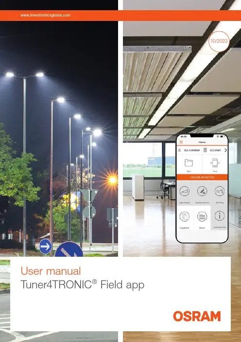
Tuner4TRONIC现场应用程序用户手册说明书
10/2023User manualTuner4TRONIC® Field appContents1 Introduction 032 System requirements 04 2.1 Smartphone 04 2.2 NFC scanner 04 2.3 Important programming information 04 2.4 Supported Tuner4TRONIC® files 04 2.5 LED driver password protection 04 2.6 Supported LED drivers 043 Quick start 05 3.1 App download 05 3.2 Quick overview 054 Features in detail 06 4.1 General 06 4.2 Light output 06 4.3 Dimming (outdoor drivers only) 06 4.4 Constant lumen 07 4.5 Additional luminaire info 07 4.6 Copy/paste configuration 08 4.7 P rogramming of configuration files provided by 09the luminaire manufacturer4.8 Service key password management 10 4.9 NFC scanner 11 4.10 Report 12 4.10.1 Driver settings 12 4.10.2 Monitoring data 13 4.11 Slider (hamburger menu) 13 4.11.1 Service keys 13 4.11.2 Support/send feedback 13 4.11.3 Share app 13 4.11.4 Change language 13 4.11.5 Online services 13 4.11.6 About 135 Compatible products 14Please note:All information in this guide has been prepared with great care. Inventronics, however, does not accept liability for possible errors, changes and/or omissions. Please check or contact your sales partner for an updated copy of this guide. This user guide is for information purposes only and aims to support you in tackling the challenges and taking full advantage of all opportunities the technology has to offer. Individual appli-cations may not be covered and need different handling. Responsibility and testing obligations remain with the luminaire manufacturer/OEM/application planner. Google Play and the Google Play logo are trademarksof Google Inc. Android is a trademark of Google Inc.iPhone is a trademark of Apple Inc. App Store is a service mark of Apple Inc.WarningIncorrect or unauthorized adjustments of a luminaire’s cru-cial parameters might lead to damage or unsafe operation of the luminaire or have an impact on the luminaire certifi-cation! The Tuner4TRONIC® Field app cannot verify the correctness of your configuration for the intended luminaire. You have to be aware of the risk that certain configurations might not be suitable for certain luminaires connected to the OSRAM LED driver and might lead to a permanent dam-age or change in performance of the overall system. Conse-quently, before adapting the configuration of OSRAM LED drivers in any way, always read the driver’s technical docu-mentation and application guide as well as the technical documentation of the luminaire or lighting fixture intended to be used with the OSRAM LED driver. In any case, do not use the Tuner4TRONIC® Field app to adapt the configuration of a system comprising an OSRAM LED driver unless you have ensured you are completely aware of the consequences of such an adaptation.1Luminaire manufacturerprograms LED drivers specifically2Luminaires are kept in stock for installation and replacement3Installer adjusts the light output ofLED drivers before initial installation4Luminaire fails5Installer reads the original configuration from the failed luminaire and pastes the data into the new luminaire1 IntroductionThe installation and maintenance of indoor and outdoor lu-minaires with our NFC technology is as easy as it gets – thanks to the Tuner4TRONIC ® Field app, which works on NFC-ready Android smartphones and iPhones. In combi-nation with the corresponding standard lumi n aires and compatible OSRAM NFC LED drivers, the Tuner4TRONIC ® Field app can be used for programming via NFC.NFC, which is short for Near-Field Communication, allows the programming of the drivers in the field – wirelessly and without mains voltage. In most cases, it is possible to read-out the driver’s configuration even after the device’s failure.With the Tuner4TRONIC ® Field app, certain luminaire set-tings can be easily adjusted according to the specific needs and within a predefined range set by the luminairemanufacturer. For indoor and outdoor applications, a typical example is the adjustment of the light output depending on the required application. Using outdoor drivers, the dimming levels can be changed in order to optimize energy savings and you can also disable the dimming functionality for spe-cial applications such as roundabouts or pedestrian cross-ings.With the Tuner4TRONIC ® Field app, replacing a luminaire becomes more efficient than ever before. Using the copy-and-paste function of the app, the settings of the original luminaire (indoor and outdoor) can be easily transferred tothe new one in a matter of seconds. There is no need to check how the old luminaire was configured, the whole process is completely offline and you are not forced to store your data in a cloud.Tuner4TRONIC ® Field app | System requirements2 System requirements2.1 SmartphoneThe minimum system requirements for the Tuner4TRONIC ® Field app are:—Android smartphone with integrated NFC antenna (Android OS 6.0)—Apple (iOS 9) with NFC scannerPlease note that the quality of NFC antennas built into Android smartphones can vary from phone to phone. Some antennas perform perfectly and some are comple - tely unusa b le. We have tested the NFC antennas of thef ollowing devices and recommend them for use with the Tuner4TRONIC ® Field app: —CAT S60 —HTC One M8—Samsung S7 and S82.2 NFC scannerIn case your smartphone has a low-quality NFC antenna, does not have an NFC antenna at all or does not allow the full use of the internal NFC antenna, such as the iPhone, you can use an optional NFC scanner. This device can be easily connected to the smartphone via Bluetooth using the Tuner4TRONIC ® Field app and provides a reliable and sta-ble NFC connection. It also offers a more comfortable way of programming LED drivers assembled in a luminaire. See chapter 4.7 for more information.2.3 Important programming informationWhen programming an LED driver, make sure that the NFC antenna of your smartphone (or of the NFC scanner)is aligned with the NFC antenna of the LED driver () after (not before!) pressing the programming button in the Tuner4TRONIC ® Field app to ensure successful data trans-fer. Do not move the LED driver during the programming to avoid errors in the NFC data transfer. If the programming fails and the driver is no longer responsive, please power on the driver to reset it. For safety reasons, please make sure to program LED drivers only when they are not pow-ered by mains. The position of the NFC antenna in the driv-er varies between products. As a general rule, t he smart-phone needs to be touching the NFC logo on the LEDdriver ().2.4 Supported Tuner4TRONIC ® filesThe Tuner4TRONIC ® Field app can only load configuration files with the file ending .osrtup.2.5 LED driver password protectionFor safety reasons, the luminaire manufacturer can protect the safety-relevant settings of the LED driver with a master key and allow the modification of non-critical settings such as dimming and light output within predefined limits. This is to ensure that no unauthorized person is able to modify the settings in a way that could cause safety problems. If an LED driver has a master key set and the Tuner4TRONIC ® Field app is not able to modify the LED driver’s settings, please contact the luminaire manufacturer.For additional protection, the luminaire manufacturer can set a service key on the LED driver. In case your LED driv-ers are protected with a service key, please contact the lu-minaire manufacturer to get the corresponding service key to be able to program the protected drivers.2.6 Supported LED driversA link to a list of all compatible LED drivers is provided inchapter 6.Tuner4TRONIC ® Field app | Quick start3 Quick start3.1 App downloadThe Tuner4TRONIC ® Field app can be downloaded from /tuner4tronic#software_downloadsSide menu incl. technical support featuresNotification area shows active NFC antenna and toggles between the internal NFC antenna and the NFC scanner via BluetoothLoad configuration fileAfter reading a configura-tion, the light output can be adjusted here in lumens, % or mACopy the last workingconfiguration of a defective LED driver and paste it into a new oneRead an LED driverAdjust the AstroDIM levels and times or switch to “no dimming” (ON/OFF)Edit constant light output tableRead data from driversEdit luminaire info3.2 Quick overviewHere is a quick overview to get you started with the app:Set ValueCancelOk106541091094 Features in detail4.2 Light outputYou can modify the light output of the LED drivers inl umens, percentage or milliamps. If the luminaire manu-facturer enables the "Tuning Factor", the light output can only be set within the min. and max. limits of the tuning factor settings.4.3 Dimming (outdoor drivers only)At the top of the dimming screen, you can choose between AstroDIM (time-based, astro-based) and “no dimming” (ON/OFF). At the bottom, you will find the dimming levelsand dimming times as well as the programming button.4.1 GeneralIn order to edit light output, CLO, DIM or additional lumi-naire info, you need to read data from the LED driver first by pressing the "Read" tile. All data will be downloaded, edited and finally uploaded to the driver when pressing the "Program" button. Due to this, only the driver that has been identified by its serial number when reading can be pro-grammed. To program a second driver, data from this sec-ond driver needs to be read accordingly.Tapping on the light output value in the middle of the circle enables you to enter an exact value.4.5 Additional luminaire infoThis feature allows editing the field “additional luminaire in-fo” (DALI MemBank 1) by either entering text, a string from QR code or GPS data from an actual location. If the string represents a valild URL (preceeding blanks and characters after blank mid of string ignored), pressing the info button next to the picture of the LED driver will open the URL in the browser.4.4 Constant lumenYou can enable/disable and edit constant lumen of LED drivers by entering value pairs for operating time [kh] andoutput level [%].24:002:004:00astro-based time-basedTime-based: The dimming levels and times refer to the switch-on time of the LED driver.Astro-based: The dimming levels and times refer to the middle of the night, which is calculated based on the sun-rise and sunset times.4.6 Copy/paste configurationThe Tuner4TRONIC® Field app features a copy/paste func-tion to simplify the replacement of the LED driver in a lumi-naire.Simply tap the “Read” button and scan the old LED driver with your smartphone, get the new LED driver and press the “Write” button to paste the configuration into the new LED driver.All of the driver’s parameters and settings are copied during the process, including the DALI short address. The only parameters that are not copied are the unique serialn umber and the monitoring data of the LED driver.To allow copying of data to next-generation LED drivers, the T4T-Field app will access the product family programming service from the cloud (if the smartphone is connected to the Internet).1Luminaire fails2Installer copies the original configurationfrom the old luminaire3Installer pastes the configurationinto the new luminaire4.7 Programming of configuration files provided by the luminaire manufacturerIt is possible to load Tuner4TRONIC® configuration files (*.osrtup) directly from your e-mail. Inside your e-mail app, download and open the configuration file received. The Tuner4TRONIC® Field app will open and confirm that the file was saved into the memory. If it does not open auto-matically, select the Tuner4TRONIC® Field app as the desti-nation app to open the file. Inside the Tuner4TRONIC® Field app, you can then go to the “Open file” screen, select a configuration file from the list and write that configuration into your LED driver.If the smartphone is connected to the Internet, data from the production file can be used to program next-generation LED drivers as well (product family programming service).1Luminaire manufacturersends an e-mail with the configuration file (*.osrtup)2Installer loads the file andprograms the driverE-mail4.8 Service key password managementIf the luminaire manufacturer has protected the driver with a service key to avoid unauthorized modifications, youhave to enter the service key in the Tuner4TRONIC ®Field app: Only users that have received the service key from the luminaire manufacturer can modify the driver config-uration. To make the handling of service keys easier, a user can save many service keys in the Tuner4TRONIC ® Field app and give them a name. During programming, the Tuner4TRONIC ® Field app uses the selected service key and authenticates it automatically. Provided the key is correct, the app proceeds to do the programming. If the key is wrong, the user gets an error message.Please check chapter 4.10.1 for entering service keys.Luminaire manufacturer • N o password protection of the LED driver = equivalent to a brand-new driverInstallercan program the LED driver with theTuner4TRONIC ® Field app only within the limits set by the luminaire manufacturer and only after entering the service key in the appLuminaire manufacturer • M aster key password protection of the LED driver • D oes not allow any modificationLuminaire manufacturer • M aster key password protection of the LED driver • A llows modification within specific limitsLuminaire manufacturer • M aster and service key password protection of the LED driver • A llows modification within specific limits only to installers with the service keyDistributorsells brand-new driver to installerInstallercan program the LED driver with the Tuner4TRONIC ® Field appInstallercannot program the LED driver with the Tuner4TRONIC ® Field appInstallercan program the LED driver with theTuner4TRONIC ® Field app only within the limits set by the luminaire manufacturer12346. A pop-up will confirm the connection and the screen willshow the connected device.4.9 NFC scannerThe optional NFC scanner is a Bluetooth-to-NFC adapterthat comes in handy in the following situations:—If the smartphone is too big to reach the LED drivermounted in the luminaire—If the NFC antenna of the smartphone has a low-qualitysignal—If the smartphone does not have an NFC antennaThe following BT/NFC scanners have been released withthe T4T Field app:1. S cannerOrder code: 40554622902812. F eig ECCO Smart HF-BLEFeig order code: 5738.000.00How to pair the NFC scanner with your smartphoneUsing Android smartphones, the internal NFC antenna isselected by default in the Tuner4TRONIC® Field app. If youuse an iPhone, you can ignore step 3 as it is not possible touse the internal NFC antenna. To select the NFC scanner asa programming interface, please follow these instructions:1. M ake sure Bluetooth is enabled on your smartphone.To do this, open your smartphone settings and turnon Bluetooth.2. T urn on the NFC scanner.With the scanner, press and hold the button at thecenter of the device until you hear a beep. If the blueLED on the NFC scanner flashes once per second, youneed to charge its battery.7. Y ou can now go back to the main screen and start read-ing and programming LED drivers with the NFC scanner.8. W hen trying to read or program an LED driver, pleaseensure that the LED driver is touching the NFC scanner.Please align the arrow of the NFC logo () on the LEDdriver with the edge between the white label and theblack part on the back of the scanner.4. T ap “Disconnected” to see the list of available NFCscanners.5. T he app will start scanning for available devices. Wait forabout five seconds until the internal device name of yourNFC scanner is shown on the screen and tap it to startthe connection.3. G o to the main screen of the Tuner4TRONIC® Field appand tap the NFC icon in the upper left corner to togglefrom the internal NFC antenna to the Bluetooth mode.The screen should now show the notifications “BLE isdisabled” and “Disconnected”.With Feig ECCO Smart, press the button on the right.The blue LED flashes when the scanner is powered.4.10 ReportPress "Report" on the homepage to read data and displaythe data settings of the LED driver.4.10.1 Driver settingsThe Tuner4TRONIC® Field app can generate a report of allparameters and settings currently stored in the LED driver.After reading the LED driver, the app will reach out to abackend service in the cloud to format and display the data.The data (*.osrtur file) can be saved and sent via email forlater processing in the T4T-Configurator. In case of no Inter-net connection, please export the file to local memory,ready for later distribution. You can also read and displaydata from the saved *.osrtur file.Use an NFC passive antenna to improve NFC transmission.With Feig ECCO Smart, target the NFC anntenna of thedriver either from the front or the bottom of the scanner.4.11 Slider (hamburger menu)4.11.1 Service keysService keys can be entered and administered on thes ervice key page. 4.11.2 Support/send feedbackInside the left side menu below the report, you can find the “Support/Send Feedback” function.4.11.6 AboutPlease find imprint, privacy policy, terms & conditions and license in the "About" menu. Links to application guides and tutorials can also be found on the "Terms & Conditions"page.4.10.2 Monitoring dataThe Tuner4TRONIC ® Field app can read monitoring data from the LED driver. Monitoring data includes performance data collected by the LED driver during operation, e.g.working hours, failure counters etc. Press "Read monitoring data" on the reports page. The data can be saved as aCSV file and sent by e-mail.After tapping this feature, the default e-mail app on the smartphone opens with a template to send a message to the Tuner4TRONIC ® support team for help, feature requests or additional feedback.4.11.3 Share appThe Tuner4TRONIC ® Field app provides a simplified option to share the app with your co-workers. After clicking“Share App” in the left side menu, the default e-mail app on the smartphone opens with a direct link to download the app.4.11.4 Change language Select your language.4.11.5 Online servicesActivate "Online Services" and press "Sync Now" to update supported drivers. If online services are activated, the app will update supported drivers in the background with every new start of the app. To find out which drivers are support-ed, please checkhttps:///ddstore/#/fieldTuner4TRONIC® Field app |Premium packages and compatible products 5 Compatible products Please check https:///ddstore/#/fieldto find the list of drivers supported by the Tuner4TRONIC®Field app.DisclaimerAll information contained in this document has been collected, analyzed and verified with great care by Inventronics. However, Inventronics GmbH is notresponsible for the correctness and completenessof the information contained in this document andInventronics GmbH cannot be made liable for anydamage that occurs in connection with the use ofand/or reliance on the content of this document.The information contained in this document reflectsthe current state of knowledge on the date of issue.Service contact:Inventronics GmbHParkring 31-33, 85748 Garching, Germany ****************************** Inventronics is a licensee of ams OSRAM. OSRAM is a trademark of ams OSRAM.I n v e n t r o n i c s G m b H 0 4 / 2 3 T e c h n i c a l c h a n g e s a n d e r r o r s e x c e p t e d .。
AL1783 三通道线性LED驱动器说明书
AL1783T16E-1360V THREE INDEPENDENT PWM CHANNEL LINEAR LED DRIVERDescriptionThe AL1783 is a three-channel linear LED driver with independent PWM dimming and current-setting controls for each channel. The device is designed to target connected, commercial, industrial, and RGB LED lighting applications.The key merits of the AL1783 are attributed to a compact solution, eBOM cost effectiveness, excellent PWM dimming performance, low standby power, ease of system implementation, and up to 60V input and LED pin operating voltage.The AL1783 is available in the TSSOP-16EP (Type DX) package to minimize PCB space and external component count.Features• Wide Input Voltage Range from 6.5V to 60V• -40°C to +105°C Ambient Temperature Operation Range • ±4% LED Current Tolerance @125mA • PWM Dimming Control for Each Channel• LED Current Adjustable for Each Channel by External Ref pins • Automatic Enter and Exit Standby Power Mode • Fast PWM Dimming Capable to eliminate e-Flicker•Robust Protections: Under Voltage Lock-out (UVLO), Over Voltage Protection (OVP), LED String Open/Short Protection (LED Short/Open)▪ Over Temperature Protection (OTP): Thermal Fold-back,Thermal Shut-down, and Automatic Thermal Recovery • Fault Reporting: UVLO, OTP, LED Open and Short• Totally Lead-Free & Fully RoHS Compliant (Notes 1 & 2) • Halogen- and Antimony-Free. “Green” Device (Note 3) •For automotive applications requiring specific change control (i.e. parts qualified to AEC-Q100/101/200, PPAPcapable, and manufactured in IATF 16949 certified facilities), please contact us or your local Diodes representative. https:///quality/product-definitions/Pin AssignmentsTop ViewVIN NC PWM1REF3REF1REF2PWM2FAULTB PWM3GND GNDGNDLED2NC LED1LED3(TSSOP-16EP (Type DX))Applications▪ RGB Lighting▪ Horticulture Lighting ▪ Architecture Lighting ▪ Industrial Lighting▪ Commercial Lighting, i.e. Ceiling and Panel Light ▪ Connected LightingNotes:1. No purposely added lead. Fully EU Directive 2002/95/EC (RoHS), 2011/65/EU (RoHS 2) & 2015/863/EU (RoHS 3) compliant.2. See https:///quality/lead-free/ for more information about Diodes Incorporated’s definitions of Halogen- and Antimony-free, "Green", and Lead-free.3. Halogen- and Antimony-free "Green” products are defined as those which contain <900ppm bromine, <900ppm chlorine (<1500ppm total Br + Cl) and <1000ppm antimony compounds.Typical Application CircuitV INPin DescriptionsPin Number Pin Name FunctionVIN 1 Power Supply for ChipNC 2 No ConnectionPWM1 3 PWM Dimming Signal and Enable Input for 1st channel of LED1, Internally Pulled Down 200KΩ typical.PWM2 4 PWM Dimming Signal and Enable Input for 2nd channel of LED2, Internally Pulled Down 200KΩ typical.PWM3 5 PWM Dimming Signal and Enable Input for 3rd channel of LED3, Internally Pulled Down 200KΩ typical.GND 6 GroundGND 7 GroundGND 8 GroundLED3 9 3rd Channel for LED String CathodeLED2 10 2nd Channel for LED String CathodeLED1 11 1st Channel for LED String CathodeNC 12 No ConnectionFAULTB 13 Fault Report. Open Drain Asserted Low to report faulty conditions. Needs an external pull-up resistor.REF3 14 Reference Current Setting through External Resistor (R ref3)REF2 15 Reference Current Setting through External Resistor (R ref2)REF1 16 Reference Current Setting through External Resistor (R ref1)— Exposed PAD Exposed pad must connect to GND. It should be externally connected to GND to reduce thermalimpedance. It should not be used as an electrical conduction path.Functional Block DiagramFigure 2. Functional Block DiagramAbsolute Maximum Ratings (Note 4)Symbol Parameter Ratings UnitsV VIN Input Voltage Relative to GND -0.3 to 65 VV LED1,2,3LED1,2,3 Voltage Relative to GND -0.3 to 65 VI LED1,2,3LED1,2,3 Output Current 300 mAV PWM1,2,3,V REF1,2,3,V FAULTB,PWM1,2,3, REF1,2,3, and FAULT Voltage Relative to GND -0.3 to 7 V T J Operating Junction Temperature -40 to +150 °CT ST Storage Temperature -55 to +160 °CNotes: 4. Stresses greater than the 'Absolute Maximum Ratings' specified above, may cause permanent damage to the device. These are stress ratings only;functional operation of the device at these or any other conditions exceeding those indicated in this specification is not implied. Device reliability may be affected by exposure to absolute maximum rating conditions for extended periods of time.Semiconductor devices are ESD sensitive and may be damaged by exposure to ESD events. Suitable ESD precautions should be taken when handling and transporting these devicesESD RatingsSymbol Parameter Rating UnitV ESD Human-Body Model (HBM) +/-2000V Charged-Device Model (CDM) +/-1000Recommended Operating ConditionsSymbol Parameter Min Max Unit V VIN Input Voltage Relative to GND 6.5 60 V V IH High-Level Input Voltage on PWM1,2,3 1.4 5.5 V V IL Low-Level Input Voltage on PWM1,2,3 0 0.4 VT J Operating Junction Temperature Range -40 +125 °C T A Operating Ambient Temperature -40 +105 °CNotes: 5. Device mounted on 2” x 2” FR-4 substrate PCB, 2oz copper, with minimum recommended pad on top layer and thermal vias to bottom layer groundplane.Electrical Characteristics (@ T A = +25°C, V IN = +12V, unless otherwise specified.)Symbol Parameter Test Conditions Min Typ Max Unit V VIN_UVLO VIN UVLO Voltage V PWM1,2,3 = 0V, V VIN Rising — 5.8 — V V VIN_UVLO_HYS VIN UVLO Hysteresis V PWM1,2,3 = 0V, V VIN Falling — 300 — mVI VIN_Standby Input current in Standby Mode Standby Mode, all PWM1,2,3 are “L” for 4ms — 200 — µAI DVCC_Q Input Current in Normal Mode Enabled, LED1,2,3 floating, any PWM1,2,3 is “H”,R REF1,2,3is 48KΩ—1.5 — mAV IL_PWM1,2,3PWM Low Voltage — — — 0.4 V V IH_PWM1,2,3PWM High Voltage — 1.4 — — VF PWM1,2,3PWM Frequency — 0.5 — 40 kHz I PWM1,2,3-PD PWM Internal Pulldown V PWM1,2,3 = 5V 0.35 — 3.5 μA T PWM1,2,3_MIN_ON Minimum PWM1,2,3 On Time — 10 — — μsT PWM1,2,3_SHDN Entrance time for StandbyMode when all PWM1,2,3are ”L”— — 4 — msV REF1,2,3Reference Voltage — 1.47 1.5 1.53 V I REF1,2,3Reference Current R REF1,2,3 = 48KΩ— 31.25 — μAI LED1,2,3_NOM Nominal Regulation Current forChannel 1, 2, 3 R REF1,2,3 = 48KΩ120 125 130 mAI LED1,2,3_Max Max Regulation Current forChannel 1,2,3 R REF1,2,3 = 24KΩ (Notes: 6) — 250 — mAI LED1,2,3_Min Min. Regulation Current forChannel 1,2,3 R REF1,2,3 = 200KΩ (Notes: 6) — 30 — mAV LED1,2,3_REG Minimum LED RegulationVoltage I LED1,2,3 = 125mA — 0.7 — VI LED1,2,3_LEAK LED1,2,3 Leakage Current V PWM1,2,3 = 0V, V LED1,2,3= +12V — 0.1 — μA V LED1,2,3SHP LED Short Protection Threshold (Note 7) — 15 — VT LED1,2,3SHDGShort-detection Deglitch 100% duty-cycle — 3 — msN LED1,2,3SHDG PWM Dimming (count the number of continuouscycles when LED short is detected) — 7 — CyclesT LED1,2,3SH_HICCUP LED Short Protection HiccupTime — — 128 — msT LED1,2,3OPDGOpen-detection Deglitch 100% duty-cycle — 3 — msN LED1,2,3OPDG PWM Dimming (count the number of continuouscycles when LED open is detected) — 7 — CyclesT LED1,2,3OP_HICCUP LED Open Protection HiccupTime — — 128 — msT SS Soft-start Time V PWM1,2,3 = 5V, 90% of I LED1,2,3_NOM— 200 — μs V FOL FAULTB Output Low Voltage I FAULTB = 1mA — — 180 mVI FOH FAULTB Leakage Current V FAULTB = 5V — — 1 μAT SHDN Thermal Shutdown Threshold — — — 160 ℃T REC Thermal Recovery Threshold — — — 140 ℃Notes: 6. These parameters, although guaranteed by design, are not 100% tested in production7. LED short is detected when V LED1,2,3 >15V.6912151821242730333639424548515457601.001.021.041.061.081.101.121.141.161.181.201.221.241.261.281.30Input Voltage(V)V I N Q u i e s c e n t C u r r e n t (m A )691215182124273033363942454851545760100105110115120125130135140145150155160 Input Voltage(V)V I N S t a n d b y C u r r e n t (µA )-50-40-30-20-100102030405060708090100110120130102030405060708090100110120130140150160170180190200V I N S t a n d by C u r r e n t (µA )Temperature('C)6912151821242730333639424548515457601.361.381.401.421.441.461.481.501.521.541.56 Input Voltage(V)V R E F (V )-50-40-30-20-1001020304050607080901001101201301.361.381.401.421.441.461.481.501.521.541.56 V R E F (V )Temperature('C)-50-40-30-20-1001020304050607080901001101201301.001.021.041.061.081.101.121.141.161.181.201.221.241.261.281.301.321.341.36V I N Q u i e s c e n t C u r r e n t (m A )Temperature('C)Typical Performance Characteristics (T A = +25°C, VIN = 12V, R REF =48k Ω, I LED =125mA unless otherwise noted).VIN Standby Current vs. Input Voltage VIN Standby Current vs. Temperature VIN Quiescent Current vs. Input Voltage VIN Quiescent Current vs. Temperature Reference Voltage vs. Input Voltage Reference Voltage vs. Temperature-50-40-30-20-1001020304050607080901001101201305.25.35.45.55.65.75.85.96.06.16.2 V I N _U V L O (V )Temperature('C)-50-40-30-20-100102030405060708090100110120130100105110115120125130135140145150 I L E D(m A )Temperature('C)02040608010012014016018020022020406080100120140160180200220240260280300R REF (Kohm)I L E D (m A )204060801001201401601802002202402602803000.00.10.20.30.40.50.60.70.80.91.0I LED (mA)M i n i m u m L E D R e g u l a t i o n V o l t a g e (V )-50-40-30-20-1001020304050607080901001101201300.00.10.20.30.40.50.60.70.8M i n i m u m L E D R e g u l a t i o n V o l t a g e (V )Temperature('C)I L E D (m A )V LED (V)Typical Performance Characteristics (T A = +25°C, VIN = 12V, R REF =48k Ω, I LED =125mA unless otherwise noted).VIN UVLO Voltage vs. Temperature LED Current vs. Temperature LED Current vs. R REF Minimum LED Voltage vs. LED Regulation Current Minimum LED Voltage vs. Temperature(R REF =48k Ω, I LED =125mA )PWM Duty Cycle (%)PWM Duty Cycle (%)Application InformationLinear LED Driver Design Topology and ImplementationThe AL1783 adopts a multi-channel Linear LED driver topology with independent PWM dimming, and current setting control implementation for each channel. The parallel Linear LED driver channel structure associated with the power conversion stage covers mainstream applications for many LED Lighting dimming and color tuning applications. Given the maximum operating input voltage at 60V, it is possible to drive more than 16 RGB emitters by splitting LED Emitter string voltage and VIN, as long as it is below 60V.The AL1783 is a three PWM current sink regulator. In order to meet channel current accuracy and short protection requirements, the recommended maximum current of each channel is 250mA and the recommended minimum channel current is 30mA. Each channel can be individually and digitally controlled by the PWM dimming the signal down to less than 1%@1kHz.As in the case of three-channel Tunable Color LED lighting, the AL1783 drives three emitter strings. Using R REF1, R REF2, and R REF3of 24KΩ, the maximum output current for Channel 1, Channel 2, and Channel 3 will be 250mA when each PWM signal is turned on. The associated micro-controller unit (MCU) shall program and generate the suitable PWM duty cycle to meet the required and targeted Tuning Color output. R REF1,R REF2, and R REF3 can also be set dynamically for different peak values to achieve the desired channel peak current if another dimension adjustment is needed.The LED Driving Element detects fault conditions and reports its status on the FAULTB pin. It features LED open detection, LED short detection, Over Temperature Protection (OTP), and Under Voltage Lockout (UVLO). The AL1783 provides supreme current matching between channels and devices. Along with bus-mode fault reporting, multiple devices can be employed together to increase current driving capabilities or channel count versatility.Interface with Emitter StringsThe Power Conversion stage provides necessary constant output voltages (CVs) to power the micro-controller unit (MCU), LED Strings, and LED Drivers. A typical application requires 3.3V for the MCU and 12V/24V/48V anodes of LED emitter strings. The cathodes of the bottom LED emitter strings are connected to the LED1,2,3 pins of the AL1783.Interface with MCUThe physical layer interfaces between the micro-controller unit (MCU) and the AL1783 are the PWM1,2,3 pins and FAULTB. The MCU activates the PWM1,2,3 (asserted high) to turn on AL1783 during normal LED lighting operation applications. When the PWM1,2,3 pins are asserted low and greater than > 4ms, the device enters into Standby Mode with minimum power consumption. For typical light dimming or mixing operations, the MCU generates proper dimming control output signals to the PWM1,2,3 pins. If any general fault occurs in the AL1783, the FAULTB pin is asserted LOW to interrupt and request the MCU to take proper actions.Application Information (cont.)Current SettingThe AL1783 is designed to have individual LED channel currents set by its corresponding current setting from the R SET1,2,3resistor. The LED channel current level is expressed as below:ILED1,2,3=4000∗VREFRSET1,2,3wℎere VREF=1.5V nominally for all cℎannelsFor example, when an R REF of 24KΩ is used, each channel of the AL1783 provides the same output current of 250mA.The maximum LED current for each channel can be adjusted up to 250mA via the R REF resistor for AL1783. Any two or more channels can be tied together to drive one LED string with aggregated current. So when the current needed for any channel is greater than the maximum value the device can provide, two or more channels or devices can be connected and paralleled together to provide the higher drive current necessary. Support Higher CurrentWhile the recommended maximum operating current is at 250mA for each channel, and total 750mA for the AL1783, by setting R REF1, R REF2, and R REF3 at 24KΩ; the system design can drive an LED string with higher current by connecting the cathodes of the LED emitter string to two or more LED channel outputs (LED1,2,3) and tie the associated PWM pins (PWM1,2,3) to the same PWM signal from the MCU. The total current through the LED emitter string is the sum of the current through each individual channel.Similarly, it is also possible to further increase the current for a specific LED string by connecting two or more AL1783 IC chips in parallel and drive all associated PWM pins with a common PWM signal.PWM Dimming ControlA PWM frequency greater than 500HZ is recommended. A high level of PWM signals will turn the current sink on to flow through the LED pin, and a low level will turn it off. Consequently, each LED channel and LED brightness of the corresponding channel can be adjusted cycle-by-cycle accordingly.The pulse width of the PWM signal should be no less than 10μs, supporting down to 1% @ 1 kHz deep dimming capability. PWM signals can be driven static high/low to turn on/off the corresponding channels.Enable and Soft-Start LED Drivers (EN Pin)The PWM of the AL1783 is enabled when the voltage at any PWM1,2,3 pin is greater than the typical voltage of 2.5V, and disabled when all PWM1,2,3 are lower than 0.4V. When PWM1,2,3 pin is asserted and the VIN pin is ramped up beyond minimum operation voltage, a soft start will be performed with a slew-rate controlled current ramp over 200μS at the LED1,2,3 output pins. For optimal system reliability, this minimizes the current overshooting through the LED strings. When all PWM1,2,3 are asserted low for > 4ms, the LED Driver will enter into Standby Mode with ultra-low standby power < 200μA.Standby ModeWhen in this Standby Mode, the power consumption saved is I vin_standby (Standby Power Supply Current) * VIN (VIN for LED driver circuit). Refer to the case of the R REF at 24KΩ (fo r 250mA channel current in the AL1783, I standby is typical at 0.2mA) and VIN is 50V, or 10mW for the LED driver portion.When any PWM signal driving AL1783 is detected, the AL1783 will automatically exit the standby mode and perform the designated functions properly.Application Information (cont.)Fault Reporting (FAULTB Pin)The AL1783 detects and reports the FAULTB status upon the occurrence of Thermal Shutdown in OTP, LED Short, LED Open, and UVLO. The FAULTB pin is an open-drain output design. Multiple devices can share a single FAULTB signal by connecting all FAULTB pins together with an external pull-up resistor.Under Voltage Lockout (Hysteresis Mode)Under-voltage lockout function (UVLO) guarantees that the device is initially off during start-up. The AL1783 is not turned ON until the power supply has reached 6V. Whenever the input voltage falls below approximately 5.7V, the device is turned off and the FAULTB status will be reported. The UVLO detection-trigger circuitry has a hysteresis of 300mV.LED Open Protection (Hiccup Mode)The AL1783 detects the LED status by monitoring the current of the LED pin. When LED opens and lasts for a period of time period, the AL1783 enters protection mode and shuts down all channels. The time period is 7 cycles of the input PWM signal or 3ms timer when the PWM duty is 100%. The abnormal channel will be retested afterward to check if the abnormal condition is cleared. The AL1783 periodically checks every 128ms if the abnormal condition is removed. The LED driver will re-activate once the abnormal condition is cleared. The LED open protection is effective when the input PWM1,2,3 signal on time is higher than 10μs, or 1% @ 1 kHz. The FAULTB pin will be asserted low when the LED pin detects that the LED string is open, and will resume high once the LED open condition is removed.LED Short Protection (Hiccup Mode)The AL1783 detects the LED status by monitoring voltage at the LED1,2,3 pins. When the LED string anode is short to cathode, V LED1,2,3 will be pulled up. When V LED1,2,3 voltage exceeds 15V and lasts for a short time period, the AL1783 enters protection mode and shuts down all channels. The time period is 7 cycles of the input PWM signal or 3ms timer when the PWM duty is 100%. The abnormal channel will be periodicallyrechecked every 128ms afterward to detect if the abnormal condition is cleared. The LED driver will re-activate once the abnormal condition iscleared. The LED short protection is effective when the input voltage is higher than 15V and the input PWM1,2,3 signal on time is higher than 10μs, or 1% @ 1 kHz. The FAULTB pin will be asserted low when the LED shorts, and will resume high once the LED short condition is removed.Thermal Foldback and Over Temperature Protection (Hysteresis Mode)Temperature is a concern when driving the LEDs at high currents. Take care at high temperatures so as to not exceed the LED operating temperature requirements. In order to cool down the LEDs before they are damaged, the current going through the LEDs must be decreased when the LED temperature begins to increase.When the chip temperature is higher than the threshold temperature (130°C), the AL1783 starts to reduce the V REFX voltage and the LED current starts to fall from the nominal current. As illustrated in Figure 3, the LED current decreases as the temperature increases.L E D C u r r e n t P e r c e n t a g e (%)Temperature (ºC)Figure 3. Thermal Fold-back DiagramThermal protection prevents the IC from being damaged when the temperature exceeds safe margins. When the junction temperature reaches 160ºC, the device will enter thermal shut down, and all currents will sink and while no current flows to the LED strings. The normal current level can be automatically restored to its set current from OTP by triggering a Soft Start once the temperature cools down below 140ºC. The LED Driver’s Thermal Shut Mode will also be reported at the FAULTB pin.Ordering InformationAL1783 T16E - XPackageT16E: TSSOP-16EP13: Tape & ReelProduct NamePackingPart Number Package CodePackaging 13” Tape and ReelQuantityPart Number SuffixAL1783T16E-13T16ETSSOP-16EP (Type DX)(Note 8)2500/Tape & Reel-13Note:8. For packaging details, go to our website at /products/packages.htmlMarking Information( Top View )AL1783YY WW LogoWW : Week : 01~52; 52YY : Year : 15,16,17~Package Outline Dimensions (All dimensions in mm.)Please see /package-outlines.html for the latest version.Suggested Pad LayoutPlease see /package-outlines.html for the latest version.DimensionsValue (in mm) C 0.65 X 0.35 X1 2.94 X2 2.45 X3 4.90 Y 1.40 Y1 2.00 Y2 2.72 Y36.80Mechanical Data• Moisture Sensitivity: MSL Level 1 per J-STD-020• Terminals: Finish - Matte Tin Plated Leads, Solderable per JESD22-B102 • Weight: 0.056 grams (Approximate)AL1783T16E-13。
keil编程控制处理器io口驱动led灯的方法

keil编程控制处理器io口驱动led灯的方法如何用Keil编程控制处理器IO口驱动LED灯?引言:在嵌入式系统开发中,控制处理器的IO口驱动LED灯是一项非常基础和常见的任务。
Keil是一种常用的集成开发环境(IDE),它为各种处理器和编程语言提供了广泛的支持。
本文将详细介绍如何使用Keil编程来控制处理器的IO口,实现LED灯的驱动。
第一步:选择合适的开发板首先,我们需要选择一款适合的开发板。
开发板一般配有相应的处理器和外设,并提供了引脚用于连接LED灯。
在选择过程中,我们需要考虑处理器型号、外设资源以及开发工具支持等因素。
第二步:安装Keil开发环境在开始编程之前,我们需要在电脑上安装Keil开发环境。
Keil MDK是一种常用的嵌入式开发工具,它提供了IDE、编译器、调试器等多个组件,可以满足我们开发和调试的需求。
第三步:创建新的工程打开Keil MDK,点击“File”->“New”->“Project”来创建新的工程。
在弹出的窗口中,选择合适的处理器型号,并设置工程的名称和存放路径。
第四步:配置工程在创建新工程后,我们需要进行一些配置。
首先,在“Options for Target”的“Target”选项卡中,设置处理器的时钟频率和其他相关配置。
然后,在“Options for Target”的“C/C++”选项卡中,设置编译器的优化选项和其他编译相关配置。
第五步:编写代码接下来,我们需要在工程中编写代码来控制处理器的IO口,并驱动LED 灯。
Keil支持多种编程语言,包括C和汇编语言。
下面,我们以C语言为例,演示如何编写控制代码。
首先,我们需要包含相应的头文件,以便使用Keil提供的库函数和寄存器定义。
例如,对于STM32系列处理器,我们可以使用"stm32f4xx.h"头文件来定义寄存器名称和相关宏。
然后,我们可以定义一个函数,用于初始化处理器的IO口,设置为输出模式。
DIODES AL5810 QEV3 可调60V线性LED驱动器用户指南说明书

AL5810QEV3 Page 1 of 9 General DescriptionThe DIODES AL5810Q is a Linear LED Driver offering an excellent temperature and voltage current stability with output adjustable handling capability. The AL5810Q simplifies the design of LED drivers by setting the LED current with an external resistor using standard value resistors.The AL5810Q has an open drain output that can swing from 2.0V up to 60V supply voltage enabling it drive long LED chains for high side or low side LED strings. Its low 0.5V R SET pin is outside of the LED current path and can maintain current accuracy while minimizing the required overheads to regulate the LED current. This reduces its power dissipation when compared to traditional linear LED drivers, making it ideal for driving LEDs up to 250mA.The AL5810Q is available in the wettable flank W-DFN2020-3 (2mm x 2mm), power dissipation (P D ) up to 2W and TO-252 (DPAK) package, (P D ) up to 3.8W.Applications• Interior and Exterior Automotive LED Lighting• Puddle Lighting• Automotive Mood Lighting • Side Marker Lighting•Automotive Mirror Turning Lights• LED Strings for Dome and Mood Lighting •Instrumentation IlluminationKey Features∙ 2.0V to 60V Wide Input Voltage Range ∙ An external resistor for 100mA setting(Typ. 7.5kΩ)∙ Low Reference Voltage (VRSET = 0.5V) ∙ Adjustable Sink or Source LED Current Upto 200mA/250mA (W-DFN2020/TO-252) ∙ ±5% LED Current Tolerance at RoomTemperature∙ Parallel Devices to Increase RegulatedCurrent∙ Overtemperature Shutdown∙ -40°C to +105°C Ambient TemperatureRange∙ Wettable W-DFN2020-3 (2mm x 2mm),(P D ) up to 1.62W, TO-252 (DPAK), (P D ) up to 3.8W∙ Totally Lead-Free & Fully RoHS Compliant(Notes 1 & 2)∙ Halogen and Antimony Free. “Green”Device (Note 3)AL5810QEV3 SpecificationsEVB Physical PictureFigure 1. Top View Figure 2. Bottom View Connection InstructionsPower Supply Input: 4.5~16V DC (VIN, GND);Connect LED string between “HS LED+” and “HS LED-” for high side connection;Connect LED string between “LS LED+” and “LS LED-” for low side connection;For PWM dimming operation: supply a 0-3.3V 200Hz~500Hz signal between PWM & GND. Quick Start Guide1.By default, the LED current of evaluation board is preset at 50mA per channel.2.Ensure that the DC source is switched OFF or disconnected before soldering or connecting.3.For LED high side connection:•Connect the anode wire of external LED string to HS LED+;•Connect the cathode wire of external LED string to HS LED-;•J1 & J4 are open, J2 & J3 are shorted by Jumper (default);•For PWM dimming operation, J1, J3 & J4 are open, J2 is shorted by Jumper.4.For LED low side connection•Connect the anode wire of external LED string to LS LED+;•Connect the cathode wire of external LED string to LS LED-;•J1 & J2 are open, J3 & J4 are shorted by Jumper;•PWM dimming operation is NOT supported in low side connection.5.Connect two DC line wires to the VIN and GND terminals on the evaluation board.6.Ensure that the area around the board is clear and safe, and preferably that the board and LEDsare enclosed in a transparent safety cover.7.Turn on the main switch. LED string should light up.Evaluation Board SchematicGND100nF C61uFBill of MaterialsSystem PerformanceTest @ LED voltage = 5.3VPWM Dimming CurveTest @VIN=12V, LED voltage=5.3VWaveforms:Turn ON:I LED V IN I LED V INFigure 6. High Side Startup Figure 7. Low Side Startup Turn OFF:Figure 8. High Side Startup Figure 9. Low Side StartupFigure 10. PWM Duty=25% Figure 11. PWM Duty=75%Figure 12. PWM Turn On Delay Figure 13. PWM Turn Off DelayThermal Test:IC Tc = 42.8C degree @ ambient = 24C degree, temperature rise is about 19C degree. Tested in VIN=12V, VLED=5.3V.BCI Test:EVB can pass ISO11452-4 200mA BCI test without LED flicker and output current decrease.。
单片机基础知识讲解
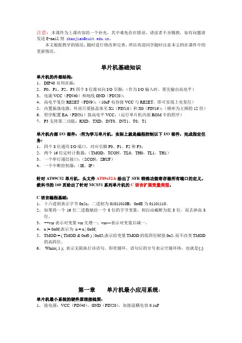
注意:本课件为上课内容的一个补充,其中难免存在错误,请读者不吝赐教,如有问题请发送E-mail到zhaojian@。
本文根据教学的情况,随时进行修改和完善,所以欢迎同学随时注意本文档在课件中的更新情况。
单片机基础知识单片机的外部结构:1、DIP40双列直插;2、P0,P1,P2,P3四个8位准双向I/O引脚;(作为I/O输入时,要先输出高电平)3、电源VCC(PIN40)和地线GND(PIN20);4、高电平复位RESET(PIN9);(10uF电容接VCC与RESET,即可实现上电复位)5、内置振荡电路,外部只要接晶体至X1(PIN18)和X0(PIN19);(频率为主频的12倍)6、程序配置EA(PIN31)接高电平VCC;(运行单片机内部ROM中的程序)7、P3支持第二功能:RXD、TXD、INT0、INT1、T0、T1单片机内部I/O部件:(所为学习单片机,实际上就是编程控制以下I/O部件,完成指定任务)1、四个8位通用I/O端口,对应引脚P0、P1、P2和P3;2、两个16位定时计数器;(TMOD,TCON,TL0,TH0,TL1,TH1)3、一个串行通信接口;(SCON,SBUF)4、一个中断控制器;(IE,IP)针对AT89C52单片机,头文件AT89x52.h给出了SFR特殊功能寄存器所有端口的定义。
教科书的160页给出了针对MCS51系列单片机的C语言扩展变量类型。
C语言编程基础:1、十六进制表示字节0x5a:二进制为01011010B;0x6E为01101110。
2、如果将一个16位二进数赋给一个8位的字节变量,则自动截断为低8位,而丢掉高8位。
3、++var表示对变量var先增一;var—表示对变量后减一。
4、x |= 0x0f;表示为x = x | 0x0f;5、TMOD = ( TMOD & 0xf0 ) | 0x05;表示给变量TMOD的低四位赋值0x5,而不改变TMOD的高四位。
HT16K33A RAM映射LED驱动器说明书

Rev. 1.0012022-05-12HT16K33ARAM 映射16×8 带 按键扫描的LED驱动器特性•工作电压:4.5V~5.5V •内部RC 振荡器 •I 2C 总线接口•16×8位RAM 用于存储显示数据•最大显示模式为16×8:16SEGs 和8COMs •读/写地址自动递增•多达13×3按键矩阵扫描功能 •16阶调光电路•封装类型:20/24/28-pin SOP/SSOP应用领域•工业控制指示器•数字时钟、温度计、计数器、万用表 •机顶盒•录像机设备 •仪表读数•其它消费类应用 •LED 显示概述HT16K33A 是一款存储器映射和多功能LED 控制驱动芯片。
该芯片支持最大128点的显示模式(16SEGs ×8COMs)以及最大13×3的按键矩阵扫描电路。
HT16K33A 的软件配置特性使其适用于多种LED 应用,包括LED 模块和显示子系统。
HT16K33A 通过双向I 2C 接口可与大多数微控制器进行通信。
方框图VDDVSSSDASCLRev. 1.0022022-05-122019181716151413121112345678910VDD SDA SCL ROW0/K1ROW1/K2ROW2/K3ROW3/K4ROW4/K5ROW5/K6ROW6/K7VSS COM0/AD COM1/KS0COM2/KS1COM3/KS2COM4COM5COM6COM7ROW7/K8/INTHT16K33A 20 SOP-A/SSOP-A VDD SDA SCL ROW0/A1ROW1/A0ROW2/K1ROW3/K2ROW4/K3ROW5/K4ROW6/K5ROW7/K6ROW8/K7VSS COM0/AD COM1/KS0COM2/KS1COM3/KS2COM4COM5COM6COM7ROW11/K10/INTROW10/K9ROW9/K8HT16K33A 24 SOP-A/SSOP-A 242322212019181716151413123456789101112VDD SDA SCL ROW0/A2ROW1/A1ROW2/A0ROW3/K1ROW4/K2ROW5/K3ROW6/K4ROW7/K5ROW8/K6ROW9/K7ROW10/K8VSS COM0/AD COM1/KS0COM2/KS1COM3/KS2COM4COM5COM6COM7ROW15/K13/INTROW14/K12ROW13/K11ROW12/K10ROW11/K9HT16K33A 28 SOP-A/SSOP-A28272625242322212019181716151234567891011121314Rev. 1.0032022-05-12内部连接简图极限参数电源供应电压 ..............V SS-0.3V ~ V SS+6.5V 端口输入电压 .............V SS-0.3V ~ V DD+0.3V 工作温度 ................................. -40℃~ 85℃储存温度 ................................-60°C ~ 150°C注:这里只强调额定功率,超过极限参数所规定的范围将对芯片造成损害,无法预期芯片在上述标示范围外的工作状态,而且若长期在标示范围外的条件下工作,可能影响芯片的可靠性。
MAXREFDES1080高光度LED驱动器说明书
IntroductionAs LEDs are becoming more and more popular, so is the need for small, cost-effective solutions. The MAXREFDES1080 is a constant-current, high-brightness LED (HB LED) driver. It delivers 5W of power to a single LED string, which is included in the design. The circuit is in a step-down configuration and is designed for a 12V input. The design uses the MAX16820 controller. This device minimizes the number of external components while delivering constant current over a wide input range. The MAX16820 can operate from a 4.5V to 28V input voltage range and features a 5V/10mA on-board regulator. A hysteretic control algorithm ensures excellent input-supply rejection and fast response during load transients and PWM dimming. These devices operate up to 2MHz switching frequency, thus allowing for small component size.The MAXREFDES1080 delivers power efficiently with a compact solution and low component count. In the current semiconductor industry, where size and component count are becoming more and more important, this circuit effectively delivers the required power for HB LEDs and is perfect for architectural and ambient lighting. The key features are as follows:●5W Output Power●High-Side Current Sense●Adjustable Constant LED Current●±5% LED Current Accuracy●Wide Dimming Range (5000:1)●Dedicated Dimming-Control Input●20kHz Maximum Dimming Frequency●Hysteretic Control: No Compensation●Up to 2MHz Switching Frequency●5V, 10mA On-Board Regulator Hardware SpecificationIn this document, an LED driver using the MAX16820 is demonstrated for a 5V, 1A output application. The driver is in a step-down configuration. Table 1 shows an overview of the design specification.Table 1. Design SpecificationFigure 1. MAXREFDES1080 hardware.Designed – Built – TestedThis document describes the hardware shown in Figure 1. It provides a detailed, systematic technical guide to designing a step-down, constant current LED driver using the MAX16820 controller. The LED driver design has been built and tested, details of which follow later in this document.5V/1A LED Driver in Step-Down,Constant-Current Configuration Using MAX16820MAXREFDES1080Step-Down TopologyThe step-down converter, as seen in Figure 2, is the most commonly used type of switching regulator topology. A step-down converter steps down the voltage from input to output. Most conventional step-down converters consist of two switches (or a switch and a diode), an inductor, a capacitor, and a load (LEDs, in this case). The converter usually also requires a controller to regulate the output. This design uses the MAX16820.Transistor Switch ‘On’ PeriodWhen the transistor switch is on (t ON ), it supplies the output load with current. Initially current flow to the load is restricted, as energy is also being stored in the induc-tor. The current in the load and the charge on the output capacitor, therefore, build up relatively slow in comparison with the switch-on time of the MOSFET. During the ‘on’ period, there is a large voltage across the diode, which causes it to be reverse biased.Transistor Switch ‘Off’ PeriodWhen the transistor switch is off (t OFF ), the energy that had been stored in the inductor’s magnetic field is released. The voltage across the inductor is now in reverse polarity, and sufficient stored energy is available to maintain current flow while the transistor is open. The reverse polarity of the inductor allows current to flow in the circuit through the load and the diode, which is now forward biased. Oncethe inductor has been drained of the majority of its stored energy, the load voltage begins to fall. The charge stored in the output capacitor then becomes the main source of current. This leads to the ripple waveform seen in Figure 3.In this reference design, the circuit is modified to a reverse buck converter topology, as seen in Figure 4. This allows the circuit to operate off of a low-cost, n-channel MOSFET, which reduces BOM cost. The same basic theory is maintained in this topology, except the MOSFET and inductor come after the load.When the MOSFET Q1 is turned ON, current flows through the LEDs and inductor L1, and out through the MOSFET. Energy is stored in the magnetic field generated in the inductor. The current flowing through R SENSE is monitored by the MAX16820 at the CSN pin.Figure 2. Conventional step-down converter topology.Figure 3. Step-down converter waveforms.Figure 4. Reverse buck converter topology.When the MOSFET Q1 is turned OFF, the magnetic field in the inductor begins to collapse and the polarity of the inductor reverses. At the same time the inductor releases its remaining energy to the LEDs and the diode. This maintains constant current in the LEDs.In order to derive the duty cycle equation, first we look at t on , using:L di V Ldt=If integrated between 0 and t on :Lon L onI V Lt ∆=When the switch is on:V L = V IN – V OUTFill into the equation above:IN OUT ONLon(V V )t I L−=∆Now we look at t off , using:L diV Ldt=If integrated between 0 and t off :Lon L offI V Lt ∆=When the switch is off:V L = –V OUTFill into the equation above:OUT OFFLoff(V )t I L−=∆Because the average voltage across the inductor for an entire switching cycle is zero:ΔI Lon = –ΔI LoffFill in the equations above:IN OUT ON OUT OFFIN OUT OUT IN OUT OUT OUT OUT IN(V V )t (V )t L L (V V )DT (V )(1D)TV D V D V V DV D V −−=−−=−−−−=−=Design ProcedureNow that the principle operation of the buck regulator is understood, a practical design example can be illustrat-ed. The converter design process can be divided into three stages: power stage design, MAX16820 controller setup, and current regulation. This document is primarily concerned with the power stage design and the current setting. The design parameters in Table 2 will be used throughout.Step 1: Choosing Inductor L1In the MAXREFDES1080, the minimum inductor value for the circuit is the larger value of:IN LED LED LED LED3.33(V V )L 1.05I or 3.33(V )L 1.05I ×−=××=×L is calculated in μH.The inductor chosen for this design is 56μH.Step 2: Choosing R SENSE to Set theLED CurrentThe MAX16820 features a programmable LED current using a resistor connected between IN and CSN. Use the following equation to calculate the sense resistor:SNSHI SNSLO SENSE LED(V V )1R ()2I +Ω=Typically, V SNSHI = 210mV and V SNSLO = 190mV. For furtherdetails about V SNSHI and V SNSLO , see the Electrical Characteristics in the MAX16820 data sheet .The resistor chosen for this design is a 1%, 0.2Ω resistor.Table 2. Design ParametersStep 3: Determining the Switching FrequencyThe MAX16820 regulates the LED output current using an input comparator with hysteresis. As the current through the inductor ramps up and the voltage across the sense resistor reaches the upper threshold, the voltage at DRV goes low, turning off the external MOSFET. The MOSFET turns on again when the inductor current ramps down through the freewheeling diode until the voltage across the sense resistor equals the lower threshold. Use the following equation to determine the operating frequency:IN LED LED SENSE sw IN SNSHI SNSLO (V V )V R f V (V V )L−××=×−×Where V LED is the forward voltage drop across all LEDs in a string together, and f sw is the switching frequency.Step 4: MOSFET SelectionThe MAX16820’s gate driver is capable of sourcing 0.5A and sinking 1A of current. MOSFET selection is based on the maximum input operating voltage V IN , output current I LED , and operating switching frequency. For better effi-ciency, choose a MOSFET that has a higher breakdown voltage than the maximum input voltage, low R DS(ON), and low total charge. The MOSFET threshold voltage must be adequate if operated at the low end of the input-voltage operating range.The MOSFET chosen for this design is the Fairchild Semiconductor FDN359BN n-channel MOSFET.Design ResourcesDownload the complete set of Design Resources including the schematics, bill of materials, PCB layout, and test files.Step 5: Freewheeling Diode SelectionThe forward voltage of the freewheeling diode should be as low as possible for better efficiency. A Schottky diode is a good choice as long as the breakdown voltage is high enough to withstand the maximum operating voltage. The forward current rating of the diode must be at least equal to the maximum LED current.The diode chosen for this design is the Fairchild Semiconductor FBR130 Schottky diode.Step 6: LED Current RippleThe LED current ripple is equal to the inductor current rip-ple. In cases when a lower LED current ripple is needed, a capacitor can be placed across the LED terminals.Step 7: DIM InputThe MAX16820 allows dimming with a PWM signal at the DIM input. A logic level below 0.6V at DIM forces the MAX16820’s DRV output low, turning off the LED current. To turn the LED current on, the logic level at DIM must be at least 2.8V.NoteThe MAXREFDES1080 board is not thermally optimized for the LED components used.Revision HistoryMaxim Integrated cannot assume responsibility for use of any circuitry other than circuitry entirely embodied in a Maxim Integrated product. No circuit patent licenses are implied. Maxim Integrated reserves the right to change the circuitry and specifications without notice at any time. The parametric values (min and max limits) shown in the Electrical Characteristics table are guaranteed. Other parametric values quoted in this data sheet are provided for guidance.© 2019 Maxim Integrated Products, Inc. All rights reserved. Maxim Integrated and the Maxim Integrated logo are trademarks of Maxim Integrated Products, Inc., in the United States and other jurisdictions throughout the world. All other marks are the property of their respective owners.Maxim Integrated。
按键扫描与LED显示驱动芯片ET6218R芯片资料
ET6218REtekMicroelectronics LED Controller/driverGeneral DescriptionET6218R is an LED Controller driver on a 1/7 to 1/8 duty factor. 7 segment output lines, 4 grid output lines, 1 segment/grid output lines, one display memory, control circuit, key scan circuit are all incorporated into a single chip to build a highly reliable peripheral device for a single chip microcomputer. Serial data is fed to ET6218R via a three-line serial interface, ET6218R pin assignments and application circuit are optimized for easy PCB Layout and cost saving advantages.Featuresz CMOS Technologyz Low Power Consumptionz Multiple Display Modes(4~5 Grid, 7~8 segment) z Key scaning(7×1 Matrix) z 8-step Dimming Circuitryz Serial Interface for Clock, Data Input/Output, Strobe Pins zAvailable in 18-pin, DIP PackagePin ConfigurationsPin DescriptionPin No.Pin NameI/ODescription5 DI/O(DIN&DOUT) I/OData I/O Pin(N-channel, Open-Drain)This pin outputs serial data at the falling edge of the shift clock andinputs serial data at the rising edge of the shift clock(starting from the lower bit)6 CLK I Clock Input PinThis pin reads serial data at the rising edge and outputs data at thefalling edge7 STB I Serial Interface Strobe PinThe data input after the STB has fallen is processed as a commandWhen this pin is “HIGH”, CLK is ignored 8 K1 I Key Data Input PinsThe data sent to these pins are latched at the end of the display cycle(Interface Pull-Low Resistor)2 GND ─ Ground Pin10~16 SG1/KS1~SG7/KS7 O Segment Output Pins(p-channel, open drain) Also acts as the Key Source 17 SG14/GR5 O Segment/Grid Output Pins 9 VDD ─ Power Supply 1,3,4,18 GR4~GR1 O Grid Output PinsINPUT/OUTPUT CONFIGURATIONSThe schematic diagrams of the input and output circuits of the logic section are shown below. 1. Input Pins :CLK ,STB&DIN(DI/O)2.Input Pins:K13.Output Pins:DOUT(DI/O),GR1~GR44.Output Pins:SG1~SG75.SG14/GR5Block DiagramFunctional DescriptionCOMMANDSA command is the first byte(b0~b7) inputted to ET6218R via the DI/O Pin after STB Pin has changed from HIGH to LOW State. If for some reason the STB Pin is set to HIGH while data or commands are being transmitted, the serial communication is initialized, and the data/commands being transmitted are considered invalid.Command 1:Display Mode Setting CommandsET6218R provides 2 display mode settings as shown in the diagram below:As started earlier a command isthe first one byte(b0~b7) transmitted to ET6218R via the DI/O Pin when STB is LOW. However, for these commands,the bit 3 to bit 6(b2~b5)are ignored,bit 7&bit 8(b6~b7) are given a value of 0.The Display Mode Setting Commands determine the number of segments and grids to be used (7 to 8 segments,4 to 5 grids). A display command ON must be excuted in order to resume display. If the same mode setting is selected, no command execution is take place, therefore, nothing happens. When Power is turned ON,the7-grid, 10-segment modes is selected.MSB LSB0 0 ──── b1 b0 b2~b5:Not RelevantDisplay Mode Setting:b1,b0—0 0:4 Grids,8 Segmentsb1,b0—0 1:5 Grids,7 SegmentsCommand 2:Data Setting CommandsData Setting Commands executes the Data Write or Data Read Modes for ET6218R. The data Setting Command, the bits 5 and 6(b4,b5) are ignored, bit 7(b6) is given the value of 1 while bit 8(b7) is given the valueof 0. Please refer to the diagram below. When Power is turned ON, bit 4 to bit 1(b3~b0) are given the value of 0.MSB LSB0 1 ──b3b2b1 b0 b4,b5:Not RelevantMode Setting: b3 —0:Normal OperationMode b3—1:Test ModeAddress Increment Mode Settings(Display Mode):b2—0:Increment Address after Data has been Writtenb2—1:Fixes AddressData Write&Read Mode Setting:b1,b0—0 0:Write Data to Display Modeb1,b0—1 0:Read Key DataET6218R KEY MATRIX&KEY INPUT DATA STORAGE RAMET6218R Key Matrix consists of 7×1 array as shown below:Each data entered by each key is stored as follows and read by a READ Command, starting from the lastCommand 3:Address Setting CommandsAddress Setting Commands are used to set the address of the display memory. The address is considered valid if it has a value of 00H to 0DH. If the address is set to 0EH or higher,the data is ignored until a valid addressis set. When power is turned ON,the address is set at 00H.MSB LSB1 1 ──b3b2b1 b0 b4,b5:Not RelevantThe address of b3~b0:00H~0DHDISPLAY MODE AND RAM ADDRESSData transmitted from an external device to ET6218R via the interface are stored in the Display RAM andare assigned address. The RAM addresses of ET6218R are given below in 8 bits unit.SG1…………SG4 SG5…………SG8 SG9…………SG12SG13…………SG1400H L 00H U 01H L 01H U DIG1 02H L 02H U 03H L 03H U DIG2 04H L 04H U 05H L 05H U DIG3 06H L 06H U 07H L 07H U DIG4 08H L 08H U 09H L 09H U DIG5 b0…………….b3 b4………………b7xxH L xxH ULower 4 bits Higher 4 bitsCommand 4:Display Control CommandsThe Display Control Commands are used to turn ON or OFF a display. It also used to set the pulse width.Please refer to the diagram below. When the power is turned ON,a 1/16 pulse width is selected and the displayedis turned OFF(the key scaning is stopped).MSB LSB1 0 ──b3b2b1 b0b4,b5 :Not RelevantDisplay Setting: b3—0:Display OFF(Key Scan Continues)b3—1:Display ONDimming Quantity Setting:000:Pulse width=1/16001:Pulse width =2/16010:Pulse width =4/16011:Pulse width =10/16100:Pulse width =11/16101:Pulse width =12/16110:Pulse width =13/16111:Pulse width =14/16SCANNING AND DISPLAY TIMINGThe Key Scanning and Display Timing diagram is given below. One cycle of key scanning consists of 2SERIAL COMMUNICATION FORMATThe following diagram shows the ET6218R serial communication format.The DI/O(DIN,DOUT) Pin is an N-channel,open-drain pin, therefore, it is highly recommended that an external pull-up resistor(1K~10K) must be connected to DI/O.waitIt must be noted that when the data is read, the waiting time(twait) between the rising of the eighth clock that has set the command and the galling of the first clock that has read the data is greater or equal to 1µs.SWITCHING CHARACTERISTIC WA VEFORMCLK STBt setup(Data Setup Time)≥100ns t hold(Data Hold Time)≥100nst CLK-STB(Clock-Strobe Time)≥1µs t THZ(Fall Time)≤10µst TZH(Rise Time)≤1µs t PZL(Propagation Delay Time)≤100ns fosc=Ocillation Frequency t PLZ(Propagation Delay Time)≤300ns t TZL<1µs t TLZ<10µsNote:Test condition undert THZ(Pull low risistor=10kΩ,Loading capacitor=300pf)t TLZ(Pull low risistor=10 kΩ,Loading capacitor =300pf)APPLICATIONCommand 2:Data Setting CommandCommand 3:Address Setting CommandData 1~n:Transfer Display Data(14 Bytes max) Command 4:Display Control CommandNote:1. Command 1:Display Mode Commands2. Command 2:Data Setting Commands3. Command 3:Address Setting Commands4. Command 4:Display Control CommnadsWhen IC power is applied for the first time, the contents of the Display RAM is not defined; thus, it is strongly suggested that the contents of the Display RAM must be cleared during the initial setting.Absolute Maximum Ratings(Ta = 25℃,GND = 0V)Parameter Symbol Ratings UnitSupply V oltage V DD-0.5~+7 VLogic Input V oltage V I-0.5~V DD+0.5 VDriver Output Current I OLGR +250 mA I OHSG -50 mAMaximum Driver Output Current/Total I TOTAL 400 mA Operating Temperature T opr-40~+85 ℃Storage Temperature T stg-55~+150 ℃Recommended Operating Range(Ta = -20~+70℃,GND = 0V)Parameter Symbol Min. Typ. Max. Unit Logic Supply V oltage V DD 3 5 5.5 V Dynamic Current(see Note)I DDdyn—— 5 mA High-Level Input V oltage V IH 0.6V DD—V DD VLow- Level Input V oltage V IL 0 —0.3V DD V Note:Test Condition:Set Display Control Commands=80H(Display Turn OFF State&under no load)Electrical Characteristics(V DD = 5V,GND = 0V,Ta = 25℃)Parameter Symbol Test Condition Min. Typ. Max.UnitHigh-Level Output Current I OHSG1V O =V DD-2V,SG1~SG7,SG14-20 -25 -40 mA I OHSG2V O =V DD-3V,SG1~SG7,SG14-25 -30 -50 mALow-Level Output Current I OLGR V O =0.3V,GR1~GR5, 100 140 —mA Low-Level Output Current I OLDOUT V O =0.4V 4 ——mASegment High-Level Output Current Tolerance I TOLSGV O =V DD-3V,SG1~SG7,SG14——+5 %High-Level Input V oltage V IH—0.6V DD— 5 VLow-Level Input V oltage V IL—0 —0.3V DDVOscillation Frequency fosc 350 500 650 kHz K1 Pull Down Resistor R KN V DD=5V 40—100 kΩ(V DD =3V , GND=0V , Ta=25℃)Parameter Symbol Test Condition Min. Typ. Max.Unit High-Level Output Current I OHSG1 V O = V DD -2V ,SG1~SG7,SG14-15 -20 -35 mALow-Level Output CurrentI OLGR V O =0.3V ,GR1~GR5, 100 140 — mA Low-Level Output Current I OLDOUT V O =0.4V 4 — — mASegment High-Level Output Current Tolerance I TOLSG V O = V DD -3V ,SG1~SG7,SG14— — +5% High-Level Input V oltage V IH — 0.8V DD—3.3 V Low-Level Input V oltage V IL — 0 — 0.3V DDVOscillation Frequency fosc 300 420 580 kHz K1 Pull Down ResistorR KN V DD =3V 40 —100 k Ω Application CircuitCOMMON CATHODE TYPE LED PANELNote :1. The capacitor(0.1µF)connected between the GND and VDD pins must be located as close as possible to the ET6218R chip.Package Dimension。
笔记本硬盘_光驱接口定义
笔记本硬盘接口定义笔记本光驱接口定义笔记本光驱接口定义01.RESET# 02.GND03.D7 04.D805.D6 06.D907.D5 08.D1009.D4 10.D1111.D3 12.D1213.D2 14.D1315.D1 16.D1417.D0 18.D1519.GND 20.未用21.GND 22.GND23.HIOW 24.GND25.HIOR 26.GND27.IOCHRDY 28.HALE29.DAKS 30.GND31.IRQBUS 32.IOCS1633.A1 34.未用PDIAG35.A0 36.A237.HCS0 38.HCS139.DASP 40.GND41.+5V逻辑电源(驱动电路板) 42.+5V(给电机供电)43.GND 44.NC45. 46.47.D 48.C49.B 50.A2.5英寸笔记本硬盘一般使用50针接口,其中41针一般为驱动逻辑(电路板)提供+5V电压,42针为电动机提供+5V电压(笔记本硬盘用+5V电机,台式机硬盘用+12V电机)数据D0-D15是主机和驱动器之间的双向传输线RESET#是上电时主机送来的信号,使驱动器复位,其后保持高电平写选通HIOW:当低电平有效时,把主机送来的数据写入寄存器或驱动器的数据寄存器读选通HIOR:当低电平有效时,读某个寄存器或驱动器的数据寄存器地址锁存允许HALE:用于锁存地址信号中断请求IRQBUS:驱动器向主机发送中断请求信号I/O芯片选中IOCS16:它通知主机,16位寄存器已经选中,驱动器准备发送或接收16位数据地址信号A0-A2片选HCS0,HCS1:是主机地址译码后得到的片选信号,选择可直接存取的寄存器。
笔记本的硬盘接口引脚定义:文字描述:Pin Name Dir Description1 /RESET Reset2 GND Ground3 DD7 Data 74 DD8 Data 85 DD6 Data 66 DD9 Data 97 DD5 Data 58 DD10 Data 109 DD4 Data 410 DD11 Data 1111 DD3 Data 312 DD12 Data 1213 DD2 Data 214 DD13 Data 1315 DD1 Data 116 DD14 Data 1417 DD0 Data 018 DD15 Data 1519 GND Ground20 KEY - Key21 n/c - Not connected22 GND Ground23 /IOW Write Strobe24 GND Ground25 /IOR Read Strobe26 GND Ground27 IO_CH_RDY28 ALE Address Latch Enable29 n/c - Not connected30 GND Ground31 IRQR Interrupt Request32 /IOCS16 ? IO ChipSelect 1633 DA1 Address 134 n/c - Not connected35 DA0 Address 036 DA2 Address 237 /IDE_CS0 (1F0-1F7)38 /IDE_CS1 (3F6-3F7)39 /ACTIVE Led driver40 GND Ground41--44是电源:41,42: +5V,43,44:接地。
创维B28E220E液晶彩电维修手册
TABLE OF CONTENTSPAGE 1.PRECAUTION AND NOTICES ------------------------------------------------------------------------------------- 11.1.SAFETY PRECAUTIONS ---------------------------------------------------------------------------------------- 11.2.PRODUCT SAFETY NOTICE ----------------------------------------------------------------------------------- 11.3.SERVICE NOTES -------------------------------------------------------------------------------------------------- 12.SERVICE TOOL & EQUIPMENT REQUIRED ---------------------------------------------------------------- 23.SPECIFICATIONS ----------------------------------------------------------------------------------------------------- 2~33.1.Diagram ------------------------------------------------------------------------------------------------------------- 23.2.PRODUCT SPECIFICATIONS ---------------------------------------------------------------------------------- 33.3.Function of Board ------------------------------------------------------------------------------------------------- 33.4.Part apt to decrease ----------------------------------------------------------------------------------------------- 34.EXPLODED VIEW AND PARTS LIST --------------------------------------------------------------------------- 44.1.EXPLODED VIEW ------------------------------------------------------------------------------------------------ 45.BLOCK DIAGRAM ---------------------------------------------------------------------------------------------------- 56.Main Board Service Chart -------------------------------------------------------------------------------------------- 6~106.1Main Board and connector definition ------------------------------------------------------------------------- 66.2Main Board --------------------------------------------------------------------------------------------------------- 6~76.3Main Board interface definition -------------------------------------------------------------------------------- 8~107.SCHEMATIC DIAGRAM -------------------------------------------------------------------------------------------- 11~128.PCB LAYOUT ----------------------------------------------------------------------------------------------------------- 139.TROUBLE SHOOTING FLOW CHART ------------------------------------------------------------------------- 14~2210.Some signals waveform for reference ------------------------------------------------------------------------------- 23~2508/04/20151. PRECAUTION AND NOTICES1.1. SAFETY PRECAUTIONSThis TV is manufactured and tested on a ground principle that a user's safety comes first.However, improper use or installation may cause damage to the TV as well as to the user.Carefully go over the following WARNINGS before installing and keep this guide handy .WARNINGS:This TV should be operated only at the correct power sources indicated on the label on the rear end of the TV. If you're unsure of the power supply in your residence, consult yourlocal dealer or power company.Use only the special power adapter that comes with this TV for power input.Do not try to repair the TV your self as it contains no user-serviceable parts. This TV should only be repaired by a qualified technician.Do not remove the TV cabinet. There is high-voltage parts inside that may cause electric shock to human bodies, even when the power cord is unplugged.Stop using the TV if the cabinet is damaged. Have it checked by a service technacian.Put your TV only in a clean, dry environment. If it gets wet, unplug the power cable immediately and consult your service technician.Always unplug the TV before cleaning it. Clean the cabinet with a clean, dry cloth.Apply non-ammonia based cleaner onto the cloth, not directly onto the glass screen.Keep the TV away from magnetic objects, motors, and transformer.Do not place heavy objects on the TV or power cord.1.2. PRODUCT SAFETY NOTICEMany electrical and mechanical parts in this chassis have special safety visual inspectionsand theprotection afforded by them cannot necessarily be obtained by using replacementcomponents rated for higher voltages, wattage, etc. Before replacing any of thesecomponents read the parts list in this manual carefully. The use of substitute replacementparts which do not have the same safety characteristics as specified in the parts list maycreate shock, fire, or other hazards.1.3. SERVICE NOTES1. When replacing parts or circuit boards, clamp the lead wires around terminals beforesoldering.2. Keep wires away from high voltage, high temperature components and sharp edges.3. Keep wires in their original position so as to reduce interference.4. Usage of this product please refer to also user's manual.-1-08/04/20152. SERVICE TOOL & EQUIPMENT REQUIRED1. SIGNAL GEN.2. MULTIMETER3. OSCILLOSCOPE4. SCREW DRIVER5. IRON6. ABSORBER7. SOLDER3. SPECIFICATIONS3.1. Diagram-2-08/04/20153.2. PRODUCT SPECIFICATIONSPanel BOEI280WX1 HV280WX2-270Displayable Resolution FHD 1366*768Pixel Pitch 148.25(H)× 449.25(V) × RGBLCD Display Color 16.7M Color Max.Viewing Angle Horizontal: 65°Vertical: 60°Contrast Ratio 1000:1(typical) 900:1(MIN)Brightness 200cd/ m2 (min.)220cd/m2 (typ.)Panel Brightness*: TV SET Brightness will lower than Panel Brightness because of PictureQuality and White Balance affection.Response Time Tr+Tf: 8.0ms(typ.) Tr+Tf: 10ms(max.)Temperature Operating: 0°C ~ +40°CStorage: -20°C ~ +60°CPower Input Voltage: 100~264 VacConsumption: 65 Watts (Max.)3.3 Function of Board1) Main Board: Control all input signals, Decode the video signal,De-interlace, and send digital signals (LVDS signal) sent from image Board and display; supply LCM backlight power2) Panel: Display all images;3) IR Board: Receive remote operation;4) Key Board : buttons of POWER、 SOURCE、 MENU、 VOL+/- ,Channel +/-;5) AC Input: 200~240 Vac;3.4 Part apt to decrease1) Bezel, Rear Cover and Panel;2) Terminal of all plugs.-3-08/04/20154.1. EXPLODED VIEW5. BLOCK DIAGRAM6. Main Board Service Chart6.1 Main Board and connector definition6.2Main Board-6-08/04/2015-7-08/04/20156.3Main Board interface definitiona. KEY&IR BOARD CONNECTOR(14PIN/2.0)-8-08/04/2015b. LVDS INTERFACE(2×15PIN/2.0)c.LED BACKLIGHT MODULE CONNECTOR(3PIN/2.0MM)-9-08/04/2015B28E220E Service Manuald.SPEAKER CONNECTOR(4PIN/2.54)-10-08/04/20157. SCHEMATIC DIAGRAMFor V59CW910RW9288. PCB LAYOUT9. TROUBLE SHOOTING FLOW CHART9.1 Power Board Diagram-14-08/04/20159.2AC-DC Power Supply Trouble-15-08/04/20159.3Power Supply Trouble-16-08/04/20159.4 Display Trouble(black screen)-17-08/04/20159.5 Audio Trouble(No sound)-18-08/04/20159.6 Function Trouble(TV video)-19-08/04/20159.1.1 Function Trouble(PC)-20-08/04/20159.1.2 Function Trouble(SCART、HDMI、YPbPr、CVBS)-21-08/04/2015-22-08/04/201510. Some signals waveform for reference-23-08/04/2015-24-08/04/2015-25-08/04/2015。