
三星 788DF说明书
在没有显示器支架时不要使用显示器。 z 由于通风不好有可能不工作甚至起火。 z 如果显示器必须在不带所提供的支架的情况下工作,那麽一定要采取措施 保证适当的通风。
在安装本产品时,出于保持通风之目的,请确保将它与墙壁隔开一段距离 (大于 10 厘米/4 英寸)。
z 通风条件不良,可使本产品内部温度升高,从而缩短部件寿命和降低产品 性能。
SyncMaster 788DF
驱动程序安装
程序安装
符号
若不按照这个符号所指出的方向,就可能造成对人体的伤害或者对设备的破坏。
禁止的 不要拆开 不要碰
任何时候阅读并理解都很重要 从插座上拔下插头 接地以避免电击
电源
在长时间不使用计算机的情况下,请设置屏幕保护程序。 z 如果同一画面显示时间太久,可能会发生荧光粉灼烧或屏幕变得模糊不清。
7.
打开电脑和显示器。
8.
上下调节显示器台座上的音量开(ON)/关(OFF)。
9.
打开电脑的音响程序、音乐或音响效果,慢慢地上下调节,使声音的大小达到最佳状态。
10. 调节高音和低音。
声音的浑浊现象,是将显示器直接放在譬如电脑能够引起回音的物体上时,可能发生的现象。 这种情况时,请在显示器台座下面放入杂志或垫板等使用。在高音时可出现声音刺耳现象,请 降低音量使用。
不要使用损坏了的或松动了的插头。
z 这会引起电击或起火
不要去拉电线来试图拔出插头,也不要用湿手去触摸插头。 z 这会引起电击或起火。
只使用适当接了地的插头和插座。 z 接地不好可能造成电击或设备损伤。
将电源插头插紧以防松脱。 z 连接不好可能导致起火。
不要过度地弯曲插头和电线,也不要在它们上面放置重物,这样可能造成损伤。 z 不照这样做可能造成电击或起火。
/ (中国单独) Windows ME
1. 将CD放入CD-ROM驱动器中。 2. 点击 "Windows ME Driver"。 3. 在型号列表中选择你的显示器的型号,然后点击"OK" 按钮。
4. 在警告窗口中点击 安装 按钮。
5. 显示器驱动器的安装(Monitor Driver Installation)完成。 Windows XP/2000
在把机座装到显示器上去之前要把紧部分松开。
装上基座 1. 把显示器上下倒置在一个平整的工作面上。 2. 让基座上的小突起与显示器底部上相应的槽口对齐。 3. 把基座往显示器上按,直到小突起完全插进到槽口里为止。 4. 把基座推向显示器的前方,直到释放锁咔嚓一响进入到锁定位置。 * 不要弯曲扣锁。
拿掉基座 5. 挤压并上拉基座上的释放锁。 6. 把基座推向显示器的背面并往上提来拿开基座 只有在一个位置上基座与显示器才能对齐。
在一个插座上不要连接太多的插销板或插头。 z 这可能引发火灾。
安装
如果要将产品安装到多尘、高温或低温、湿度过高、存在化学物质以及 24 小时连续 使用本产品(如机场和车站等)的环境中,请一定与经授权的服务中心联系。 否则,安装不当会对显示器造成严重损坏。
把你的显示器放在一个湿度低而且灰尘尽量少的地方。 z 可能在显示器的内部产生电击或起火。
在搬动显示器时小心不要摔下来。
z 这会对产品造成损伤或者会伤着人。
将显示器基座安装到陈列柜或搁板,以免其基座末端从陈列柜或隔板凸出。 z 本产品坠落可能会导致产品损坏或人身伤害。
不要将本产品放置在不稳或窄小的表面上。 z 请将本产品放置在平整、稳固的表面上,以防坠落伤人(特别是小孩)。
不要将本产品放在地板上。 z 可能有人(特别是小孩)会被绊倒。
安装视频驱动程序
当操作系统提示出要显示器驱动程序时,插入显示器所带的光盘。对不同的操作系统来说,驱 动程序的安装会略有不同。按照适合你的操作系统的指示去做。 准备好一张空白盘,将下面给出的互联网网站上的驱动程序文件下载下来。 z 互联网网站 : / (全世界)
z 否则可能会将显示器损坏,导致失火或电击。
请将本产品放在小孩碰不到的地方,以免他们攀爬而损坏本产品。 z 本产品坠落时可能导致人身伤害甚至死亡。
如果较长时间不使用本产品,请拔下电源线。 z 否则可能因积尘或绝缘老化而发热,从而导致触电或起火。
不要将小孩喜欢的物品(或其他任何吸引小孩的东西)放在本产品上。 z 小孩可能会为了拿到该物品而试图攀爬本产品。本产品可能会坠落而造成 人身伤害,甚至死亡。
清洁本产品前请务必拔下电源线。 z 否则可能导致触电或起火。
从电源插座中拔出电源线后用柔软的干布擦拭本产品。 z 千万不要使用蜡、苯、酒精、稀释剂、杀虫剂、空气清新剂、润滑剂或清 洁剂等任何化学品。
每年请与维修中心或者客户服务中心联系一次,对产品内部进行清洁。 z 产品内部须保持清洁。因时间较长而导致灰尘在产品内部蓄积,可能会引 发故障或失火。
(STAND)背部的音响输入部位(STEREO INPUT)。
剩下的语音电缆的一端连接在音卡或电脑线输出部位,另一端连接在显示器台座后部的辅助麦
克(Mic By-Pass)部位。
4.
将直流电源插头连接在台座(STAND)的直流(DC)12V端口。
5.
将电源插头连接在显示器背部电源连接端口。
6.
将电脑和显示器的电源插头插入220V或110V专用插座。(电压自动调节)
其他
不要打开护盖(或后盖)。 z 这会造成电击或起火。 z 要让合格的维修人员来维修。
如果你的显示器工作不正常—特别是当有任何异常的声音或气味从显示器里出 来的话—要立即拔下插头,并与一个授权的经销商或服务部门联系。
z 这有可能造成电击或起火。
不要将本产品放置在有油、烟或潮湿的地方;也不要将其安装在车辆上。 z 这样可能会导致故障、电击或者失火。 z 要特别避免在水旁或可能会暴露在雨雪中的户外地方操作显示器。
不要只是拉动电线或信号电缆来使显示器左右移动。 z 这样由于会损坏电线而造成破坏、电击或起火。
不要盖住显示器机壳上的通风口。 z 通风不好可能会使工作停止甚至会起火。
不要在显示器上放置一杯水、化学品、或者任何小的金属物体。 z 这有可能造成损伤、电击或起火。 z 如果有外部的东西进入了显示器,请拔下插座,然后与服务中心联系。
“进入”按钮。 [ ]
电源按钮[ ]
电源指示灯
打开 OSD 菜单。也用于退出 OSD 菜单或回到上一菜单。
这些按钮让你选择突出并调整菜单里的一些项目。 用于选择 OSD 菜单 使用这个按钮来打开或关闭显示器。 表示正常模式ห้องสมุดไป่ตู้节电模式。
有关节电功能的进一步信息请看手册里说明的节电器。为了节省能源,在不需要它,或长时 间不去看它的时候,请把你的显示器关掉。
如果显示器坠落或者铸件被毁坏,将显示器关闭,并拔下电源线的插头。 然后 与维修中心联系。
z 显示器可能会发生故障,导致电击或失火。
在暴风雨或雷电期间,或者要有相当长一段时间不用时,请把插头从插座上拔 下。
z 如果不这样做,有可能造成电击或起火。
不要试图用拉电线或信号电缆的办法来移动显示器。 z 这样由于会损坏电缆而造成破坏、电击或起火。
2-3. 如果是老型号的苹果电脑,您需要用特殊的苹果适配器连接到监视器上。
3. 打开你的计算机和显示器。如果你的显示器显示出图像,那麽安装就完成了。
电缆连接- 多媒体显示器
1.
关闭电脑,拔掉电源插头。
2.
用电脑连接电缆连接显示器和电脑。(影像板、影像卡或图卡)
3.
语音电缆的一端连接在音响(SOUND)卡或电脑的音响输出部位,另一端连接在显示器台座
清洁
在清洁显示器的机箱或显像管的表面时,要用一块稍稍润湿了的软纤维布来擦 拭。 不要用水来清洁显示器。要用水稀释了的柔和的洗涤剂。 (有些洗涤剂包含大量基于酒精的溶剂,这会损坏(颜色改变)显示器机箱或使它 开裂。 显像管上的防眩光/抗静电的表面镀膜也会受到影响。) 使用前先用水稀释洗涤剂 (1:10的比例)。
多媒体台座
1. 辅助麦克连接部分(MIC BY-PASS) 为传出语音,在辅助麦克连接部分和位于电脑上的麦 克连接部分连接语音电缆。
2. 音响输入部分(STEREO INPUT) 将音卡、电脑、CD-ROM驱动器等用语音电缆连接在 音响输入部分。
3. 电流电源连接部分(DC INPUT 12V 1A)
1. 将CD放入CD-ROM驱动器中。 2. 点击 "Windows XP/2000 Driver"。 3. 在型号列表中选择你的显示器的型号,然后点击"OK" 按钮。
4. 如出现如下的 "信息" 窗,则选择 "继续" 按钮,然后 "确认" 。
此显示器驱动器已得到MS商标认可,驱动器的安装不会给您的操作系统造成损伤。 您可在三星显示器网站 /中查询获得认证的显示器。
后面板
电源端口 信号电缆
(每个显示器的后面板配置有可能不同。)
把你的显示器的电源线连接到显示器背面的电源端口。 把信号电缆的一端连到你的计算机的视频口、视频板、视频卡或 图形卡。
关于电缆连接的进一步信息请看连接你的显示器。
底部
倾斜/转动基座
你可以把基座与显示器分开。
访问我们的网站并下载 MagicTune, Natural Color Windows 的安装软件。
8. 麦克连接部分 为传出语音,将麦克连接在麦克插入部分。
9. 头戴式耳机连接部分
10. 台座的最上端
基座安装
倾斜/转动基座 | 安装和拆卸支架
倾斜/转动基座
由于有内建的轴架,你可以倾斜和/或转动显示器来达到最舒服的观看角度。
支架同显示器连在一起。 安装和拆卸支架 如果提供给你的显示器是与基座分开的,那麽按如下步骤装上基座:
为减轻眼睛疲劳,在使用显示器时,须每小时休息五分钟时间。
三星电子产品说明书

396438 Spring (72 req’d) 382716 Guide (72 req’d)
Snap Ring (2 req’d) (See table)
423410 Pin
Y 154108 O-Ring (4 req’d)
Pack with grease at assembly
Y 271822 Back-up Ring (4 req’d)
382709 Rotor
Y 1623 Seal (2 req’d) Y 154011 O-Ring (2 req’d)
Y 154130 O-Ring
181792 Plug
Ring (See Table)
CAUTION Assemble Ring with Case Drain Hole as shown (not rotated with hole at top)
Service Data
Vickers®
Vane Motors
Multi-Torque Vane Motors
MHT-190 and 220 Series
Model MHT-190/N1-30-S20 MHT-190/R1-30-S20 MHT-220/N1-30-S20 MHT-220/R1-30-S20
resistant fluids
2 Model Series MHT - Vane motor, high torque,
low speed
4 Shaft
N1 - No shaft R1 - Standard solid shaft
3 Theoretical Torque
Combinations of theoretical output torque in lbs. ft. per 100 p.s.i. differential pressure
Samsung 7.4 cu. ft. 电子气干衣机说明书
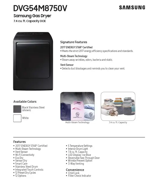
DVG54M8750VSamsung Gas Dryer7.4 cu. ft. Capacity DOESignature Features2017 ENERGY STAR ® Certifi ed • M eets the strict 2017 energy efficiency specifications and standards. Multi-Steam Technology • S team away wrinkles, odors, bacteria and static.Vent Sensor • D etects duct blockages and reminds you to clean your vent.Multi-Steam Technology7.4 cu. ft. Capacity• 2017 ENERGY STAR ® Certifi ed • M ulti-Steam Technology • V ent Sensor • W i-Fi Connectivity • E co Dry • S ensor Dry • Smart Care• Stainless Steel Drum• Integrated Touch Controls • 12 Preset Dry Cycles • 12 Options• 5 Temperature Settings• I nterior Drum Light • 7.4 cu. ft. Capacity • LED Display: Ice Blue• Reversible See-Through Door • Wrinkle Prevent Option • 3-Way VentingConvenience• Child Lock• Filter Check IndicatorAvailable ColorsBlackActual color may vary. Design, specifications, and color availability are subject to change without notice. Non-metric weights and measurements are approximate.©2018 Samsung Electronics America, Inc. 85 Challenger Road, Ridgefield Park, NJ 07660. Tel: 800-SAMSUNG. . Samsung is a registered trademark of Samsung Electronics Co., Ltd.3-Way Venting12 Preset Dry Cycles:Steam Refresh, Steam Sanitize, Steam Wrinkle Away, Normal, Heavy Duty, Permanent Press, Bedding, Delicates, Active Wear, Time Dry, Air Fluff, Quick Dry 12 Options:Mixed Load Bell, Wrinkle Prevent, Adjust Time (Up), Adjust Time (Down), My Cycle, Child Lock,Sound On/Off, Anti-Static, Eco Dry, Smart Care, Drum Light, Smart Control5 Temperature Settings:High, Medium, Medium Low, Low, Extra Low 5 Dry Levels:Very Dry, More Dry, Normal Dry, Less Dry, Damp Dry2 Sound Level Settings: On/OffWarrantyOne (1) Year Parts and LaborProduct Dimensions & Weight (WxHxD)Dimensions: 27" x 427/16" x 301/4"Weight: 121.3 lbsShipping Dimensions & Weight (WxHxD)Dimensions: 299/16" x 455/8" x 313/16"Weight: 130.1 lbsGas Model # UPC Code Black Stainless Steel DVG54M8750V 887276197043White DVG54M8750W 887276197050 ElectricBlack Stainless Steel DVE54M8750V 887276197005White DVE54M8750W 887276196893Matching WasherBlack Stainless Steel WA54M8750AV 887276196466 White WA54M8750AW 887276196473DVG54M8750VSamsung Gas Dryer7.4 cu. ft. Capacity DOERecessed AreaSide View Confined22Sides – 1" Top – 21"Rear – 6"Closet Front – 2"Minimum clearances for closets and alcoves:If the washer and dryer are installed together , the closet front must have at least a 72-inch 2 unobstructed air opening. Your washer alone does not require a specific air opening.*Required spacing (External exhaust elbow may require additional space.)DimensionsAlcove or closet installationInstallation Specifications**Adjustable height depending on leveling feet.。
SAMSUNG SGH-X478 手机 说明书

安全措施
如未遵守以下注意事项,可能会引起危险 或违反法律。
交通安全第一 在驾车时不要使用手机。如要通话,请先停车。
加油时关机 在加油站 (维修站)或靠近易燃物品、化学制剂的地 方,请勿使用手机。
乘坐飞机时要关机 移动电话会造成干扰,在飞机上使用手机不仅危险而且 是违法的。
来电铃声
1. 在待机模式下,按下 < 功能表 >, 并选择声音设定 → 响铃类型。
2. 选择音乐铃声。
待机屏幕墙纸
可使用各种图片设定为待机屏幕墙纸。 1. 在待机模式下,按下 < 功能表 >,
并选择话机设定 → 显示屏设定 → 墙纸 → 墙纸列表。
2. 滚动选择所需图片。
3. 按下 < 选择 >。
切换到静音模式
3 网络服务
1 呼叫转移 2 呼叫限制 3 呼叫等待 4 网络选择 5 主叫号码限制 6 用户群
26 页
26 页
26 页 26 页 26 页 26 页 27 页 27 页
27 页
28 页 28 页 29 页 29 页 29 页 29 页
4 声音设定
1 响铃类型 2 响铃音量 3 振铃类型 4 按键音 5 信息提示音 6 翻盖铃声 7 开 / 关机 8 整点报时 9 通话中提示 0 其它提示音
1 WAP 浏览器 2 三星乐园 3 游戏及其它 4 铃声 5 图片 6 全部删除 7 乐曲编辑器 8 存储器状态
7 管理目录
1 闹钟 2 日历 3 时间和日期 4 计算器 5 记事本 6 语音记录 7 货币兑换
38 页
38 页 40 页 41 页 41 页 41 页 42 页 42 页 43 页
三星 SGH-D728 智能手机 说明书
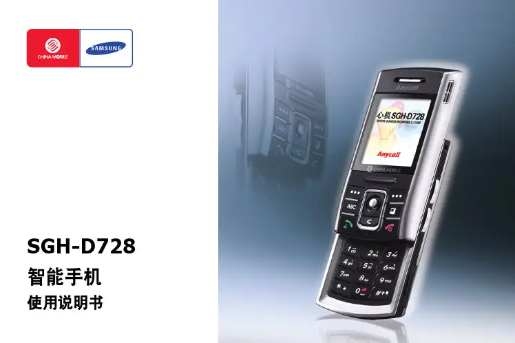
配件介绍 . . . . . . . . . . . . . . . . . . . . . . . . . . . . . . . . . . . . . . . . . . . . . . . . . . . . . . 18 手机部位图 . . . . . . . . . . . . . . . . . . . . . . . . . . . . . . . . . . . . . . . . . . . . . . . . . . . . 19 安装 SIM 卡 . . . . . . . . . . . . . . . . . . . . . . . . . . . . . . . . . . . . . . . . . . . . . . . . . . . . 22 安装电池 . . . . . . . . . . . . . . . . . . . . . . . . . . . . . . . . . . . . . . . . . . . . . . . . . . . . . . 23 电池充电 . . . . . . . . . . . . . . . . . . . . . . . . . . . . . . . . . . . . . . . . . . . . . . . . . . . . . . 24 开机和关机 . . . . . . . . . . . . . . . . . . . . . . . . . . . . . . . . . . . . . . . . . . . . . . . . . . . . 25 使用选配存储卡 . . . . . . . . . . . . . . . . . . . . . . . . . . . . . . . . . . . . . . . . . . . . . . . . . 25
DP782LC1A20282446使用说明书
DP782LC1A20282446使用说明书
第一步:在室内取下电池盖,按一下设定键(p718和dp728的设定键位置一样)。
听到“dingdong”提示音即可进行下一步操作。
(“三星指纹锁设定键在哪里”)。
第二步:走到室外,在屏幕上输入当前开锁密码(初始密码“1234”),再按[*]键确认。
听到提示音
“dingdongdeng,dingding”进行下一步。
第三步:指示灯亮时用将要登记的指纹接触指纹识别器。
听到“叮”的声音,待指示灯灭后收回手指。
(反复识别三次)听到提示音为“dingdongdeng”则说明指纹登记成功。
第四步:如果需要结束登记,请从房门内侧按锁体上的[登记]按键。
听到提示音“dingdongdeng”,那么恭喜您,指纹录入成功了。
dp728指纹锁最有意思的就是它的提示音,因为是进口指纹锁,所以提示音没有具体地说中文,而是用音调代替。
您在设置的时候也应该仔细听提示音,听到提示音正确再进行下一步。
Samsung Electronics 产品说明书
Table of Contents ................................................................................................................................................................... 3 List of Figures .......................................................................................................................................................................... 4 List of Tables ........................................................................................................................................................................... 4 Version History .. (5)Handling Guide ....................................................................................................................................................................... 6 ARTIK 530 Development Board Overview (7)features (7)Block diagram ....................................................................................................................................................................................... 8 Mechanical Drawings ........................................................................................................................................................................... 9 ARTIK 530 Module ................................................................................................................................................................ 11 ARTIK 530 Module Specification ........................................................................................................................................................ 11 ARTIK 530 Development Board Interposer Board .. (12)Interposer Board Boot mode Configuration .................................................................................................................................... 13 USB OTG ............................................................................................................................................................................................... 14 HDMI 1.4a ............................................................................................................................................................................................ 14 LVDS ..................................................................................................................................................................................................... 15 Ethernet................................................................................................................................................................................................ 15 Antenna ................................................................................................................................................................................................ 16 ARTIK 530 Development Board Platform Board .. (17)Configuration of External Power Source .......................................................................................................................................... 18 SD-Card Interface................................................................................................................................................................................ 19 EarJack Interface ................................................................................................................................................................................. 19 MIPI DSI/CSI Interface ......................................................................................................................................................................... 19 USB Host 2.0 Interface ....................................................................................................................................................................... 21 Connector to IF Board Interface ........................................................................................................................................................ 22 ARTIK 530 Development Environment IF Board .............................................................................................................. 23 Preview on the ARTIK IF board .......................................................................................................................................................... 23 Configuration of external Power Source .......................................................................................................................................... 24 ARTIK 530 Development Board Booting (25)Serial Port Connection ....................................................................................................................................................................... 25 Terminal Emulator Installation ......................................................................................................................................................... 26 Power on the ARTIK 530 Development Board.................................................................................................................................. 27 Legal Information .. (29)Figure 1. Preview of the ARTIK 530 Development Board .................................................................................................... 7 Figure 2. ARTIK 530 Development Board .............................................................................................................................. 8 Figure 3. Mechanical Drawing ARTIK 530 Development Board and Interposer Board all dimensions are in [mm] .. 9 Figure 4. Mechanical Drawing ARTIK 530 Development Board Platform Board all dimensions are in [mm] .......... 10 Figure 5. ARTIK 530 Development Board Interposer Board Left Top Side, Right Bottom Side .................................. 12 Figure 6. ARTIK 530 Development Board Booting Switch Location ................................................................................ 13 Figure 7. USB OTG Interface location on the Interposer Board ...................................................................................... 14 Figure 8. HDMI 1.4a Interface location on the Interposer Board ................................................................................... 14 Figure 9. LVDS Interface location on the Interposer Board ............................................................................................. 15 Figure 10. Ethernet Interface location on the Interposer Board .................................................................................... 15 Figure 11. Antenna location on the Interposer Board ..................................................................................................... 16 Figure 12. ARTIK 530 Development Board Platform Board Left Bottom Side, Right Top Side ................................... 17 Figure 13. Jumper Interface locations JP1-JP4 on Connectors J702, J703 of the Platform Board ............................... 18 Figure 14. SD-Card Interface location on the Platform Board ........................................................................................ 19 Figure 15. Ear Jack Interface location on the Platform Board ......................................................................................... 19 Figure 16. MIPI DSI Interface location on the Platform Board ........................................................................................ 20 Figure 17. MIPI CSI Interface Location on the Platform Board ....................................................................................... 20 Figure 18 USB2.0 Interface location on the Platform Board ........................................................................................... 21 Figure 19. Expansion Connector Interface location on the Platform Board ................................................................. 22 Figure 20. ARTIK 530 Development Board IF Board ......................................................................................................... 23 Figure 21. Jumper Interface locations J20, J21 on the IF Board ....................................................................................... 24 Figure 22. Typical Linux® Serial Console ........................................................................................................................... 25 Figure 23. USB Serial Cable hooked up to the Platform Board ....................................................................................... 26 Figure 24 Connection Power adaptor with development Board .................................................................................... 27 Figure 25. Power switch location on the development Board ........................................................................................ 28 Figure 26. Power button location on the development Board (28)Table 1. Main Features of the ARTIK 530 Module ............................................................................................................. 11 Table 2. Boot option that can be set on the Interposer Board ....................................................................................... 13 Table 3 Antenna spec ........................................................................................................................................................... 16 Table 4. Connector J2 ............................................................................................................................................................ 23 Table 5. Connector J3 (24)Precaution against Electrostatic DischargeWhen using the Samsung ARTIK ™ 530 Development Board, ensure that the environment is protected against static electricity: ContaminationDo not use the ARTIK 530 Development Board in an environment exposed to dust or dirt adhesion. Temperature/HumidityThe ARTIK 530 Development Board is sensitive to:1. Environment2. Temperature3. HumidityHigh temperature or humidity deteriorates the characteristics of ARTIK 530 Development Board, therefore, do not store or use the ARTIK 530 Development Board under such conditions. Mechanical ShockDo not to apply excessive mechanical shock or force to the ARTIK 530 Development Board. ChemicalDo not expose the ARTIK 530 Development Board to chemicals. Exposure to chemicals leads to reactions that deteriorate the characteristics of the ARTIK 530 Development Board. EMS (Electro Magnetic Susceptibility)Strong electromagnetic waves or magnetic fields may affect the characteristics of the ARTIK 530 Development Board during the operation under insufficient PCB circuit design for Electro Magnetic Susceptibility (EMS).The ARTIK 530 Development Board consists of one Interposer Board, one Platform Board and one IF Board. The Interposer Board does include the ARTIK 530 Module. The ARTIK 530 Development Board is an affordable approach for developing an IoT solution. Figure 1 shows the form factors of the various boards that make up the ARTIK 530 Development Board.Figure 2 shows the block diagram of the ARTIK 530 Development Board, if you want more information on the ARTIK 530 Module please consult the ARTIK 530 Module Datasheet.Figure 3 and Figure 4 show the ARTIK 530 Development Board Interposer Board and the Platform Board respectively.The ARTIK 530 Development Board contains the ARTIK 530 Module. This section will describe some of the main features of this module. For more information on the ARTIK 530 Module please consult the ARTIK 530 Module datasheet.The ARTIK 530 Module is designed for IoT devices and it contains a lot of functions based on a Linux ®system. Not only multimedia functions but also network functions for example 802.11 or ZigBee ®. In addition the ARTIK 530 Module has mass storage functionality and its own security solution. Table 1 shows the main features of the ARTIK 530 Module that is part of the ARTIK 530 Development Board.®®®®The Interposer Board as depicted in Figure 5 highlights the most important components on the Interposer board.This section describes the various boot modes that are supported on the ARTIK 530 Development Board. Table 2 and Figure 6 show how to manipulate SW402 and where SW402 is located on the Interposer Board to set the various booting options that are available on the ARTIK 530 Development Board.When ‘eMMc 1st Boot’ is selected as a booting option, the system will first try to boot from eMMc, if this fails the system will search for an SD Card to boot from. If booting from the SD-Card also fails the system tries to boot from USB. When choosing the SD-Card booting option, the system starts with booting from SD, and if this fails will continue to try a USB boot. When USB is selected as the booting mechanism of choice, only a USB boot will be attempted.The Interposer board has one USB OTG connector located as can be seen in Figure 7.The Interposer board has one HDMI 1.4a connector (Micro D-Type) located as can be seen in Figure 8. The following video formats are supported:1.480p/************/60Hz,576p/576i@50Hz2.720p/720i @50Hz/59.94Hz/60HzThe Interposer board has one LVDS Interface containing 5x data channels and one clock channel, its location can be seen in Figure 9. The available maximum resolution is 1920x1080@60fps.The Interposer board has one Ethernet Interface, its location can be seen in Figure 10. The Ethernet Interface is based on 802.3az-2010 complying to the Energy Efficient Ethernet (EEE) standard. The maximum theoretical speed of the interface is 1000Mbps.If 802.11 or Bluetooth® functionality is required, the antenna which is enclosed as part of the ARTIK 530 Development Kit has to be attached to the Interposer board as depicted in Figure 11. More details on the antenna spec is given in Table 3.The Platform Board as depicted in Figure 12 highlights the most important components on the Interposer board.Through selection of the Jumpers JP1-JP4, located on J702, J703, the power source can be selected. When power is provided from a DC-5V Adapter or a Battery, all jumpers are in the 1-2 position. When power is provided from the DC-5V Adapter and at the same time a battery is connected that is being charged (Battery Charging Mode), all jumpers are in the 2-3 position. When the jumpers [JP1-JP4] are in the 1-2 position, (DC-5V Adapter mode or Battery mode) either connect a battery or the DC-5V adapter but never both at the same time. When the jumpers [JP1-JP4] are in the 2-3 position, (Battery Charging Mode) connect both a battery and the DC-5V Adapter.Figure 13 shows the default settings and how to switch between the settings. When the ARTIK 530 Development Board is used with an external power adapter make certain that you use a 5V-5A adapter with a 2.1x5.5mm plug.The Platform board has one SD-CARD interface supporting SD3.0 located as can be seen in Figure 14.The Platform board has one 4 pin ear jack interface supporting stereo audio as can be seen in Figure 15.The Platform board has one MIPI DSI and one MIPI CSI interface. The location of the DSI Display interface can be seen in Figure 16. The location of the MIPI CSI interface can be seen in Figure 17.The MIPI DSI interface can operate at a maximumresolution of WUXGA (1920x1200), whereas the MIPI CSI interface can have a static resolution of 5M pixels or a dynamic resolution for video capturing of 1080P.The Platform board has one USB 2.0 Interface. The location of the USB 2.0 interface can be seen in .The Platform board has one expansion connector that can be seen in Figure 19. This connector enables for expansion possibilities.Figure 20 shows the highlights of the connector IF board. In addition Table 4 with J2 and Table 5 with J3 show the pinout of the connectors with its meaning.Through selection of the Jumpers J20 and J21 you can choose the IO power source (I 2C, UART GPIO) or the XGPIO power source of either, 1.8V, 3.3V or 5V. Figure 21 shows how to set the various jumpers to switch between power sources.This section will describe how to start working with your ARTIK 530 Development Environment by setting up a serial connection on your development PC and booting up the ARTIK 530 Development Environment.As a first step we will select a serial console to communicate with the ARTIK 530 Module that is located on the ARTIK 530Development Environment. You can use a typical Linux ®serial console as depicted in Figure 22, using the serial connector. If your PC does not have a serial port, use the micro-USB B serial cable instead. To use the serial USB cable you need to install the associated device driver. Figure 23 depicts the USB serial cable and where it is hooked up to the Platform Board.Setting up a connection with the ARTIK 530 Module can be done in a wired or wireless manner. Here we choose to install PuTTY a free serial console. The software can be downloaded from /. Once downloaded go through the following steps:1.Open the device manager on the control panel.2.When using a PC install the USB to Serial driver. The driver can be found at the following location:(/Drivers/CDM/CDM21218_Setup.zip). For other drivers please visit(/Drivers/D2XX.htm).3.Check the COM port number on your PC when you connect the USB serial cable. In our case the COM port allocated4.a.Set the “Serial line” as the COM port number found in step 3.b.Set the COM speed to "115200".c.Set the connection type to "Serial".d.Save the session under ARTIK-Pro.5.Select your saved session and click th e “Open” button.To power up the ARTIK 530 Development Environment you first have to connect the power adapter and the Platform Board as shown in Figure 24. In addition make certain that the jumpers JP1-JP4 located on the Platform Board are set in state 1-2 see Configuration of External Power Source section for details.Turn on the power switch as shown in Figure 25.Once the power switch is turned on, push the power button (SW2), as depicted in Figure 26, for about 1 second. Once released the booting process will start and you should see booting messages from your console, using the serial connection that you previously established.INFORMATION IN THIS DOCUMENT IS PROVIDED IN CONNECTION WITH THE SAMSUNG ARTIK ™ DEVELOPMENT BOARD AND ALL RELATED PRODUCTS, UPDATES, AND DOCUMENTATION (HEREINAFTER “SAMSUNG PRODUCTS”). NO LICENSE, EXPRESS OR IMPLIED, BY ESTOPPEL OR OTHERWISE, TO ANY INTELLECTUAL PROPERTY RIGHTS IS GRANTED BY THIS DOCUMENT. THE LICENSE AND OTHER TERMS AND CONDITIONS RELATED TO YOUR USE OF THE SAMSUNG PRODUCTS ARE GOVERNED EXCLUSIVELY BY THE SAMSUNG ARTIK ™ DEVELOPER LICENSE AGREEMENT THAT YOU AGREED TO WHEN YOU REGISTERED AS A DEVELOPER TO RECEIVE THE SAMSUNG PRODUCTS. EXCEPT AS PROVIDED IN THE SAMSUNG ARTIK ™ DEVELOPER L ICENSE AGREEMENT, SAMSUNG ELECTRONICS CO., LTD. AND ITS AFFILIATES (COLLECTIVELY, “SAMSUNG”) ASSUMES NO LIABILITY WHATSOEVER, INCLUDING WITHOUT LIMITATION CONSEQUENTIAL OR INCIDENTAL DAMAGES, AND SAMSUNG DISCLAIMS ANY EXPRESS OR IMPLIED WARRANTY, ARISING OUT OF OR RELATED TO YOUR SALE, APPLICATION AND/OR USE OF SAMSUNG PRODUCTS INCLUDING LIABILITY OR WARRANTIES RELATED TO FITNESS FOR A PARTICULAR PURPOSE, MERCHANTABILITY, OR INFRINGEMENT OF ANY PATENT, COPYRIGHT, OR OTHER INTELLECTUAL PROPERTY RIGHT.SAMSUNG RESERVES THE RIGHT TO CHANGE PRODUCTS, INFORMATION, DOCUMENTATION AND SPECIFICATIONS WITHOUT NOTICE. THIS INCLUDES MAKING CHANGES TO THIS DOCUMENTATION AT ANY TIME WITHOUT PRIOR NOTICE. THIS DOCUMENTATION IS PROVIDED FOR REFERENCE PURPOSES ONLY, AND ALL INFORMATION DISCUSSED HEREIN IS PROVIDED ON AN “AS IS” BASIS, WITHOUT WARRANTIES OF ANY KIND. SAMSUNG ASSUMES NO RESPONSIBILITY FOR POSSIBLE ERRORS OR OMISSIONS, OR FOR ANY CONSEQUENCES FROM THE USE OF THE DOCUMENTATION CONTAINED HEREIN.Samsung Products are not intended for use in medical, life support, critical care, safety equipment, or similar applications where product failure could result in loss of life or personal or physical harm, or any military or defense application, or any governmental procurement to which special terms or provisions may apply.This document and all information discussed herein remain the sole and exclusive property of Samsung. All brand names, trademarks and registered trademarks belong to their respective owners. For updates or additional information about Samsung ARTIK™, contact the Samsung A RTIK ™ team via the Samsung ARTIK™ website at www.artik.io .Copyright © 2017 Samsung Electronics Co., Ltd.All rights reserved. No part of this publication may be reproduced, stored in a retrieval system, or transmitted in any form or by any means, electric or mechanical, by photocopying, recording, or otherwise, without the prior written consent of Samsung Electronics.。
三星 SyncMaster 788DF 说明书
z 显示器可能会发生故障,导致电击或失火。
在暴风雨或雷电期间,或者要有相当长一段时间不用时,请把插头从插座上拔 下。
z 如果不这样做,有可能造成电击或起火。
不要试图用拉电线或信号电缆的办法来移动显示器。 z 这样由于会损坏电缆而造成破坏、电击或起火。
不要直接往显示器上喷洗涤剂。
使用我们推荐的洗涤剂,并用光滑的布。 z 这样你可以避免镀膜的显像管受到损伤,或者显示器机箱表面的漆溶化, 机箱开裂或褪色。 z 你可以在任何一家三星服务中心买到我们推荐的洗涤剂。
如果插头和插脚之间的接头有灰尘或脏了,用一块干布好好地擦干净。 z 脏的接头会造成电击或火灾。
清洁
在清洁显示器的机箱或显像管的表面时,要用一块稍稍润湿了的软纤维布来擦 拭。 不要用水来清洁显示器。要用水稀释了的柔和的洗涤剂。 (有些洗涤剂包含大量基于酒精的溶剂,这会损坏(颜色改变)显示器机箱或使它 开裂。 显像管上的防眩光/抗静电的表面镀膜也会受到影响。) 使用前先用水稀释洗涤剂 (1:10的比例)。
“进入”按钮。 [ ]
电源按钮[ ]
电源指示灯
打开 OSD 菜单。也用于退出 OSD 菜单或回到上一菜单。
这些按钮让你选择突出并调整菜单里的一些项目。 用于选择 OSD 菜单 使用这个按钮来打开或关闭显示器。 表示正常模式或节电模式。
有关节电功能的进一步信息请看手册里说明的节电器。为了节省能源,在不需要它,或长时 间不去看它的时候,请把你的显示器关掉。
不要使用损坏了的或松动了的插头。
z 这会引起电击或起火
不要去拉电线来试图拔出插头,也不要用湿手去触摸插头。 z 这会引起电击或起火。
三星洗衣机操作说明书
不要将汽油、石油、酒精等可燃液体放在洗 衣机内或者放在洗衣机的附近。另外请不要 把沾有这些液体的衣物放进 洗衣机里。
可能导致爆炸、火灾 等危险。 不要直接使用干洗剂, 也不要将沾有干洗剂 的衣服直接洗涤或 者脱水。
3
4
使用时
禁止小孩在洗衣机上玩耍,也应避免小孩 进入洗衣机内筒里。
产品执行标准:
GB4706.1 GB4706.20 GB4288 GB19606
GB4706.24 GB4706.26 GB4343.1 GB17625.1
DC68-01997H
WD-B1265R WD-B1265D WD-B1265C WD-B1065C
序 言
1
※ 欢迎选购三星滚筒洗衣机。产品使用说明书中包括有关安 装、使用及维护本机的重要信息,请妥善保管说明书及仔细 阅读这些说明内容,以便能够充分利用洗衣机的功能并且延 长本机的使用寿命。
在使用洗衣机之前请阅读以下内容
·本洗衣机仅为家庭使用设计。 ·包装材料可能对儿童有危险,请把所有包装材料(如塑料袋等)置于儿童不能触及之处。
·洗衣机安装在干燥和通风的室内。洗衣机长期在潮湿的地方使用时,空气中的多种细菌粘 到洗衣机上会产生变黑,发霉现象,给人体健康带来危害。
·请确保水和电均由合格的专业人员连接,注意阅读本用户手册的说明和当地的安全规则。 ·在使用前,所有的包装和包装螺栓必须拆除掉,否则洗衣机在运行后会产生过大的振动和
可能导致烧伤、损坏等危险。
在安装时必须要注意以下事项
安
��
全
注
电源及安装时
意
事
请安装在地面平坦、坚固的地方。
洗涤中,不要将带磁性的物品放在洗衣机顶
三星 SGH-E888 手机 说明书
干扰
移动通信可能会受到无线电干扰。无线电干扰会影响手机 的性能。
遵守特殊规定
在任何地方都要遵守特殊规定。在禁止使用手机或可能产 生干扰或危险时,必须关闭手机。
防水 此手机不能够防水,请保持其干燥。
合理使用
6
闪光灯 照相机 照相机镜头 转换开关
音量键 软键 (左)
拨号键
数字字母键
话筒
听筒
显示屏
导航键 (上 / 下 / 左 / 右) 软键 (右) 电源开 / 关 / 功能表退出键 WAP浏览/ 确认键 修改键
特殊功能键
耳机插孔 照相机键
开始使用
开始使用
使用手机的初始步骤
SIM卡信息 当您申请入网时,您就会得到一张插入式SIM卡,其中载 有您的专用信息,例如PIN码及可以获得的服务选项等。
5
配件介绍
您可以拥有下列配件
您的手机
手机部位图
手机
旅行充电器
电池
使用说明书
可向当地的三星经销商购得各种附件。
• 随手机提供的配件和三星经销商出售的 附件可能依据国家地区的不同而不同。
• 购买的附件 (电池,充电器等)仅能 用于三星指定的产品。
• 购买的附件 (电池,充电器等)用在 其它三星未指定的产品上而出现问题 时,即使在保修期内也不会给予保修。
(在手机右侧面)
9
开始使用
开始使用
显示屏 部位图
图标*
10
图标区 显示各图标。
文本和图形区 显示信息、指令和任何您 输入的信息。
软键指示区 显示当前分配给两个软键的 功能。
三星D788中文说明书
网址中国印刷编码:GH68-18916A 中文 08/2009 版本 1.3SGH-D788使用说明书使用本说明书本使用说明书专门用于指导您使用手机的功能。
如欲迅速使用手机,请参照“手机简介”、“手机的安装和准备”以及“使用基本功能”。
指示图标在开始使用前,请熟悉一下本说明书中的图标:警告—可能伤及自己或他人。
小心—可能损坏手机或其它设备。
注意—注释、使用提示或附加信息。
X参照—具有相关信息的页面。
例如:X12(表示“见12页”)。
ii使用本说明书iii版权信息本手机所采用的技术和产品的权利归各自的所有人所有:•Bluetooth ®是全球各地Bluetooth SIG 公司的注册商标—蓝牙 QD ID:B014287。
•JAVA™ 是Sun Microsystems 公司的商标。
•Windows Media Player ® 是微软公司的注册商标。
→下一步—为执行步骤必须选择的选项或功能表的次序。
例如:按下<功能表>→信息→发信息(表示功能表,下一步信息,下一步发信息)。
[]方括号—手机按键。
例如:[](表示电源开/关/功能表退出键)。
<>尖括号—在各屏幕上控制不同功能的软键。
例如:< 确认> (表示确认软键)。
iv目录安全和使用信息 2安全警告 .......................................2安全注意事项 ..................................4重要使用信息 . (6)手机简介 9配件介绍 .......................................9手机部位图 ..................................10按键 ...........................................11显示 ...........................................12图标 . (13)手机的安装和准备 15安装SIM 卡和电池 .........................15电池充电 .....................................17插入存储卡(选配) .. (18)使用基本功能 19开机和关机 (19)目录v使用功能表 ...................................20根据需要设定手机 ...........................21使用基本通话功能 ...........................22发送和查看信息 ..............................24添加和查找联系人 ...........................27使用照相机基本功能 ........................28收听音乐 ......................................29浏览WAP . (31)使用高级功能 32使用高级通话功能 ...........................32使用高级电话簿功能 ........................34使用高级信息功能 ...........................35使用高级音乐功能 (36)使用工具和应用程序 38使用蓝牙无线功能 ...........................38打印图片 ......................................39编写和发送SOS 信息 . (40)录制和播放语音备忘录 ......................41使用JAVA 游戏和应用程序 ................42编辑图片 ......................................43创建和查看世界时间 ........................45设定和使用闹钟 ..............................46使用计算器 ...................................47货币或长度等基本换算 ......................47设定倒计时定时器 ...........................47使用秒表 ......................................47编写文字备忘录 ..............................48管理日历 .. (48)故障排除 a安全和使用信息遵守下列注意事项,以免出现危险或非法情况,并确保手机性能最佳。