Fluke15B万用表校准说明
福禄克 15B Max 17B 校准手册 说明书

15B MAX/17B MAXDigital MultimetersCalibration ManualAugust 2022©2022 Fluke Corporation. All rights reserved.Specifications are subject to change without notice.All product names are trademarks of their respective companies.LIMITED WARRANTY AND LIMITATION OF LIABILITYEach Fluke product is warranted to be free from defects in material and workmanship under normal use and service. The warranty period is 1 year and begins on the date of shipment. Parts, product repairs, and services are warranted for 90 days. This warranty extends only to the original buyer or end-user customer of a Fluke authorized reseller, and does not apply to fuses, disposable batteries, or to any product which, in Fluke's opinion, has been misused, altered, neglected, contaminated, or damaged by accident or abnormal conditions of operation or handling. Fluke warrants that software will operate substantially in accordance with its functional specifications for 90 days and that it has been properly recorded on non-defective media. Fluke does not warrant that software will be error free or operate without interruption.Fluke authorized resellers shall extend this warranty on new and unused products to end-user customers only but have no authority to extend a greater or different warranty on behalf of Fluke. Warranty support is available only if product is purchased through a Fluke authorized sales outlet or Buyer has paid the applicable international price. Fluke reserves the right to invoice Buyer for importation costs of repair/replacement parts when product purchased in one country is submitted for repair in another country.Fluke's warranty obligation is limited, at Fluke's option, to refund of the purchase price, free of charge repair, or replacement of a defective product which is returned to a Fluke authorized service center within the warranty period.To obtain warranty service, contact your nearest Fluke authorized service center to obtain returnauthorization information, then send the product to that service center, with a description of the difficulty, postage and insurance prepaid (FOB Destination). Fluke assumes no risk for damage in transit. Following warranty repair, the product will be returned to Buyer, transportation prepaid (FOB Destination). If Fluke determines that failure was caused by neglect, misuse, contamination, alteration, accident, or abnormal condition of operation or handling, including overvoltage failures caused by use outside the product’s specified rating, or normal wear and tear of mechanical components, Fluke will provide an estimate of repair costs and obtain authorization before commencing the work. Following repair, the product will be returned to the Buyer transportation prepaid and the Buyer will be billed for the repair and return transportation charges (FOB Shipping Point).THIS WARRANTY IS BUYER'S SOLE AND EXCLUSIVE REMEDY AND IS IN LIEU OF ALL OTHERWARRANTIES, EXPRESS OR IMPLIED, INCLUDING BUT NOT LIMITED TO ANY IMPLIED WARRANTY OF MERCHANTABILITY OR FITNESS FOR A PARTICULAR PURPOSE. FLUKE SHALL NOT BE LIABLE FOR ANY SPECIAL, INDIRECT, INCIDENTAL OR CONSEQUENTIAL DAMAGES OR LOSSES, INCLUDING LOSS OF DATA, ARISING FROM ANY CAUSE OR THEORY.Since some countries or states do not allow limitation of the term of an implied warranty, or exclusion or limitation of incidental or consequential damages, the limitations and exclusions of this warranty may not apply to every buyer. If any provision of this Warranty is held invalid or unenforceable by a court or other decision-maker of competent jurisdiction, such holding will not affect the validity or enforceability of any other provision.11/99Fluke Corporation P.O. Box 9090Everett, WA 98206-9090U.S.A.Fluke Europe B.V.P.O. Box 11865602 BD Eindhoven The NetherlandsTable of ContentsIntroduction (1)Contact Fluke (1)Safety Information (1)Specifications (1)Maintenance (1)General Maintenance (2)Test Fuses (2)Replace Batteries and Fuses (4)Performance Tests (4)Adjustment Procedures (7)i15B MAX/17B MAXCalibration Manualii1IntroductionThe 15B MAX/17B MAX Digital Multimeters (the Product) are 6000 count instruments. The Product is battery powered with a digital display. Unless otherwise identified, all illustrations show the 17B MAX. See the Users Manual for usage information and user-replaceable parts.Contact FlukeFluke Corporation operates worldwide. For local contact information, go to our website: .T o register your product, or to view, print, or download the latest manual or manual supplement, go to our website.+1-425-446-5500 ********************Safety InformationGeneral Safety Information and Symbols are in the printed Safety Information document that ships with the Product and is available at . More specific safety information is listed in this manual where applicable.A Warning identifies hazardous conditions and procedures that are dangerous to the user. A Caution identifies conditions and procedures that can cause damage to the Product or the equipment under test.SpecificationsSafety Specifications are in the Safety Specifications section of the Safety Information document. Complete Product specifications are in the Users Manual and at .MaintenanceBeyond battery and fuse replacement, do not attempt to repair or service the Product unless you are qualified to do so and have the relevant calibration, performance test, and service instructions. The recommended calibration adjustment cycle is 12months.Fluke Corporation P.O. Box 9090Everett WA 98206-9090U.S.A.Fluke Europe B.V.P.O. Box 11865602 BD Eindhoven The Netherlands15B MAX/17B MAX Calibration Manual2XW WarningTo prevent possible electrical shock, fire, or personal injury, and for safe operation and maintenance of the product, see Safety Information.T1.2.3.T o test1.2.●●●●Digital MultimetersMaintenance3XSemiconductors and integrated circuits can be damaged by electrostatic discharge during handling. This notice explains how to minimize damage to these components.1.Understand the problem.2.Learn the guidelines for proper handling.3.Use the proper procedures, packaging, and bench techniques.Follow these practices to minimize damage to static sensitive parts.XW WarningTo prevent electric shock or personal injury. De-energize the product and all active circuits before opening a product enclosure, touching or handling any PCBs or components .•Minimize handling.•Handle static-sensitive parts by non-conductive edges.•Do not slide static-sensitive components over any surface.•When removing plug-in assemblies, handle only by non-conductive edges. •Never touch open-edge connectors except at a static-free work station.•Keep parts in the original containers until ready for use.•Use static shielding containers for handling and transport.•Avoid plastic, vinyl, and Styrofoam ® in the work area.•Handle static-sensitive parts only at a static-free work station.•Put shorting strips on the edge of the connector to help protect installed static-sensitive parts.•Use anti-static type solder extraction tools only.•Use grounded-tipsoldering irons only.15B MAX/17B MAX Calibration Manual4Replace Batteries and FusesXW WarningTo prevent false readings, which could lead to possible electric shock or personal injury, replace the batteries as soon as the battery indicator (P) appears.To prevent damage or injury, install ONL Y replacement fuses with the specifiedamperage, voltage, and interrupt ratings.Disconnect test leads before you open the case or the battery door.Dispose of old devices in a professional and environmentally appropriate manner.●Delete personal data on the Product before disposal.●Remove batteries that are not integrated into the electrical system before disposal.Dispose of batteries separately.T o replace the batteries or fuses, see Figure2.Figure 2. Replace Batteries and FusesPerformance TestsUse the performance tests to make sure the Device Under T est (DUT) operates properly and to make sure the DUT is accurate. If the DUT fails any part of the performance test, repair and/or calibration adjustment are required. See Temperature Connections. If the DUT continues to fail to meet the range indicated, see Contact Fluke.Digital Multimeters Performance T ests5Table 1 lists the equipment required for the performance tests.Before you do the performance test, make sure to warm up the calibrator.T o test each function and operating ranges:1.For each step in Table 2, set the DUT to the specified function and range.2.Connect the source to the input jacks on the DUT.3.Apply the output from the source. For temperature connections, see Figure 3.4.Make sure the DUT readings are within the limits in Table 2.Table 1. Required EquipmentEquipmentRecommended ModelCalibratorFluke Calibration 5502A, 5502E, or 5522A Type K to dual banana adapterFluke 80AK-ATable 2. Performance Specifications Step FunctionCalibrator Output15BMAX 17B MAX Lower Limit Upper Limit Value Frequency or Amplitude 1VAC 5.5 V 50 Hz √√ 5.442 5.558255 V 50 Hz √√54.4255.58355 V 500 Hz √√54.4255.584550 V 50 Hz √√544.2555.851000 V 50 Hz √√98610146VAC/Freq.45 Hz1 VX √44.9245.0875 kHz 1 VX √ 4.992 5.0088100 kHz 3 V X √99.6100.49VAC/Duty50 Hz 3 V (SquareWave)X √49.550.510VDC 5.5 V 0 Hz √√ 5.470 5.5311155 V 0 Hz √√54.7055.3112550 V 0 Hz √√547.0353.113-1000 V 0 Hz √√-1008-99214mVDC 550 mV 0 Hz √√543.5556.515mVAC 550 mV500 Hz√√533.2566.815B MAX/17B MAX Calibration Manual6Step FunctionCalibrator Output15BMAX17BMAXLowerLimitUpperLimitValue Frequency orAmplitude16OHM0 ΩΩ√√-0.30.3 17350 ΩΩ√√348.0352.0 18 3.5 kΩΩ√√ 3.480 3.520 1935 kΩΩ√√34.8035.20 20350 kΩΩ√√348.0352.0 21 3.5 MΩΩ√√ 3.480 3.520 2210 MΩΩ√√9.8210.18 23BEEPER ON40 ΩΩ√√X X24DIODE0.7 V0 Hz√√0.6220.778 25CAP35 nFΩ√√34.2435.76 26350 nFΩ√√342.4357.6 27 3.5 μFΩ√√ 3.320 3.680 2835 μFΩ√√33.2036.80 29350 μFΩ√√332.0368.0 30ADC3.5 A0 Hz√√ 3.444 3.556 31-10 A0 Hz√√-10.18-9.82 32AAC3.5 A50 Hz√√ 3.444 3.556 3310 A400 Hz√√9.8210.18 34mADC35 mA0 Hz√√34.4435.56 35-350 mA0 Hz√√-355.6-344.4 36mAAC35 mA400 Hz√√34.4435.56 37350 mA50 Hz√√344.4355.6 38μADC350 μA0Hz√√344.4355.6 39-3500 μA0Hz√√-3556-3444 40μAAC350 μA40 Hz√√344.4355.6 413500 μA400 Hz√√34443556 42Temp-50 °C X X√-56.4-43.6 4335 °C X X√33.037.0 44400 °C X X√391.0409.0Table 2. Performance Specifications (cont.)Figure 3. Temperature ConnectionsAdjustment ProceduresTable 3 lists the equipment required to adjust the Product.T o enter adjustment mode:1.Remove the battery door and batteries. See Figure2.2.Remove the calibration sticker. See Figure 4.Table 3. Required Equipment for AdjustmentEquipmentRequired CharacteristicsRecommended Model Calibrator-Fluke 5522APotentiometer (17B MAX)Adjust Manually Type K to dual banana (m) adapter-Fluke 80AK-A4.T o put the DUT in adjustment mode, use a small probe to push the calibration button(CAL1). See Figure 6.Figure 6. Adjustment5.Enter the adjustment values on the calibrator.6.For each function, wait 4 seconds for the measurement to stabilize. Then push H toconfirm and go to the next step. The display shows the function and the high voltage indicator, see Table 4.7.For 17B MAX temperature adjustment:e an adjustable potentiometer to make a manual adjustment. See Figure 7.b.Adjust to 0.1 ÁC to 0.3 ÁC at 0 ÁC input.Table 4. Display IndicatorsA High voltage alert BFunctionCAL1WP6HOLD1WP7WP8WP9CAL1128.When you complete adjustment, turn off the DUT.。
01.FLUKE 15B+数字万用表使用介绍
2021/7/1
18
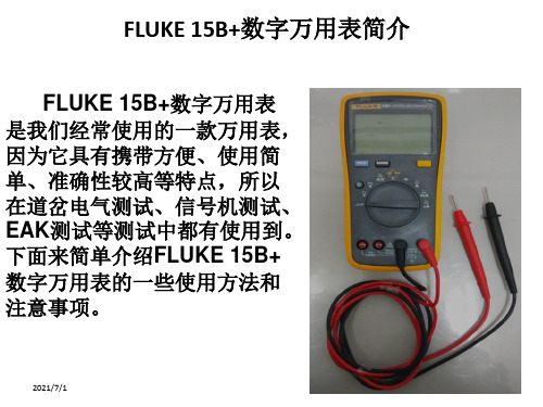
FLUKE 15B+数字万用表的使用
测试电容:
1. 连接测试表笔:我们将黑 表笔接在公共测试插孔, 红表笔接在电容测试插孔 (如右图所示);
2. 选择测试档位:将旋转开 关调至电容测试档位(如 右图所示);
下面的测试步骤方法与其它 测试类似,不在一一赘述。
电容测试档位 红黑表笔的接法
2021/7/1
公共测试插孔:用于所 有的测试,需接黑表笔
用于测量交直流电压、 电阻、二极管、电容 的插孔,需接红表笔
3
FLUKE 15B+数字万用表的显示屏显示内容介绍
未说明的标示是其它型号使用的
蜂鸣档显示
截屏显示
电阻和电阻单位
二极管档位显示 电容和电容单位
高压危险 测试数值显示
2021/7/1
2021/7/1
19
FLUKE 15B+数字万用表的使用注意事项
2021/7/1
20
FLUKE 15B+数字万用表的使用注意事项
2021/7/1
21
国际电气符号表
2021/7/1
22
结束语
若有不当之处,请指正,谢谢!
三个电流测 试档位
电流测试与其它的测试大同小异, 但有以下几点要注意:
1. 电流测试档位有A、mA、µA三 种,分别测试不同的大小的电 流,交直流通过切换键切换
2. A档用一个插孔,mA和µA档用 另外一个插孔
3. A档只能测试10A以下的电流, mA档只能测试400mA以下的电 流
两个电流测 试插孔
蜂鸣档 二极管档 电阻档
2021/7/1
14
FLUKE 15B+数字万用表的使用
fluke万用表使用说明书
fluke万用表使用说明书中FLUKE 15B型和FLUKE 17B可以测量电压、电阻、电流、二极管、三极管、MOS场效应管的测量等几大功能综合在一起的强大的一款小仪器。
为了让你更好的掌握万用表测量方法,电工之家来详解一下它的使用方法和功能与注意事项。
一、测量电压时测量直流电压时,如电池、随身听电源等。
首先将黑表笔插进相印的孔,把旋钮选到相印位置。
二、测量交流电压的时表笔插孔与直流电压的测量一样,不过应该将旋钮打到交流档处所需的量程即可。
交流电压无正负之分,测量方法跟前面相同。
无论测交流还是直流电压,要注意自身安全,不要随便用手触摸表笔的金属部分。
三、测量电流时测量直流电流时。
将黑表笔插入对应孔。
将FLUKE 15B型和FLUKE 17B万用表串进电路中,保持稳定,即可读数。
四、测量电阻时用表笔接在电阻两端金属部位,测量中可以用手接触电阻,但不要把手同时接触电阻两端,这样会影响测量精确度,因为人体是电阻很大。
五、测量二极管时表笔位置与电压测量一样;用红表笔接二极管的正极,黑表笔接负极,这时会显示二极管OL。
再次对调表笔会显示一个数值。
再次调换表笔,显示屏显示“OL.”则为正常。
因为二极管的反向电阻很大,否则此管已被击穿或性能已经改变。
六、三极管的测量表笔插位同上;其原理同二极管。
先假定A脚为基极,用黑表笔与该脚相接,红表笔与其他两脚分别接触其他两脚;然后再用红笔接A脚,黑笔接触其他两脚,且此管为PNP管。
那么集电极和发射极如何判断呢?数字表不能像指针表那样利用指针摆幅来判断。
七、MOS场效应管的测量利用FLUKE 15B型和FLUKE 17B的二极管档。
若某脚与其他两脚间的正反压降均大于2V,即显示“1”,此脚即为栅极G。
再交换表笔测量其余两脚,压降小的那次中,黑表笔接的是D极(漏极),红表笔接的是S极(源极)。
在使用FLUKE 15B型和FLUKE 17B 的同时也要注意以下问题避免可能受到电击或人员伤害,以及避免对电表或待测装置造成损害,请遵照下面的惯例说明使用电表:①进行连接时,先连接公共测试导线,再连接带电的测试导线;切断连接时,则先断开带电的测试导线,再断开公共测试导线。
福禄克15B万用表使用说明知识分享

福禄克15B万用表使用说明福禄克15B数字万用表使用方法简介:福禄克15 B数字万用表属于比较简单的测量仪器。
本篇,教大家数字万用表的正确使用方法。
从数字万用表的电压、电阻、电流、二极管、三极管、MOS场效应管的测量等测量方法开始,让你更好的掌握万用表测量方法。
一、电压的测量1、直流电压的测量,如电池、随身听电源等。
首先将黑表笔插进“com”孔,红表笔插进“V Ω► ( 把旋钮选到此位置如图:直流选择档位(注意:“V-”表示直流电压档,“V~”表示交流电压档,“A”是电流档),接着把表笔接电源或电池两端;保持接触稳定。
数值可以直接从显示屏上读取,若显示为“OL”,则表明量程太小,那么就要加大量程后再测量工业电器。
如果在数值左边出现“-”,则表明表笔极性与实际电源极性相反,此时红表笔接的是负极。
2、交流电压的测量:交流选择档位表笔插孔与直流电压的测量一样,不过应该将旋钮打到交流档“V~”处所需的量程即可。
交流电压无正负之分,测量方法跟前面相同。
无论测交流还是直流电压,都要注意人身安全,不要随便用手触摸表笔的金属部分。
二、电流的测量电流选择档位按此键转换交流直1、直流电流的测量。
先将黑表笔插入“COM”孔。
若测量大于400mA的电流,则要将红表笔插入“10A”插孔并将旋钮打到直流“10A”档;若测量小于400mA的电流,则将红表笔插入“400mA”插孔,将旋钮打到直流400mA以内的合适量程。
调整好后,就可以测量了。
将万用表串进电路中,保持稳定,即可读数。
若显示为“OL.”,那么就要加大量程;如果在数值左边出现“-”,则表明电流从黑表笔流进万用表。
交流电流的测量。
测量方法与1相同,不过应选择交流模式,电流测量完毕后应将红笔插回“”孔,若忘记这一步而直接测电压,哈哈!你的表或电源会在“一缕青烟中上云霄”--报废!三、电阻的测量:按此键转换二极将表笔插进“COM”和”孔中,把旋钮打旋到“Ω”中所需的量程,用表笔接在电阻两端金属部位,测量中可以用手接触电阻,但不要把手同时接触电阻两端,这样会影响测量精确度的--人体是电阻很大但是有限大的导体。
fluke中文使用手册15B-17B

页码
1 1 1 5 5 5 6 6 6 6 6 6 7 8 8 9 9 9
i
15B & 17B
用户手册
测量频率和占空比(仅限 17B) ................................................................................ 维护................................................................................................................................ 一般维护.................................................................................................................... 测试保险丝 ................................................................................................................ 更换电池和保险丝 ..................................................................................................... 维修和零件 ..................................................................................................................... 通用技术指标 ................................................................................................................. 准确度指标 ..................................................................................................................... 10 10 10 11 11 11 12 14
Fluke15B万用表校准说明

设置校准仪为待机状态
4
电容校准
R11
350nF
349.0to351.0nF
339.2到360.8mVac
设置5520A为待机状态
8
直流电压
N/A
3.5Vdc
3.480到3.520Vdc
9
35Vdc
34.80到35.20Vdc
10
350Vdc
348.0到352.0Vdc
11
-1000Vdc
-992到-1008Vdc
12
直流电压
mV
N/A
0.35Vdc
345.5到354.5mVdc
11?
14
3.5k?
3.480到3.520k?
15
35k?
34.80到35.20k?
16
0.35M?
348.0到352.0k?
17
3.5M?
3.480到3.520M?
18
35M?
34.45到35.55M?
19
二极管
○(一次)
0.7Vdc
iconON
0.630到0.770Vdc
15B功能测试
步骤
测试功能
开关位置
按钮
5520A输出
读数范围
1
交流电压
N/A
3.5V50Hz
3.462到3.538Vac
2
35V500Hz
34.62到35.38Vac
3
350V50Hz
346.2到353.8Vac
4
5
1000V50Hz
Au到RangeiconOFFOL.
FLUKE 15B 17B 说明书

安全工作规范
回顾安全信息,并遵守第 2 和第 3 页的安全工作规范。
1
15B & 17B
用户手册
XW警告及预防方法 为避免可能受到电击或人员伤害,以及避免对电表或待测装置造成损害,请遵照下面的规范说明使用电表:
在使用电表前,请检查机壳。切勿使用已损坏的电表。检查是否有裂纹或缺少塑胶件。特别注意接头周围的绝缘。 检查测试表笔的绝缘是否损坏或表笔金属是否裸露在外。检查测试表笔是否导通。请在使用电表之前更换已被损坏的测试表笔。 用电表测量已知的电压,确定电表操作正常。请勿使用工作异常的电表。仪表的保护措施可能已经失效。若有疑问,应将仪表送 修。 请勿在连接端子之间或任何端子和地之间施加高于仪表额定值的电压。 对 30 V 交流(有效值),42 V 交流(峰值)或 60 V 直流以上的电压,应格外小心,这些电压有电击危险。 测量时请选择合适的接线端子、功能和量程。 请勿在有爆炸性气体、蒸气或粉尘环境中使用电表。 使用测试探针时,手指应保持在保护装置的后面。 进行连接时,先连接公共测试表笔,再连接带电的测试表笔;切断连接时,则先断开带电的测试表笔,再断开公共测试表笔。 测试电阻、通断性、二极管或电容器之前,应先切断电路的电源并把所有高压电容器放电。 若未按照手册的指示使用电表,电表提供的安全功能可能会失效。 对于所有功能,包括手动或自动量程,为了避免因读数不当导致电击风险,首先使用交流功能来验证是否有交流电压存在。然 后,选择等于或大于交流量程的直流电压。
安全须知
Fluke Model 15B 和 17B 符合 IEC 1010-1 CAT I 1000 V、CAT II 600 V 和 CAT III 300 V 过压标准。请参 阅“规格”。 必须按照本手册的规定使用电表,否则电表所提供的保护 可能会无效。 本手册内,警告一词代表对使用者构成危险的情况或行 为。 注意一词代表对电表或被测试设备可能造成损坏的情况或 行为。 有关电表和手册所用的国际符号,请参阅表 1 的解释。
Fluke15B万用表校准说明 (2)

直流电压
N/A
V dc
到V dc
9
35 V dc
到V dc
10
350 V dc
到V dc
11
-1000 V dc
-992到-1008 V dc
12
直流电压
mV
N/A
V dc
到dc
13
电阻
N/A
350
到
14
k
到k
15
35 k
到k
16
M
到k
17
M
到M
18
35 M
到M
19
二极管
○(一次)
V dc
icon ON
设置校准仪为待50 nF
to nF
到V dc
20
通断
○(再按一次)
40
Icon ON
Beeper ON
21
-
-
800
Beeper OFF
功能测试合格,不需要校准。
15B校准
步骤
测试功能
开关位置
电位器
5520
读数范围
1
直流电压mV
校准
R18
350mV dc
to mV dc
对于步骤2,如果显示读数在到V dc之间,不需要校准
2
直流电压校准
15B功能测试
步骤
测试功能
开关位置
按钮
5520A输出
读数范围
1
交流电压
N/A
V 50 Hz
到V ac
2
35 V 500 Hz
到V ac
3
350 V 50 Hz
到V ac
4
- 1、下载文档前请自行甄别文档内容的完整性,平台不提供额外的编辑、内容补充、找答案等附加服务。
- 2、"仅部分预览"的文档,不可在线预览部分如存在完整性等问题,可反馈申请退款(可完整预览的文档不适用该条件!)。
- 3、如文档侵犯您的权益,请联系客服反馈,我们会尽快为您处理(人工客服工作时间:9:00-18:30)。
15B功能测试
功能测试合格,不需要校准。
15B 校准
步骤
测试功能 开关位置
电位器 5520 读数范围
1 直流电压mV
校准
R18
350mVdc
对于步骤2,如果显示读数在到之间,不需要校准
2 直流电压校准 R18
35Vdc
如果显示读数少于,调节
R18使显示读数在到之间。
如果显示读数超过调节R18使显示读数在到之间。
3 交流电压校准 R8
35V50Hz
如果步骤2的直流电压标定少于35Vdc ;调节R8使显示读数在到之间。
如果步骤2的直流电压标定等于或大于35Vdc ;调节R8使显示读数在到之间。
设置校准仪为待机状态
4 电容校准 R11 350nF
9 35Vdc 到 10 350Vdc 到
11 -1000Vdc
-992到-1008Vdc 12 直流电压 mV
N/A
到 13 电阻
N/A
350
到 14
到 15 35k
到 16 到 17
到 18
35M
到
19
二极管
○(一次)
iconON
到
20 通断
○(再按一次)
40 IconON
BeeperON 21
- -
800
BeeperOFF。