viewsync3000LA user manual_rev1_
ViewSync3000LA使用说明书
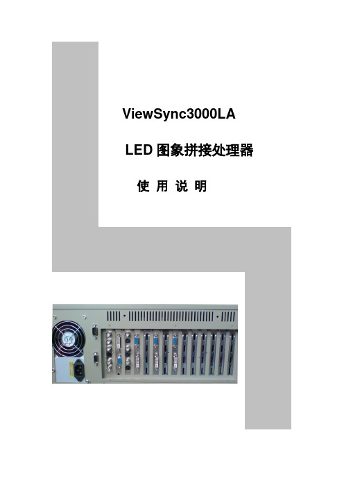
ViewSync3000LA LED图象拼接处理器使用说明目录一、安全注意事项------------------------------------------------------------------- 3二、硬件构架1、系统构架简介--------------------------------------------------------------------- 42、主输入端口------------------------------------------------------------------------ 53、子输入端口------------------------------------------------------------------------ 54、输出端口--------------------------------------------------------------------------- 55、输入输出端口图示--------------------------------------------------------------- 6三、调整设置与操作1、操作软件说明------------------------------------------------------------------ 82、输出图像的拼接调整设置-----------------------------------------------------123、同步模式设置--------------------------------------------------------------------164、主输入画面的画中画设置-----------------------------------------------------16四、技术规格--------------------------------------------------------------------------192一、安全注意事项!危险处理器内有高压,非专业维修人员不得打开后盖,以免发生危险。
LED显示屏调试软件NovaLCT多媒体播放器用户指南英文版

NovaLCTLED Configuration ToolMultimedia PlayerUser GuideProduct Version: V5.1.0Document Number: NS110100572XI 'AN N OVA S T AR T EC HCO .,L T D.Copyright © 2018 Xi’an NovaStar Tech Co., Ltd. All Rights Reserved.No part of this document may be copied, reproduced, extracted or transmitted in any form or by any means without the prior written consent of Xi’an NovaStar Tech Co., Ltd.Trademarkis a registered trademark of Xi’an NovaStar Tech Co., Ltd.StatementYou are welcome to use the product of Xi’an NovaStar Tech Co., Ltd. (hereinafter referred to as NovaStar). This document is intended to help you understand and use the product. For accuracy and reliability, NovaStar may make improvements and/or changes to this document at any time and without notice. Any problem in use or any good suggestion, please contact us through ways provided in the document. We will do our utmost to solve the problems and adopt the suggestions after evaluation as soon as possible.X I'A NN OV AS TA RT EC HC O.,LT D.Table of ContentsTable of Contents ............................................................................................................................ ii 1 System Overview .......................................................................................................................... 1 2 Software Installation .................................................................................................................... 2 3 Terminal Connection .................................................................................................................... 3 4 Function Overview ....................................................................................................................... 4 5 Main Functions of NovaLCT (7)5.1 Screen Configuration ................................................................................................................................... 7 5.1.1 Start with System Configuration Files....................................................................................................... 7 5.1.2 Start LED Display Manually ...................................................................................................................... 8 5.1.3 Set Cabinet Information .......................................................................................................................... 18 5.1.4 Adjust the Performance Parameters....................................................................................................... 20 5.1.5 Save Settings to Flash ............................................................................................................................ 28 5.1.6 Save/Load Configuration Files ............................................................................................................... 28 5.2 Adjust Brightness ....................................................................................................................................... 30 5.3 Multi-function Card Management .............................................................................................................. 32 5.3.1 Multi-function Card Configuration ........................................................................................................... 32 5.3.2 Power Management................................................................................................................................ 33 5.3.3 Monitor Data ........................................................................................................................................... 36 5.3.4 External Device ....................................................................................................................................... 37 5.3.5 Load Program ......................................................................................................................................... 37 5.4 Prestore Screen ......................................................................................................................................... 40 5.5 Advanced Color Configuration ................................................................................................................... 41 5.6 Adjust Screen Effect .................................................................................................................................. 44 5.7 Brightness and Color Calibration ............................................................................................................... 45 5.7.1 Online Calibration ................................................................................................................................... 45 5.7.2 Coefficients Management ....................................................................................................................... 46 5.7.3 Double Calibration Coefficients .............................................................................................................. 64 5.7.4 Manage Coefficients ............................................................................................................................... 65 5.8 Screen Control .......................................................................................................................................... 65 5.9 Hardware Monitoring ................................................................................................................................. 66 5.9.2 Refresh Period ........................................................................................................................................ 67 5.9.3 Hardware Configuration .......................................................................................................................... 67 5.9.4 Alarm Configuration .. (69)XI 'AN NOVA S T AR T EC HCO .,L T D.NovaLCT LED Configuration ToolMultimedia Player Configuration Guide Table of Contents5.9.5 Control Configuration (70)5.9.6 Email Setting (71)5.9.7 Email Log (72)5.10 Led Error Detection (73)6 Receiving Card Relay (77)7 Configuration Information Management (78)8 Module ID Settings (79)9 Troubleshooting (81)9.1 NovaLCT shows "No Hardware" on corresponding pages (81)9.2 NovaLCT shows "No Screen" on corresponding pages (81)9.3 The LED display does not show the image correctly during the Smart Setting procedure (81)9.4 Only a part of the modules of each cabinet work normally in Smart Setting (81)9.5 Permission Error (82)9.6 Failure to install previous versions (85)X I'A NN OV AS TA RT EC HC O.,LT D.Multimedia Player Configuration Guide 1 System Overview1 System OverviewNovaStar multimedia players are designed for small and medium size LED full colordisplays. This kind of players can be widely used in LED commercial display fields,such as light pole screens, chain store screens, advertising machines, mirrorscreens, retail store screens, door head screens, on-board screens and the screensrequiring no PCs.NovaLCT is the display configuration software running on Windows. In multimediaplayer applications, NovaLCT can work in conjunction with receiving cards,monitoring cards and multi-function cards to enable smart setting, brightnessadjustment, power control, LED error detection and hardware monitoring of the LEDscreen. The user can easily control all the key information of the screen with acomputer to get the optimal display at any time.The typical networking of the multimedia player is shown in Figure 1-1.Figure 1-1 Typical NetworkingX I'A NN OV AS TA RT EC HC O.,LT D.2 Software InstallationPreconditions●Have prepared a PC with Windows system installed.●Have obtained the installation package "NovaLCT V5.1.0.zip" from NovaStarofficial website www.novastar.tech.●Have disabled antivirus software.InstallationFirstly please unzip the installation package "NovaLCT V5.1.0.zip", then double-click"NovaLCT V5.1.0.exe" and follow the installation wizard to complete the softwareinstallation. If the firewall prompt appears, please select to allow the installation.X I'A NN OV AS TA RT EC HC O.,LT D.3 Terminal ConnectionStep 1 Open NovaLCT and choose User > Media Player Login.The system automatically searches the multimedia players in the same networksegment and then displays them in a specified sorting order.Step 2 Click the terminal name in the terminal list.Step 3 Click Connect System.Step 4 Enter user name and password for logging in the terminal, and click OK.If the login is successful, the interface below will appear, as shown in Figure 3-1.Figure 3-1 Successful login interfaceX I'A NN OV AS TA RT EC HC O.,LT D.4 Function OverviewShortcut button:This is used for configuration of the LED screens.Shortcut button:This is used for adjusting the LED displaybrightness. There are two ways for brightnessadjustment, automatic brightness and manualbrightness.Shortcut button:This is used to open the page for Multi-functioncard configuration.X I'AA RT EC HC OD.Shortcut button:Calibrate the screen and manage the calibration coefficients.Screen Control Shortcut button:Perform the screen control functions which include "Black Out", "Freeze" and "Normal". Besides, self test options are also provided.Shortcut button:Enter the monitoring page to view the monitoring results or set the monitoring parameters.Shortcut button:To open the page which all test tools (test content) for LED displays testing are in.X I'AA RT EC HC O.,LT D.X I'A NN OV AS TA RT EC5Main Functions of NovaLCT5.1 Screen Configuration5.1.1 Start with System Configuration FilesThe advantage of using system configuration files to configure LED displays is that the configuration procedure is very simple and easy, and no manual configuration operation is required.Step 1 Click on the main interface, and the Screen Configuration windowpops up as shown in Figure 5-1.Figure 5-1 The Screen Configuration windowStep 2 Select the Load Config File option, use the Browse button to select the system configuration file to be loaded. Step 3 Click Next .The LED display system will have been configured when the load operation is finished.XI 'AN N OVA S T AR T EC HCO .,L T D.5.1.2 Start LED Display Manually5.1.2.1 Smart SettingsStep 1 Clickon the main interface and select Screen Configuration .Step 2 Click Next and the window below will pop up.Figure 5-2 The Screen Configuration window● Quantity of ScreensThis is the number of LED displays that are to be configured. ●ConfigureThis button is used to load the Screen Number to the NovaLCT application.●Read form HWThis is used for the application to read the LED display information from thehardware.●Detect Communication StatusXI 'AN N OVA S T AR T EC HCO .,L T D.This is used to check whether the communication within the current LED display is good.●Read the Number of Receiving CardsGet the number of receiving cards loaded by each of the Ethernet ports of the current multimedia player.●Enable Mapping (only supported by some receiving cards of the Armor series) When this function is opened, current serial number of the cabinet and its Ethernet port No. will be shown on the cabinet.●Load from FileLoad screen information files save on control computer. ●Save to File This is used to save screen information files as screen information file (*.scr).●Send to HWThis is used to send the LED display configuration settings to the connected multimedia player.●SaveThis is used to save the settings to a FLASH chip. The saved data won’t be lost even the hardware is powered off.●Save System Configuration FileSave system configuration parameters as a file.Step 3 Click Smart Settings under the Receiving Card tab, and the Smart SettingsSelection window pops up as shown in Figure 5-3.Figure 5-3 The Smart Setting dialogStep 4 Select Option 1 and click Next to activate smart setting wizard. The Smart Settings Guide 1 window will appear, as shown in Figure 5-4.XI 'AN N OVA S T AR T EC HCO .,L T D.Figure 5-4 Smart Settings Guide 1●Module ChipSelect the driver chip type from the list according to what is actually used for the cabinets.●Data TypeSelect the data type from the list.●Module typeThe option can be regular module or irregular module. If it is set to be irregularmodule, the counts of driver chips for one data set and one color should be given.● Quantity of PixelsThis is the size of the real pixel array of a module. ● Row Decoding TypeThis list provides multiple options. You can choose one based on the module. ●HUB ModeSelect the Hub mode of the receiving card, which could be normal, 20 groups, 24 groups and 28 groups.XI 'AN N OVA S T AR T EC HCO .,L T D.Step 5 Click Next to access Smart Settings Guide 2. Shown in Figure 5-5 is the SmartSettings Guide 2 window.Figure 5-5 Smart Settings Guide 2Step 6 Click Next to access Smart Settings Guide 3. Shown in Figure 5-6 is the SmartSettings Guide 3 window.Figure 5-6 Smart Settings Guide 3Step 7 Complete the settings in Smart Settings Guide 3 according to the actual situation, and click Next to access Smart Settings Guide 4. Shown in Figure 5-7 is the Smart Settings Guide 4 window.XI 'AN N OVA S T EC HCO .,L T D.Figure 5-7 Smart Settings Guide 4Step 8 Complete the settings in Smart Settings Guide 4 according to the actual situation,and click Next to access Smart Settings Guide 5. Shown in Figure 5-8 is the Smart Settings Guide 5 window.Figure 5-8 Smart Settings Guide 5Step 9 Complete the settings in Smart Settings Guide 5 according to the actual situation,and click Next to access Smart Settings Guide 9. Shown in Figure 5-9 is the Smart Settings Guide 9 window.Click the corresponding grids according to the position of the lightened lights until no light is lightened any more. A line of the lightened lights routing will be drawn at the same time.XI 'AN N OVA S T AR T EC HCO .,L T D.Figure 5-9 Smart Settings Guide 9Note:Hold the left button of the mouse and drag, or use Tab and Enter to draw the routing line. Use Automatic Generation button to accomplish drawing routing lines of the same pattern. Clickorto zoom out or in the module layout.Step 10 A message indicating the finish will be shown when enough lights have beenprocessed. Click OK .Step 11 Click Next and a message pops up indicating the settings are completed, then clickOK .The Save Module Information dialog is shown in Figure 5-10. Saving the module settings to files will make it easier to perform module configuration for another LED displays constructed by modules which require the same settings as the one just set (Option 2 or Option 3 in Figure 5-3). Click Finish directly if you don't want to save the settings.XI 'AN N OVA S T AR T EC HCO .,L T D.Figure 5-10 The Save Module Information dialog5.1.2.2 LED Display ConfigurationSelect Screen Connection page in the Screen Configuration window (Figure 5-2). If no LED display has been configured (Figure 5-11), please enter screen number (number of the LED displays to be configured) and click Configure button. The default screen configuration page (page for simple LED display configuration) will open.The configuration information will be shown on the Screen Configuration page if a LED display has been configured. Modify the settings and send them to hardware if necessary.Figure 5-11 No LED display configuration informationScreen types include standard screen and complex screen. Configurations for different types of screen will be given as follow.XI 'AN N OVA S T AR T EC HCO .,L T D.Standard Screen ConfigurationSet the cascade type of receiving cards manually. The load of each receiving cards can be different.Figure 5-12 Standard screen configuration page● CoordinateThis is the upper-left corner of a rectangular area of the computer display. Therectangle area of the computer display is called mapping area. Content inside the mapping area will be shown on the LED display. The default location is (0, 0), which is actually the upper-left corner of the computer display. ●Virtual ModeSpecify the pixel mode of the LED display. The option could be real pixel or virtual 3 lights or virtual 4 lights.Check Enable to enable virtual mode, click to enter into the settinginterface of the virtual mode. Select the layout type of the lights on the top right corner of the window, and drag the mouse on the left side of the window to change the arrangement of the lights.For example, if the Rectangle is selected, the changed positions are as follows.XI 'AN N OVA S T AR T EC HCO .,L T D.Figure 5-13 Positions of the virtual lights before changeFigure 5-14 Positions of the virtual lights after change● Receiving Card Columns/RowsThese are the numbers of columns and rows of the scan board (receiving card)array of the LED display. A sketch map of the scan board array will be shown in this page after these two parameters are set. ● Reset AllThis button is used to reset all cabinet settings and connection settings. ●Hidden WiringAfter selecting this function, the re ceiving card’s wiring in the following topology will be hidden.●XI 'AN N OVA S T AR T EC HCO .,L T D.This is a mark for receiving card classification. Select one receiving card and click on the drop-down box to choose one color from red, green and blue, and then click on the given receiving card to add the mark.●Sending Card Number No settings are required. ●Ethernet Port No.Select an Ethernet port of the multimedia player. Click Read the Number of Receiving Cards and hover over the port with your mouse. The number of receiving cards loaded by the port will be displayed.●BackThis button is used to clear all settings related to the last set multimedia player.●Clear Current Output Port This button is used to clear all settings related to the current output port.●Width/HeightThese are the width and height of the pixel array of the current receiving card.●Apply to Entire ColumnSelect a receiving card, and set the width the same as the loading width of the column the selected receiving card belonged to.●Apply to Entire RowSelect a receiving card, and set the height the same as the loading height of the line the selected receiving card belonged to.●Apply to the Current PortClick this button to set the pixel array sizes of all receiving cards connected to the current Ethernet port the same as that of the current receiving card.●Set BlankSelect this if the current position (pixel array of the current receiving card) needs to be left unset.●Quick ConnectionQuickly set cabinet connection. In Quick Connection , select a connection type.Drag the mouse to select the receiving cards corresponding to the output port. The connection is done automatically.Complex Screen ConfigurationSet the multimedia player, Ethernet port, start coordinates and pixels to be loaded of each of the corresponding receiving cards.XI 'AN OVA S T AR T EC HCO .,L T D.Figure 5-15 Complex screen configuration page●AddClick Add to access the window for receiving cards information setting, such as Ethernet output ports, pixel array sizes and so on.●Edit To edit the information that has been set for receiving cards.●Delete To delete the selected receiving card from the receiving cards list.●ClearTo delete all receiving cards from the list.5.1.3 Set Cabinet Information Pixel array size and module cascade direction can be set in this panel.Select the Receiving Card page in the Screen Configuration window (Figure 5-2). Figure 5-16 is the receiving card page.XI 'A N N O VA S T AR T EC HCO .,L T D.Figure 5-16 Cabinet information settingsNote that the Regular panel is for regular cabinets parameters setting and the Irregular panel is for irregular cabinet parameters setting.●Cabinet rotation: Set image rotation angle to 0°, 90°, 180° or 270°. ● Width/HeightThese two items specify the width and height of the cabinet pixel array. ● Maximum WidthMaximum width varies with parameters of refresh rate, gray scale levels, andshift clock frequency. Normally, the higher the refresh rate is and the finer the gray scale levels are, the smaller the maximum width will be; while the higher the shift clock frequency is, the larger the maximum width can be. But as the shift clock frequency is limited by driver chips and module design, the maximum width is also limited. ●Maximum HeightThe Maximum Height depends on the module design.XI 'AN N OVA S T AR T EC HCO .,L T D.5.1.4 Adjust the Performance ParametersTo achieve the best performance, performance parameters should be set properly. The area marked with 2 in the Performance Settings panel in Figure 5-16 is shown in Figure 5-17.Figure 5-17 The Performance Setting panelEliminate Afterglow : Some of chips are supporting the functions of eliminating afterglow, and the software defaults to be ticked.Data group exchangeAdjust the order of the data groups.There are intuition and group data group exchange modes.● As shown in Figure 5-18, in intuition mode, fill out on software based on theorder displayed on the screen.● As shown in Figure 5-19, in group mode, click proper positions in sequenceaccording to block flashing orders on the screen. Simultaneously, corresponding series numbers are generating to display the area without flashing block, and click No flashing area .● : Clear current data, and reset. ●: Send data to hardware. ●: Save current data.XI 'AN N OVA S T AR T EC HCO .,L T D.Figure 5-18 Intuition modeFigure 5-19 Group modeMore settingsSymmetrical/Data Group ExtensionXI 'AN N OVA S T AR T EC HCO .,L T D.Figure 5-20 More settings−Output ModeSymmetrical OutputsIf selected, the two 50-pin output ports of a scan board will work for the left and the right half of the cabinet pixel array respectively.Triple Strip OutputsBeing optional, and after being selected, the loaded box will be dividedinto three parts from left to right.Quadruple Strip OutputsBeing optional, and after being selected, the loaded box will be dividedinto four parts from left to right.−Data Group ExtensionTwenty Data GroupsIf selected, the scan board will provide 20 sets of output data for the cabinet.Twenty Four Data GroupsIf selected, the scan board will provide 24 sets of output data for the cabinet.Twenty Eight Data GroupsXI 'AN N OVA S T AR T EC HCO .,L T D.If selected, the scan board will provide 28 sets of output data for the cabinet.32 sets of dataIf selected, the scan board will provide 32 sets of output data for the cabinet.−Ghost Control SignalSignal SwitchThe On or Off could be selected.Signal PolarityThe polarity of the signal could be selected according to the design of the afterglow circuit.−Hub ModeSelect the Hub mode of the receiving card, which could be divided into normal, 20 groups, 24 groups or 28 groups .−Graphics OutputThe output in the scanning direction or the output in the reverse direction could be selected.●Monitoring Card Data Line AdjustmentIf the monitoring corresponding signals are mismatched when the monitoring card HUB is connected to the receiving card, the corresponding signal of each monitoring data line can be adjusted manually.●Additional FunctionEliminate the afterglow of the insolated points, and shut down the indicators of the receiving card, Shorten the synchronization time, Brightness slowly brighten, and EMC Function.●Flash ArrangementFigure 5-21 is the physical connection schematic diagram of Flash. According tothat diagram, the sequence number of BUS is determinedly selector. Users shall consult HUB board designer for connection of the flash module to confirm the sequence number of BUS. One BUS can be cascaded with multiple modules. The MOM Topology can be set on the software according to the actual order of connection.XI 'AN N OVA S T AR T EC HCO .,L T D.Figure 5-21 Physical connection schematic diagram of FlashAs shown in Figure 5-22, to set MOM Topology on the software, firstly setFLASH row and column numbers, and then click anywhere on the right side of the window, select the corresponding BUS, and based on the actual route, click the left button of the mouse or press the arrow key to set each piece of Flash information according to the order (control size and coordinates).Select a BUS and set Flash control size, and then click "Apply to current BUS";the size of Flash with BUS connection will be modified as the current value.After Flash Control Size is set, click Reset All, and then all Flash Control Sizes will be reset as the size set currently.X I'A NN OV AS TA RT EC HC O.,LT D.Figure 5-22 MOM Physical SettingMonitoring Card Data Set ExchangeMonitoring card data set exchange function supports the exchange of serial 16-set data, serial 20-set data, and parallel 64-set data. In case of an incorrect HUB connection with data set exchange being set in Data group exchange, settings thereof must be served as reference to modify the corresponding information of the monitoring card data set.Set data type in Smart Settings or set data set expansion in Symmetrical/DataGroup Extension . When it is set to parallel 16-set or 20-set data, the system will supply 16-set or 20-set data exchange for the monitoring card. When it is set to serial 24-set or 28-set data, the system will supply a 64-line monitoring card data set exchange configuration window.Select Enable monitoring card data set exchange to make it work after exchange data configuration.XI 'AN N OVA S T AR T EC HCO .,L T D.。
【免费下载】600MW超临界汽轮机DEH说明书上汽提供 rev1

600MW超临界机组DEH系统说明书1汽轮机概述超临界600/660MW中间再热凝汽式汽轮机主要技术规范机组型号单位N600-24.2/566/566N600-24.2/538/566N660-24.2/566/566额定功率MW600600660最大连续MW648648711功率额定进汽MPa(a)24.224.224.2压力额定进汽℃566538566温度再热进汽℃566566566温度工作转速r/min300030003000额定背压K Pa(a) 4.9 4.9 4.9注意:上表中的数据为一般数据,仅供参考,具体以项目的热平衡图为准。
由于锅炉采用直流炉,再热器布置在炉膛较高温区,不允许干烧,必须保证最低冷却流量。
这就要求在锅炉启动时,必须打开高低压旁路,蒸汽通过高旁进入再热器,再经过低旁进入凝汽器。
而引进型汽轮机中压缸在冷态启动时不参与控制,仅全开全关,所以在汽轮机冷态启动时,要求高低旁路关闭,再热调节阀全开,主蒸汽进入汽轮机高压缸做功,经高排逆止门进入再热器,经再热后送入中低压缸,再进入凝汽器。
由于汽轮机在启动阶段流量较小,在3000r/min 时只有3-5%的流量,远远不能满足锅炉再热器最低的冷却流量。
因此,在汽轮机启动时,再热调节阀必须参加控制,以便开启高低压旁路,以满足锅炉的要求。
所以600MW超临界汽轮机一般要求采用高中压联合启动(即bypass on)的启动方式。
2高中压联合启动高中压缸联合启动,即由高压调节汽阀及再热调节阀分别控制高压缸及中压缸的蒸汽流量,从而控制机组的转速。
高中压联合启动的要点在于高压缸及中低压缸的流量分配。
启动过程如下:2.1 盘车(启动前的要求)2.1.1主蒸汽和再热蒸汽要有56℃以上的过热度。
2.1.2 高压内缸下半第一级金属温度和中压缸第一级持环下半金属温度,大于204 ℃时,汽轮机采用热态启动模式,小于204℃时,汽轮机采用冷态启动模式,启动参数见图“主汽门前启动蒸汽参数”,及“热态起启动的建议”中规定。
Sensotec TensiMaster 3000 产品说明书

Provides the ultimate solution for measuring and monitoring precise tension on web process or wire machinery in demanding industrial environments•For use with pillow block bearingsand rotating shaft installations.•Washdown-duty, withstanding impinging liquids and wet environments.•Designed to comply withNEMA 4x, IP65/67 standards.•Completely sealed. Corrosion-resisting and chemical-resisting (Stainless Steel 410 or Anodized Aluminum Alloy 6061).•Competitively priced againstcommon non-sealed,non-corrosive and chemical resistive designs.•Compact low-profile design fits easily into tight places.•With an end connector design(instead of on the side), no need for a left hand and right hand configuration.•Available in a variety of loadcapacities (25 to 30,000 lb.)and sizes (6.5 to 17 inches long),suiting a wide range of applications.•Provides 500% overload protection.•Easily mounted at any angle.•Convenient mounting plate for easy installation of pillow block bearing.Performance BenefitsThe UPB (Under-Pillow-Block)Washdown-Duty LC (load cell) is part of the Cleveland-Kidder ®Tension Transducer product family. It sets the standard for under-pillow-block tension transducers for the web process industry.The UPB Washdown-Duty LC has a completely sealed corrosion-resisting design, making it ideal for use in demanding industrial environments,including the production of paper, steel,textiles, roofing shingles, linoleum,rubber, foil, and food products.The UPB Washdown-Duty LC can be mounted at any angle. Its web force direction is not restricted to being either parallel or perpendicular to the UPB top surface (common with other load cell designs). Its compact low profile design makes it perfect for use in both retrofit and OEM applications.The UPB Washdown-Duty LC is a solid one-piece design, providing a high natural frequency response with a high level, linear output signal.Design FeaturesThe Cleveland-Kidder UPB Washdown-Duty LC is an under-pillow-block load cell that has been designed formeasuring and monitoring tension on web process and wire machinery in demanding environments.The UPB Washdown-Duty LC is made from a solid block that results in a completely sealed design with a very low profile. It is typically applied in pairs,one under each of the supporting guide roll’s pillow block bearings. Mounting the pillow block bearing to the UPB Washdown-Duty LC is simple and convenient:Rather than having to drill into the top of the load cell, the UPB Washdown-Duty LC uses a convenient mounting plate, making installation andreplacement easier. Held in place by four corner bolts, the mounting plate is easily removed, drilled and tapped to match the pillow block mounting dimensions. The plate is then remounted and the pillow block bearing is bolted into place.To assure maximum corrosion and chemical resistance, the UPBWashdown-Duty LC is made from either Stainless Steel or Aluminum Alloy depending on the size rating.Displacement from loads is negligible (typically 0.002 in.) and the output is temperature compensated.UNDER PILLOW BLOCK WASHDOWN-DUTY LOAD CELLUPB Washdown-DutyLCSIZE RATING (LB) * ULTIMATE OVERLOAD (%)UPB125 to 1000500UPB21000 to 1000050020000250UPB310000 to 30000500INDUSTRIAL PRODUCTSDIMENSION TABLESRATINGSSize Dimensions in Inches*Maximum No.Working Force (lb.)A B C D E F(Max.)G H J(Max.)KL M N WUPB1 1.50.55 5.8 1.55/16(4) 5.8 1.6 1.951/2 1.40 6.5 1.3 2.2 2.2 25, 50, 100, 250, 500, 1000UPB230.8010.0 3.01/2 (4)10.0 3.0 2.473/4 1.6811.0 3.3 3.95 4.01000, 2500, 5000, 10000, 20000UPB3 4.51.6315.04.51 (4)15.6 5.04.21-1/8 2.8017.04.85.26.510000, 20000, 30000Size Dimensions in Millimeters*MaximumNo.Working Force (N)**A B C DE F(Max.)G H J(Max.)KLM N WUPB13814147.538M814740.549.5M1235.5165335656 110, 225, 450, 1100, 2250, 4500UPB2762025476M122547663M2042.5279.584100101.54500, 11000, 22000, 45000, 90000UPB311441.5381114M24396127106.5M307143212213216545000, 90000, 135000Weight lb. (kg.) Each UPB1UPB2UPB33.7 (1.7)22 (10)102 (47)*Ultimate overload: Maximum force applied on the transducer without risking permanentdeformation. For the Washdown duty UPB the output is linear up to the point of the ultimate overload.*Allow 2.5 inches clearance (64mm) for connector.**Approximate rating in Newtons.INDUSTRIAL PRODUCTS SPECIFICATIONSMaterial: Body: Size 1- Anodized Aluminum Alloy 6061Size 2 & 3 Stainless Steel 410Mounting Plates: Stainless Steel 304Bolts for Mounting Plates: Stainless Steel Gage Resistance:Each transducer contains a half-bridge,having a nominal end-to-end resistance of440-480 Ohms.Gage Factor:100 nominalExcitation Voltage:10 VDC or VAC (rms) maximumOutput Signal@ Rated M.W.F.: 100 mV nominal / transducer200 mV nominal / pair(With 10 VDC or VAC rms excitationvoltage)OperatingTemperature Range:0˚F to 200˚FSensitivity Changewith Temp.Less than 0.02% of rated outputtypicalHumidity:95% R.H.CombinedNon-linearityAnd hysteresis:±0.5% maximum of rated output Repeatability:±0.2% maximum of rated output“MS” Connectors:MS-3102E-10SL-3P(Sealed 3 Pin Connector)Input Impedancerequired:5K Ohms per transducer(TransducerSignal Amplifierif not CMCsupplied)Output impedance:880 Ohms for UPB2 and UPB3120 Ohms for UPB1UNDERPILLOWBLOCKWASHDOWN-DUTYLOAD CELLUPBWashdown-DutyLCProcedure for Mounting the UPB Load Cellto the Machine Frame (see picture above)Remove the pillow block mounting plate (it is held in place by four stainless steel corner bolts) in order to gain access to the four load cell mounting holes. Drill and tap the machine frame to match the load cell mounting holes. Note: The UPB must be oriented so that the resultant tension force direction (bisector of the wrap angle) isin the same quadrant as the load direction arrow on the side of the UPB.Bolt the load cell in place. The UPB load cell is designed so that either imperial or metric mounting bolts can be used when mounting the load cell to the machine frame. Refer to E in the Dimensions Table for the proper bolt size. Before remounting the pillow block mounting plate refer to the procedure below.Procedure for Mounting the Pillow Block Bearing to the UPB Load Cell (see picture above)Mounting the pillow block bearing to the UPB is simple and convenient. The UPB is offered with a pillow block mounting plate. The mounting plate is held in place by four stainless steel corner bolts. Remove the mounting plate, then drill and tap it to match the pillow block mounting dimensions. A centerline mark is provided on the mounting plate. The plate is to be drilled and tapped by utilizing this centerline mark to insure that the pillow block bearing is centered on the plate. Remount the plate and bolt the pillow block bearing to it. The mounting plate is 304 Stainless Steel, which is amenable to drilling but offers corrosive and chemical resistance. Refer to Jin the Dimensions Table for the maximum bolt diameterrecommended for bolting the pillow blockbearing to the mounting plate.INDUSTRIAL PRODUCTSUNDER PILLOW BLOCK WASHDOWN-DUTY LOAD CELLUPB LCSIZING CALCULATIONSIZING CALCULATION:ORDERING PROCEDURE:SELECTION CHARTT =Max Tension A =Wrap Angle (Degrees)W =Roll Weight B =Angle of Tension Force (Degrees)K =Overload for Transients(Nominally 1.4 for most applications)MWF = Maximum Working Force(This is used to select the proper force rating of the transducer)C =Mounting Angle H =Bearing Height + DSIZE L (in.) D (in.)UPB1 2.50.98UPB2 4.5 1.25UPB36.52.10A[2KT sin —][HsinB + LcosB] ±W[L cosC – HsinC]**2*The MWF calculation defines the force on each individual load cell.**If Angle B is below horizontal use + in calculation. If Angle B is above horizontal use - in calculation Note: Consult CMC for assistance in sizing the load cell to your specific application.1. Calculate the Maximum Working Force (MWF)rating based upon your calculations from the sizing calculation equation.2. From the Selection Chart,determine the part number for the UPB Washdown-Duty LC. Select a MWF rating that equals or exceeds the MWF from your sizing calculation. Then, make sure that your pillow block bearing fits the UPB type that you selected (UPB 1, 2,or 3).Example: If you calculate a MWF of 2,204 lbs., select a UPB 2 rated at 2,500 lbs.MWF from the Selection Chart. Your part number is M846-12172-100. Then,from the Dimensions Table,make sure that your pillow bearing fits on the Size 2transducer. If it does not,please consult factory.3. Obtain pricing and delivery information by contacting a CMC sales representative,distributor, or the factory.ACCESSORIESACCESSORIES CHART*Load Cell Cable The load cell cable end is provided with a straight or right angle connector as specified. The controller end is provided with tinned leads. The controller end of the cable can be cut to length if the standard length provided is not the exact length required.MWF* =2LTransducer MWF (lbs.)UPB1Rating25501002505001000Part No. M846-12171-000100200300400500UPB2Rating1000250050001000020000Part No. M846-12172-000100200300400UPB3Rating100002000030000Part No. M846-12173-000100200Cable Length Part Number - Straight Connector Part Number - Right Angle Connector 20 Feet MO-01948-020MO-01957-02025 Feet MO-01948-025MO-01957-02550 Feet MO-01948-050MO-01957-05075 Feet MO-01948-075MO-01957-075100 Feet MO-01948-100MO-09157-100150 FeetMO-01948-150MO-01957-150*Cables are not washdown-duty. For washdown-duty cables consult CMC.。
LA3000系列二合一分析仪使用手册说明书

BusFinder系列. LA3000系列二合一分析仪(协议+逻辑)使用手册Publish: 2018/06目录第一章安装与设置 (4)硬件安装 (4)主机外观与功能说明 (4)LA探头 (5)eMMC5.1探头(选配) (6)NAND Flash探头(选配) (7)SD 3.0探头(选配) (8)SD 4.0(uSD 4.0)探头(选配) (9)软件安装 (10)第二章功能列表与操作 (12)协议分析仪 (12)档案 (12)采集 (13)显示波形 (20)搜寻 (20)到末尾 (21)窗口 (21)保存成文本文件 (21)细节窗口 (22)统计窗口 (23)隐藏数据窗口 (23)叠加示波器 (24)光标 (25)逻辑分析仪 (26)档案 (27)采集 (32)采集模式设置 (45)光标 (49)波形区 (52)报告区 (53)总线解碼设置 (54)自定义报告设置 (54)第三章技术支持 (55)附录一探头尺寸规格及脚位定义 (56)LA探头 (56)eMMC5.1探头 (58)NAND Flash探头 (60)SD3.0探头 (61)SD4.0(uSD4.0)探头 (63)附录二Tuning settings (64)第一章安装与设置硬件安装主机外观与功能说明❶插槽(Socket A)❷插槽(Socket B)❸SD 4.0数据传输插孔,此为USB 3.0 Type A 插孔,使用USB 3.0传输线(75cm),仅作为连接SD 4.0转板用,LA3000系列不适用❹指示灯,有2种用途a.绿灯:只有电源与USB传输线都正确接好上电之后,指示灯才会亮起b.红灯:设备正于忙碌中时显示红灯长亮或闪烁❶DC 12V电源插孔❷USB 3.0 Type B传输线插孔,连接计算机用.❸触发输入(Trigger In)插孔❹触发输出(Trigger Out)插孔❺同步参考频率输入(Reference clock)插孔❻同步参考频率输出(Reference clock)插孔探头安装方式推入:将探头持平正对主机插槽,用力平均的将探头推入,听到喀嚓声即安装完成。
SVC3000用户手册

SmartView Clinet 3000用户手册目录1运行环境 (1)1.1硬件设备 (1)1.2支持软件 (1)2 软件安装 (2)3 登录 (4)4 设备管理 (5)4.1 新增设备 (6)4.2 搜索设备 (6)4.3 删除设备 (8)4.4 设备信息变更 (8)5 用户管理 (9)5.1 认证文件管理 (9)5.2 用户组管理 (10)5.3 用户管理 (13)6 会话管理 (14)6.1 启动会话 (14)6.2 终止会话 (15)6.3 会话设置 (16)6.4 鼠标 (17)6.5 键盘 (17)6.6 选项设置 (18)6.7 全屏 (19)6.7 虚拟媒体 (19)6.8 智能电源管理器(PDU)管理 (20)6.8.1 PDU 信息变更 (20)6.8.2 PDU控制 (21)1运行环境1.1硬件设备中央处理器:主频1GHz以上,推荐使用英特尔“奔腾4”以上处理器内存:256MB以上内存硬盘:200M以上可用硬盘空间显示:标准 VGA,16位真彩色以上驱动器:CD-ROM驱动器(可选)1.2支持软件操作系统:Windows XP或更高版本2 软件安装【第一步】启动计算机,并将《SmartView Client 3000》安装盘放入光驱。
单机版文件名:SVC3000(STAND)_Setup,网络版分为32位、64位,请按需求安装。
【第二步】点击“下一步”继续安装,读取用户许可协议【第三步】同意后点击“下一步”继续安装,安装程序出现“选择目的地位置”框,默认安装目录为C:\Program Files\COMPANY\SmartView,点击“更改”可更改安装目录,如图2.1:图2.1【第四步】点击“下一步”进入软件安装过程,如图2.2:图2.2出现如图2.3所示,表示安装成功图2.33 登录双击桌面上的图标,进入SVC3000系统,也可以从【开始】→【程序】→【SVC3000】进入。
InvenSense MPU-3300 3-Axis Evaluation Board用户指南说明书
MPU-3300 EVBMPU-3300 EV Board User GuideDocument Number: AN-MPU-3300EVB-00 Revision:1.0Release Date: 06/13/2012InvenSense, Inc., 1197 Borregas Ave., Sunnyvale, CA 94089, USA 1 AN-MPU-3300EVB-00MPU-3300 3-AxisEvaluation Board User GuideRevision 1.0MPU-3300 EV Board User GuideDocument Number: AN-MPU-3300EVB-00 Revision:1.0Release Date: 06/13/2012InvenSense, Inc., 1197 Borregas Ave., Sunnyvale, CA 94089, USA 2 AN-MPU-3300EVB-00 CONTENTS1. REVISION HISTORY .................................................................................................................................. 3 2. PURPOSE ................................................................................................................................................... 4 2.1 U SAGE .................................................................................................................................................... 4 2.2 R ELATED D OCUMENTS ............................................................................................................................. 4 3. MPU-3300 3-AXIS EV BOARD OVERVIEW . (5)3.1 MPU-3300 K EY F UNCTION AND P IN -OUTS ................................................................................................ 6 3.2 MPU-3300 B US C ONNECTION .................................................................................................................. 6 4. MPU-3300 3-AXIS EVB SCHEMATICS . (7)4.1 B ILL OF M ATERIALS .................................................................................................................................. 8 4.2 P OWER S UPPLY C ONNECTIONS ................................................................................................................ 8 4.3 MPU-3300 EVB CONNECTOR SIGNALS DESCRIPTION ................................................................................ 9 4.4 C ONNECTING THE FSYNC L INE .............................................................................................................. 11 4.5 S ERIAL BUS L EVELS , S PEEDS AND T ERMINATIONS ................................................................................... 115. DATA GATHERING OPTIONS ................................................................................................................. 11 5.1C ONNECTION TO ARM EVB (12)5.2 Use of MPU-3300 without ARM EVB....................................................................................12 6. SPECIAL INSTRUCTIONS ....................................................................................................................... 12 6.1 E LECTROSTATIC D ISCHARGE S ENSITIVITY .. (12)7. COMPONENT PLACEMENT .................................................................................... (12)MPU-3300 EV Board User GuideDocument Number: AN-MPU-3300EVB-00 Revision:1.0Release Date: 06/13/2012InvenSense, Inc., 1197 Borregas Ave., Sunnyvale, CA 94089, USA 3 AN-MPU-3300EVB-00 1. Revision HistoryDate Revision Description 6/13/2012 1.0 Initial releaseMPU-3300 EV Board User GuideDocument Number: AN-MPU-3300EVB-00 Revision:1.0Release Date: 06/13/2012InvenSense, Inc., 1197 Borregas Ave., Sunnyvale, CA 94089, USA 4 AN-MPU-3300EVB-00 2. PurposeThis document describes the hardware and circuitry on the MPU-3300™3-Axis Evaluation (EV) Board. It covers applications incorporating the EV board into a larger system, understanding key signals and circuit functions, hardware jumper settings, and port connectors.2.1UsageThis evaluation board provides three axes of motion sensing, comprised of:∙ X-, Y- and Z-Axis gyros with ±225°/sec and ±450°/sec selectable full-scale range. ∙Digital data measured using on-chip ADCs, is transmitted over I²C or SPI interfaces.The Evaluation board may be used by itself using either SPI or I²C serial communications interfaces. Alternatively, it may be connected to In venSense’s ARM Evaluation Board for connectivity to a host computer using the USB interface.2.2Related DocumentsThe following documents are recommended for additional information regarding the products and systems described in this Application Note.∙ MPU-3300 Product Specification∙ MPU-3300 Register Map and Register Descriptions ∙MPU-3300 EVB schematicsMPU-3300 EV Board User GuideDocument Number: AN-MPU-3300EVB-00 Revision:1.0Release Date: 06/13/2012InvenSense, Inc., 1197 Borregas Ave., Sunnyvale, CA 94089, USA 5 AN-MPU-3300EVB-00 3. MPU-3300 EV Board OverviewThe MPU-3300 EV Board contains the MPU-3300. It contains a numb er of ‘solder -across’ jumper points that permit several circuit configurations.Refer to Figure 1. The EV Board is populated on its top side only for easy measurement access. The 10x2 customer header connector is designed to connect with the InvenSense ARM Evaluation Board, which is a host microcontroller board useful for adapting the MPU-3300 EV Board to a personal computer via its USB port.Figure 1: Top side of the MPU-3300 3-Axis EV BoardThe 5x2 extension factory header is intended for connecting additional devices to the EV Board. The 3-pin power selection headers are used to select which voltage supply is applied to the MPU-3300.MPU-3300 EV Board User GuideDocument Number: AN-MPU-3300EVB-00 Revision:1.0Release Date: 06/13/2012InvenSense, Inc., 1197 Borregas Ave., Sunnyvale, CA 94089, USA 6 AN-MPU-3300EVB-00 3.1MPU-3300 Key Function and Pin-outsThe MPU-3300 EVB is a fully-tested evaluation board, providing for quick evaluation of the MPU-3300 X- , Y- , and Z-axis angular rate gyroscope. The MPU-3300 uses InvenSense’s proprietary MEMS technology with vertically driven vibrating masses to produce a functionally complete, low-cost motion sensor. All required conditioning electronics are integrated into a single chip measuring 4 x 4 x 0.9mm. It incorporates X- , Y- and Z-axis low-pass filters and an OTP (One Time Programmable) embedded memory used for factory calibration of the sensor. Factory trimmed scale factors eliminate the need for external active components and end-user calibration. A built-in Proportional-To-Absolute-Temperature (PTAT) sensor provides temperature compensation information. The product is lead-free and Green Compliant.Figure 2: MPU-3300 Package3.2MPU-3300 Bus ConnectionThe MPU-3300 communicates to a system processor using either SPI or an I 2C serial communications interface. The MPU-3300 always acts as a slave when communicating to the system processor.MPU-3300 EV Board User GuideDocument Number: AN-MPU-3300EVB-00 Revision:1.0Release Date: 06/13/2012InvenSense, Inc., 1197 Borregas Ave., Sunnyvale, CA 94089, USA 7 AN-MPU-3300EVB-004. MPU-3300 3-Axis EVB SchematicsVDDIO SelectVDD SelectU52DNS_AKM89750InvenSense3V0U54DNS_BMA1800U51DNS_BMA250/22200000000U50MPU-3300Figure 3: SchematicsMPU-3000 EV Board Application NoteDocument Number: AN-MPU3000EVB-00 Revision: 01Release Date: 9/29/10InvenSense, Inc., 1197 Borregas, Ave. Sunnyvale, CA 94089, USA 8 AN-MPU-3300EVB-00 4.1Bill of MaterialsTable 1: Bill of MaterialsItem Quantity ReferencePart PCB Footprint1 5 BP50,BP52,BP54,BP57, BP580.1uF C0402 2 1 C50 2200pF/50V C0402 3 2 C51,C52 2.2uF C0603 4 1 C53 0.033uFC0402 5 1 CN51 HEADER 14X2, Male, 90D, 2.54mmx2.54mm6 2 JP51,JP50 HEADER 3, 80mil, 180D, MaleJP2P1_8X1_3S7 1 R50 1K R0402 8 1 R53 100K R0402 9 4 R56,R57,R62,R6310KR040210 1 U50 MPU-3300, 24-Lead QFN (4mm x 4mm x 0.9mm)QFN24_4X4(0.5PITCH)111U53YB1210ST25R300SOT2354.2Power Supply ConnectionsJP550 and JP51 are 3 header-pin plug-in jumpers which allow users to select between the on-board LDO and an external DC supply for the MPU-3300. For details, please refer to Table 2: Power Selection Jumpers.The on-board 3.0V LDO (Low-dropout voltage regulator) is a low-noise version with stable enable-disable profile. Its output is called 3V0 on the schematic. Using the LDO will assure that the gyroscope and accelerometer performance will meet published specifications.Selecting the raw Vcc line to power the chip is generally done while designing and evaluating an embedded platform, where the host processor and related electronics needs full control over the motion processing chipset’s power supply.When selecting the on-board LDO (3V0) power; supply at least 3.7V to the external Vcc to ensure that the LDO works properly.When selecting to supply 5V Vcc; JP50 and JP51 must be set as “1-2 short” to supply the MPU-3300 VDD and VLOGIC operation range at 2.1V to 3.6V.MPU-3300 EV Board Application Note Document Number: AN-MPU3300EVB-00Revision: 01Release Date: 6/13/124.3 MPU-3300 EVB Connector Signals DescriptionTable 2: Power Selection Jumpers (JP51, JP50)JP50 Pin Number Signal description1-2 short VLOGIC = 3V2-3 short VLOGIC = Vcc (from external)JP51 Pin Number Signal description1-2 short VDD = 3V2-3 short VDD = Vcc (from external)InvenSense, Inc., 1197 Borregas Ave., Sunnyvale, Ca 94089, USA 9 AN-MPU-3300EVB-00 Tel: +1 (408) 988-7339 Fax: +1 (408) 988-8104 ©2012 InvenSense, Inc. All rights reserved. Website: http//Release Date: 6/13/12InvenSense, Inc., 1197 Borregas Ave., Sunnyvale, Ca 94089, USA 10 AN-MPU-3300EVB-00 Tel: +1 (408) 988-7339 Fax: +1 (408) 988-8104 ©2012 InvenSense, Inc. All rights reserved.Website: http//Table 3: User Interface Connector Signals (CN51)CN51 Pin NumberSignal description1 Reserved 3 Reserved 5 Reserved7 INT, INT output to controller9 Reserved 11 CLK_I 13 CPOUT 15 GND 17 GND 19 3V 21 FSYNC23 Receive power from ARM-7 Controller Board or external.It should be 5V, with >200mA25 NC 27 NC 2 NC 4 NC 6NC8 SPI CS 10 Reserved 12 Reserved 14 NC 16 Reserved 18 REGOUT 20 I²C SCL or SPI SCLK 22 I²C SDA or SPI SDI 24 I²C Addr or SPI SDO26 NC 28NCRelease Date: 6/13/12InvenSense, Inc., 1197 Borregas Ave., Sunnyvale, Ca 94089, USA 11 AN-MPU-3300EVB-00 Tel: +1 (408) 988-7339 Fax: +1 (408) 988-8104 ©2012 InvenSense, Inc. All rights reserved.Website: http//Table 4: Extended Factory ConnectorCN50 Pin NumberSignal description1 VCC, power from ARM-7 controller board or external power. Itshould be 5V, with >200mA3 GND 5 NC 7 NC 9 NC 2 3V4 I²C SCL or SPI SCLK 6 I²C SDA or SPI SDI 8 I²C Addr or SPI SDO10FSYNC4.4Connecting the FSYNC LineThe FSYNC line is intended for use in a camera’s image -stabilization system. It is an input from the camera platform to the EV Board, and is intended to synchronize the MPU-3300 serial bus transfer with the master timing set by the camera system. FSYNC can originate from the host processor via CN51 pin-21, or from CN50 pin-10. There is no external pull-up termination for the FSYNC line.4.5Serial bus Levels, Speeds and TerminationsThe MPU-3300 supports I²C communications at up to 400 kHz clock rate, and SPI communications at up to 1 MHz serial clock rate. The I²C bus open-drain pull-up resisters are connected to either 3.0V or an external provided Vcc (3V or 5V depend on user). The pull-up level is selected by JP50. Please refer to Table 2: Power Selection Jumpers.5. Data Gathering OptionsThe MPU-3300 Digital Sensor Data is available at the User Interface Header. Alternatively, for connectivity with a host PC, an InvenSense ARM Processor Board may be used.Release Date: 6/13/12InvenSense, Inc., 1197 Borregas Ave., Sunnyvale, Ca 94089, USA 12 AN-MPU-3300EVB-00 Tel: +1 (408) 988-7339 Fax: +1 (408) 988-8104©2012 InvenSense, Inc. All rights reserved.Website: http//5.1Connection to ARM EVBFor communications via USB to a host computer, the MPU-3300 EVB can be connected to InvenSense’s AR M processor board.The photo below shows the connection of MPU-3300 to ARM board. Connection between the two boards is made via the User Interface Header.Figure 4: MPU-3300 EVB to ARM Board Connection5.2 Use of MPU-3300 without ARM EVB boardI²C and SPI signals are available on JP8 and JP6. The user can develop tools to communicate with the MPU-3300. There is no bus mode selection setting needed.6. Special Instructions6.1Electrostatic Discharge SensitivityThe MPU-3300 gyro can be permanently damaged by an electrostatic discharge. ESD precautions for handling and storage are recommended.Release Date: 6/13/127. Component PlacementThe MPU-3300 EV board is a 4 layer PCB with 1500.0 mil x 1270.0 mil dimensions.Figure 5: MPU-3300 EVB DimensionsInvenSense, Inc., 1197 Borregas Ave., Sunnyvale, Ca 94089, USA 13 AN-MPU-3300EVB-00 Tel: +1 (408) 988-7339 Fax: +1 (408) 988-8104 ©2012 InvenSense, Inc. All rights reserved. Website: http//Release Date: 6/13/12InvenSense, Inc., 1197 Borregas Ave., Sunnyvale, Ca 94089, USA 14 AN-MPU-3300EVB-00 Tel: +1 (408) 988-7339 Fax: +1 (408) 988-8104 ©2012 InvenSense, Inc. All rights reserved.Website: http//This information furnished by InvenSense is believed to be accurate and reliable. However, no responsibility is assumed by InvenSense for its use, or for any infringements of patents or other rights of third parties that may result from its use. Specifications are subject to change without notice. InvenSense reserves the right to make changes to this product, including its circuits and software, in order to improve its design and/or performance, without prior notice. InvenSense makes no warranties, neither expressed nor implied, regarding the information and specifications contained in this document. InvenSense assumes no responsibility for any claims or damages arising from information contained in this document, or from the use of products and services detailed therein. This includes, but is not limited to, claims or damages based on the infringement of patents, copyrights, mask work and/or other intellectual property rights.Certain intellectual property owned by InvenSense and described in this document is patent protected. No license is granted by implication or otherwise under any patent or patent rights of InvenSense. This publication supersedes and replaces all information previously supplied. Trademarks that are registered trademarks are the property of their respective companies. InvenSense sensors should not be used or sold in the development, storage, production or utilization of any conventional or mass-destructive weapons or for any other weapons or life threatening applications, as well as in any other life critical applications such as medical equipment, transportation, aerospace and nuclear instruments, undersea equipment, power plant equipment, disaster prevention and crime prevention equipment.InvenSense® is a registered trademark of InvenSense, Inc. MPU-3300™ is a trademark of InvenSense, Inc.©2012 InvenSense, Inc. All rights reserved.MPU-3300 EVB。
嵌入式多屏控制器DSCON3000产品手册
规格
标准 19 英寸 4U 高,10 插槽
网络接口 串行接口 USB 接口 接口 制式 接口 信号格式 接口 信号格式 接口
信号格式
接口
信号格式
接口
信号格式
信号格式
2 个 RJ45 接口,支持 10M/100M/1000M 网络 3 路 RS232 接口,用于连接矩阵、液晶显示屏、中控等设备 2 个 USB2.0 接口,1 个 USB3.0 接口 BNC (1.0VP-P,阻抗:75Ω) PAL/NTSC 自适应 BNC HD-SDI,符合 SMPTE-292M 标准,接口速率 1.485Gb/s BNC HDCVI,1280H,1920H DB15 接口 支持 VESA 2.0 标准,信号输入分辨率支持 1024×768@60Hz、 1280×1024@60Hz、1400×1050@60Hz、1600×1200@60Hz, 2048×1536@30Hz 以及自定义分辨率信号采集 DVI-I 数字视频接口输入,通过转换头支持 HDMI 信号 支持 DVI 1.0 以及 HDMI 1.3 规范 支持 12 位 HDMI 信号,支 持 xvYCC 色彩标准信号,输入分辨率支持 1024×768@60Hz、 1280×1024@60Hz、1400×1050@60Hz、1600×1200@60Hz, 720p、1080p 以及自定义分辨率信号采集 HDMI 支持 DVI 1.0 以及 HDMI 1.3 规范,支持 12 位 HDMI 信号, 支持 xvYCC 色彩标准信号,输入分辨率支持 1024× 768@60Hz、1280×1024@60Hz、1400×1050@60Hz、1600× 1200@60Hz、720p、1080p 以及自定义分辨率信号采集 输出分辨率最高支持 1920×1080@60Hz
LabVIEW 2013 Datalogging和Supervisory Control模块用户手册
RELEASE AND UPGRADE NOTES LabVIEW Datalogging and™Supervisory Control Module Version 2013This document describes the system requirements and the process of installing the LabVIEW2013 Datalogging and Supervisory Control (DSC) Module and the DSC Module Run-Time System. This document also describes the new features available with version2013 and compatibility and upgrade issues you might encounter when you use version2013. ContentsSystem Requirements (1)Supported Operating Systems (2)Installing the DSC Module (2)Activating the DSC Module (3)DSC Module 2013 Features and Changes (3)Supervisory Control and Data Acquisition System Sample Project (3)New VIs (3)Behavior Changes (4)Upgrade and Compatibility Issues (5)Upgrading from the DSC Module 2012 (5)Upgrading from the DSC Module 8.2 (5)Upgrading from the DSC Module 7.x (5)DSC Module Run-Time System (5)Installing the DSC Module Run-Time System (6)Configuring the Microsoft SQL Server (6)Upgrading from the Microsoft SQL Server 2000 Desktop Engine (7)Upgrading from the Microsoft SQL Server 2005 Express Edition (8)Where to Go from Here (8)Known Issues (8)System RequirementsTo use the DSC Module, the computer must meet the following minimum system requirements:•800MB free disk space.•512MB of RAM. National Instruments recommends 1GB of RAM.•LabVIEW2013 Base, Full, or Professional Development System (32-bit). Refer to the LabVIEW Help for information about the LabVIEW development system.•Internet Explorer6 Service Pack 1 or later.2| |LabVIEW DSC Module Release and Upgrade NotesSupported Operating SystemsThe DSC Module supports the following operating systems:•Windows 8 (32-bit and 64-bit)•Windows 7 (32-bit and 64-bit)•Windows Vista (32-bit and 64-bit)•Windows XP Service Pack 3 or later •Windows Server 2003 R2 (32-bit)•Windows Server 2008 R2 (64-bit)The DSC Module does not support Windows NT/Me/2000/98/95 or the Windows Server non-R2 editions.NoteSupport for Windows Server 2003 R2 may require disabling physical addressextensions (PAE). To learn how this might affect your use of Windows Server 2003 and what actions you might have to take, visit /info and enter the InfoCode PAESupport .Installing the DSC ModuleThis section includes information about installing the DSC Module on a development plete the following steps to install the DSC Module.1.Log in to the computer as an administrator or as a user with administrative privileges.2.Disable any automatic virus detection programs before you install. Some virus detection programs interfere with installation.3.Insert the LabVIEW Platform DVD Disc 1.Tip You also can double-click setup.exe from the media to launch the installer.4.Follow the instructions for installing software.5.When the Product List page appears, select Datalogging and Supervisory Control Module in the Industrial Monitoring folder. 6.Select Install to minimize user interaction. Selecting Custom install opens additional dialog boxes that require your input.7.Follow the instructions to finish installing and activating the DSC Module.8.After installation, enable any virus detection programs you disabled.9.Refer to the Where to Go from Here section of this document for more information aboutgetting started with and using the DSC Module.NoteBy default, the NI Keyboard Filter Driver is not installed. The NI KeyboardFilter Driver activates special security features, including the ability to restrict users from switching between applications by pressing the <Alt-Tab> keys. This driverdoes not work on laptop computers or on computers with hibernation enabled.Activating the DSC ModuleThe DSC Module relies on licensing activation. You have a temporary license for a 7-day evaluation period. When the evaluation period expires, you must activate a valid DSC Module license to continue using the DSC Module.The NI OPC Servers application installed with the DSC Module provides a temporary license for a two-hour evaluation period. You must activate a valid license to continue using theNI OPC Servers application after the evaluation period expires.You can use the NI License Manager, available by selecting Start»All Programs»National Instruments»NI License Manager,to activate National Instruments products.(Windows 8)Click NI Launcher and select NI License Manager in the window that appears. Refer to the National Instruments License Manager Help, available by selecting Help»Contents in the NI License Manager, for information about activating NI products.Refer to /support if you encounter errors during installation.DSC Module 2013 Features and ChangesThe following sections describe the new features and changes in the DSC Module. Supervisory Control and Data Acquisition System Sample ProjectThe Supervisory Control and Data Acquisition System sample project implements Supervisory Control and Data Acquisition (SCADA) for a simulated CompactRIO and PLC-based system. This sample project provides a scalable architecture for building systems with a large number of I/O points.Access this sample project by selecting File»Create Project in LabVIEW.New VIs•Register Server VI—Use the Register Server VI to register the OPC UA server with the UA Local Discovery Server (LDS). This VI is located on the OPC UA Server palette.•Unregister Server VI—Use the Unregister Server VI to unregister the OPC UA server with the UA Local Discovery Server (LDS). This VI is located on the OPC UA Server palette.LabVIEW DSC Module Release and Upgrade Notes|© National Instruments|3Behavior ChangesThe DSC Module introduces the following behavior changes.Variables & I/O Servers VIsThe following VIs on the Variables & I/O Servers palette include the new reset when disabled? input which specifies whether to reset the value you specify to the initial state when using this VI to disable a property.•Configure Alarming•Configure Initial Value•Configure Logging•Configure Scaling•Configure Update DeadbandSharedVariableIO PropertiesYou can use the SharedVariableIO properties without enabling the Enabled property.In the DSC Module 2012 or earlier, when you disable the Enabled property, LabVIEW resets the value you specify for the SharedVariableIO properties to the initial state. In the DSC Module2013, when you disable the Enabled property, LabVIEW retains the value you specify for the SharedVariableIO properties.Alarm Acknowledgement T ype•When you specify 1 for the AckType shared variable alarming data item, the acknowledgement type of the alarm is User.•The following VIs, properties, dialog box option, and shared variable alarming data item include a new Each Occurrence value, which specifies that LabVIEW does notacknowledge an alarm until you acknowledge the alarm. LabVIEW generates a newalarm instance whenever the alarm changes from a normal state to an abnormal state.–The ack type input of the Configue Alarming VI.–The following SharedVariableIO properties:•Alarming:Bad Status:Acknowledgement Type•Alarming:Boolean:Acknowledgement Type•Alarming:Hi:Acknowledgement Type•Alarming:HiHi:Acknowledgement Type•Alarming:Lo:Acknowledgement Type•Alarming:LoLo:Acknowledgement Type•Alarming:Rate Of Change:Acknowledgement Type•Alarming:U32 Bit Field:Acknowledgement Type–The Ack Type option of the Alarming Page in the Shared Variable Properties dialog box.–The AckType shared variable alarming data item.4||LabVIEW DSC Module Release and Upgrade NotesUpgrade and Compatibility IssuesRefer to the following section for upgrade and compatibility issues specific to different versions of the DSC Module.Upgrading from the DSC Module 2012In the DSC Module 2012 or earlier, a VI using the SharedVariableIO properties is unable to correctly read shared variable properties deployed in the DSC Module 2013. Upgrading from the DSC Module 8.2If you open a VI saved in the DSC Module8.2 or earlier, the VI might be broken if the VI contains an indicator, constant, or control created from the shared variable value change notification output of the following VIs.•Cancel Value Change Notifications•Enable Value Change Notifications•Request Value Change NotificationsTo fix the broken VI, delete the indicator, constant, or control. Then create a new indicator, constant, or control from the shared variable value change notification output and wire it to the appropriate parameter.Upgrading from the DSC Module 7.xIf you are upgrading from the DSC Module7.x or earlier, refer to the Upgrading from the LabVIEW DSC Module7.x section of the LabVIEW8.2 Datalogging and Supervisory Control Module Release and Upgrade Notes for important upgrade information. Refer to the National Instruments website at /info and enter the Info Code dsc820 to access the LabVIEW8.2 Datalogging and Supervisory Control Module Release and Upgrade Notes. DSC Module Run-Time SystemTo run applications built with LabVIEW, the DSC Module, and the LabVIEW Application Builder on a computer without the DSC Module installed, you must install the DSC Module Run-Time System on that computer. The DSC Module Run-Time System contains components that enable the DSC Module features in the built applications. Refer to the National Instruments website at /info and enter the Info Code dscrts for information about theDSC Module Run-Time System.LabVIEW DSC Module Release and Upgrade Notes|© National Instruments|56| |LabVIEW DSC Module Release and Upgrade Notes To use the DSC Module Run-Time System, the computer must meet the following minimum system requirements:•Depending on the components you choose to install, the computer must have the followingamount of free disk space:–1.0GB free disk space if you install all components of the DSC Module Run-Time System except the Shared Variable Logging Support component –1.3GB free disk space if you install all components of the DSC Module Run-Time System •512MB of RAMThe DSC Module Run-Time System supports the same operating systems as the DSC Module. Refer to the Supported Operating Systems section of this document for information about operating systems that the DSC Module Run-Time System supports.Installing the DSC Module Run-Time SystemComplete the following steps to install the DSC Module Run-Time System.1.Log in to the computer as an administrator or as a user with administrative privileges.2.Install the DSC Module Run-Time System from the LabVIEW 2013 DSC Module Run-Time System installation media.3.Follow the instructions that appear on the screen.NoteIf you install the DSC Module Run-Time System on a Touch Panel computer,National Instruments recommends that you do not install the Shared VariableLogging Support component unless you need to log data to the Touch Panelcomputer. Logging data consumes resources, such as memory and disk space, that you may want to reserve for other uses. If you do not install the Shared VariableLogging Support component, you still can use the Touch Panel computer to view logged data on other computers.4.Restart the computer.Configuring the Microsoft SQL ServerThe DSC Module requires the Microsoft SQL Server 2008 R2 Express. This component is installed by default when you install the DSC Module. During the installation process, the DSC Module installer creates an instance of the Microsoft SQL Server 2008 R2 Express named CITADEL . To prevent unauthorized access to the Microsoft SQL Server 2008 R2 Express, the installer also generates a password for the default Microsoft SQL Server 2008 R2 Express administrator sa . The default password is the computer ID.Complete the following steps to find the computer ID using the NI License Manager.unch the NI License Manager by selecting Start»All Programs»NationalInstruments»NI License Manager . (Windows 8) Click NI Launcher and selectNI License Managerin the window that appears.2.Click the Display Computer Information button on the toolbar.The DSC Module installer enables a mixed security mode on existing SQL Servers. If the target computer does not have an SQL Server installed, the DSC Module installer installs the Microsoft SQL Server 2008 R2 Express in the mixed security mode.Use the following command line prompt to change the default password for the sa user: Sqlcmd -S"localhost\CITADEL" -U"sa" -P"COMPUTER_ID" -Q"sp_password 'COMPUTER_ID', 'NEW_PASSWORD', 'sa'"If the mixed security mode is not acceptable, change both the Microsoft SQL Server 2008 R2 Express and Citadel login modes. You must set the registry DWORD valuesHKEY_LOCAL_MACHINE\SOFTWARE\Microsoft\MSSQLServer\MSSQLServer\ LoginMode and HKEY_LOCAL_MACHINE\SOFTWARE\National Instruments\ Citadel\5.0\IntegratedSecurity to 1.National Instruments recommends that you change the login mode immediately after you install the DSC Module. Otherwise, you must relink all existing Citadel databases. Restart the Microsoft SQL Server 2008 R2 Express and Citadel services in order for changes to take effect. If you use integrated NT security, you might need to configure the server machine and all clients explicitly.Upgrading from the Microsoft SQL Server 2000 Desktop EngineThe DSC Module 8.2 uses Microsoft SQL Server 2000 Desktop Engine (MSDE2000), not the Microsoft SQL Server 2008 R2 Express. If you are upgrading from the DSC Module 8.2, any existing databases continue to use MSDE 2000 for alarm logging, but new databases you create use the Microsoft SQL Server 2008 R2 Express. If you detach an existing database from the DSC Module and then reattach the database, the DSC Module migrates the database to the Microsoft SQL Server 2008 R2 Express.You might want to uninstall MSDE 2000 after installing the DSC Module2013. Complete the following steps to uninstall MSDE 2000.1.Stop all running processes in the NI Distributed System Manager.2.Open Measurement & Automation Explorer (MAX) and select My System»HistoricalData»Citadel 5 Universe from the Configuration tree.3.On the Databases page, detach all databases from the local computer.4.Open the Windows Control Panel and uninstall MSDE 2000.5.Restart the computer.6.Open MAX and reattach all databases.LabVIEW DSC Module Release and Upgrade Notes|© National Instruments|7Upgrading from the Microsoft SQL Server 2005 Express EditionFrom the DSC Module 8.5 to the DSC Module 2012, the DSC Module uses the Microsoft SQL Server 2005 Express Edition (SQL Express). If you are upgrading from any version of the DSC Module between the DSC Module 8.5 and the DSC Module 2012, the DSC Module automatically migrates any existing databases to the Microsoft SQL Server 2008 R2 Express. Where to Go from HereNational Instruments provides many resources to help you succeed with your NI products. Use the following resources as you start exploring the DSC Module.•Getting Started with the LabVIEW Datalogging and Supervisory Control Module—Use this manual, located in the labview\manuals directory, to familiarize yourself with some of the features that the DSC Module adds to LabVIEW.•DSC Module Examples—Refer to the DSC Module examples, located in the labview\ examples\lvdsc directory, for examples that demonstrate common tasks using the DSC Module. You also can access these examples in the NI Example Finder by selectingHelp»Find Examples from LabVIEW and browsing or searching for the DSC Module examples.•LabVIEW Help—Available by selecting Help»LabVIEW Help in LabVIEW. Browse the DSC Module book on the Contents tab for an overview of the DSC Module.•Visit /dsc for the latest NI Developer Zone articles, examples, and support information for the DSC Module.•DSC Module Training—Refer to /info and enter the Info Code dsctrn to access online training for the DSC Module.Known IssuesYou can access the software and documentation known issues list online. Refer to the National Instruments website at /info and enter the Info Code LVDSC2013KI for anup-to-date list of known issues in the DSC Module and the DSC Module Run-Time System. Refer to the NI Trademarks and Logo Guidelines at /trademarks for more information on National Instruments trademarks. Otherproduct and company names mentioned herein are trademarks or trade names of their respective companies. For patents covering National Instruments products/technology, refer to the appropriate location: Help»Patents in your software, the patents.txt file on your media, or the National Instruments Patents Notice at /patents. You can find information about end-user license agreements (EULAs) and third-party legal notices in the readme file for your NI product. Refer to the Export Compliance Information at /legal/export-compliancefor the National Instruments global trade compliance policy and how to obtain relevant HTS codes, ECCNs, and other import/export data.© 2000–2013 National Instruments. All rights reserved.374128J-01Jun13。
MD3000i更换RAID控制器模块说明书
WARNING: A WARNING indicates a potential for property damage, personal injury, or death.Replacing a RAID Controller Module in a Single-Controller MD3000iThis document describes how to replace a failed RAID controller module in a single-controller MD3000i. After replacing the RAID controller, you will also need to update its controller and NVSRAM firmware. These steps are described in "Updating RAID Controller and NVSRAM Firmware on the Replacement RAID Controller Module" later in this document.Replacing the RAID Controller ModuleWARNING: Always wear a wrist grounding strap when handling equipment withstatic-sensitive components. See your Product Information Guide for safetyinformation.Removing the RAID Controller Module1Power down the MD3000i enclosure.2Disconnect all cables from the failed RAID controller module.3Push up on the release tab on the left side of the module (see Figure 1).4At the same time, pull out on the release lever. When the lever is pulled out, the controller module partially ejects from the enclosure.5Remove the module from the enclosure and place it on a flat, secure surface.CAUTION: To avoid damage to the sensitive EMI (ElectroMagnetic Interference)contacts on the bottom of the controller module, do not stack or place the module on a hard surface.Figure 1.Removing and Installing a RAID Controller ModuleInstalling a Replacement RAID Controller Module1Carefully insert the replacement RAID controller module into the empty module slot.2Push the module into the back of the slot until it is firmly seated in the backplane connector (see Figure 1).3Push the release lever in (towards the enclosure) until the module is retracted into the slot and is secure.Proceed to the next section to update the RAID controller and NVSRAM firmware on the new controller.1release tab 2release leverUpdating RAID Controller and NVSRAM Firmware on the Replacement RAID Controller ModuleThe following procedure is required only if a single controller storage array enters lockdown mode after replacement of a failed controller.To update the RAID controller module and NVSRAM firmware, the following items will be required:•Server, workstation, or laptop computer with access to the management port of the RAID controller module•Single Controller Replacement UtilityUsing the Single Controller Replacement UtilityNOTE: The Single Controller Replacement Utility will not update any RAID controller that is not in lockdown mode. If your RAID controller is not in lockdown mode, use the update procedure described in the Dell TM PowerVault TM MD3000i User’s Guide.NOTE: In order to update the firmware, the RAID enclosure must contain at least two disk drives.The Single Controller Replacement Utility should be run after replacing a failed controller in a single-controller system. The utility ensures that the firmware version in the replacement controller is in sync with the firmware expected by the virtual disks. After running the utility, the storage array should return to the configuration it was in prior to the controller failure.The utility can be run from any computer with access to the management port of the storage array by following these steps:1Extract all files and folders from the utility .zip file to a temporary location. 2Navigate to the location of the extracted files.If you are using a Windows system, run the simplex.bat file.If you are using a Linux system, execute the simplex.sh file.A GUI-based wizard will guide you through the remaining steps necessary toupdate the controller.3When the wizard completes, click Finish.The update process is complete.____________________Information in this document is subject to change without notice.©2008Dell Inc.All rights reserved.Reproduction in any manner whatsoever without the written permission of Dell Inc.is strictly forbidden. Trademarks used in this text: Dell, the DELL logo, and PowerVault are trademarks of Dell Inc. Other trademarks and trade names may be used in this document to refer to either the entities claiming the marks and names or their products. Microsoft and Windows are either trademarks or registered trademarks of Microsoft Corporation in the United States and/or other countries. Dell Inc. disclaims any proprietary interest in trademarks and trade names other than its own.December 2008。
- 1、下载文档前请自行甄别文档内容的完整性,平台不提供额外的编辑、内容补充、找答案等附加服务。
- 2、"仅部分预览"的文档,不可在线预览部分如存在完整性等问题,可反馈申请退款(可完整预览的文档不适用该条件!)。
- 3、如文档侵犯您的权益,请联系客服反馈,我们会尽快为您处理(人工客服工作时间:9:00-18:30)。
ViewSync3000LA LED Image ProcessorUser’s ManualViewSync3000LA User’s GuideI. Safety Precautions!Danger There is high voltage inside the processor, to avoid danger of electric shock, nobody other than professional technicians is allowed to open the rear cover. !Warning Don’t drop or pour liquid into the device, not place anything containing liquid on the device; To prevent fire, don’t place the device near any fire source; To keep good ventilation, reserve at least 20cm space both in front of and behind the device; If the device gives out strange noise, smoke or unexpected odor, please pull the plug out of receptacle immediately and contact the dealer; Please do not plug or unplug DVI signal cable when the device on power. !Caution Please read this Manual thoroughly before using the device and keep it well for future use; Pull power plug out of receptacle while in lighting weather or when you are no going to use it for a long time; Nobody other than professional technicians is allowed to operate this device, to use it, please first get guidance from technicians; Don’t have the vent of the device blocked by anything, so as to avoid damage to device or electric shock; Don’t place the device neat water sources or damp places; Don’t place the device near radiator or other heat source; Please handle of power cords properly, so as to prevent it chafing; In any of the following events, please pull power plug out of receptacle and have engineers repair the device: Power plug cord is damaged or worn; There is liquid pouring in the device; The device is dropped down or cabinet is damaged; The device malfunctions or its performance degrades.2LED Image ProcessorViewSync3000LA User’s GuideII. Hardware Architecture1. Brief Introduction of System ArchitectureInput and output of ViewSync3000LA employ plug and play (card-style) architecture, the type and number of input and output image signal can be configured on user’s demand. In general, ViewSync3000LA includes 4 types of image processing boards and cards as listed in table below: Table 1 Names of card Quantity of one device or board Master input 1 capture card Image output Maximum 9 channels, card equal to the number of display units Sub-input Each image output card capture card can be configured with 1 Sub-input capture card Image data 1 transfer bottom boardPurpose Capture Master input image Output the processed image signals to each display unit. Capture Sub-input image The transfer path of image data from input to output.Each set of stand-alone ViewSync3000LA is to configured with 1 Master input image capture card, the number of image output card is equal to number of displaying units. As appropriate each image output card can be configured with 1 Sub-input image capture card on user’s demand. Upon input processing, Master input image signal can be output by each image output card, while Sub-input image signal can only be output by its mated image output card. Hence, if user need display 1-channel input image on a merged display wall consisting of several displaying units, the image signal must be processed by Master input capture card of ViewSync3000LA.The image data flow of ViewSync3000LA between boards and cards is shown as below:3LED Image ProcessorViewSync3000LA User’s GuideMaster capture cardImage data transfer bottom board N# output card 1# sub-input capture card N# sub-input capture card 2# sub-input capture card 1# output card 2# output card2. Master Input PortsEach set of stand-alone ViewSync3000LA is to be configured with one Master input image capture card, which can capture the image signals as listed in the table below. Table 2: Forms of signal Composite video 2 V1-V2 S-Video (Y/C) 1 VGA 1DVIYPbPrNotes: CVBS (V1-V2) and S-video(Y/C) signals can be set up as rambling PIP, overlaid on the YPbPr, DVI or VGA master input image.Master input imageVGA / DVIVGA / DVIsub-input imageFigure 1Number of signalsSystem / Format PAL / NTSC PAL / NTSC 800×600 @60Hz 1024×768 @60Hz 1280×1024 @60Hz 800×600 @60Hz 1024×768 @60Hz 1280×1024 @60Hz 1280×720p @60Hz 1920×1080i @60Hz114LED Image ProcessorViewSync3000LA User’s Guide 3. Sub-input PortsEach output card of ViewSync3000LA can be mated with a Sub-input image capture card, which can capture the image signals as listed in the table below. Table 3: Forms of signal Number of System / Format signals Composite video (V2s) 1 PAL / NTSC S-Video (Y/C) 1 PAL / NTSC VGA 1 800×600 @60Hz 1024×768 @60Hz 1280×1024 @60Hz4. Output Image PortsThe image output card of ViewSync3000LA can output two types of signals, i.e. VGA and DVI, both formats are: 1024×768@60Hz5. Signal Input and Output Ports of ViewSync3000LATaking ViewSync3013LA for instance, this port is configured with: 3 output cards + 3 Sub-input image capture cards.5LED Image ProcessorViewSync3000LA User’s GuideFigure 26LED Image ProcessorViewSync3000LA User’s GuideIII. Setup and Operations of ViewSync3000LAViewSync3000LA needs to be setup by appropriate software, not until the setup is finished, can you operate it. Setup items of ViewSync3000LA: Table 4: Items LED setupDescriptions Basic setup of ViewSync3000LA, the size and location of input image that each image output card capture in each display mode, and output this part of input image to designated display area. Definition 2 definition modes Synchronous Force and Self-Synchronization. This model modes should be set up as “Force” synchronous mode Rambling PIP Set the location and size of rambling PIP in the setup master input image.ViewSync3000LA is to be setup by professional technicians, once the setup is finished, user can operate and use the device. Table 5 below lists the main operation items of ViewSync3000LA that user will perform. Table 5: Operation items Select Master input signal Select output brightness Select image display modes Switch between Master/Sub-input signal Full Master input Full Sub-input Select Sub-input signalDescriptions Select Master input image signal 8-level output brightness 4 image display modes Specific units to display Master input image or Sub-input image All units display Master input image All units display Sub-input image Select Sub-input image signal of specific units7LED Image ProcessorViewSync3000LA User’s Guide1. Software Operation Instructions of ViewSync3000LARun the program the following interface immediately: , the system will enterFigure 3 1) Select COM Port ViewSync3000LA receives control commands from computer via an RS232 serial bus, user can select appropriate COM port No. in this option column, as shown in the above figure, COM1 is selected. RS232 serial cable of ViewSync3000LA is directly connected using wires 2, 3, 5, one end is male, and the other is female. 2) Master Input Signal Select User can select Master input image signal to be displayed in this option column. ViewSync3000LA supports 2-channel Composite video (V1, V2) input ,1-channel S-Video (Y/C) input, 1-channel YPbPr input,1- channel VGA input and 1- channel DVI input.3) Select Brightness ViewSync3000LA supports 8-level fast brightness adjustment, level 8 is the highest, level 1 is the lowest.8LED Image ProcessorViewSync3000LA User’s Guide4) Rambling PIP Display Mode Switch Rambling PIP video image can be displayed in the merged image in two modes: ■overlaid display in the random location in rambling PIP mode. ■cover the whole merged image in full display mode To make switch between the two display modes, click button as figure 3 shows.5) Select Display Modes Display modes represent the combinational display forms of input image signal in an merged display wall that ViewSync3000LA drives, each display mode is to be preset as per the requirements of engineering application, user can directly shift between these modes by selecting display modes. ViewSync3000LA supports 4 image display modes. The following figures are example of these four display modes of a combinational display wall which merged with two LED display screen, each has pixel matrix: 512x512, total pixel matrix is 1024× 512, Width/Height ratio is 2:1 (see Figure 4 below)5125125125121×2 LED merged display Figure 4Now, we need display 1-channel NTSC video image on the merged LED screen, the Width/Height ratio of the image is 4:3 (See Figure 5 below).9LED Image ProcessorViewSync3000LA User’s GuideNTSC input video imageFigure 5 Hereby we define 4 display modes: i. Mode 0 The Width/Height ratio of input image changes into 2:1, it exactly fits the merged LED screen with 1024×512 pixel matrix (see Figure 6 below)Mode 0Figure 6 ii. Mode 1 The Width/Height ratio of input image doesn’t change, the image is completely displayed in the center of LED screen with 1024×512 matrix, the rest parts in both sides of the screen is black (see Figure 7 below):Mode 1Figure 7 iii.10mode2 The Width/Height ratio of input image doesn’t change,LED Image ProcessorViewSync3000LA User’s Guideimage is displayed fully in horizontal, but the over top and bottom are cut off, only the vertical middle part is displayed in merged LED screen of 1024×512 matrix (see Figure 8 below):Mode 2Figure 8 iv. Mode 3 The input image is completely displayed in the left and right section of the LED screen respectively (see Figure 9 below):Mode 3Figure 9 6) Master/Sub switch If the image output card of ViewSync3000LA is configured with a Sub-input capture card, the image output card can display not only the image from Master input, but also the image from Sub-input, this option column is used to switch Master/Sub-input signal. ViewSync3000LA displays Sub-input image signal in picture-in-picture (PIP) mode, of which, Master input image is displayed as background, Sub-input image signal is displayed as PIP. When the window of picture-in-picture is smaller than background picture, the switch operation will pop-up or conceals the display of Sub-input. Before switch between Master/Sub-input, user should first select specific display units, that is to say, he should first select Sub-input capture card.11LED Image ProcessorViewSync3000LA User’s Guide7) Sub-input Signal Select The Sub-input capture card of ViewSync3000LA can capture 3-channel signals (see Table 3).1-channel CVBS (V2s) input, 1-channel S-Video(Y/C) input and 1-channel VGA input. The selected channel is used as the sub-input one of the display unit.User needs to select specific display units, namely Sub-input capture card for Sub-input signal switching. When there are acceptable signals in corresponding ports, the ViewSync3000LA will display these images, otherwise black screen will appear.8)All Master All image output cards of ViewSync3000LA output Master input image.9)All Sub All image output cards configured with Sub-input capture card output Sub-input image.12LED Image ProcessorViewSync3000LA User’s Guide 2. Output Image Setup of ViewSync3000LALED setup is the basic setup of ViewSync3000LA, it is to setup the size and location of input image that each image output card capture in each display mode, and output this part of input image to designated display area. Click button in the software interface as shown inFigure 3, enter password: 123456, the system will enter the following interface:Figure 10 1) Select COM Port ViewSync3000LA receives control commands from computer via an RS232 serial bus, user can select appropriate COM port No. in this option column, as shown in the above figure, COM1 is selected.13LED Image ProcessorViewSync3000LA User’s Guide2) Select Setup Options As shown in Figure 10, there are 4 setup options, the moment please select LED Setup3) Select Display Mode In LED SETUP interface, first select which display mode under which the current settings are saved, ViewSync3000LA supports 4 image display modes, user can setup all or less these modes on demand. Display modes of ViewSync3000LA represent the combinational display forms of input image signal in an merged LED display wall that ViewSync3000LA drives. In different display modes, each display unit can setup different capture area in input image and the size and location of output image (see Figure below):1024 768input384384512Mode 0A00 384A01 384512Mode 1A00A01Figure 1114LED Image ProcessorViewSync3000LA User’s GuideThe above figures are an merged LED display wall consists of 2 LED screens, the pixel matrix of each screen is 384×512, the pixel matrix of merged screen is 768×512. The figure shows 2 display modes of merged display wall. Master input image signal is a ellipse of 1024×768 pixels, in Mode 0, the two screens A00 and A01 will display the left half and the right half of input image respectively, when they are merged together, the whole frame of input image is completely displayed. The size of input image that A00 output card captured is 512×768, and this part lies in the left section, the output size of this part of image is 384×512; meanwhile, the size of input image that A01 output card captured is 512×768, and this part lies in the right section, the output size of this part of image is 384×512 too. In Mode 1, both A00 and A01 screens display a complete frame of input image, in this mode, A00 image output card capture the whole input image, while its output size is: 384×512; in the meantime, A01 image output card capture the whole input image, its output size is: 384×512 too. When the setup of the above two modes is finished, user can directly click Mode 0 or Mode 1 to shift between the two display modes. 4) Select Display Units When display mode is selected, the column Display Unit in the right of interface will be activated, all the image output card configured in ViewSync3000LA can be selected. 5) Select Master Output Window Master output is the image output window which displays the Master input image. After you have selected image output card to be setup in the column Display Unit (as shown in Figure 10, A00 output card is selected), the column Output Window in the right will be activated. The moment, you need to click Master button first of all, so that the image output card would output Master input image. When this image output card is switched to output Master input image, the Read button below Master button will be activated. Click the Read button, first of all, the software will read the input resolution of current Master input image. As shown in Figure 10, the Input Format is: 1024×768. Next, the software will read the size, location parameters of Master input image that A00 image output card captured in15LED Image ProcessorViewSync3000LA User’s Guidecurrent display mode. As shown in Figure 10, the capture area of Master input image is marked in green, whose horizontal width is 512, height is 768, initial coordinate is (0, 0), namely the left half of input image. In the meantime, the software will also read the size and location of output image of A00 image output card in current display mode, as shown in Figure 10, the area of output image is marked in blue, whose start coordinate is (0, 0), horizontal width is 384, vertical height is 512.6) Setup of Master OutputWindowAfter you have clicked the Master output Read button, both the size and location parameters of image input and output windows will be activated, the moment you can set parameters as per engineering requirements. In general, first set the horizontal start position and horizontal width of image input and output windows, then click the Save button in the right, so as to effect and save the new horizontal parameters. After the setup of horizontal parameters is finished, user can set vertical start position and vertical height of image input and output windows, and Save them.7) Select Sub-output Window Sub-output window is the image output window which displays the Sub-input image. Click Sub button in the option column of Output Window, so that the image output card would output Sub-input image, When this image output card is switched to output Sub-input image, the Read button below Sub button will be activated. Click the Read button, first of all, the software will read the input format of current Sub-input image signal. As shown in Figure 12, the Input Format is: 1024×768.16LED Image ProcessorViewSync3000LA User’s GuideFigure 12 Next, the software will read the size, location parameters of Sub-output image that A00 image output card captured in current display mode. As shown in Figure 12, the capture area of Sub-input image is marked in red, whose horizontal width is 1024, height is 768, start coordinate is (0, 0), namely the whole frame of Sub-input image is captured. In the meantime, the software will also read the size and location of output image of A00 image output card in current display mode, as shown in Figure 12, the area of output image is marked in red, whose start coordinate is (0, 100), horizontal width is 384, vertical height is 300. 8) Setup of Sub-output Window After you have clicked the sub output Read button, both the size and location parameters of image input and output windows will be activated, the moment you can set parameters as per engineering requirements. In general, first set the horizontal start17LED Image ProcessorViewSync3000LA User’s Guideposition and horizontal width of image input and output windows, then click the Save button in the right, so as to effect and save the new horizontal parameters. After the setup of horizontal parameters is finished, user can set vertical start position and vertical height of image input and output window, and save them. In general, Sub-output window of image should be situated within Master output window, when Sub-output window is smaller than Master output window, Sub-input image will be overlaid on Master input image as PIP mode, Master input image will be displayed as background (see Figure 12). When the size and location of Sub-output window are equal to that of Master output window, Master input image and Sub-input image can only be displayed in turn. 9) Setup of All Display Units Above steps 5)-8) complete the alignment parameter setup of the unit A00 in Mode 0. While in Mode 0, we need continue setting other displaying units, such as the unit A01 as shown in Figure 2, its steps are the same with that of A00. Repeat steps 5)-8), till the alignment parameter setup of all displaying units are finished. Now, the setup of display mode in Mode 0 is finished. 10) Setup of More Display Modes Above steps 3)-9) complete the setup of Mode 0, repeat steps 3)-9), we can setup more display modes.3. Synchronization Mode SetupThe operation software provides Force and Free sync modes. Viewsync3000LA needs to be set up as Force sync mode, click button “Force” as below:Figure1318LED Image ProcessorViewSync3000LA User’s Guide 4. Rambling PIP’s Setup of Master Input ImageMaster input signal V1, V2, S-Video can be set up as the rambling PIP image and overlaid above the master input YPbPr image, VGA image and DVI image in the random location. The rambling PIP’s location and size can be adjusted as per below method. Run program , enter below operation profile:The functions of COM, SOURCE SELECT, BRIGHTNESS, VD/PIP (rambling PIP) are identical as the same column in application program ViewSync3000LA.exe‘s main profile. Click button, input code “123456” in the dialog box, andthen enter the master input setup profile:1) Control Com Port select Choose com port which controls the computer in “COM” column. Below figure shows COM1 is chosen.19LED Image ProcessorViewSync3000LA User’s Guide2)PIP window setupEngineer users define the size and location of rambling VD/PIP. The video PIP window displays in the random location of LED window. The setup steps are as bellows: ◇ select button “LED/Video PIP Window setup” in column “setup select” ◇ Click button “Led window” in column “Window select” and read the size and location parameter of the current window. The resolution of full display is 1024*768. ◇ Click button “Video PIP window” in column “Window select”, setup the size and location of video rambling PIP. Read the size and location parameter of it simultaneously. ◇ Red zone stands for Video PIP image. The four red input columns on the right is used to input the horizontal start bit, horizontal width, vertical start bit, vertical height. The corresponding “saving” button on the right is used to save the input parameter. The size and location of video PIP is setup in this way.20LED Image ProcessorViewSync3000LA User’s GuideLED Image Processor 21 IV. Specifications Model/Configs ViewSync3033L (9 Ouptputs + 9 Sub_Inputs )InputsMaster Inputs Nums/Type 1×VGA (RGBHV )1×DVI1×YPbPr2×CVBS1×Y/C(S-Video)One Sub_Input 9 Sub_Inputs Sub Inputs Nums/Type 1×VGA (RGBHV ) 1×CVBS (V2s ) 1×Y/C(S-Video) 9×VGA (RGBHV ) 9×CVBS (V2s )9×Y/C (S_Video )Video system PAL/NTSCCVBS Scope/Impedance1V (p_p )/ 75ΩY/C Scope/ImpedanceY :0.7V (p_p )/ 75Ω,C :0.35V (p_p )/ 75ΩYPbPr resolution 720p@60Hz,1080i@60HzVGA/DVI resolution 1280×1024@60Hz ,1024×768@60Hz ,800×600@60HzVGA Scope/Impedance0.7 V (p_p )/ 75ΩConnectors VGA :15pin D_Sub(female)DVI :24+1 DVI_DCVBS :BNCYPbPr :BNCY/C :4pin mini DIN(female)OutputsNums/Types 9×DVI_I(VGA+DVI)VGA/DVI resolution 1024×768@60HzVGA Scope/Impedance0.7 V (p_p )/ 75ΩConnectors DVI_I :24+1 DVI_IOthersControl RS 232Power 200-240VAC 50/60Hz 300W maxOperating Temp 5-40 ℃Humidity 15-85%Size 4U (high )×480mm (wide )×510mm (deep )Weight 18 Kg。