
AC8100C系列使用说明书
MOXA UC-8100系列硬件用户手册说明书

UC-8100 Series Hardware User’s ManualEdition 3.1, September 2018/product© 2018 Moxa Inc. All rights reserved.UC-8100 Series Hardware User’s Manual The software described in this manual is furnished under a license agreement and may be used only in accordance withthe terms of that agreement.Copyright Notice© 2018 Moxa Inc. All rights reserved.TrademarksThe MOXA logo is a registered trademark of Moxa Inc.All other trademarks or registered marks in this manual belong to their respective manufacturers.DisclaimerInformation in this document is subject to change without notice and does not represent a commitment on the part of Moxa.Moxa provides this document as is, without warranty of any kind, either expressed or implied, including, but not limited to, its particular purpose. Moxa reserves the right to make improvements and/or changes to this manual, or to the products and/or the programs described in this manual, at any time.Information provided in this manual is intended to be accurate and reliable. However, Moxa assumes no responsibility for its use, or for any infringements on the rights of third parties that may result from its use.This product might include unintentional technical or typographical errors. Changes are periodically made to the information herein to correct such errors, and these changes are incorporated into new editions of the publication.Technical Support Contact Information/supportMoxa AmericasToll-free: 1-888-669-2872 Tel: +1-714-528-6777 Fax: +1-714-528-6778Moxa China (Shanghai office) Toll-free: 800-820-5036Tel: +86-21-5258-9955 Fax: +86-21-5258-5505Moxa EuropeTel: +49-89-3 70 03 99-0 Fax: +49-89-3 70 03 99-99Moxa Asia-PacificTel: +886-2-8919-1230 Fax: +886-2-8919-1231Moxa IndiaTel: +91-80-4172-9088 Fax: +91-80-4132-1045Table of Contents1.Introduction ...................................................................................................................................... 1-1Overview ........................................................................................................................................... 1-2 Model Descriptions .............................................................................................................................. 1-2 Package Checklist ............................................................................................................................... 1-2 Hardware Specifications ...................................................................................................................... 1-2 Hardware Block Diagram ..................................................................................................................... 1-3 2.Hardware Introduction...................................................................................................................... 2-1Appearance ........................................................................................................................................ 2-2 LED Indicators .................................................................................................................................... 2-3 Default Programmable Button Operations .............................................................................................. 2-4 Diagnosing Device and Subsystem Failures ..................................................................................... 2-4 Reset to Default Button ....................................................................................................................... 2-5 Real Time Clock .................................................................................................................................. 2-5 Placement Options .............................................................................................................................. 2-5 DIN Rail Mounting ....................................................................................................................... 2-5Wall or Cabinet Mounting ............................................................................................................. 2-6 3.Hardware Connection Description ..................................................................................................... 3-1Wiring Requirements ........................................................................................................................... 3-2 Connecting the Power .................................................................................................................. 3-2Grounding the Unit ...................................................................................................................... 3-2 Connecting to the Console Port ............................................................................................................. 3-3 Connecting to the Network ................................................................................................................... 3-3 Connecting to a Serial Device ............................................................................................................... 3-4 Inserting the SD and SIM Card ............................................................................................................. 3-4 USB Port ............................................................................................................................................ 3-4 Installing the Cellular/Wi-Fi Module ....................................................................................................... 3-5 A.Regulatory Approval Statements ....................................................................................................... A-11Introduction The UC-8100 series computing platform is designed for embedded data acquisition applications. The computer comes with one or two RS- 232/422/485 serial ports and dual 10/100 Mbps Ethernet LAN ports, as well as a Mini PCIe socket to support cellular modules. These versatile communication capabilities let users efficiently adapt the UC-8100 computers to a variety of complex communications solutions.The following topics are covered in this chapter:❒Overview❒Model Descriptions❒Package Checklist❒Hardware Specifications❒Hardware Block DiagramOverviewThe UC-8100 Series is built around an ARMv7 Cortex-A8 RISC processor that has been optimized for use inenergy monitoring systems, but is widely applicable to a variety of industrial solutions. With flexible interfacing options, this tiny embedded computer is a reliable and secure gateway for data acquisition and processing at field sites as well as a useful communication platform for many other large-scale deployments. Model DescriptionsThe UC-8100 Series includes the following models:•UC-8131-LX: RISC-based platform with 300 MHz CPU, 2 Ethernet ports, 1 serial port, 8 GB eMMC, SD socket, USB port, and Moxa Industrial Linux pre-installed•UC-8132-LX: RISC-based platform with 300 MHz CPU, mPCIe socket for cellular/Wi-Fi module, 2 Ethernet ports, 2 serial ports, 8 GB eMMC, SD socket, USB port, and Moxa Industrial Linux pre-installed •UC-8162-LX: RISC-based platform with 600 MHz CPU, mPCIe socket for cellular/Wi-Fi module, 2 Ethernet ports, 2 serial ports, 8 GB eMMC, SD socket, USB port, and Moxa Industrial Linux pre-installed •UC-8112-LX: RISC-based platform with 1 GHz CPU, mPCIe socket for cellular/Wi-Fi module, 2 Ethernet ports, 2 serial ports, 8 GB eMMC, SD socket, USB port, and Moxa Industrial Linux pre-installed Package ChecklistBefore deploying the UC-8100 computer, verify that the package contains the following items:•UC-8100 embedded computer•Console cable•Power jack•3-pin terminal block for power (Pre-installed on the UC-8100)•5-pin terminal block for UART x 2 (Pre-installed on the UC-8100)NOTE: Notify your sales representative if any of the above items are missing or damaged. Hardware SpecificationsNOTE The latest specifications for Moxa’s products can be found at https://.Hardware Block Diagram2Hardware Introduction The UC-8100 Series of embedded computers are compact and rugged, making them suitable for industrial applications. The LED indicators allow users to monitor performance and identify trouble spots quickly, and the multiple ports can be used to connect a variety of devices. The UC-8100 Series comes with a reliable and stable hardware platform that lets you devote the bulk of your time to application development. In this chapter, we provide basic information about the embedded computer’s hardware and its various components.The following topics are covered in this chapter:❒Appearance❒LED Indicators❒Default Programmable Button OperationsD iagnosing Device and Subsystem Failures❒Reset to Default Button❒Real Time Clock❒Placement OptionsD IN Rail MountingW all or Cabinet MountingAppearanceFront ViewTop & Bottom ViewsTop BottomDimensions [units: mm (in)]LED IndicatorsRefer to the following table for information about each LED. LED NameColorFunctionUSB Green Steady On USB device is connected and working normally Off USB device is not connected.SDGreen Steady On SD Card inserted and working normally OffSD Card is not detectedPowerGreen Power is on and the computer is working normally. Off Power is off.LAN1/2 (On RJ45 connector)GreenSteady On 100 Mbps Ethernet link Blinking Data transmitting Yellow Steady On 10 Mbps Ethernet link BlinkingData transmittingOff Ethernet is not connectedWireless Signal StrengthGreenYellow Red Number of glowing LEDs indicates signal strength 3 (Green + Yellow + Red): Excellent 2 (Yellow + Red) : Good 1 (Red) : PoorOff Wireless module is not detectedDiagnosis Programmable Green Yellow RedRefer to the section Chapter 3 in Hardware Manual for details. These 3 LEDs are programmable; refer to Chapter 5 in Hardware Manual for details.Default Programmable Button OperationsThe push button is used to diagnose device failure or to perform firmware restoration. After depressing the button, release it at the appropriate time to enter the desired mode to either diagnose your device or restore your device to the default configuration. See below for detailed instructions.The LED indicators behave differently when diagnosing a device failure compared to performing a firmware restoration. See the following table for details. StatusRed LED Yellow LED Green LED Executing diagnostics program Blinking Off On Resetting to default configurationBlinkingBlinkingOnDiagnosing Device and Subsystem FailuresThe red LED will start blinking once you press the push button. Keep the button pressed until the green LED is lit for the first time and then release the button to enter diagnostic mode to check which peripherals are available on the UC-8100-LX. When the diagnostic program is executing, the red LED will be blinking. StatusRed LEDYellow LED Green LED Diagnostics program is executing BlinkingOffOnThe following two tables describe the diagnostics results related to hardware defects and system operation.Hardware DefectsIf you observe any of these hardware issues, contact Moxa for further instructions. StatusRed LED Yellow LED Green LED UART1 device issue On On Off UART2 device issue (except UC-8131) OnOnBlinkingLAN 1 device issue On Off Off LAN 2 device issue On Off Blinking Button device issue On Blinking Off TPM device issue On Blinking Blinking LED device issueOnOffOffSystem OperationIf you observe any of the following issues, check the item indicated by the LEDs. StatusRed LED Yellow LED Green LED CPU usage (over 90%) Blinking On Off RAM usage (over 90%) Off On Off Disk usage (over 90%) Off On Blinking File system corruptedBlinkingOnBlinking0 2478Release the button duringthis time to diagnose Time (s)Release the button during this Button pressedReset to Default ButtonPress and hold the Reset Button continuously for at least 5 seconds to load the factory defaultconfiguration . After the factory default configuration has been loaded, the system will reboot automatically. The Ready LED will blink on and off for the first 5 seconds, and then maintain a steady glow once the system has rebooted.We recommend that you only use this function if the software is not working properly and you want to load factory default settings. The Reset to Default functionality is not designed to hard reboot the UC-8100.Real Time ClockThe UC-8100’s real time clock is powered by a non-rechargeable battery. When the computer is not plugged into a power supply, the battery has an estimated life around 1 year. When the computer is plugged into powersupply, the standby current source will be switch to the power supply. We strongly recommend that you do not replace the battery without help from a qualified Moxa support engineer. If you need to change the battery, contact the Moxa RMA service team.Placement OptionsThere are two sliders on the back of the unit for DIN rail and wall mounting.DIN Rail MountingPull out the bottom slider, latch the unit onto the DIN rail, and push the slider back in.Wall or Cabinet MountingPull out both the top and bottom sliders and align the screws accordingly.Another method for wall mounting installation is to use the optional wall mounting kit. Attach two mounting brackets on the side panel of the computer, and fasten with screws. Install the computer on a wall or cabinet by fastening two screws for each bracket.NOTE Before tightening the screws into the wall, make sure the screw head and shank size are suitable by inserting the screw into one of the keyhole-shaped apertures of the wall mounting plates.3 Hardware Connection DescriptionThis section describes how to connect the UC-8100 to a network and various devices for first time testing purposes.The following topics are covered in this chapter:❒Wiring RequirementsC onnecting the PowerG rounding the Unit❒Connecting to the Console Port❒Connecting to the Network❒Connecting to a Serial Device❒Inserting the SD and SIM Card❒USB Port❒Installing the Cellular/Wi-Fi ModuleWiring RequirementsIn this section, we describe how to connect various devices to the embedded computer. You should heed the following common safety precautions before proceeding with the installation of any electronic device: • Use separate paths to route wiring for power and devices. If power wiring and device wiring paths mustcross, make sure the wires are perpendicular at the intersection point.NOTE: Do not run signal or communication wiring and power wiring in the same wire conduit. To avoid interference, wires with different signal characteristics should be routed separately.• You can use the type of signal transmitted through a wire to determine which wires should be kept separate.The rule of thumb is that wiring that shares similar electrical characteristics can be bundled together. • Keep input wiring and output wiring separate.• When necessary, it is strongly advised that you label wiring to all devices in the system.Connecting the PowerTerminal BlockThe UC-8100 has a 3-pin terminal block for a 12 to 24 VDC power input.The figure show how the power input interface connects to external power sources. If the power is properly supplied, the Power LED will light up. The Ready LED will glow a solid green color when the operating system is ready (it may take 30 to 60 seconds for the operating system to boot up).Grounding the UnitGrounding and wire routing help limit the effects of noise due to electromagnetic interference (EMI). Run the ground connection from the ground screw to the grounding surface prior to connecting devices.SG: The Shielded Ground (sometimes called Protected Ground) contact is the bottomcontact of the 3-pin power terminal block connector when viewed from the angle shownhere. Connect the SG wire to an appropriate grounded metal surface.Connecting to the Console PortThe UC-8100’s console port is a 4-pin pin-header RS-232 port located on the top panel of the case. It isdesigned for serial console terminals, which are useful for identifying the boot up message, or for debugging when the system cannot boot up.Serial Console Port & Pinouts Serial Console CablePin Signal1 TxD2 RxD3 NC4 GNDConnecting to the NetworkConnect one end of the Ethernet cable to one of the UC-8100’s 10/100M Ethernet ports (8-pin RJ45) and the other end of the cable to the Ethernet network. If the cable is properly connected, the UC-8100 will indicate a valid connection to the Ethernet in the following ways:The LED indicator in the lower right corner glows a solid green color when the cable is properly connected to a 100 Mbps Ethernet network. The LED will flash on and off when Ethernet packets are being transmitted or received. PinSignal1 ETx+2 ETx-3 ERx+4 –5 –6 ERx-7 –8 – The LED indicator in the upper right corner glows a solid orange colorwhen the cable is properly connected to a 10 Mbps Ethernetnetwork. The LED will flash on and off when Ethernet packets arebeing transmitted or received.Connecting to a Serial DeviceUse properly wired serial cables to connect the UC-8100 to serial devices. The serial ports of the UC-8100 use the 5-pin terminal block. The ports can be configured by software for RS-232, RS-422, or 2-wire RS-485. The precise pin assignments are shown in the following table:Terminal BlockRS-232/422/485 PinoutsPin RS-232 RS-422 RS-4851 TXD TXD+– 2RXDTXD-– 3 RTS RXD+ D+ 4CTS RXD- D- 5GNDGNDGNDInserting the SD and SIM CardThe UC-8100 comes with an SD socket for storage expansion, and a SIM card socket that can be installed with a SIM card for cellular communication. The SD card/SIM card sockets are located on the lower part of the front panel. To install them, remove the screw and the protection cover to access the socket, and then plug the SD card and the SIM card into the sockets directly. Remember to push in on the SD card or SIM card first if you want to remove them.USB PortThe UC-8100 provides 1 USB 2.0 full speed port (OHCI), type A connector, which supports a keyboard or mouse, as well as an external flash disk for storing large amounts of data.Installing the Cellular/Wi-Fi ModuleThe UC-8100 provides an mPCIe socket for installing a cellular/Wi-Fi socket. Follow these steps:1.Remove the screws on the side panel, and take off the cover.2.Find the location of the PCIe socket. Insert the cellular module into the socket, and then tighten the screwsto fasten the socket.3.Next, you need to install the antenna cable. There are two antenna connectors on the cellular module.Connect the cable to either connector.4. Plug the other end of the cable into the connector on the front panel of the UC-8100. Remove the blackplastic cover first.5. Install the connector; place the locking washer first, and then tighten the nut.6. Connect the antenna to the connector.ARegulatory Approval StatementsThis device complies with part 15 of the FCC Rules. Operation is subject to the following two conditions: (1) This device may not cause harmful interference, and (2) this device must accept any interference received, including interference that may cause undesired operation.Class A: FCC Warning! This equipment has been tested and found to comply with the limits for a Class A digital device, pursuant to part 15 of the FCC Rules. These limits are designed to provide reasonable protection against harmful interference when the equipment is operated in a commercial environment. This equipment generates, uses, and can radiate radio frequency energy and, if not installed and used in accordance with the instruction manual, may cause harmful interference to radio communications. Operation of this equipment in a residential area is likely to cause harmful interference in which case the users will be required to correct the interference at their own expense.European Community。
麦克维尔07MAC户式中央空调样本

缔造尊享品质生活全球标准化专业售后服务麦克维尔MAC户式中央空调PM-MAC-C003★ 印刷资料的产品可能与实物有差别,购买时请参考实机。
★ 所有资料经过仔细审核,如有任何印刷错漏,麦克维尔公司不承担因此产生的后果。
★ 机型、参数、性能会因产品的改良有所改变,恕不另行通知。
具体参数请以产品铭牌为准。
CH1007-3000-F百年来麦克维尔一直致力于中央空调及相关科技的研究0101010101010101010101010101010101010101010101010101010101010101010101 0010101010101010101010101010101010101001010101010101010101010101010101 0101010101010101010101010101010101010101010101010101010101010101010101 0101010010101010101010101010101010101010101001010101010101010101010101 0101010101010101010101010101010101010101010101010101010101010010101010 101010101010101010101010101001010101统部件齐全,可一步到位,安装简单、应用成熟,无管道长短限制,无制冷剂泄漏等安全隐患。
统一采购,可享受麦克维尔优质便捷的售后服务,在总效益成本上达到最佳。
出的系统能效比,与传统家用空调相比可省电30%,机组使用寿命长达15-20 年。
型式丰富,用户可根据实际装修灵活选用,尽显时尚个性。
健康节能舒适美观全面提升您的生活品质6789麦克维尔MAC户式中央空调适用于60m2〜150m2高级住宅、高档公寓、商用空间、办公空间的户式中央空调系统解决方案适用围、建筑要求:无三相电源、无增容扩容条件的区域,尤其适合改、扩建建筑。
8100智能水泵变频器说明书(130-190)-2015-09-08

- 08 -
第二章 型号、外观及接线
2.1 型号说明
8100 系列
2.2 外形尺寸和安装尺寸
0.75 ~ 2.2KW 外型尺寸及安装尺寸示意图
4KW ~ 7.5KW 外型尺寸及安装示意图
- 09 -
8100 系列 11kW ~ 18.5kW 外型尺寸及安装尺寸示意图
22kW ~ 37kW 外型尺寸及安装尺寸示意图
注:参数表中标注“●”的参数,请在停机状态下修改 , 标注“◎”的参数 为实际检测记录值,不能更改。
举例:将 F0.02 从 0 改为 1, 长按菜单键 2 秒可进入参数组。
- 07 -
1.4 压力设置说明
8100 系列
附:压力换算关系式: 0.1MPa( 兆帕 ) = 100KPa( 千帕 ) = 1Bar( 巴 ) = 1Kgf / cm2 ( 公斤力 / 平 方厘米 )
■ 其它
◎严禁私自改造变频器,否则可能引致人员伤亡。擅自更改后的变频器将不再享受保修 服务。
- 05 -
第一章 操作面板说明
1.1 操作面板示意图
8ห้องสมุดไป่ตู้00 系列
(1) 菜单:从固定模式转到参数模式时使用。 (2) 压力 / 设定:设定水压快捷键以及设定参数时的确定键。 (3) 移位:切换显示内容以及修改参数时移动光标用。 运行状态下按“移位” 键可在运行频率、输出电流、设定压力以及反馈压 力之间来回切,修改参数时,按“移位”键,闪烁位为当前可修改位。 (4) ▲▼键:用于设定参数值和设定压力值的修改。 (5) 运行:启动方式为键盘时的启动按钮。 (6) 停止 / 复位:启动方式为键盘时的停止按钮和故障复位按钮。 (7) 停机时参数监控状态下按“移位”键 5 秒以上,F0、F1 组参数可恢复出 厂设置,当屏幕显示的提示字母“End”结束后,表示恢复出厂设置完成。
8100智能水泵变频器说明书(130-190)-2015-09-08
◎交流输入电源不能接到变频器输出端子 U、V、W 上,否则将导致变频器损坏并且不能 享受保修服务。 ◎不能对变频器进行耐压测试,否则将导致变频器损坏。 ◎变频器的主回路端子配线和控制回路配线应分开布线或垂直交叉,否则将会使控制信 号受干扰。 ◎主回路端子的接线电缆应使用带有绝缘套管的线鼻。 ◎当变频器和电机之间的电缆长度超过 50 米时,建议使用输出电抗器以保护变频器和电 机。
1.2 指示灯说明
◆ 运行:( 常亮 ):运行指示; ( 闪烁 ):休眠停机指示。 ◆ 停止: 停机指示(待机指示)。 ◆ 报警 1:控制器故障报警。 ◆ 报警 2:管网水压异常报警。
- 06 -
8100 系列
1.3 按键操作说明 三级菜单分别为:
① 功能码组号(一级菜单) ② 功能码标号(二级菜单) ③ 功能码设 定值(三级菜单)
8100 系列
目 录
第一章 操作面板说明 .......................06
1.1 操作面板示意图 ..........................06 1.2 指示灯说明 ..............................06 1.3 按键操作说明 ............................07 1.4 压力设置说明 ............................08
- 04 -
■ 运行
8100 系列
◎变频器接线完成并加上盖板后方可通电,严禁带电时拆卸盖板,否则可能导致触电。 ◎当对变频器设置了故障自动复位或停电后自动重启功能时,应预先对设备系统采取安 全保护措施,否则可能导致人员伤害。 ◎“STOP/RESET”(停止 / 复位)按键可能因某功能设置而失效,可在变频器控制系统 中安装一个独立的应急断电开关,否则可能导致人员伤害。 ◎变频器通电后,即使处于停机状态,变频器的端子仍带电,不可触摸,否则有触电危险。
F.W. Bell Y8100 DC AC Current Probe 说明书
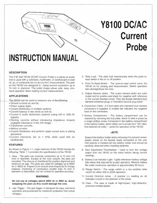
The following measurement techniques are provided as guidelines to be followed when using the Y8100. Included are procedures for measuring ac, dc, composite (ac on dc) currents, safety hints, and measurement notes. These procedures should be read carefully before using the Y81 00.
5. Output Banana Jacks - The output banana jacks are color coded red for positive and black for negative with reference to the current direction arrow. They will accept standard dual mi.n-anaconnector-plugs o-rTridividuaT banana plugleacrs.-- ·
3. Slide Lock - The slide lock mechanically locks the push-to read switch in the on or off position.
4. Push-To-Read-Switch - The push-to-read switch turr)s the Y81QQ on for zeroing and measurement. Switch operation also demagnetizes the core.
CN8100系列温度控制器说明书

U L arge, Easy-to-Read LED, Selectable for EitherSetpoint or ProcessTemperatureU T ype J or KThermocouple InputU A djustable O utputHysteresis to PreventRapid Cycling AroundSetpoint TemperatureU A djustable Deviation Alarm Flashes When MeasuredTemperature Exceedsor Falls Below SetpointTemperatureU N EMA 4X (IP65) FrontBezel, Splash-Proof andResistant to DustU D iscrete Status Indicators Illuminate WhenTemperature Display,Setpoint Display or Heat/Cool Output Is ActiveU A uto Tuning (CN8101and CN8102)CN8100 SeriesThe CN8100 Series controller is alow-cost, general purpose 1⁄4 DINtemperature controller, ideal for OEM or replacement applications. Microprocessor-based and accurate to ±0.3% FS, it may be orderedas either a PID controller, on/off controller or limit safety device.As a separate safety feature to your control application, the CN8121-R1 limit controller provides reliable high/ low temperature limit shut-off control for most machine and process control applications including environmental chambers, furnaces, SpecificationsGeneralLine Voltage: 85 to 250 Vac, 50/60 Hz,120 to 300 Vdc (auto polarity)Display: 3-digit, 14 mm (0.56")orange LEDDiscrete Indicators:Setpoint: AmberActual: AmberHeat: OrangeCool: OrangeCN8102-R1-R2, dual output PIDcontroller shown smaller thanactual size.Power Consumption:Less than 6 VA (instrument)Front Panel Rating: NEMA 4X (IP65)Operating Temperature:0 to 60°C (32 to 140°F)Humidity Tolerance: 90% RHmaximum, non-condensingMemory Protection:Solid-state, non-volatile memoryConnections: Fast-on style(0.250" wide)Panel Cutout:1⁄4 DIN, 92 mm2 (3.622 in2)Dimensions: 96 x 96 x 6.35 mm bezel(3.78 x 3.78 x 0.25")Panel Depth: 88.9 mm (3.5")Weight: 737 g (1 lb. 10 oz)PerformanceAccuracy: ±0.3% of FS, ±1 digitSetpoint Resolution: 1 countRepeatability: ±1.0 countTemperature Stability:5µV/°C maximumovens and packaging machinery. Asa high-limit device, these controllershave a normally energized SPSTlatching output relay which becomesde-energized whenever the processvariable (PV) exceeds a selectedsetpoint value. Reset of the latchingoutput relay is done by holding theparameter button for 3 seconds onthe front panel of the controller, orby cycling power to the controller.1⁄4 DIN Digital Temperature and Limit ControllersP a n e l p u n c h es a v a i l a b l e* Specify output type from Output Options table.Ordering Examples: CN8102-R1-R2, 1⁄4 DIN dual mechanical relay output PID controller.OCW-3, OMEGACARE SM extends standard 2-year warranty to a total of 5 years.CN8121-R1.Controllers shownsmaller than actual size.CN8102-R1-R2.CN8111-R1.TC Cold End Tracking: ±0.05°C/ °C ambientNoise Rejection: Common mode >100 dB, Series mode >70 dBProcess Sampling: 3.7 Hz (270 ms)Available Inputs: Thermocouple: CN8110: Type J CN8120: Type J CN8100: Type J or K Maximum lead resistance, 100 Ω for rated accuracy Control Characteristics:Control Hysteresis: 1 to 140°C (2 to 252°F)Display Offset: -70 to 70°C (-126 to 126°F)Deviation Alarm: Off, 1 to 140°C (Off, 1 to 252°F)Outputs: Electromechanical relay, 5 A @ 250 Vac, 5 A @ 30 Vdc, solid-state relay, 120/240 Vac, 0 voltage switched, 2 A continuous (output 1), 0.5 A continuous (output 2) 10 A surge @ 25°C (77°F), pulsed DC 5V for external SSROMEGACARE SMextended warranty program is available for models shown on this page. Ask your sales representative for full details when placing an order. OMEGACARE SMcovers parts, labor and equivalent loaners.。
精控AC7100C技术手册
概述
1
第1章 技 术 规 格
2
1 . 1 A / D转 换
2
1.2 显示
2
1.3 一般规范
2
1.3.1 控 制IO口
2
1.3.2 计量功能
3
1.3.3 综合
3
第2章 安 装 与 接 口
4
2.1 安装环境
4
2.2 电源
4
2.3 传感器输出及输入灵敏度
4
2.4 传感器连接
5
2.5 内部 结构
B:秤 斗 内物 料 流动 时 ,可 能 产生 静 电。 C:雷 击 引起 的 大电 流 回流 入 地。 D:电 焊 作业 时 ,焊 机 的零 线 大电 流 通过 传 感器 支 撑点 所以一定要设计如下回流电缆。
回流电缆
4芯传感器 与变送器 接线图 传感器 EXC+
SIG-
SIG+
EXC-
铜丝或铜带纺织: 总 截面 积 ≥1 6 m m 2, 散 流电 阻 ≤5Ω
去皮功能
按 TARE 键 或 者控 制IO指 令 可使 当 前重 量 显示 为 零。 去 皮范 围 :毛 重<满 量程 。
当重量值在每秒内的变化量超过稳定检测范围时,判断为 动态检测功能 不稳定。不稳定状态指示灯亮。
稳 定检 测 范围 :1d/s,3d/s,5d/s,10d/s。
串联连接两级数字滤波器。 数字滤波功能
特别注意
严禁传感器屏蔽线或接线盒到变送器的屏 蔽线 接地,否 则会烧坏 变送器或 传感器!!
6
安装与接口连接
◆ 传 感 器 必 须 可 靠 接 地. A:传 感 器安 装 设备 上 同时 安 装有 频 繁启 动 的大 功 率电 机 ,工 作 时的 外
麦克维尔温控器产品技术手册
产品功能
■ 室内温度设定 ■ 室内温度测量 ■ 单冷/冷暖两管 ■ 高风/中风/低风
技术指标
■ 感温元件:模盒
■ 控温精度:±1℃
■ 外壳材料:ABS(阻燃)
■ 电源电压:220VAC±10%
■ 外形尺寸:130×85×45
■ 接线方式:端子压接
■ 工作环境:0~45℃,5-95%RH (不结露)
接线图
c 2012 McQuay International.All rights reserved. c 2012 麦克维尔国际公司,版权所有。 是麦克维尔在美国和其它国家的注册商标,拥有全世界承认的商标权。事先没有麦克维尔书面同意,为商业用途 而使用上述商标标志,将违反美国联邦、州和相关国家法律,可以被指控为侵犯商标权和进行不公平竞争。 本手册由麦克维尔深圳工厂市场部编制。根据版权法,未经麦克维尔书面同意,任何人不得复制本手册中的全部或部分内 容,或以其他形式散播。 我们已尽力确保本手册上的信息准确。由于我们一直致力于技术改进,因此机组及规格参数如有变动,恕不另行通知。另 外,为适应当地的条件及客户要求,也可能对机组及规格参数做些修改。并需说明,不是所有的机型均适合每个市场。 本手册中介绍的是在中国制造的产品。
型号命名
AC500B
D:配置干节点(干节点:在制冷/制 热模式下,当阀开启时,干节点导 通,当阀关闭时,干节点断开)
11: 单冷节能:温度达到设定值,关 闭电动阀及风机
12: 单冷非节能:温度达到设定值, 关闭电动阀,风机仍按设定风速 运行
21: 热泵节能:温度达到设定值,关 闭电动阀及风机
22: 热泵非节能:温度达到设定值, 关闭电动阀,风机仍按设定风速 运行
ದ็औᒜ औሣछ
013 8100、8200控制屏说明
Logo
8120控制屏说明
主控制器为BE24控制器
科泰电源设备(上海)有限公司
COOLTECH POWER(SHANGHAI)LTD.
Logo
8120控制屏说明
主控制器参量信息
1、低燃油液位报警指示 2、紧急停机报警指示 3、低油压停机报警指示 4、高水温停机报警指示 5、电池电压值 6、皮带断裂/充电发电机故障报警指示 7、超/低频率停机报警指示 8、启动失败停机报警指示 9、交流发电机故障
科泰电源设备(上海)有限公司
COOLTECH POWER(SHANGHAI)LTD.
Logo
8100控制屏说明 8100控制屏(501K) 8100控制屏(501K)电路原理 控制屏
科泰电源设备(上海)有限公司
COOLTECH POWER(SHANGHAI)LTD.
Logo
8120控制屏说明
二、8120控制屏说明 8120控制屏说明
Logo
8100、8120、8200、8220控制屏说明 8100、8120、8200、8220控制屏说明
科泰电源设备(上海)有限公司
—销售服务中心
版本编号:VO.0801-13
Logo
8100、8200控制屏说明 8100、8200控制屏说明 目 录 1、8100控制屏说明 2、8120控制屏说明 3、8200控制屏说明 4、8220控制屏说明 5、KX系列ATS
科泰电源设备(上海)有限公司
COOLTECH POWER(SHANGHAI)LTD.
Logo
8120控制屏说明
控制屏外面板 1.主控制器:整个系统的主控制器; 2.微型空气开关:控制线路过流及短路保护; 3.紧急停机按钮
3
8100+说明书
4.21 输出 1 – 线性直流 .....................................................17
4.22 输出 2 - 继电器 ........................................................17
4.23 输出 2 – 双继电器 .....................................................18
7 操作模式 .................................................................................................................... 23
7.1 选择模式 .............................................................24
5.4 LED 指示灯功能.......................................................22
6 故障显示 .................................................................................................................... 23
4.27 输出 3 - 继电器........................................................19
4.28 输出 3 - SSR 驱动 .....................................................19