车载旋转开关SRBV141201选型手册
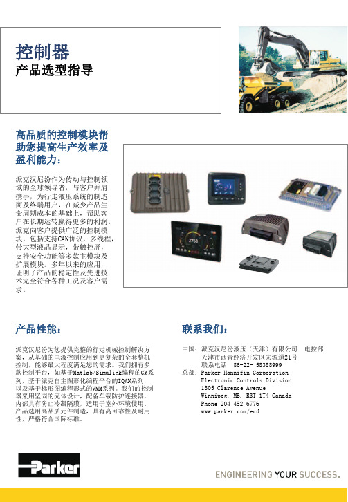
控制器选型指导手册

MD4
主模块(显示器)
9 ~ 32
IP65/IP6K9K SAE J1939 CANopen, IQAN Protocol
4 2 10 (2) (4) -
MC2
主模块
11 ~ 32
IP66/IP6K9K SAE J1939 Generic CAN IQAN Protocol
4
Parker Hannifin Corporation
产品技术信息
技术规范 电磁干扰 ISO 14982:1998,辐射发射; EN 55025:2003,辐射发射; ISO 11452-2:1995,电磁场; ISO 11452-4:2001,射入无线电; ISO 7637-2:1990,电源瞬变; ISO 7637-3:1995,电源瞬变;
技术特性
IQAN-MD3配有3.5英寸半透反射式液晶彩色显 示屏。其5个导航键和4个功能软键,使操作 者更易于交互控制。该模块的设计易于在车 辆仪表板或外部控制面板上安装。具有2个密 封防误插德驰DTM12连接器。
IQAN-MD3的32位微处理器与其它IQANdesign 主模块具有相同的内核,使应用程序功能组 可在不同模块间传输。采样率可最低设置到 10ms。模块具有较大的内存,用于数据记录, 可存储80000条信息。
通信接口 CAN(ISO 11898) -通信协议
RS-232 -通信协议
USB2.0(全速)
3 1) Parker ICP, J1939,通 用协议等 1 AT-Hayes, GSM07.07, GSM07.05,IDP 1
输出 数字输出 -类型 -最大负载
1 高电平开关 200mA
输入 电压输入 -信号范围 -分辨率 数字输入 -高电平 -低电平
S120单轴驱动器选型手册 V1.3

Sinamics S120 AC/AC 驱动器
-1-
西门子(中国)有限公司 自动化与驱动集团 运动控制部
Sinamics S120 系列丛书
S120 AC/AC 产品简易选型手册
第一章 SINAMICS S120 驱动器的概述
Sinamics S120 AC/AC 单轴驱动器是在西门子推出的新一代交流驱动产品-Sinamics S120 的基础上,又新增 加的集整流和逆变于一体的新驱动器,它是集 V/F、矢量和伺服控制功能的高精度、高性能的新型驱动器。它 既能控制普通的三相异步电动机,又能控制同步伺服电机、力矩电机及直线电机。其强大的定位功能将实现进 给轴的绝对、相对定位。 Sinamics S120 产品包括:用于共直流母线的 DC/AC 逆变器和用于单轴的 AC/AC 变频器。
-伺服控制模式 -矢量控制模式 -V/F 控制模式 控制电源 环境温度
1 相. 200 V - 240 V AC ±10% (-15% < 1 分钟) 3 相. 380 V - 480 V AC ±10% (-15% < 1 分钟) 47 Hz - 63 Hz 约 1.35 x 进线电压
0 Hz - 650 Hz 0 Hz - 300 Hz 0 Hz - 300 Hz 24 V DC, -15/+20% 0℃到+40℃
• 单轴控制的 AC/AC 变频器,通常又称为 Sinamics S120 单轴交流驱动器,其结构形式为电源模块和 电机模块集在一起,特别适用于单轴的速度和定位控制。
本书只介绍 Sinamics S120 单轴交流驱动器, 而 Sinamics S120 多轴驱动器,将在另一本书作详细描述。
Sinamics S120 AC/AC 单轴驱动器由两部分组成:控制单元和功率模块
宇通系列客车说明书

ZK6120HT系列客车使用说明书郑州宇通客车股份有限公司2004年6月8日前言尊敬的用户,感谢您使用宇通客车。
郑州宇通客车股份有限公司拥有亚洲最大的客车生产基地、国家博士后科研工作站和国内客车行业国家一级全自动检测线。
雄厚的研发和生产实力确保了宇通客车具有较高的质量水平。
多年来,宇通客车以其卓越的性能赢得了越来越多的用户的青睐。
ZK6120HT系列客车是我公司针对国内客运市场需求而精心设计生产的高档客车,选用德国MAN公司技术生产的LBC6121高档客车专用底盘,质量和性能成熟可靠。
车身设计则充分体现了“以人为本”的设计理念:造型豪华、气派,内饰典雅、大方;车厢内布置简洁、合理,给人明快、舒畅的视觉享受。
在整车制造程中采用了涨拉粘接蒙皮和自动点焊工艺,极大的提高了车身的平整度和密封性;优质的异型钢材和先进的防锈处理工艺确保了车身的骨架强度和防腐性能。
本说明书介绍了整车装备、操纵系统、主要技术参数、使用方法以及使用注意事项,关于底盘方面更详细的说明请见“客车A55/A82/A83/A85型后置发动机客车底盘使用手册”。
若对配套总成的操作要求不太熟悉,请仔细阅读随车提供的相应使用说明书。
尊敬的用户,客车最大性能的发挥很大程度上取决于您对车辆的熟悉和保养维护程度。
我们恳请您在使用客车之前务必对各说明书进行认真的阅读,并严格遵守其中的要求、规定。
为了能给您提供更加优质的服务,我公司设有全国800免费电话,当您在客车使用中遇到问题请及时与我们联系,我们一定会热忱、及时的为您服务。
销售电话:8008836806 服务电话:8008836816欢迎您在使用本说明书的过程中多提宝贵意见和建议。
再次衷心地感谢您承购宇通客车!郑州宇通客车股份有限公司中国·郑州二ΟΟ三年四月1特别声明尊敬的客户,请在使用该车之前仔细阅读本说明书、LBC6121型后置发动机客车底盘使用手册、保养维修手册和配发的其它总成说明书。
汽车自动转向系统维护手册说明书

A low fluid level can indicate a leak in the clutch system. Have this system inspected as soon as possible.
Using any non-Honda brake fluid can cause corrosion and decrease the life of the system. Have the brake system flushed and refilled with Honda Heavy Duty Brake Fluid DOT 3 as soon as possible.
5. If the level is below the lower mark, add fluid into the dipstick tube to bring it to the upper mark.
UPPER MARK LOWER MARK
3. Insert the dipstick all the way back into the transmission securely as shown in the illustration.
BOLT
UNDER COVER
To check the transmission fluid level, remove the two bolts, then pull the left part of the under cover down.
If you are not sure how to add fluid, contact your dealer.
v w
Main Menu
Table of Contents
车载通用型(企标)说明书

正弦波逆变器使用说明书使用安装前请认真阅读本说明书感谢您选用了我公司提供的纯正正弦波车载逆变器,愿我们及我们的产品能为您带来最满意的服务。
一、产品特点此款纯正正弦波逆变器是本公司精心研发的全功能逆变电源;采用高效SPWM脉宽控制技术,其具有:控制精确,输入输出隔离,安全高效,可靠性高等特点。
逆变器将蓄电池的直流电能转换成220V正弦波交流电,本逆变器广泛应用于不同品牌汽车。
本产品具备了相当完善的智能化保护功能,解决了您安全问题上的后顾之忧。
本系列产品已通过国家TS16949质量管理体系认证;并由本公司自主开发研制,采用多项高新技术和智能型驱动芯片,大大减免了分立元件进行控制保护的繁琐性,提高了机器的可靠性,也为您的使用提供方便。
二、技术指标使用条件:环境温度:-20℃—+55℃状态提示:正常工作状态绿色LED亮,过压状态绿色LED亮无输出,欠压状态(可自行恢复)/过热保护状态无输出红色LED亮,过载短路保护状态无输出并报警。
三、保护功能1.过载保护:当您接入的用电器过多,总功率超过逆变器允许负荷的125﹪时,机器将自动在20秒之内停止工作并报警提示,直到您降低了负荷,关闭逆变器5秒钟后重新启动可恢复工作。
2.短路保护:逆变器电源工作过程中如发生负载短路故障,也会自动保护,状态及处理同过负荷保护。
3.温度保护:当您的负荷较多、工作时间较长,或是气候炎热通风不良,逆变器内部的温度会逐步升高,到一定程度后(80℃以上),红色指示灯亮起,逆变器停止工作,并锁定保护状态。
建议您降低负荷,改善通风环境,待内部温度降低后,将逆变器重启可恢复工作。
4.欠压保护:逆变器工作过程中,如果蓄电池电压逐步降低,当低于停机下界点时,红色LED亮起逆变器停止工作,待蓄电池充电电压上升至恢复点时逆变器将自动恢复工作5.过压保护:当输入电压超过安全电压时,输出会被切断逆变器停止工作,待输入电压正常时逆变器将自动进入工作状态。
6.反接保护:当输入连接线接反时,会烧断保险丝,此时应立即关掉逆变电原,待检查无误后,更换与之相同规格的保险丝即可。
AUMA多回转带AM电动执行器操作手册

DIN ISO 9001/ EN 29001
Certificate Registration No. 12 100 4269
多回转电动执行器 SA 07.1 - SA 16.1 / SAR 07.1 - SAR 16.1 AUMA MATIC
3. 接线端子说明 . . . . . . . . . . . . . . . . . . . . . . . . . . . . . . . . . . . . . . . . . . . . . . . 6
4. 存储和运输 . . . . . . . . . . . . . . . . . . . . . . . . . . . . . . . . . . . . . . . . . . . . . . . . . 7
14. 电气位置反馈RWG设定(选项) . . . . . . . . . . . . . . . . . . . . . . . . . . . . . . . . . . . . . . . 16 14.1 两线制4 - 20 mA 和 三/四线制0 - 20 mA设定.. . . . . . . . . . . . . . . . . . . . . . . . . . . . . . 17 14.2 三/四线制4 - 20 mA设定 . . . . . . . . . . . . . . . . . . . . . . . . . . . . . . . . . . . . . . . . 18
10. 力矩开关设定 . . . . . . . . . . . . . . . . . . . . . . . . . . . . . . . . . . . . . . . . . . . . . . . 13
Belimo NVK24A-SZ-TPC 模块化旋转阀控制器说明书
Modulating globe valve actuator for 2-way and3-way globe valves• Actuating force 1000 N• Nominal voltage AC/DC 24 V• Control modulating 0.5...10 V• Stroke 20 mmTechnical dataElectrical data Nominal voltage AC/DC 24 VNominal voltage frequency50/60 HzNominal voltage range AC 19.2...28.8 V / DC 21.6...28.8 VPower consumption in operation 2.5 WPower consumption in rest position 1.5 WPower consumption for wire sizing 6 VAConnection supply / control Terminals with cable 1 m, 4x 0.75 mm²(Terminal 4 mm²)Parallel operation Yes (note the performance data)Functional data Actuating force motor1000 NOperating range Y0.5...10 VInput impedance100 kΩPosition feedback U0.5...10 VPosition feedback U note Max. 0.5 mASetting fail-safe position Stem 0...100%, adjustable (POP rotary knob)Bridging time (PF)2 sPosition accuracy±5%Manual override with push-buttonStroke20 mmRunning time motor150 s / 20 mmRunning time fail-safe35 s / 20 mmAdaptation setting range manual (automatic on first power-up)Sound power level, motor45 dB(A)Sound power level, fail-safe60 dB(A)Position indication Mechanical, 5...20 mm strokeSafety data Protection class IEC/EN III, Safety Extra-Low Voltage (SELV)Power source UL Class 2 SupplyDegree of protection IEC/EN IP54Degree of protection NEMA/UL NEMA 2Enclosure UL Enclosure Type 2EMC CE according to 2014/30/EUCertification IEC/EN IEC/EN 60730-1 and IEC/EN 60730-2-14Safety dataUL ApprovalcULus according to UL60730-1A, UL60730-2-14 and CAN/CSA E60730-1The UL marking on the actuator depends on the production site, the device is UL-compliant in any case Type of actionType 1.AA Rated impulse voltage supply / control 0.8 kV Pollution degree 3Ambient humidity Max. 95% RH, non-condensing Ambient temperature 0...50°C [32...122°F]Storage temperature -40...80°C [-40...176°F]Servicingmaintenance-free Weight Weight 1.4 kgTermsAbbreviationsPOP = Power off position / fail-safe position CPO = Controlled power off / controlled fail-safePF = Power fail delay time / bridging timeTechnical data••••••Safety notesThis device has been designed for use in stationary heating, ventilation and air-conditioning systems and must not be used outside the specified field of application, especially in aircraft or in any other airborne means of transport.Outdoor application: only possible in case that no (sea) water, snow, ice, insolation or aggressive gases interfere directly with the device and that it is ensured that the ambient conditions remain within the thresholds according to the data sheet at any time.Only authorised specialists may carry out installation. All applicable legal or institutional installation regulations must be complied with during installation.The switch for changing the direction of motion and so the closing point may be adjusted only by authorised specialists. The direction of motion is critical, particularly in connection with frost protection circuits.The device may only be opened at the manufacturer's site. It does not contain any parts that can be replaced or repaired by the user.The device contains electrical and electronic components and must not be disposed of as household refuse. All locally valid regulations and requirements must be observed.Product featuresOperating modeThe actuator is connected with a standard control signal of 0...10 V and moves to the position defined by the control signal at the same time as the integrated capacitors are loaded.Interrupting the supply voltage causes the valve to be moved to the selected fail-safe position by means of stored electrical energy.Pre-charging time (start up)The capacitor actuators require a pre-charging time. This time is used for charging thecapacitors up to a usable voltage level. This ensures that, in the event of a power failure, theactuator can move at any time from its current position into the preset fail-safe position. Theduration of the pre-charging time depends mainly on how long the power was interrupted.Typical pre-charging time[d] = Power failure in days[s] = Pre-charging time in secondsDelivery condition (capacitors)The actuator is completely discharged after delivery from the factory, which is why theactuator requires approximately 20 s pre-charging time before initial commissioning in orderto bring the capacitors up to the required voltage level.Setting fail-safe position (POP)The rotary knob fail-safe position can be used to adjust the desired fail-safe position from0...100% in 10% increments. The rotary knob refers to the adapted or programmed height ofstroke. In the event of a power failure, the actuator will move to the selected fail-safe position,taking into account the bridging time (PF) of 2 s set at the factory.Simple direct mounting Simple direct mounting on the globe valve by means of form-fit hollow clamping jaws. Theactuator can be rotated by 360° on the valve neck.Manual override Manual control with push-button possible - temporary. The gear train is disengaged and theactuator decoupled for as long as the button is pressed.The stroke can be adjusted by using a hexagon socket screw key (4 mm), which is insertedinto the top of the actuator. The stroke shaft extends when the key is rotated clockwise.High functional reliability The actuator is overload protected, requires no limit switches and automatically stops whenthe end stop is reached.Home position Factory setting: Actuator stem is retracted.When valve-actuator combinations are shipped, the direction of motion is set in accordancewith the closing point of the valve.The first time the supply voltage is switched on, i.e. at the time of commissioning, the actuatorcarries out an adaptation, which is when the operating range and position feedback adjustthemselves to the mechanical setting range.The actuator then moves into the position defined by the control signal.Adaptation and synchronisation An adaptation can be triggered manually by pressing the "Adaptation" button. Bothmechanical end stops are detected during the adaptation (entire setting range).The actuator then moves into the position defined by the control signal.Setting direction of motion When actuated, the stroke direction switch changes the running direction in normaloperation. The stroke direction switch has no influence on the fail-safe position which hasbeen set.Product featuresAccessoriesElectrical accessories Description TypeAuxiliary switch 2x SPDT add-on S2A-HWire colours:1 = black2 = red3 = white5 = orangeElectrical installationSupply from isolating transformer.Parallel connection of other actuators possible. Observe the performance data.Direction of stroke switch factory setting: Actuator stem retracted (▲). Wiring diagramsAC/DC 24 V, modulating Override control (frost protectioncircuit)Operating controls and indicators1Direction of stroke switchSwitch over:Direction of stroke changes2Cover, POP button3POP button4Scale for manual adjustment6(No function)7Manual override buttonPress button:Gear train disengages, motor stops, manual override possibleRelease button:Gear train engages, standard modeLED displaysyellow 8green 9Meaning / functionOff On Operation OKOff Flashing POP function activeOn Off- Pre-charging time SuperCap- Fault SuperCap- Wiring error in supplyOff Off Not in operationOn On Adaptation process active9Push-button (LED green)Press button:Triggers stroke adaptation, followed by standard mode10Manual overrideClockwise:Actuator stem extendsCounterclockwise:Actuator stem retractsOperating controls and indicatorsSetting fail-safe position (POP)DimensionsFurther documentation• The complete product range for water applications• Data sheets for globe valves• Installation instructions for actuators and/or globe valves• Notes for project planning 2-way and 3-way globe valves• General notes for project planning。
波导旋转接头产品手册说明书
Waveguide rotary joints are mainly used for signal transmission between the fixed part and the rotating part. The terminal of the waveguide rotating joint involve coaxial, rectangular waveguides and ridge waveguides. There are single-channel and multi-channel waveguide rotary joints. According to the structure, it is divided into I type, L type and U type.Waveguide Rotary JointsSMABJ140(WR62)Fixed PartRotating PartBJ320(WR28)WaveguideFixed PartRotating PartBJ320(WR28)WaveguideWRD650WRD650Fixed PartRotating PartHigh Performance Flexible Waveguide Cable AssemblyThe high performance flexible waveguide cable assembly combines the advantages of waveguide and RF coaxial cable, which can be used in applications where the space is small, the weight is light, and the two ports are complex. It has the characteristics of flexible installation, small size, light weight, small footprint, small bending radius, small VSWR, low insertion loss and excellent phase consistency. It is suitable for microwave signal transmission in space areas such as airborne, missile, and spaceborne. There are rectangular type and ● Waveguide Range: BJ70(WR137) ~ BJ400(WR22)● Frequency Range : 6GHz to 50GHz ● VSWR ≤ 1.25 (20% waveguide bandwidth)● VSWR ≤ 1.3 (40% waveguide bandwidth)ridge waveguide port.According to the frequency and power capability requirements, select the corresponding waveguide port and RF coaxial cable. Typical features are as follows:Typical Flexible Waveguide Cable Assembly● Note: The actual power resistance data is related to the ambient temperatureand air pressure value.pressure environments.Typical features are as follows: ● Power Capability:X-band average power up to 900W Ku band resistance is up to 500W Ka band resistance up to 340WThe high power, high performance flexible waveguide cable assembly is a commonly used microwave component in high power microwave port input and output devices. It covers the X, Ku, K, and Ka bands. It has the advantages of frequency bandwidth, small VSWR, low insertion loss and high power consumption. It is used to connect the same (or different) waveguide microwave circuits in a small, complex space to transmit high-power microwave signals. It also has excellent high frequency performance in lowWaveguide 1:BB125-F Waveguide 2:BB125A-E Typical High power Waveguide Assembly210W average power,40% duty cycle,5 min durationZBD104E-BJ140E /BJ140E-50015.799mm ×7.899mm Waveguide Size SUCOFLEX104E;MF607ACable Type14GHz ~18GHz Frequency Power Capability VSWR ≤1.25ZBD104E-BJ220E/BJ220E-50010.668mm ×4.318mm 190W average power,40% duty cycle,5min durationWaveguide Size SUCOFLEX104E;MF607ACable Type20GHz ~24GHzFrequency Power Capability VSWR ≤1.2570W average power,45% duty cycle,5min duration Waveguide Size Cable Type32GHz ~38GHzFrequency Power Capability VSWR ≤1.3ZBD102E-BJ320E/BJ320E-5007.112mm ×3.556mm SUCOFLEX102E;MF419AThe company establishes the waveguide cable assembly type spectrum platform, which involves the waveguide ports BJ140(WR62), BJ220(WR42) and BJ320(WR28). High-power microwave signals are transmitted using a frequency range of 14 GHz to 18 GHz, 20 GHz to 24 GHz, and 32 GHz to 38 GHz.The spectral waveguide cable assembly is mainly used to transmit the high-power signal of the transmitter output with high performance and low loss to the antenna feeder system.High Performance Flexible Waveguide Cable AssemblyHigh Power Waveguide Cable assembly in Typical Low Pressure EnvironmentHigh Performance Flexible Waveguide Cable AssemblyThe frequency of wave-guide to coax adapters processed byELT cover 5.4GHz-70GHz. With high reliability, small size andexcellent performance, it is widely used in microwavemeasurement and millimeter wave equipment. The waveguidehas standard rectangular and double-ridge waveguides, andnon-standard waveguides can be customized according to userrequirements. The coaxial end connection interface includes N,TNC, SMA, SMP, 3.5, K (2.92), 2.4, 1.85 and microstrip. Wave-guide to coax adapters are divided into two types: end Launchand right angle launch from interface orientation. Among them,the RA launch type can also be used as a high-power structure.Wave-guide to Coax AdaptersTypical mmW Coaxial to Rectangular Waveguide AdapterTypical Coaxial Ridge Waveguide AdapterWave-guide to Coax AdaptersFeaturesKa band 6GHz bandwidth Frequency 7.112mm ×3.556mm Insertion Loss ≤1.4VSWR≤0.4dBWaveguide Size Typical Hermetic Coaxial Microstrip to Waveguide AdapterBJ320(M )×2-FD1The hermetic coaxial microstrip to waveguide converter is primarily used for hermetic connections between different systems. The coaxial end is usually a glass sintered part, and the waveguide is reliably connected by welding. This type of product has high welding reliability, good assembly dimensional consistency, high frequency bandwidth and excellent performance.BB320A(M)-FD1Double waveguide port; hermetic coaxial end, microstrip diameter Φ0.3mmVery small waveguide size, the total height of the waveguide can be extended to 25mm;FeaturesKa band 6GHz bandwidth Frequency 7.11mm ×1.78mm Insertion Loss ≤1.45VSWR≤0.5dBWaveguide Size Hermetic coaxial end, microstrip diameter Φ0.3mmBG435A (M )-FD1B FeaturesKa band 6GHz bandwidth Frequency 5.2mm ×2.85mm Insertion Loss≤1.4VSWR ≤0.5dBWaveguide Size Hermetic coaxial end, microstrip diameter Φ0.3mm BG435A (M )-FD1Features Ka band 6GHz bandwidth Frequency 5.2mm ×2.85mm Insertion Loss≤1.35VSWR ≤0.4dBWaveguide Size Hermetic coaxial end, microstrip diameter Φ0.3mmThe microstrip output is offset from the waveguidecenter output by 2.7mmHigh Temperature Resistant Waveguide ComponentsThe high temperature resistant waveguide component is a new type of component that ensures the normal transmission of microwave signals in a high temperature environment.Divided into high temperature type and high temperature resistant type. The former can transmit microwave signals in a high temperature (+400 ° C) environment, the latter can be used in high temperature environment, or can also isolate high temperature conduction (temperature difference 400 ° C → 80 ° C), can protect the transmission system from high temperature damage. The frequency covers 5.4 GHz to 50 GHz and is suitable for each waveguide port of BJ70(WR137) to BJ400(WR22).High temperature resistant insulated conversion waveguide Laser welding type heat insulation conversion waveguideWave-guide to Coax AdaptersWaveguide Sealing WindowThe waveguide sealing window is a waveguide device that connects two waveguide ports for sealing. The frequency covers 6.5 GHz to 60 GHz. The waveguide has standard rectangular and double ridge waveguides, and non-standard waveguides can be customized according to user requirements. The products have excellent performance and high reliability, and are widely used in communication systems, radar systems and high-power waveguide transmission systems. The waveguide sealing window also has a thermal insulation function.。
施耐德宝光VS1 Pro-12X系列户内高压真空断路器产品选型手册说明书
Schneider Baoguang关于施耐德宝光施耐德(陕西)宝光电器有限公司(简称SSBEA或施耐德宝光)是施耐德电气专业从事中、系统及相关产品研发、生产和销售的中外合资企业。
高新科技园区。
在世界五百强企业与中国中压电器龙头企业的通力合作下,作为国内中压行业著名的“宝光”品牌真空断路器的唯一合法生产商,施耐德宝光秉承精益生产科学理念,凭借品质过硬、安全可靠的全系列高品质产品和覆盖用户全生命周期的完善服务,帮助用户实现卓越的生产运营绩效和市场竞争力,用品质的“不妥协”实现可持续发展之道。
我们致力于将施耐德宝光打造成为中国卓越和高效的中压断路器和系统的制造平台,依托自身的专业优势,为广大用户和合作伙伴提供领先的总成本和长期全面的安心保障。
目 录概述VS1 Pro-12X 型户内高压真空断路器(以下简称断路器)是额定电压12kV 及以下、交流50Hz 的户内开关设备元件。
断路器与KYN28A-12型开关柜配套使用,也可安装于XGN2等固定式开关柜内。
产品符合GB 1984《高压交流断路器》、GB/T 11022 《高压开关设备和控制设备标准的共用技术要求》、JB/T 3855《高压交流真空断路器》、DL/T 403《12kV~40.5kV 高压真空断路器订货技术条件》等标准的规定。
断路器采用弹簧操动机构,可以用交、直流电源储能,也可用手动储能。
具有体积小、开断能力强、绝缘强度高、无污染、无爆炸危险等优点。
产品无论在配电系统正常条件下还是故障条件下(特别是在短路条件下)均可对配电设施提供控制及保护,在额定参数下,可频繁操作,并可多次开断短路电流。
断路器既可用于固定安装单元,也可配用专用推进机构,组成手车单元使用。
可完全替代常规VS1产品。
使用环境产品简介产品概述 ................................................................................. 1 使用环境 ................................................................................. 1 产品优势 ................................................................................. 2技术参数 (4)安装说明断路器外形及安装尺寸 ............................................................... 6二次接线原理图 ........................................................................ 12订货须知 (14)产品真伪查询产品真伪查询 (15)产品概述产品概述■整体设计获得国家专利证书■绝缘筒使用新型环氧树脂材料,APG 工艺,具有高耐压、高强度、爬电距离大等特点 ■独特加强筋设计配用新型控制单元,带有三次强制分闸功能:断路器分闸时,若出现卡滞或线圈出力特性变差,不能实现一次分闸,同时分闸命令未撤销,断路器内部控制单元会让分闸线圈在一定时间内再动作2次,总共分闸动作3次实现强制分闸。
北京现代 MIstra新名图 车主手册说明书
车主手册操作 保养 规格截止出版前,车辆的所有资料都包含在本车主手册里。
由于产品质量的不断提高及相关政策的不断改善,北京现代汽车有限公司有权随时更新资料。
本手册包括了北京现代车型及标准装备和选装件的解释和说明,因此您可能会发现您所拥有的北京现代车辆可能未装备本手册中的某些装备。
All information in this Owner's Manual is current at the time of publication. However, Beijing Hyundai reserves the right to make changes at any time so that our policy of continual product improvement may be carried out. This manual applies to all Beijing Hyundai models and includes descriptions and explanations of optional as well as standard equipment. As a result, you may fi nd material in this manual that does not apply to your specifi c vehi-cle. 본 취급 설명서는 귀하의 차를 보다 안전하고 쾌적하게 운전할 수 있도록 올바른 취급 방법을 설명하였습니다.본 책자에 수록된 사양 및 제원은 폐사 설계 변동에 따라 사전 통고 없이 변경될 수도 있으므로 양지하시기 바랍니다본 취급 설명서엔 각 차종의 기본사양과 옵션사양에 대한 설명이 들어있기에 고객의 차량에 없는 부품들을 소개할 수도 있습니다우측운전(RHD)차량의 조작 방식 설명은 본 취급설명서와 상이할 수 있으니 양지하시기 바랍니다.F2F3前 言感谢您选择北京现代车辆。
- 1、下载文档前请自行甄别文档内容的完整性,平台不提供额外的编辑、内容补充、找答案等附加服务。
- 2、"仅部分预览"的文档,不可在线预览部分如存在完整性等问题,可反馈申请退款(可完整预览的文档不适用该条件!)。
- 3、如文档侵犯您的权益,请联系客服反馈,我们会尽快为您处理(人工客服工作时间:9:00-18:30)。
电路数1
接点数4
切换⾓度30±3°
切换时限Non shorting
旋转扭矩30±15mN·m
操作部形状Flat
操作部长度L: 20mm
使⽤温度范围-10℃ to +85℃
最⼤额定/最⼩额定(电阻负载)0.3A 16V DC/50µA 3V DC
电性能接触电阻(初期/寿命后)50mΩ max./150mΩ max.
绝缘电阻100MΩ min. 100V DC
耐电压100V AC for 1 minute
机械性能端⼦强度5N for 1 minute
操作部强度旋转⽅向0.6N·m
推进⽅向100N
操作部的摆动(轴尖端的负载: 1N)⾃安装⾯的测量位置15mm
轴的振动幅度(最⼤
值)
0.3mm max.
适⽤安装尺⼨20mm
耐久性能⽆负载寿命10,000 cycles 100mΩ max.
负载寿命(最⼤额定负载)10,000 cycles 150mΩ max.
耐环境性能耐寒性能-20±2℃ for 96h
耐热性能85±2℃ for 96h
耐湿性能40±2℃, 90 to 95%RH for 96h
8接点对应竖型 SRBV系列
最⼩订货单位(pcs.)⽇本165
出⼝330
外形图
安装孔尺⼨图
⾃A⽅向看。
操作部详图a
电路图及虚拟端⼦
包装规格
散装
包装数(pcs.)1箱/⽇本165
1箱/出⼝包装330
出⼝包装箱尺⼨(mm)400×270×185
附属零部件
各产品附加的零部件。
焊接条件
浸焊⽅式的参考举例
项⽬预热温度-
预热温度时间-
浸焊焊接温度260±5℃
焊接浸渍时间10±1s
⼿⼯焊接⽅式的参考举例
焊接温度350±10℃
焊接时间3+1/0s
表⽰本系列共通的注释。
1. 本产品⽬录中产品的颜⾊,与实物的颜⾊有所差异。
2. 请以最⼩订购单位的N(整数)倍来订货。
3. 还有上述产品⼀览以外的产品,需要时,请向本公司营业部门询问。
4. 本系列产品也可以⽤于车载。
的使⽤温度范围设定虽然⽐通常的⼤,但是请在使⽤时仔细确认正式的技术规格书。
