使用吉时利4200SCS系统进行太阳能电池IVCV测试
太阳能电池和组件的iv测量仪技术原理
太阳能电池和组件的iv测量仪技术原理太阳能电池和组件的IV测量仪技术原理,听起来好像很高大上,其实咱们老百姓也能听懂。
简单来说,这个仪器就是用来检测太阳能电池和组件的好坏的。
那它是怎么做到的呢?咱们一步一步来分析。
咱们要了解什么是IV测量仪。
IV是In-Vent-Out的缩写,也就是说,这个仪器是用来检测太阳能电池板内部电流流动的方向和大小的。
有了这个信息,我们就能知道太阳能电池板的哪个部分出了问题,从而进行维修或者更换。
接下来,咱们来看看IV测量仪的工作原理。
其实很简单,就是通过一个磁场来控制电流的流动方向。
具体来说,IV测量仪里面有一个线圈和一个磁铁,当电流通过线圈时,会产生一个磁场,这个磁场会和磁铁产生作用,从而改变电流的流动方向。
这样一来,我们就可以通过观察电流的流动方向来判断太阳能电池板的好坏了。
那么,IV测量仪有什么用处呢?它可以帮助我们检测太阳能电池板的性能是否达标。
太阳能电池板的主要功能就是把太阳光转换成电能,如果它的性能不好,就会导致发电效率低下。
通过使用IV测量仪,我们可以及时发现这个问题,从而采取相应的措施进行修复。
IV测量仪还可以帮助我们检测太阳能电池板的故障。
太阳能电池板在使用过程中难免会出现一些小问题,比如某个部位的连接松动、某个元件损坏等等。
通过使用IV 测量仪,我们可以快速找到这些问题所在的位置,从而进行维修或者更换。
IV测量仪还可以帮助我们提高太阳能电池板的使用寿命。
太阳能电池板是一种比较容易老化的设备,如果我们能够及时发现并修复它的小问题,就可以延长它的使用寿命。
而且,通过定期使用IV测量仪对太阳能电池板进行检查和维护,还可以避免一些潜在的问题发生。
IV测量仪是一个非常重要的工具,它可以帮助我们更好地了解太阳能电池板的工作状态,从而提高其性能和使用寿命。
虽然这个名字有点高大上,但是它的原理其实很简单易懂。
希望大家都能了解并掌握这个技能哦!。
太阳能电池IV特性测试仪
太阳能电池IV特性测试仪技术规范书1 太阳能电池IV特性测试仪总则1.1本规范书适用于光伏发电站并网验收、风电场接入并网验收、光伏逆变器型式试验、风力发电机组的低电压穿越检测平台,包括主要设备及其辅助设备的功能设计、结构、性能、安装和试验等方面的技术要求。
1.2要求该检测平台能够同时满足现场安装在风电场的单台风电机组低电压穿越能力检测,满足光伏发电站并网接入验收的低电压穿越能力检测,满足光伏逆变器与风电发电机组的型式试验的低电压穿越试验检测。
1.3本规范书所提出的是最低限度的技术要求,并未对一切技术细节做出规定,也未充分引述有关标准和规范的条文。
供方应保证提供符合本规范书和工业标准的优质产品。
2 太阳能电池IV特性测试仪使用条件2.1环境条件a) 户外环境温度要求:-40℃~ 50℃;b) 户外环境湿度要求:0~90% ;c) 海拔高度:0~2000米(如果超过2000米,需要提前说明)。
2.2安装方式:标准海运集装箱内固定式安装。
2.3储存条件a)环境温度-50℃~50℃;b)相对湿度0~95% 。
2.4工作条件a) 环境温度-40 ºC~40ºC;b) 相对湿度10%~90%,无凝露。
2.5电力系统条件a) 电网电压最高额定值为35kV,电压运行范围为31.5kV~40.5kV;同时也可以同时满足10kV\20kV电网电压的试验检测。
b) 电网频率允许范围:48~52Hz;c) 电网三相电压不平衡度:<= 4%;d) 电网电压总谐波畸变率:<= 5%。
2.6负载条件负载包括直驱或双馈式等风力发电机组,其总容量不大于6.0MVA。
其控制和操作需要满足国家关于风电机组电电压穿越测试与光伏发电站的相关测试规程技术要求。
本检测平台能够同时满足同等条件下光伏电站或光伏逆变器的低电压穿越能力测试。
2.7接地电阻:<=5Ω。
3 太阳能电池IV特性测试仪的技术要求3.1 结构及原理要求根据模拟实际电网短路故障的要求,测试系统须采用阻抗分压方式,原理如下图1所示(以实际为准)。
太阳能电池IV特性实验报告
一、太阳能电池基本IV特性实验1.实验目的1.了解太阳能光伏电池的基本特性参数:开路电压、短路电流、峰值电压、峰值电流、峰值功率、填充因子及转换效率2.了解太阳能光伏电池的伏安特性及曲线绘制3.掌握电池特性的测试与计算2.实验设备光伏太阳能电池特性实验箱。
3.实验原理(1)开路电压Uoc开路电压(Open circuit voltage VOC),当将太阳能电池的正负极不接负载、使电流i=0时,此时太阳能电池正负极间的电压就是开路电压,开路电压的单位是伏特(V)。
单片太阳能电池的开路电压不随电池片面积的增减而变化,一般为0.5~0.7V。
(2)短路电流Isc短路电流(short-circuit current),当将太阳能电池的正负极短路、使电压u=0时,此时的电流就是电池片的短路电流,短路电流的单位是安培(A),短路电流随着光强的变化而变化。
(3)峰值电压Um峰值电压也叫最大工作电压或最佳工作电压。
峰值电压是指太阳能电池片输出最大功率时的工作电压,峰值电压的单位是v。
峰值电压不随电池片面积的增减而变化,一般为0.45~0.5v,典型值为0.48v。
(4)峰值电流Im峰值电流也叫最大工作电流或最佳工作电流。
峰值电流是指太阳能电池片输出最大功率时的工作电流,峰值电流的单位是安培(A)。
(5)峰值功率Pm峰值功率也叫最大输出功率或最佳输出功率。
峰值功率是指太阳能电池片正常工作或测试条件下的最大输出功率,也就是峰值电流与峰值电压的乘积:Pm=Im×Um。
峰值功率的单位是w(瓦)。
太阳能电池的峰值功率取决于太阳辐照度、太阳光谱分布和电池片的工作温度,因此太阳能电池的测量要在标准条件下进行,测量标准为欧洲委员会的101号标准,其条件是:辐照度l000W/m2、光谱AMl.5、测试温度25±1℃。
(6)填充因子FF填充因子也叫曲线因子,是指太阳能电池的最大输出功率与开路电压和短路电流乘积的比值。
太阳电池组件IV特性曲线测试
• 实际上,这两个愿望都是无法实现的,即使完全同材料同工艺制造的太阳电池 的光谱响应也不可能完全相同。
• 然而,进行光谱修正是一个复杂的过程,在实际生产中几乎不被采用。由此, 就引入了光谱失配的误差。
• 同时,测量系统,在组件的测量过程中是指对组件的电压值、电流值、 组件温度和对参考太阳电池的短路电流值进行测量的设备,也存在系 统误差。这个误差是大家最容易理解,也是光能量传递过程中所引入 的各个误差项中最简单的,就是数据采集系统的误差。比如,12位数 据采集器的满量程误差≤±0.04%,参考电池和被测量组件的负载电 阻的误差都为±0.5%,则在满量程条件下短路电流测量值的测量系统 误差应该有: δ≤2×((0.04%)2+(0.5%)2)1/2 = ±1.004%
电子负载
• 图3给出了电子负载的原 理图。其中:E1和E2是两 个直流电源,并且E1的电 压必须大于所测量太阳电 池的开路电压;Rh是一个 可变电阻;Rp是一个精密 电阻,或者被称为负载电 阻。当从下向上滑动可变 电阻Rh,使得被测量的太 阳电池从反向偏置状态向 正向偏置状态变化,太阳 电池逐渐从短路状态向开 路状态变化,从而对太阳 电池的I-V特性进行扫描。
• 测量系统的误差依赖于数据采集器的位数。通常组件测量系统使用并行4通道12位 分辨率数据采集器,理论上可以达到的满量程系统误差小于±0.025%。所以测量系 统误差从来都不是组件测量误差的主要来源。
• 测量系统应该是经过标定的,就是在标准条件下使用不同量值的标准电位计校准测 量系统测量电压量的准确度,使得测量系统无论是在满量程条件还是在其它量程下, 测量值与标准电位计的标定值之间的标准偏差小于给定值,并且生产商应该给使用 者提供这样的标定报告。组件生产商在测量组件的过程中可以仅通过对光源的辐照 度进行标定,也就是通过获得标准组件短路电流,就完成了对组件测量系统的设定。 不幸的是,我们目前使用的测量系统,大多数是没有经过标定的。没有经过标定的 测量系统,就需要在测量组件的过程中对组件的开路电压和短路电流都进行修正, 也就是所谓的功率“校准”的方法。
纳米器件电流-电压(I-V)特性测试
纳米器件电流-电压(I-V)特性测试对于纳米电子和半导体材料与薄膜,采用灵敏的电气测量工具是十分必要的。
它们提供的数据能够帮助我们完全掌握新材料的电气特性和新器件与元件的电气性能。
纳米测量仪器的灵敏度必须要高得多,因为需要测量的电流和电压更低,而且很多纳米材料还明显表现出改善的特性,例如超导性。
待测电流的幅值可能处于飞安量级,电压处于纳伏量级,电阻低至微欧量级。
因此,测量技术和仪器必须尽可能地减少噪声和其他误差源,以免干扰信号。
具有0.1fA(即100 埃安)和1μV 分辨率的吉时利4200-SCS 半导体特征分析系统就是这样一种解决方案。
其专门提供的脉冲I-V 工具套件为脉冲I-V 测量提供了双通道脉冲发生与测量功能。
如果结合内部安装的高速脉冲发生器和示波器,4200 及其PIV 工具套件能够同时实现直流和脉冲I-V 测试。
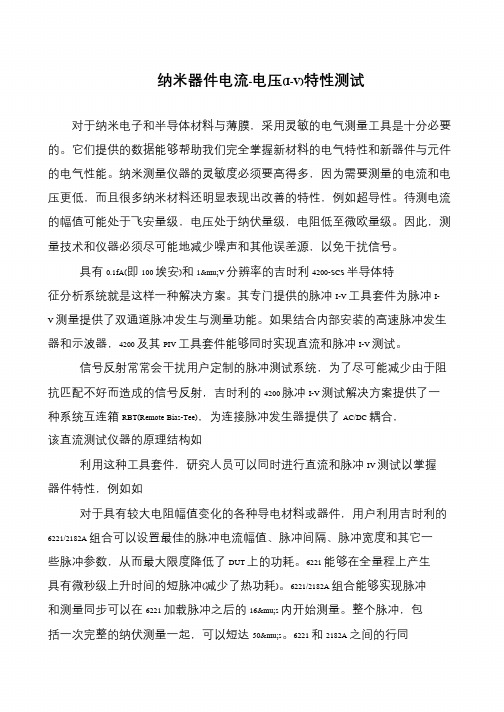
信号反射常常会干扰用户定制的脉冲测试系统,为了尽可能减少由于阻抗匹配不好而造成的信号反射,吉时利的4200 脉冲I-V 测试解决方案提供了一种系统互连箱RBT(Remote Bias-Tee),为连接脉冲发生器提供了AC/DC 耦合,该直流测试仪器的原理结构如利用这种工具套件,研究人员可以同时进行直流和脉冲IV 测试以掌握器件特性,例如如对于具有较大电阻幅值变化的各种导电材料或器件,用户利用吉时利的6221/2182A 组合可以设置最佳的脉冲电流幅值、脉冲间隔、脉冲宽度和其它一些脉冲参数,从而最大限度降低了DUT 上的功耗。
6221 能够在全量程上产生具有微秒级上升时间的短脉冲(减少了热功耗)。
6221/2182A 组合能够实现脉冲和测量同步可以在6221 加载脉冲之后的16μs 内开始测量。
整个脉冲,包括一次完整的纳伏测量一起,可以短达50μs。
6221 和2182A 之间的行同。
光伏iv曲线检测作用

光伏iv曲线检测作用
光伏IV曲线检测是太阳能光伏系统中的重要工具,它具有多方
面的作用。
首先,光伏IV曲线检测可以用于评估太阳能电池的性能。
通过
测量电流-电压(IV)曲线,可以确定太阳能电池的最大功率点(MPP),短路电流(Isc)、开路电压(Voc)、填充因子(FF)等
关键参数,从而评估太阳能电池的性能表现。
这有助于生产商和用
户了解电池的质量和性能,以便进行合适的安装和维护。
其次,光伏IV曲线检测可以用于故障诊断。
通过对IV曲线的
分析,可以检测太阳能电池组件中的短路、开路、电池老化、堵塞、接触不良等问题。
这有助于及时发现和解决电池组件的故障,确保
系统的正常运行。
此外,光伏IV曲线检测还可以用于优化太阳能系统的设计和运行。
通过对太阳能电池的IV曲线进行测量和分析,可以帮助工程师
优化太阳能系统的组件选择、布局设计和工作参数设定,以提高系
统的整体性能和效率。
总的来说,光伏IV曲线检测在评估太阳能电池性能、故障诊断和系统优化方面发挥着重要作用,有助于确保太阳能系统的稳定运行和最大化能源利用。
太阳能电池I-V特性测试实验
摘要随着各国对环境保护的力度加大,再生清洁能源的市场需求巨大,发展太阳能利用技术前景广阔。
太阳能利用领域众多,目前主要通过太阳能电池片把太阳能转换为电能加以利用。
太阳能电池的材料都是半导体材料,电池能量转换的基础是光生伏特(光电)效应。
本文正是基于此对太阳能电池的技术原理进行了深入的研究,并在已有的研究基础上对其电流电压间的关系进行了客观的分析。
首先,阐述了半导体材料的内光电效应,介绍太阳能电池的能量转换过程,包括太阳能电池工作原理、光电转换特性、参数表征。
然后介绍各类电池的技术原理、电池结构与发展前景。
涉及硅太阳能电池,非晶系硅太阳能电池,薄膜太阳能电池等。
最后运用一系列的实验仪器分别测量暗环境和光照条件下硅电池的电流和电压,并作出相应的图像,分析开路电压,短路电流,输出功率变化特点。
进而分析出使太阳能电池的输出功率较大的条件。
关键词:太阳能电池;光电效应;半导体;输出功率AbstractWith the protection of the environment to increase renewable clean energy, the huge market demand, the development of solar energy utilization technology prospect.The solar energy utilization field many, mainly through the film solar cells convert solar energy into electric energy and make use of.Solar cell material is a semiconductor material, battery energy conversion is the basis of photovoltaic (PV) effect.This article is based on the principle of solar cell technology is studied, and on the basis of the study on the relationship between current and voltage in the objective analysis.First, elaborated the semiconductor material within the photoelectric effect, the solar energy conversion process, including the working principle of solar cells, the photoelectric conversion characteristic, parameter characterization.And then introduces the various types of battery technology, battery structure and development prospect.Relates to silicon solar cell, amorphous silicon solar cell, thin film solar cell.Finally, using a series of experimental apparatus were measured in dark environment and under light silicon battery current and voltage, and make the corresponding image analysis, open-circuit voltage, short-circuit current, power output change characteristic.Further analysis to the power output of the solar cell larger conditions.Keywords: Solar cells;Semiconductor;Photoelectric effect;Output power目录第1章绪论 (1)1.1 课题背景 (1)1.2 国内外太阳能发电产业发展现状及趋势 (1)1.3 太阳电池的应用的主要领域 (3)1.4本文主要内容 (4)第2章太阳电池工作原理和特性 (5)2.1 半导体的内光电效应 (5)2.2 太阳电池的能量转换过程 (5)2.3 太阳电池的基本参数 (7)2.3.1 短路电流 (7)2.3.2 开路电压 (9)2.4 太阳电池的输出特性 (10)2.4.1 等效电路 (10)2.4.2 输出特性 (11)2.4.3 转换效率 (12)2.4.4 太阳电池的光谱响应 (12)2.4.5 太阳电池的温度效应 (13)2.4.6 太阳电池的辐照效应 (13)第3章太阳能电池的种类 (14)3.1 硅太阳能电池 (14)3.2 非晶系硅太阳能电池 (14)3.3多元化合物太阳电池 (16)3.3.1 铜铟镓二硒太阳能电池 (16)3.3.2 硫化镉太阳电池 (17)3.3.3 镉碲薄膜太阳能电池 (17)3.3.4 砷化镓太阳电池 (19)3.4 硅薄膜太阳能电池 (19)3.5 染料敏化太阳能电池 (19)第4章太阳能电池I-V特性测试实验 (22)4.1实验原理 (22)4.1.1 太阳能电池无光照情况下的电流电压关系-(暗特性) (22)4.1.2 太阳能电池光照情况下的电流电压关系-(光特性) (23)4.1.3 太阳能电池的效率 (24)4.2实验仪器 (25)4.2.1 光源与太阳能电池部分 (25)4.2.2 光路部分 (27)4.2.3 温度控制及外电路电源 (27)4.3 实验步骤 (29)4.3.1 太阳能电池暗特性测试 (29)4.3.2 太阳能电池光照特性测试 (29)4.4 试验结果 (30)4.4.1 无光照情况下的电流电压关系 (30)4.4.2 光照情况下的电流电压关系 (32)第5章总结 (38)致谢 (39)参考文献 (40)附录A 英文原文 (42)附录B 中文翻译 (49)第1章绪论1.1课题背景随着工业的快速发展和社会经济规模的扩大,人类对能源的需求量与日俱增。
iv曲线测试条件
iv曲线测试条件IV曲线测试是评估太阳能电池性能的重要手段,为了确保测试结果的准确性和可比较性,必须在标准的测试条件下进行。
以下将详细介绍IV曲线测试的主要条件及其重要性。
1.光照强度:光照强度是影响太阳能电池性能的关键因素之一。
为了获得准确的IV曲线,测试必须在恒定的光照强度下进行。
通常,这个光照强度被设定为1000瓦/平方米,即所谓的“标准测试条件”。
这是因为太阳能电池的转换效率与光照强度直接相关,只有在相同的光照强度下进行比较,才能确保结果的准确性。
2.光谱分布:除了光照强度外,光谱分布也是影响太阳能电池性能的重要因素。
太阳光的光谱分布是不均匀的,不同波长的光具有不同的能量。
为了确保测试的一致性,IV曲线测试必须使用标准的光谱分布,通常采用的是AM1.5G光谱。
这种光谱分布模拟了太阳在晴朗天空中的平均光谱分布,是评估太阳能电池性能的常用标准。
3.温度:温度对太阳能电池的性能也有显著影响。
随着温度的升高,太阳能电池的开路电压和短路电流都会发生变化。
为了消除温度对测试结果的影响,IV曲线测试必须在恒定的温度下进行。
通常,这个温度被设定为25摄氏度。
此外,为了确保温度的稳定性,测试过程中还需要对太阳能电池进行适当的冷却。
4.大气质量:大气质量是指太阳光穿过大气层时所受到的散射和吸收程度。
不同的大气质量会导致太阳光的强度和光谱分布发生变化,从而影响太阳能电池的性能。
为了获得可比较的IV曲线测试结果,必须在相同的大气质量下进行测试。
通常,大气质量被表示为AM(Air Mass)值,其中AM1.5是最常用的标准。
5.测试设备的精度和校准:进行IV曲线测试的设备必须具有较高的精度和可靠性。
例如,电流和电压的测量误差必须在允许范围内。
此外,为了确保测试结果的准确性,设备还需要定期进行校准和维护。
综上所述,为了确保IV曲线测试结果的准确性和可比较性,必须在严格控制的条件下进行测试。
这些条件包括恒定的光照强度、标准的光谱分布、恒定的温度、相同的大气质量以及高精度的测试设备。
4200A-CVIV多开关使测试时间缩短30倍
4200A-CVIV多开关使测试时间缩短30倍泰克科技【期刊名称】《中国电子商情·基础电子》【年(卷),期】2017(000)007【总页数】2页(P42,44)【作者】泰克科技【作者单位】【正文语种】中文把各种测量集成到器件特性分析中最困难的问题之一,是每种测量类型基本上都要求不同的线缆。
选择与测量类型配套的线缆增强了测量完整性。
但是,改变每种测量类型的电缆耗时很长,许多用户只能接受次优结果。
此外,在重新连接电缆时,用户会面临电缆重连不正确的风险,进而导致错误,需要额外的调试时间。
更糟糕的是,这些错误在很长时间内都可能注意不到。
针对这些开关测试的困扰,泰克围绕客户应用需求进行创新,其新型吉时利高速度、高完整性开关解决方案帮助客户轻松完成复杂测试。
4200A-CVIV多通道开关在I-V测量和C-V测量之间自动切换,C-V测量可以移动到任何输出通道上,而不需重新布线。
这种4通道开关允许用户在I-V和C-V测试期间保持相同的阻抗,可以把探针保留在晶圆测试站上。
另外,用户不需要改变测试设置和电缆连接,从而增强测量的准确性。
伯克利国家实验室检测器部门的科研人员正在开发更高效的硅检测器,用来监测空基应用中使用的各种放射信号,如X射线。
其检测器是一种双像素二极管传感器。
双像素二极管由两个PIN二极管组成,每个二极管的阳极相连。
开发工作包括在工厂铸造晶圆。
晶圆铸造工艺一般要求在晶圆制作的各个阶段及在晶圆完工时进行测试,以保证工艺完整性,确保原型器件满足设计规范。
典型的器件特性分析包括在高达100V和CV (电容-电压)的正向和逆向偏置条件下分析IV特性。
由于器件是双二极管排列,因此每个器件要执行两次IV和CV测试,一对二极管中每个二极管测试一次。
在使用老式测试配置和设备时,整个器件特性分析中每个器件需要长达10分钟才能完成IV和CV测试。
将老式IV/CV测试设备换上吉时利Model 4200A和最新CVIV多开关后,客户的测试时间明显缩短,因为不需要为每种测试类型手动重新配置测试,大大改善了数据采集和管理工作。
半导体CV测量基础
半导体C—v测量基础LeeStauffer(吉时利仪器公司)通用测试电容一电压(C—V)测试广泛用于测量半导体参数,尤其是MOSCAP和MOSFET结构。
此外,利用C—V测量还可以对其他类型的半导体器件和工艺进行特征分析,包括双极结型品体管(BJT)、JFET、III—V族化合物器件、光伏电池、MEMS器件、有机T盯显示器、光电二极管、碳纳米管(CNT)和多种其他半导体器件。
这类测量的基本特征非常适用于各种应用和培训。
大学的研究实验事和半导体厂商利用这类测量评测新材料、新工艺、新器件和新电路。
C—V测虽埘于产品和良率增强。
T:程师也是极其重要的,他们负责提高工艺和器件的性能。
可靠性T程师利用这类测量评估材料供货,监测工艺参数,分析失效机制。
采用一定的方法、仪器和软件,hT以得到多种半导体器件和材料的参数。
从评测外延生长的多晶开始,这些信息在整个生产链中都会用到,包括诸如平均掺杂浓度、掺杂分布和载流子寿命等参数。
在圆片T艺中,C—V测量nT用于分析栅氧厚度、栅氧电荷、游离子(杂质)和界面阱密度。
在后续的工艺步骤中也会用到这类测量,例如光刻、刻蚀、清洗、电介质和多晶硅沉积、金属化等。
当在圆片上完全制造出器件之后,在nr靠性和基本器件测试过程中可以利用C—V测量对阂值电压和其他一些参数进行特征分析,对器件性能进行建模。
半导体电容的物理特性MOSCAP结构足在半导体制造过程中形成的一种基本器件结构(如图l所示)。
尽管这类器件町以用于真实电路中,但是人们通常将其作为一种测试结构集成在制造工艺中。
由于这种结构比较简单而且制造过程容易控制,因此它们足评测底层工艺的一种方便的方法。
图1P型衬底上形成的MOSCAP结构的C—V测量电路图1中的金属/多晶层是电容的一极,二氧化硅是绝缘囵鼋哥詹{层。
由于绝缘层下面的衬底是一种半导体材料,因此它本身并不是电容的另一极。
实际上,其中的多数载流子是电容的另一极。
物理I:而言,电容c町以通过下列公式中的变量计算出来:C=A(K,d),其中A是电容的面积;K是绝缘体的介电常数;d是两极的I’日J距。
- 1、下载文档前请自行甄别文档内容的完整性,平台不提供额外的编辑、内容补充、找答案等附加服务。
- 2、"仅部分预览"的文档,不可在线预览部分如存在完整性等问题,可反馈申请退款(可完整预览的文档不适用该条件!)。
- 3、如文档侵犯您的权益,请联系客服反馈,我们会尽快为您处理(人工客服工作时间:9:00-18:30)。
Making I‑V and C‑V Measurements on Solar/ Photovoltaic Cells Using the Model 4200‑SCS Semiconductor Characterization SystemIntroductionBecause of the increasing demand for energy and the limited supply of fossil fuels, the search for alternative sources of power is imperative. Given that there is a vast amount of energy avail-able from the sun, devices that convert light energy into elec-trical energy are becoming increasingly important. Solar or photovoltaic (PV) cells convert light energy into useful electrical power. These cells are produced from light-absorbing materials. When the cell is illuminated, optically generated carriers produce an electric current when the cell is connected to a load.A variety of measurements are made to determine the elec-trical characteristics of PV cells. Characterizing the cells often involves measuring the current and capacitance as a func-tion of an applied DC voltage. The measurements are usually done at different light intensities and temperature conditions. Important device parameters can be extracted from the current-voltage (I-V) and capacitance-voltage (C-V) measurements, such as the conversion efficiency and the maximum power output. Electrical characterization is also important to determine losses in the PV cell. Essentially, electrical characterization is neededto determine ways to make the cells as efficient as possible with minimal losses.To make these important electrical measurements, using a tool such as the Model 4200-SCS Semiconductor Characterization System can simplify testing and analysis. The 4200-SCS is a meas-urement system that includes instruments for both I-V and C-V measurements, as well as software, graphics, and mathematical analysis capability. The software includes tests for making I-V and C-V measurements specifically on solar cells and deriving common PV cell parameters from the test data. This application note describes how to use the Model 4200-SCS to make electrical measurements on PV Cells. Topics include the basic principlesof PV cells, connections of the cell in the measurement circuits, forward and reverse I-V measurements, C-V measurements, meas-urement considerations, and sources of error.Basic Photovoltaic Cell Circuitand Device ParametersA photovoltaic cell may be represented by the equivalent cir-cuit model shown in Figure 1. This model consists of current due to optical generation (I L), a diode that generates a current [I s(e qV/kT)], a series resistance (r s), and shunt resistance (r sh). The series resistance is due to the resistance of the metal contacts, ohmic losses in the front surface of the cell, impurity concentra-tions, and junction depth. The series resistance is an important parameter because it reduces both the short-circuit current and the maximum power output of the cell. Ideally, the series resis-tance should be 0Ω (r s = 0). The shunt resistance represents the loss due to surface leakage along the edge of the cell or due to crystal defects. Ideally, the shunt resistance should be infinite (r sh = ∞).Photon hυRLFigure 1. Idealized equivalent circuit of a photovoltaic cellIf a load resistor (R L) is connected to an illuminated PV cell, then the total current becomes:I = I S(e qV/kT – 1) – I Lwhere: I S = current due to diode saturationI L = current due to optical generationSeveral factors determine the efficiency of the solar cell,including the maximum power point (P max), the energy conver-sion efficiency (η), and the fill factor (FF). These points are illus-trated in Figure 2, which shows a typical forward bias I-V curve of an illuminated PV cell. The maximum power point (P max)is the product of the maximum cell current (I max) and voltage (V max) where the power output of the cell is greatest. This point is located at the “knee” of the curve.Imaxmax oc Figure 2. Typical forward bias I‑V characteristics of a PV cellNumber 2876 Application NoteSe r iesThe fill factor is a measure of how far the I-V characteristics of an actual PV cell differ from those of an ideal cell. The fill factoris defined as:I max V max FF = ___________ I sc V ocwhere: I max = the current at the maximum power outputV max = the voltage at the maximum power outputI sc = the short-circuit currentV oc = the open-circuit voltageAnother important parameter is the conversion efficiency (η), which is defined as the ratio of the maximum power output tothe power input to the cell:P max η = ______ P in where: P max = the maximum power output P in = the power input to the cell defined as the total radiant energy incident on the surface of the cell These described parameters of the solar cell can be deter-mined through electrical characterization of the device.Using the 4200-SCS to Make I-V and C-V Measurements on the Solar CellTo simplify testing, a project has been created for the 4200-SCS that makes both I-V and C-V measurements on a solar cell and also extracts common measurement parameters such as maxi-mum power, short-circuit current, open-circuit voltage, etc. The project is called “CVU_Pvcell” and is included with all 4200-SCS systems running KITE version 7.0 or later. A screen shot of the project is shown in Figure 3. This project has five tests, called ITMs (Interactive Test Modules), that perform a forward bias I-V sweep (fwd-ivsweep ), reverse bias I-V sweep (rev-ivsweep ), C-V sweep (cvsweep ), 1/C 2 vs. V plot (C-2vsV ) and C-f sweep (cfsweep).Figure 3. Screen Shot of PV Cell Project for the 4200I-V Measurements Using the 4200-SMU As described previously, many important device parameters can be determined from current-voltage (I-V) measurementsof the solar cell. The I-V characteristics are measured using one of the Model 4200-SCS’s Source Measure Units (SMUs), which can source and measure both current and voltage. Twotypes of SMUs are available for the 4200-SCS: the Model 4200-SMU, which can source/sink up to 100mA, and the 4210-SMU,which can source/sink up to 1A. If the output current of the cellexceeds these current levels, then the output current may have tobe reduced. One way of reducing the output is to reduce the areaof the cell. If this is not possible, then the Keithley Series 2400 SourceMeter ® instruments, which are capable of sourcing/sinking higher currents, may be used.Making connections to the PV Cell A solar cell connected to the 4200-SCS’s SMU for I-V measure-ments is shown in Figure 4. A four-wire connection is made toeliminate the lead resistance that could otherwise affect the measurement accuracy. With the four-wire method, a voltage is sourced across the PV cell using one pair of leads (Force HI and Force LO), and the voltage drop across the cell is measured across a second set of leads (Sense HI and Sense LO). The sense leads ensure that the voltage developed across the cell is the pro-grammed output value and compensates for the lead resistance.4200-SMU or 4210-SMU Figure 4. Connections of 4200‑SCS’s SMU to Solar CellForward Bias I-V MeasurementsForward bias I-V measurements of the PV cell are generated under controlled illumination. The SMU is set up to source a voltage sweep and measure the resulting current. This forward bias sweep can be accomplished using the “fwd-ivsweep ” ITM. The user can adjust the sweep voltage to the desired values. As illustrated in Figure 2, the voltage source is swept from V 1 = 0 to V 2 = V OC . When the voltage source is 0 (V 1 = 0), the current is equal to the short-circuit current (I SC ). When the voltage source is an open circuit (V 2 = V OC ), then the current is equal to zero (I 2 = 0). The parameters V OC and I SC can easily be derived from the sweep data using the Model 4200-SCS’s built-in mathematicalanalysis tool, the Formulator. For convenience, the “CVU_Pvcell” project has the common parameters already calculated and the values automatically appear in the Sheet tab every time the test is executed. Figure 5 shows some of the derived parameters in the Sheet tab. These parameters include the short-circuit current (I SC ), the open circuit voltage (V OC ), the maximum power point (P max ), the maximum cell current (I max ), the maximum cell volt-age (V max), and the fill factor (FF).Figure 5. Results of Calculated Parameters Shown in Sheet TabUsing the Formulator, the conversion efficiency (η) can also be calculated if the power input to the cell is known. The current density (J) can also be derived using the area of the cell.Figure 6 shows an actual I-V sweep of an illuminated silicon PV cell generated by the 4200-SCS using the “fwd-ivsweep ” ITM. Because the system’s SMUs can sink current, the curve can pass through the fourth quadrant and allow power to be extracted from the device (I –, V +). Sometimes it may be desirable to plot log I vs. V. The Graph tab options support an easy transition betweengraphically displaying data on either a linear or a log scale.Figure 6. I‑V Sweep of Silicon PV Cell Generated with the 4200‑SMUThe series resistance, (r s ), can be determined from the for-ward I-V sweep at two or more light intensities. First, make I-V curves at two different intensities. Knowing the magnitudes of the intensities is not important. Measure the slope of this curve from the far forward characteristics where the curve becomes linear. The inverse of this slope yields the series resistance: ∆V r s = ____∆IUsing additional light intensities, this technique can beextended using multiple points located near the knee of the curves. As illustrated in Figure 7, a line is generated from which the series resistance can be calculated from the slope.C u r r e n t (m A )Figure 7. Slope Method Used to Calculate the Series ResistanceAn important measurement feature of the system’s SMU as an ammeter is that it has very low voltage burden. The voltage burden is the voltage drop across the ammeter during the meas-urement. Most conventional digital multimeters (DMMs) will have a voltage burden of at least 200mV at full scale. Given that only millivolts may be sourced to the sample, this can cause large errors. The 4200-SCS’s SMU never produces more than a few hundred microvolts of voltage burden, or voltage drop, in the measurement circuit.Reverse Bias I-V MeasurementsThe leakage current and shunt resistance (r sh ) can be derived from the reverse bias I-V data. Typically, the test is performed in the dark. The voltage is sourced from 0V to a voltage level where the device begins to break down. The resulting current is measured and plotted as a function of the voltage. Depending on the size of the cell, the leakage current can be as small as in the picoamp region. The Model 4200-SCS has a preamp option that allows making accurate measurements well below a picoamp. When making very sensitive low current measurements (nano-amps and smaller), use low noise cables and place the device in a shielded enclosure to shield the device electrostatically. This conductive shield is connected to the Force LO terminal of the 4200-SCS. The Force LO terminal connection can be made from the outside shell of the triax connectors, the black binding poston the ground unit (GNDU), or from the Force LO triax connec-tor on the GNDU.One method for determining the shunt resistance of the PV cell is from the slope of the reverse bias I-V curve, as shown in Figure 8. From the linear region of this curve, the shunt resist-ance can be calculated as: ∆V Reverse Bias r s = ______________∆I Reverse BiasFigure 8. Typical Reverse‑Bias Characteristics of a PV CellAn actual curve of a reverse-biased PV cell is shown in Figure 9. This curve was generated using the ITM “rev-ivsweep ”. In this semi-log graph, the absolute value of the current is plotted as a function of the reverse bias voltage that is on an inverted x-axis.Figure 9. Actual Reverse Bias Measurement of Silicon PV Cell Using4200‑SMUCapacitance Measurements Using the 4200-CVUIn addition to determining the I-V characteristics of a PV cell, capacitance-voltage measurements are also useful in deriv-ing particular parameters about the device. Depending on the type of PV cell, the AC capacitance can be used to derive such parameters as doping concentration and the built-in voltage of the junction. A capacitance-frequency sweep can be used to pro-vide information about the existence of traps in the depletion region. The Model 4200-CVU, the Model 4200-SCS’s optionalCapacitance-Voltage Unit, can measure the capacitance as a func-tion of an applied DC voltage (C-V), a function of frequency (C-f),or a function of time (C-t).To make a C-V measurement, a solar cell is connected to the 4200-CVU as shown in Figure 10. Like I-V measurements made with the SMU, the C-V measurement also involves a four-wire connection to compensate for lead resistance. The HPOT/HCUR terminals are connected to the anode and the LPOT/LCUR ter-minals are connected to the cathode. This connects the high DC voltage source terminal of the CVU to the anode.Not shown in the simplified diagram are the shields of the coax cables. The shields from the coax cables need to be con-nected together as close as possible to the solar cell. Connecting the shields together is necessary for obtaining the highestaccuracy because it reduces the effects of the inductance in the measurement circuit. This is especially important for capacitance measurements made at the higher test frequencies.To reduce the effects of cable capacitance, it is also important to perform a SHORT cal, OPEN cal, and Cable Correction. These simple procedures are discussed in Section 15 of the 4200-SCS Complete Reference Manual.Given that the capacitance of the cell is directly related to the area of the device, it may be necessary to reduce the area, if possible, to avoid capacitances that may be too high to measure. Also, setting the 4200-CVU to measure capacitance at a lower test frequency (10kHz) and/or lower AC drive voltage will allow mak-ing higher capacitance measurements.4200-CVUFigure 10. Connecting the 4200‑CVU to a Solar CellC-V SweepC-V measurements can be made either forward-biased or reverse-biased. However, when the cell is forward-biased, the applied DC voltage must be limited; otherwise, the conductance may get too high. The maximum DC current cannot be greater than 10mA; otherwise, the DC voltage output will not be at the desired level.Figure 11 illustrates a C-V curve of a silicon solar cell gener-ated by the 4200-CVU using the “cvsweep ” ITM. This test wasperformed in the dark while the cell was reverse-biased.Figure 11. C‑V Sweep of Silicon Solar CellInstead of plotting dC/dV, it is sometimes desirable to view the data as 1/C 2 vs. V. The doping density (N) can be derived from the slope of this curve because N is related to the capaci-tance by: 2N(a) =______________________qE S A 2[d(1/C 2)/dV]where: N(a) = the doping density (1/cm 3) q = the electron charge (1.60219 × 10⁻¹⁹C) E s = semiconductor permittivity (1.034 × 10⁻¹²F/cm for silicon) A = area (cm 2)C = measured capacitance (F)V = applied DC voltage (V)The built-in voltage of the cell junction can be derived from the intersection of the 1/C 2 curve and the horizontal axis. This plot should be a fairly straight line. An actual curve taken with the 4200-CVU is shown in Figure 12. This graph was generated using the “C-2vsV ” ITM. The “Linear Line Fits” graph option can be used to derive both the doping density (N) and the built-in voltage on the x-axis. The doping density is calculated as a func-tion of voltage in the Formulator and appears in the Sheet tab in the ITM. The user must input the Area of the device in theConstants area of the Formulator.Figure 12. 1/C2 vs. Voltage of a Silicon Solar CellC-f SweepThe 4200-CVU can also measure capacitance as a function offrequency. The curve in Figure 13 was generated by using the “cfsweep ” ITM. The user can adjust the range of sweep frequencyas well as the bias voltage.Figure 13. C‑f Sweep of Solar CellConclusionMeasuring the electrical characteristics of a solar cell is critical for determining the device’s output performance and efficiency. The Model 4200-SCS simplifies cell testing by automating the I-V and C-V measurements and provides graphics and analysis capa-bility. In addition to the tests described here, the 4200-SCS can also be used to make resistivity measurements on the materials used for the PV cells, a process that is described in a separate Application Note, #2475, “Four-Probe Resistivity and Hall Voltage Measurements with the Model 4200-SCS,” which is available for download from .Specifications are subject to change without notice.All Keithley trademarks and trade names are the property of Keithley Instruments, Inc.All other trademarks and trade names are the property of their respective companies.A G R E A T E R M E A S U R E O F C O N F I D E N C EKeIThley InSTRUMenTS, InC.■ 28775 AurorA roAd ■ ClevelAnd, ohio 44139-1891 ■ 440-248-0400 ■ Fax: 440-248-6168 ■ 1-888-KeiThleY ■ BelGIUMSint-Pieters-leeuw Ph: 02-363 00 40 Fax: 02-363 00 64 www.keithley.nl ChInABeijingPh: 8610-82255010Fax: 8610-82255018FInlAndespooPh: 09-88171661Fax: 09-88171662FRAnCeSaint-AubinPh: 01-64 53 20 20Fax: 01-60-11-77-26www.keithley.frGeRMAnyGermeringPh: 089-84 93 07-40Fax: 089-84 93 07-34www.keithley.deIndIABangalorePh: 080-26771071-73Fax: 080-26771076ITAlyMilanoPh: 02-553842.1 Fax: 02-55384228 www.keithley.it jAPAnTokyoPh: 81-3-5733-7555Fax: 81-3-5733-7556www.keithley.jpKoReASeoulPh: 82-2-574-7778Fax: 82-2-574-7838www.keithley.co.krMAlAySIAPenangPh: 60-4-656-2592Fax: 60-4-656-3794neTheRlAndSGorinchemPh: 0183-63 53 33Fax: 0183-63 08 21www.keithley.nlSInGAPoReSingaporePh: 65-6747-9077Fax: 65-6747-2991.sgSwedenSolnaPh: 08-50 90 46 00Fax: 08-655 26 10SwITzeRlAndZürichPh: 044-821 94 44Fax: 41-44-820 30 81www.keithley.chTAIwAnhsinchuPh: 886-3-572-9077Fax: 886-3-572-9031UnITed KInGdoMThealePh: 0118-929 75 00Fax: 0118-929 75 19© Copyright 2007 Keithley Instruments, Inc.Printed in the U.S.A.No. 2876Oct. 07 2k。