热电堆传感器规格书WXZ18-TS001
定子绕组温度传感器第8
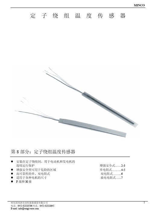
MINCO
F 级(155℃)RTDs 元件
铂(0.00392TCR),100Ω±0.5%,0℃ 铂(0.00385TCR),100Ω±0.12%,0℃ (符合 EN60751 B 级) 铂(0.00385TCR),100Ω±0.5%,0℃ 铜(0.00427TCR),10Ω±0.2%,25℃ 镍(0.00672TCR),120Ω±0.5%,0℃
E-mail: info@
双电阻式定子绕组温度传感器
MINCO
规格 温度限制:180℃(356℉),H 级。
概要 双电阻式定子绕组温度传感器为发电机和电动机提供 一个额外保护。第二个电阻测量元件可以在第一个元件 一旦被损坏时使用,或者其中一个用于机器的温度输入 显示,另一个用于控制室的监控。
规格 温度限值: F 级:155℃(311℉) H 级:180℃(356℉)。
主体材质: F 级:环氧玻璃 H 级:高温环氧玻璃。 标准型号(其他请指定):
哈尔滨同济自动化装备成套有限公司
4
电话:0451-82328506 传真:0451-82328645
E-mail: info@
导线:2,3,或者 4 线制,标准铜线带 PTFE 或者聚酰 亚胺绝缘,其它导线涂层请指定。
0.125”:AWG18; 0.078”:AWG22; 0.050”:AWG26; 0.030”:AWG30(无凸起);
AWG18(0.110” 凸起); 电缆(0.110” 凸起)。
电介质强度:3200VRMS 60Hz,1-5 秒在导线和外部平 滑主体的表面上测试。
铂 (0.00385 TCR) 100Ω±0.12,0℃
符合 IEC751 B 级 S100050PD S100051PD S100052PD S100053PD S100054PD S100055PD
ETS1701-100-Y00说明书
ETS1701-100-Y00说明书
贺德克ETS-1701-100-Y00温度传感器说明书:
ETS1700
可用版本:
标准
ETS1700电子温度开关主要与专门为储罐安装开发的TFP100温度传感器一起使用。
4个字符的显示屏可以显示当前温度,切换点之一或最大温度值。
最高温度值分别表示自设备开机或自上次复位以来发生的最高温度。
例如,可以使用4个开关量输出来控制液压设备的加热和冷却过程。
可以通过薄膜键盘非常容易地设置彼此独立的四个开关点和复位点。
模拟量输出(4…20mA或0…10V)可集成到监视系统中(例如使用SPS)。
4位数字显示
通过按键编程简单处理
4个极限值继电器,开关点和复位点可以相互独立调节
可以选择模拟输出信号(4…20mA或0…10V)
许多有用的附加功能
可以选择安装位置(上下左右的传感器连接,键盘和显示屏可以旋转180°)
贺德克EDS-3448-5-0600-000
贺德克ETS-386-2-150-Y00
贺德克EDS-345-1-250-000 贺德克EDS-3446-3-0100-000 贺德克EDS-3446-2-0100-000 贺德克EDS-3448-5-0100-000。
XH-W3001温度传感器说明书

XH-W3001温度传感器说明书
XH-W3001温度传感器是用铂金属丝制成的测温度电阻器,可用来测量各种液体、气体等流体的温度。
具有精度高、分辨率好,安全可靠、使用方便等优点,也可以直接测量各种生产过程中的液体、蒸气和气体介质的温度。
一、原理
本传感器是利用铂金属( PT100)在温度变化时自身电阻也随着
变化的特性来测量温度的。
它的受热元件是利用细铂丝均匀的双绕在绝缘材料制成的骨架上。
二、技术指标
1、0C对应电阻为100日, 100C对应电阻为138.5 Q
2、测量范围: -200~500"C
3、时间参数: <5 秒
4、外型尺寸:参照定货要求
三、安装使用方法及注意事项
1、本温度传感器通过螺纹固定。
在固定的时候切记不要用力过度,以免损坏传感器。
2、如传感器有杂质粘附于传感器上,要及时清洗,保证传感器可靠、准确运行。
3、线缆的铺设以不防碍现场工作人员的现场操作和不易被砸碰、损坏且架设安全可靠为原则下亚线制四线制。
4.传感器接触的介质应为经常流动的介质,这样才能保证所测值
的准确性。
四、故障现象及现场处理办法
1.如果温度传感器在使用过程中发生故障,如无信号输出或超过标准输出,首先应检查线缆的断线、短路及接线的脱落。
2、怀疑温度传感器有故障,可用万用表测量铂电阻的电阻值是否在正常范围之内。
如铂电阻的输入正常,则应检查上位仪表。
3、本传感器出厂时已作密封处理,如出现故障,请送厂里维修,用户不要自行拆卸。
4、本传感器故障,可免费维修或更换,终身维修。
本质安全型多通道光纤甲烷传感器说明书
ICS17.180.99CCS N10CSOE中国光学工程学会团体标准T/CSOE0001—2023本质安全型多通道光纤甲烷传感器Intrinsically Safe Multi-channel Optical Fiber Methane Sensors2023-07-17发布2023-07-31实施目次前言 (Ⅱ)1范围 (1)2规范性引用文件 (1)3术语和定义 (1)4系统结构 (2)5系统功能 (3)5.1基本功能 (3)5.2输出信号制式 (3)6技术要求 (3)6.1外观及结构 (3)6.2分辨力 (3)6.3测量值的重复性和测量误差 (3)6.4工作电压范围 (4)6.5光纤传输距离对测量误差的影响 (4)6.6工作稳定性 (4)6.7响应时间(T90) (4)6.8报警功能 (4)6.9绝缘电阻 (4)6.10工频耐压 (4)6.11环境适应性 (4)6.12防爆要求 (6)6.13电磁兼容性 (6)7试验方法 (6)7.1试验条件 (6)7.2测试方法 (7)8检验规则 (12)8.1概述 (12)8.2出厂检验 (13)8.3型式检验 (13)9标志、包装、使用说明书、运输和贮存 (14)9.1标志 (14)9.2包装 (14)9.3使用说明书 (14)9.4运输 (14)9.5贮存 (15)附录A(资料性)甲烷气体爆炸下限与体积浓度的换算关系 (16)前言本文件按照GB/T1.1—2020《标准化工作导则第1部分:标准化文件的结构和起草规则》的规定起草。
请注意本文件的某些内容可能涉及专利。
本文件的发布机构不承担识别专利的责任。
本文件由中国光学工程学会提出。
本文件由中国光学工程学会归口。
本文件起草单位:山东微感光电子有限公司、国家石油天然气管网集团有限公司科学技术研究总院分公司、山东省科学院激光研究所、天地(常州)自动化股份有限公司、中国科学院合肥物质科学研究院、南方科技大学、重庆大学、华中科技大学、厦门大学、山东星冉信息科技有限公司、光力科技股份有限公司。
KCT18B20产品规格书

KCT18B20 高精度单总线接口温度传感器
详细说明
图 1 展示的 KCT18B20 功能框图包括:64-BIT ROM 用于存放唯一的芯片编码序列号,暂存器中有两个字 节用来存放温度数据,两个字节是报警阀值寄存器 Th 和 Tl,一个字节用于可配置寄存器 Tc 放置用户设定 的温度转换分辨率值。报警阀值寄存器和可配置寄存器的值通过以下将要介绍的 copy scratchpad 挃令拷 贝到 MTP 中(数据在掉电后保持,上电后自动召回到寄存器中,也可以通过下面介绍的挃令召回)。 暂存器
图 6 温度寄存器数据分布图 BYTE 2~4: BYTE2 和 BYTE3 为配置温度报警上下阀值;BYTE 4 为配置温度转换分辨率的寄存器,图 7 为其格式图。
图 7 分辨率配置寄存器格式图 V0.5| 6/12
具体设置分辨率(配置 R1 和 R2)的值见表 1
KCT18B20 高精度单总线接口温度传感器
表 1 分辨率配置值以及对应分辨率 BYTE 5~7: 保留字节位,属性为只读,默认值如图 5 所示。
BYTE 8: CRC 校验位,存放校验数据,校验原理见下面 CRC 校验码生成器。
64 位可灵活设置的 ROM 编码
每颗芯片都有一个唯一的 64 位的 ROM 编码,幵且可根据需求为用户定制这个 ROM 编码。
非易失存储器
(测试条件:从-55℃ 到 +140℃; VDD 供电从 3.3V 到 5.5V)
参数
工作温度条件
最小值
典型值
写入周期时间
从-40℃到 +85℃
2
写入次数
从-40℃到 +85℃
数据保存时间
≤85℃
10
Omega TX801TC系列热感应传感器产品指南说明书

An OMEGA Technologies CompanyU s e r 's G u i d ee-mail:**************TX801TC SERIESTHERMOCOUPLE TRANSMITTERWhere Do I .ind Everything I Need for Process Measurement and Control?OMEGA...Of Course!TEMPERATUREThermocouple, RTD & Thermistor Probes, Connectors, Panels & Assemblies Wire: Thermocouple, RTD & Thermistor Calibrators & Ice Point ReferencesRecorders, Controllers & Process Monitors Infrared PyrometersPRESSURE, STRAIN AND .ORCE Transducers & Strain Gauges Load Cells & Pressure Gauges Displacement Transducers Instrumentation & Accessories.LOW/LEVELRotameters, Gas Mass Flowmeters & Flow Computers Air Velocity IndicatorsTurbine / Paddlesheel Systems Totalizers & Batch ControllerspH/CONDUCTIVITYpH Electrodes, Testers & Accessories Benchtop/Laboratory MetersControllers, Calibrators, Simulators & Pumps Industrial pH & Conductivity Equipment DATA ACQUISITIONData Acquisition & Engineering Software Communications-Based Acquisition Systems Plug-in Cards for Apple, IBM & Compatibles Datalogging SystemsRecorders, Printers & Plotters HEATERS Heating CableCartridge & Strip Heaters Immersion & Band Heaters Flexible Heaters Laboratory HeatersENVIRONMENTALMONITORING AND CONTROL Metering & Control Instrumentation Refractometers Pumps & TubingAir, Soil & Water MonitorsIndustrial Water & Wastewater TreatmentpH, Conductivity & Dissolved Oxygen InstrumentsM-3802/0302✔✔✔✔✔✔✔✔✔✔✔✔✔✔✔✔✔✔✔✔✔✔✔✔✔✔✔✔✔✔✔✔✔OMEGAOMEGAnet SM On-Line Service Internet e-mail **************Servicing North America:USA:One Omega Drive, Box 4047ISO 9001 Certified Stamford, CT 06907-0047Tel: (203) 359-1660FAX: (203) 359-7700e-mail:**************Canada:976 BergarLaval (Quebec) H7L 5A1Tel: (514) 856-6928FAX: (514) 856-6886e-mail:****************.or immediate technical or application assistance: USA and Canada:Sales Service: 1-800-826-6342 / 1-800-TC-OMEGA SMCustomer Service: 1-800-622-2378 / 1-800-622-BEST SMEngineering Service: 1-800-872-9436 / 1-800-USA-WHEN SMTELEX: 996404 EASYLINK: 62968934 CABLE: OMEGA Mexico andLatin America:Tel: (95) 800-TC-OMEGA SM FAX: (95) 203-359-7807En Espanol: (203) 359-7803e-mail:*****************Servicing Europe:Benelux:Postbus 8034, 1180 LA Amstelveen, The NetherlandsTel: (31) 20 6418405FAX: (31) 20 6434643Toll Free in Benelux: 06 0993344e-mail:************Czech Republic:ul. Rude armady 1868, 733 01 Karvina-Hranice, Czech RepublicTel: 420 (69) 6311627FAX: 420 (69) 6311114e-mail:***************France:9, rue Denis Papin, 78190 TrappesTel: (33) 130-621-400FAX: (33) 130-699-120Toll Free in France: 0800-4-06342e-mail:****************Germany/Austria:Daimlerstrasse 26, D-75392 Deckenpfronn, GermanyTel: 49 (07056) 3017FAX: 49 (07056) 8540Toll Free in Germany: 0130 11 21 66e-mail:*****************United Kingdom:25 Swannington Road,P.O. Box 7, Omega Drive,ISO 9001 Certified Broughton Astley, Leicestershire,Irlam, Manchester,LE9 6TU, England M44 5EX, EnglandTel: 44 (1455) 285520Tel: 44 (161) 777-6611FAX: 44 (1455) 283912FAX: 44 (161) 777-6622Toll Free in England: 0800-488-488e-mail:************It is the policy of OMEGA to comply with all worldwide safety and EMC/EMI regulations that apply. OMEGA is constantly pursuing certification of its products to the European New Approach Directives. OMEGA will add the CE mark to every appropriate device upon certification.The information contained in this document is believed to be correct but OMEGA Engineering, Inc. accepts no liability for any errors it contains, and reserves the right to alter specifications without notice.WARNING: These products are not designed for use in, and should not be used for, patient connected applications.OMEGA ENGINEERING, INC. warrants this unit to be free of defects in materials and workmanship for a period of 13 months from date of purchase. OMEGA Warranty adds an additional one (1) month grace period to the normal one (1) year product warranty to cover handling and shipping time. This ensures that OMEGA’s customers receive maximum coverage on each product.If the unit should malfunction, it must be returned to the factory for evaluation. OMEGA’s Customer Service Department will issue an Authorized Return (AR) number immediately upon phone or written request. Upon examination by OMEGA, if the unit is found to be defective it will be repaired or replaced at no charge. OMEGA’s WARRANTY does not apply to defects resulting from any action of the purchaser, including but not limited to mishandling, improper interfacing, operation outside of design limits, improper repair, or unau-thorized modification. This WARRANTY is VOID if the unit shows evidence of having been tampered with or shows evidence of being damaged as a result of excessive corrosion; or current, heat, moisture or vibra-tion; improper specification; misapplication; misuse or other operating conditions outside of OMEGA’s con-trol. Components which wear are not warranted, including but not limited to contact points, fuses, and triacs. OMEGA is pleased to offer suggestions on the use of its various products. However, OMEGA neither assumes responsibility for any omissions or errors nor assumes liability for any damages that result from the use of its products in accordance with information provided by OMEGA, either verbal or written. OMEGA warrants only that the parts manufactured by it will be as specified and free of defects. OMEGA MAKES NO OTHER WARRANTIES OR REPRESEN-TATIONS OF ANY KIND WHATSOEVER, EXPRESSED OR IMPLIED, EXCEPT THAT OF TITLE, AND ALL IMPLIED WARRANTIES INCLUDING ANY WARRANTY OF MERCHANTABILITY AND FITNESS FOR A PARTICULAR PURPOSE ARE HEREBY DIS-CLAIMED. LIMITATION OF LIABILITY: The remedies of purchaser set forth herein are exclusive and the total liability of OMEGA with respect to this order, whetherbased on contract, warranty, negliegence, indemnification, strict liability or otherwise, shall not exceed the purchase price of the component upon which liability is based. In no event shall OMEGA be liable for consequential, incidental or special damages.WARRANTY/DISCLAIMERCONDITIONS: Equipment sold by OMEGA is not intended to be used, nor shall it be used: (1) as a “Basic Component” under 10 CFR 21 (NRC), used in or with any nuclear installation or activity; or (2) in medical applications or used on humans, or misused in any way, OMEGA assumes no responsibility as set forth in our basic WARRANTY/DISCLAIMER language, and additionally, purchaser will indemnify OMEGA and hold OMEGA harmless from any liability or damage whatsoever arising out of the use of the Product(s) in such a manner.RETURN REQUESTS/INQUIRIESDirect all warranty and repair requests/inquiries to the OMEGA Customer Service Department. BEFORE RETURNING ANY PRODUCT(S) TO OMEGA, PURCHASER MUST OBTAIN AN AUTHORIZED RETURN (AR) NUMBER FROM OMEGA’S CUSTOMER SERVICE DEPARTMENT (IN ORDER TO A VOID PROCESSING DELAYS). The assigned AR number should then be marked on the outside of the return package and on any correspondence.The purchaser is responsible for shipping charges, freight, insurance and proper packaging to prevent break-age in transit.FOR WARRANTY RETURNS, please have thefollowing information available BEFORE contact-ing OMEGA:1. P.O. number under which the product was PURCHASED,2. Model and serial number of the product underwarranty, and3. Repair instructions and/or specific problemsrelative to the product.FOR NON-WARRANTY REPAIRS, consultOMEGA for current repair charges. Have thefollowing information available BEFORE contacting OMEGA:1. P.O. number to cover the COST of the repair,2. Model and serial number of product, and3. Repair instructions and/or specific problemsrelative to the product.OMEGA’s policy is to make running changes, not model changes, whenever an improvement is possible. This affords our customers the latest in technology and engineering.OMEGA is a registered trademark of OMEGA ENGINEERING, INC.Copyright 1996 OMEGA ENGINEERING, INC. All rights reserved. This document may not be copied, photocopied, reproduced, translated, or reduced to any electronic medium or machine-readable form, in whole or in part, without prior written consent of OMEGA ENGINEERING, INC.FeatureslAvailable for J, K, N, R, S, & T Thermocouples.l Field Programmable Input and Output Ranges.l Bi-Polar Input and Output Ranges.l Isolated Input to Output 1.6kV.l High Accuracy.l Linear With Temperature.l Internal Cold Junction Compensation.l Universal AC/DC Power Supply.l Compact DIN Rail Mount Enclosure.lAvailable Standard or Special Calibration.TX801TC Programmable Isolating Thermocouple TransmitterQuality Assurance Programme.The modern technology and strict procedures of the ISO9001 Quality Assurance Programme applied during design,development, production and final inspection grant long term reliability of the instrument.Programmable Isolating Thermocouple Input to DC Currentor DC Voltage Output Transmitter.Input Note 1: The input range mustmin / max range of Note 2: Each TX801TC is only rangeable within thespecified 'Thermo-couple Type'.- Impedances1M Ω Min. Input Impedance.100Ω Max. Thermocouple Lead Resistance.Output- Voltage Field Programmable From ±500mVdc to ±12Vdc.Maximum Output Drive = 10mA.- CurrentField Programmable From ±1mAdc to ±20mAdc.Maximum Output Drive = 10Vdc. (500Ω @ 20mA.)Universal P/S-Standard High (H)70~270Vac and 80~380Vdc; 50/60Hz; 4VA.-Standard Mid (M)24~80Vac and 20~90Vdc; 50/60Hz; 4VA.-Low Voltage (L)8~30Vac and 8~30Vdc; 50/60Hz; 4VA.-Circuit Sensitivity<±0.001%/V FSO Typical.Cold Junction Compensation Accuracy.<0.03C/C (0.06F/F) Typical.Repeatability <±0.1% FSO Typical.Ambient Drift <±0.01%/C FSO Typical.Noise Immunity 125dB CMRR Average. (1.6kV Peak Limit.)R.F. Immunity <1% Effect FSO Typical.Isolation Voltage 1.6kVac/dc Input to Output for 60sec.Response Time200msec Typical. (From 10 to 90% 50msec Typical.)Operating Temperature 0~70C.Storage Temperature -20~80C.Operating Humidity 90% Max. RH Non-Condensing.ConstructionSocket Plug-In Type With Barrier Terminals.Note 1.Specifications based on Standard Calibration Unit, unless otherwise specified.Note 2.Due to ongoing research and development, designs, specifications, and documentation are subject to change without notification.No liability will be accepted for errors, omissions or amendments to this specification.The Proper Installation & Maintenance of TX801TC.MOUNTING.(1)Mount in a clean environment in an electrical cabinet on 35mm, symetrical, mounting rail.(2)Do not subject to vibration or excess temperature or humidity variations, and avoid mounting in cabinets with power control equipment.(3)To maintain compliance with the EMC Directives the TX801TC must be mounted in a fully enclosed steel cabinet. The cabinet must be properly earthed, with appropriate input / output entry points and cabling.WIRING.(1) A readily accessible disconnect device and overcurrent device must be incorporated in the the power supply wiring.(2)All o utput c ables s hould b e g ood q uality o verall s creened I NSTRUMENTATION C ABLE w ith t he s creen e arthed at one end only.(eg. Austral Standard Cables B5102ES.)(3)It is recommended that you do not ground current loops and use power supplies with ungrounded outputs.(4)Lightning arrestors should be used on inputs and outputs when there is a danger from this source.THERMOCOUPLES.(1)Avoid locating the thermocouple where it will be in a direct flame.(2)Never insert a porcelain or refactory tube suddenly in a hot area. Pre-heat gradually while installing.(3)Locate it where the average temperature will be measured. It should be representative of the mass.(4)Immerse the thermocouple enough so that the measuring junction is entirely in the temperature to be measured:nine to ten times the diameter of the protection tube is recommended. Heat that is conducted away from the junction causes an error in reading.(5)If t he t hermocouple i s m ounted h orizontally a nd t he t emperature i s a bove t he s oftening p oint o f t he t ube, a s upport should be provided to prevent the tube sagging. Otherwise install the tube vertically.(6)Keep t he j unction h ead a nd c old j unction i n t he a pproximation o f t he a mbient t emperature. E specially i n t he N oble Metal Class.EXTENSION WIRE.(1)Use the correct thermocouple extension or compensation cable. i.e. Thermocouple type, insulation type,correct colour coding.(2)If possible install extension or compensation cable in a grounded conduit. Never run electrical wires in the same conduit.(3)All wires that must be spliced should be soldered, or the correct termination block used.COMMISSIONING.(1)Once all the above conditions have been met and the wiring checked apply power to the TX801TC and allow five minutes to stabilize.(2)If the input range has been altered from factory setting, the TX801TC should be re-calibrated.(3)Due to the limits of error in a standard thermocouple probe and extension wire, an error can occur. (eg. For Type K an error of 2.2C or 0.75% of Span can occur. {which ever is greater}) To remove this error use a calibration standard thermocouple at the same immersion depth and adjust the Zero trimpot on the top of the TX801TC enclosure with a small screwdriver until the two levels agree. (Clockwise to increase the output reading and anti-clockwise to decrease the output reading.)MAINTENANCE.(1)Replace defective protection tubes.(2)Check out extension and compensating cable circuits.(3)Repeat (3) of Commissioning.(4)Do it regularly - at least once every 6 months.8PFA Octal Termination Base11.02-3m m80m m Side View 120m m Top View51m m84m m80m m100m mTop View58m mM i n i m u m d i s t a n c e b e t w e e n u n i t s .Output Range Programming Table.Notes:1/Switch status 1 = ON 0 = OFF.TX801TC Input Range Programming Table.Note: Switch status: 1 = ON, 0 = OFF, X = DON'T CARE.TX801TC Input Programming.Always set OUTPUT range first , then INPUT range.SPAN = Maximum Input - Zero Offset deg C SPAN GAIN =Y .deg F SPAN GAIN =2 x Y .SPAN SPAN deg C ZERO GAIN =Zero Offset deg F ZERO GAIN =Zero Offset Z2 x ZIf Zero is:1/ Positive, put S5-1 OFF.2/ Negative, put S5-1 ON.Sensor Fail:1/ For downscale sensor fail drive put S1-8 OFF. 2/ For upscale sensor fail drive put S1-8 ON.Note:(a)Enter the Zero or Span gain value into the appropriate Zero or Span DIP switch.(b)If the ZERO GAIN exceeds 63, then the input range must be factory calibrated.So if a gain value of 28 is required, put DIP switch No's 3, 4, 5 OFF (ie, gains of 4 + 8 + 16 = 28) and all the other DIP switches ON.DIP switches and trimpots are accessed by removing the small rectangular lid on the top of the TX801TC enclosure.Examples of Input Connections.Terminations.Output 1+Ve2-Ve Input3+T/C 4-T/C P/S7~AC / +DC 8~AC / -DCNotes:1/ H1 is approx 4cm (1½") behind the 'S' trimpot.2/ Exceeding voltage ranges may damage the unit.3/ Ensure the enclosure label is correctly labelled for the link position.4/ Adjust H1 jumper with a pair of needle nose pliers.5/ Low Voltage Power Supply version is fixed, and has no link. This must be ordered separately.。
E2B-M18KN16-WZ-B1接近开关
E2B 接近传感器世界新标准经济型接近传感器,完美使用各种场合,全机种·高品质·低价格 E2B 种类:信息更新: 2017年11月18日尺寸 检测 距离 连接方式 (见“注1”) 螺纹 长度 输出类型动作模式NO动作模式NCM8(不锈钢)(见 “注2”) 单倍距离型屏蔽型 1.5mm 导线引出型标准 型 PNP E2B-S08KS01-WP-B1 2M E2B-S08KS01-WP-B2 2M NPN E2B-S08KS01-WP-C1 2M E2B-S08KS01-WP-C2 2M 长螺 纹型 PNP E2B-S08LS01-WP-B1 2M E2B-S08LS01-WP-B2 2M NPN E2B-S08LS01-WP-C1 2M E2B-S08LS01-WP-C2 2MM8接插件型(3针) 标准 型 PNP E2B-S08KS01-MC-B1E2B-S08KS01-MC-B2 NPN E2B-S08KS01-MC-C1E2B-S08KS01-MC-C2 长螺 纹型 PNP E2B-S08LS01-MC-B1E2B-S08LS01-MC-B2 NPN E2B-S08LS01-MC-C1E2B-S08LS01-MC-C2 非屏蔽型 2mm 导线引出型标准 型 PNP E2B-S08KN02-WP-B1 2ME2B-S08KN02-WP-B2 2M NPN E2B-S08KN02-WP-C1 2ME2B-S08KN02-WP-C2 2M 长螺 纹型 PNP E2B-S08LN02-WP-B1 2M E2B-S08LN02-WP-B2 2M NPN E2B-S08LN02-WP-C1 2M E2B-S08LN02-WP-C2 2M M8接插件型(3针)标准 型 PNP E2B-S08KN02-MC-B1E2B-S08KN02-MC-B2 NPN E2B-S08KN02-MC-C1E2B-S08KN02-MC-C2 长螺 纹型 PNP E2B-S08LN02-MC-B1 E2B-S08LN02-MC-B2 NPN E2B-S08LN02-MC-C1 E2B-S08LN02-MC-C2 两倍距离型屏蔽型 2mm 导线引出型标准 型 PNP E2B-S08KS02-WP-B1 2M E2B-S08KS02-WP-B2 2M NPN E2B-S08KS02-WP-C1 2ME2B-S08KS02-WP-C2 2M 长螺 纹型 PNP E2B-S08LS02-WP-B1 2M E2B-S08LS02-WP-B2 2M NPN E2B-S08LS02-WP-C1 2M E2B-S08LS02-WP-C2 2M M8接插件型(3针) 标准 型 PNP E2B-S08KS02-MC-B1E2B-S08KS02-MC-B2 NPN E2B-S08KS02-MC-C1E2B-S08KS02-MC-C2 长螺 纹型 PNP E2B-S08LS02-MC-B1E2B-S08LS02-MC-B2 NPN E2B-S08LS02-MC-C1E2B-S08LS02-MC-C2 非屏蔽型 4mm 导线引出型标准 型 PNP E2B-S08KN04-WP-B1 2ME2B-S08KN04-WP-B2 2M NPN E2B-S08KN04-WP-C1 2ME2B-S08KN04-WP-C2 2M 长螺 纹型 PNP E2B-S08LN04-WP-B1 2M E2B-S08LN04-WP-B2 2M NPN E2B-S08LN04-WP-C1 2M E2B-S08LN04-WP-C2 2M M8接插件型(3针)标准 型 PNP E2B-S08KN04-MC-B1E2B-S08KN04-MC-B2 NPN E2B-S08KN04-MC-C1E2B-S08KN04-MC-C2 长螺 纹型 PNP E2B-S08LN04-MC-B1E2B-S08LN04-MC-B2 NPN E2B-S08LN04-MC-C1E2B-S08LN04-MC-C2注:1. 导线引出型的电缆长度有2m和5m两种。
温度传感器(Pt1000)

见“特定参数”
25
ESMT
ESM - 10
ESM - 11
ESMB - 12 材质
ESMC
ESMU - 100 / - 250
ESMU - 100 / - 250 (Cu)
外套
ESMT
ESM - 10
电气连接
ESM-11 ESMB - 12
ESMC
ESMU - 100 / - 250
ESMT / ESM - 10
154
ESMU
VD.74.I6.41 C Danfoss 11/2003
(A) (B) (C)
087B1182 和-1183
不锈钢(AIS1316) 不锈钢(AIS1316)
087B1180 和-1181 铜 (Cu)
黄铜
BC-HM
装在套管中的ESMB
最大偏差 2K 32s (在水中) 160s (空气中) 20s (在水中) 140s (空气中)
BC-HM
VD.74.I6.41 C Danfoss 11/2003
153
参数表
尺寸
温度传感器 ESM-10,ESM-11,ESMB-12,ESMC,ESMU
Danfoss A87B584.10
产品编号 084N1012 087B1164 087B1165 087B1184 087N0011 087B1180 087B1181 087B1182 087B1183
产品编号 087B1190 087B1191 087B1192 087B1193 041E0110
Danfoss A84N306.10
ESM - 11 / ESMC
安装
ESMB - 12
ESMU- 100 / - 250
- 1、下载文档前请自行甄别文档内容的完整性,平台不提供额外的编辑、内容补充、找答案等附加服务。
- 2、"仅部分预览"的文档,不可在线预览部分如存在完整性等问题,可反馈申请退款(可完整预览的文档不适用该条件!)。
- 3、如文档侵犯您的权益,请联系客服反馈,我们会尽快为您处理(人工客服工作时间:9:00-18:30)。
热电堆传感器规格书WXZ18-TS001
客户名称:
产品名称:热电堆传感器
产品规格:WXZ18-TS001
日期:2020-3-28
1.产品特征:
●MEMS热电堆芯片;
●TO-46封装;
●高灵敏度;
●5.5μm长波通滤光片;
●高精度NTC.
2.产品应用
●非接触温度测量;
●耳温计额温计;
●生产制造温度连续测量;
●消费类电子产品;
●家用电器温度测量。
3.最大额定温度
参数数值单位工作温度-30----100℃
存储温度-40---125℃
4.性能
参数数值单位条件
芯片面积 1.5×1.5mm2
薄膜面积0.75×0.75mm2
视场83º50%最大信号热电堆电阻50±10%KΩTa=25℃
噪声电压30±2nV/Hz1/2Ta=25℃
噪声等级功率0.37nW/Hz1/2500K,1HZ
500K,5.5μm 响应率81V/W
(长波通)
电阻温度系数0.1%/℃Ta=25--75℃时间常数20mS
滤光片探测率 5.9e7cm HZ1/2W
F5.5,500K,1HZ NTC阻值100±2%KΩTa=25℃NTC B值3950±0.5%K B25/50
5.典型性能曲线
6.光学特点
7.滤光片规格
参数数值单位条件
透过率
5.5μm长波通
波长范围
平均透过率≥75% 5.5--14μm 平均截止率1%<5μm
8.电气连接
引脚1234
定义热电堆+NTC热电堆-GND
9.NTC R-T表:
温度(℃)电阻(KΩ)温度(℃)电阻(KΩ)温度(℃)电阻(KΩ)
-20898.1742984.1147813.009 -19849.3463080.5977912.573 -18803.6043177.2438012.154 -17760.7183274.0458111.749 -16720.4773370.9948211.36 -15682.6893468.0838310.985 -14647.1753565.3068410.624 -13613.7723662.6558510.035 -12582.3313760.125869.94 -11552.7163857.708879.616 -10524.83955.401889.304 -9498.4684053.196899.003 -8473.6154151.09908.713 -7450.1434249.078918.434 -6427.9644347.154928.164 -5406.9944445.315937.904 -4387.1584543.556947.653 -3368.3854641.874957.41 -2350.6124740.264967.176 -1333.7774838.72497 6.951 0315.684937.25198 6.733 1302.7065035.8499 6.523 2288.375134.488100 6.173 3274.7735233.194101 6.124 4261.8725331.955102 5.935 5249.635430.767103 5.752 6238.0095529.629104 5.576 7226.9765628.537105 5.405 8216.4985727.491106 5.241 9206.5455826.488107 5.082 10195.295925.525108 4.928 11188.1056024.602109 4.779 12179.5666123.716110 4.636
13171.4496222.866111 4.497 14163.7326322.049112 4.363 15156.3946421.265113 4.234 16149.4156520.513114 4.109 17142.7766619.789115 3.987 18136.4616719.095116 3.87 19130.4516818.427117 3.757 20124.7336917.785118 3.648 21119.2897017.168119 3.542 22114.1077116.575120 3.439 23109.1737216.005121 3.34 24104.4757315.456122 3.245 251007414.929123 3.152 2695.7367514.421124 3.062 2791.6747613.932125 2.976
2887.8037713.462
10.尺寸示意图:。