CWYK 人防警报控制设备说明书-终端控制器
音频代码一声音操作中心管理设备和终端警报指南说明书

Alarms Guide ContentsContents1Introduction (13)2Standard Events (15)2.1Cold Start (15)2.2Link Down (15)2.3Link Up (16)2.4Entity Configuration Change (16)2.5Authentication Failure (17)3Management Alarms (19)3.1EMS Trap Receiver Binding Error (19)3.2GW Connection Alarm (20)3.3GW Mismatch Alarm (21)3.4EMS Server Started (22)3.5Software Replaced (23)3.6Hardware Replaced (23)3.7HTTP/HTTPS Access Disabled (24)3.8PM File Generated (24)3.9PM Polling Error (25)3.10Cold Start Missed (25)3.11Security Alarm (26)3.12Security Event (27)3.13Topology Update Event (27)3.14Topology File Event (29)3.15Synchronizing Alarms Event (29)3.16Synchronizing Active Alarms Event (30)3.17Alarm Supression Alarm (30)3.18EMS Keep Alive Alarm (31)3.19Pre-provisioning Alarm (31)3.20Disk Space Alarm (32)3.21Oracle Disk Space Alarm (33)3.22License Alarm (34)3.23Synchronizing Alarms (35)3.24Floating License Extended (35)3.25CLM Device Report Alarm (36)3.26CLM Register Successful Event (36)3.27CLM Register Failure Alarm (37)3.28CLM Failure to Send Usage Report Alarm (37)3.29CLM Failure to Send Extended Usage Report Alarm (38)3.30CLM Service Shutdown Alarm (38)4Voice Quality Package Alarms (39)Version 7.4 3 Managed Devices and EndpointsAlarms4.1OVOC QoE - Failed Calls Alarm (39)4.2OVOC QoE – Poor Voice Quality Alarm (39)4.3OVOC QoE - Average Call Duration Alarm (40)4.4OVOC QoE - License Key Alarm (41)4.5OVOC QoE - System Load Alarm (42)4.6Call Details Storage Level Change (42)4.7Call Quality Monitoring Connection Status Alarm (43)4.8OVOC QoE - Skype for Business SQL Server Connection Lost Alarm (44)4.9OVOC QoE - Active Directory Server Connection Lost Alarm (44)4.10OVOC QoE - Media Bandwidth Alarm (45)4.11OVOC QoE - Rule Max Concurrent Calls Alarm (46)5Endpoint Alarms (47)5.1Registration Failure Alarm (47)5.2Lync Survivable Mode Start Alarm (47)5.3Lync Login Failure Alarm (48)5.4Endpoint License Alarm (48)5.5Endpoint Server Overloaded Alarm (49)5.6IP Phone Speaker Firmware Download Failure (50)5.7IP Phone Speaker Firmware Upgrade Failure (51)5.8IP Phone Conference Speaker Connection Failure (51)5.9IP Phone General Local Event (52)5.10IP Phone Web Successive Login Failure (53)5.11IP Phone Requires Reset (54)6Device Alarms (55)6.1Support Matrix (55)6.2Common Device Alarms (63)6.2.1Board Fatal Error (63)6.2.2Configuration Error (64)6.2.3Initialization Ended (64)6.2.4Board Resetting Following Software Reset (65)6.2.5Feature Key Related Error (66)6.2.6Gateway Administrative State Changed (66)6.2.7No Free Channels Available (68)6.2.8Gatekeeper/Proxy not Found or Registration Failed (69)6.2.9Ethernet Link Down Alarm (71)6.2.10System Component Overloaded (72)6.2.11Active Alarms Table Overflow (73)6.2.12Operational State Change (74)6.2.13Keep Alive Trap (75)6.2.14NAT Traversal Alarm (76)6.2.15Enhanced BIT Status Trap (77)6.2.16Threshold of Performance Monitored Object Exceeded (78)6.2.17HTTP Download Result (78)6.2.18IPv6 (79)Alarms Guide 4 Document #: LTRT-41608Alarms Guide Contents6.2.19SAS Emergency Mode Alarm (79)6.2.20Software Upgrade Alarm (80)6.2.21NTP server Status Alarm (80)6.2.22LDAP Lost Connection (81)6.2.23SSH Connection Status [Event] (81)6.2.24OCSP Server Status Alarm (82)6.2.25Media Process Overload Alarm (83)6.2.26Ethernet Group Alarm (83)6.2.27Media Realm BW Threshold Alarm (84)6.2.28Certificate Expiry Notification (85)6.2.29Web User Access Disabled (86)6.2.30Proxy Connection Lost (87)6.2.31IDS Policy Alarm (89)6.2.32IDS Threshold Cross Notification (90)6.2.33IDS Blacklist Notification (91)6.2.34Proxy Connectivity (92)6.2.35Web User Activity Log Trap (93)6.2.36License Pool Infra Alarm (94)6.2.37License Pool Application Alarm (96)6.2.38Answer-Seizure Ratio Threshold Alarm (96)6.2.39Average Call Duration Threshold Alarm (97)6.2.40Network Effectiveness Ratio Threshold Alarm (98)6.2.41IP Group No Route Alarm (99)6.2.42License Pool Over Allocation Alarm (100)6.2.43NGINX Configuration is not Valid (102)6.2.44NGINX Process is not Running (102)6.2.45Cloud License Manager Alarm (103)6.2.46Floating License Alarm - Not Enough Memory to Allocate 'Custom' Profile (105)6.3Specific Hardware Alarms (105)6.3.1Temperature Alarm (105)6.3.2Fan Tray Alarm (107)6.3.3Power Supply Alarm (108)6.4HA System Alarms (109)6.4.1HA System Fault Alarm (109)6.4.2HA System Configuration Mismatch Alarm (113)6.4.3HA System Switch Over Alarm (114)6.4.4Hitless Software Upgrade Alarm (115)6.4.5Redundant Board Alarm (116)6.4.6HA Network Watchdog Status Alarm (117)6.4.7Cluster HA Alarm (118)6.4.8License Key Hitless Upgrade Alarm (119)6.4.9HA Network Mismatch Alarm (119)6.4.10HA Network Monitor Alarm (120)6.4.11HA Ethernet Group Alarm (121)6.5Media Transcoder Alarms (122)6.5.1Media Transcoder Network Failure (122)6.5.2Media Transcoder Software Upgrade Failure (123)6.5.3Media Transcoder High Temperature Failure (124)6.5.4Media Transcoder Fan Tray Module Failure (125)6.5.5Media Transcoder Power Supply Module Failure (126)6.5.6Media Cluster Alarm (126)Version 7.4 5 Managed Devices and EndpointsAlarms6.5.7Remote Interface Alarm (128)6.6MP-1288 Alarms (129)6.6.1Module Service Alarm (129)6.6.2Module Operation Alarm (130)6.6.1Port Service Alarm (132)6.7MSBR Alarms (133)6.7.1WAN Link Alarm (133)6.7.2Power Over Ethernet Status [Event] (134)6.7.3Wireless Cellular Modem Alarm (135)6.7.4Data Interface Status (135)6.7.5NQM Connectivity Alarm (136)6.7.6NQM RTT Alarm (136)6.7.7NQM Jitter Alarm (137)6.7.8NQM Packet Loss Alarm (138)6.7.9NQM MOS CQ Alarm (139)6.7.10NQM MOS LQ Alarm (140)6.8Mediant 3000 Hardware Alarms (141)6.8.1PEM Module Alarm (141)6.8.2SA Module Missing Alarm (142)6.8.3User Input Alarm (142)6.8.4TM Inconsistency (143)6.8.5TM Reference Status (143)6.8.6TM Reference Change (144)6.9PSTN Trunk Alarms (145)6.9.1D-Channel Status (145)6.9.2SONET Section LOF Alarm (146)6.9.3SONET Section LOS Alarm (147)6.9.4SONET Line AIS Alarm (148)6.9.5SONET Line RDI Alarm (149)6.9.6SONET/SDN IF Failure Alarm (150)6.9.7Trunk LOS Alarm (151)6.9.8Trunk LOF Alarm (152)6.9.9Trunk AIS Alarm (153)6.9.10Trunk RAI Alarm (154)6.9.11V5.2 Interface Alarm (155)6.9.12SONET Path STS LOP Alarm (156)6.9.13SONET Path STS AIS Alarm (157)6.9.14SONET Path STS RDI Alarm (158)6.9.15SONET Path Unequipped Alarm (159)6.9.16SONET Path Signal Label Alarm (159)6.9.17DS3 RAI Alarm (160)6.9.18DS3 AIS Alarm (161)6.9.19DS3 LOF Alarm (161)6.9.20DS3 LOS Alarm (162)6.9.21NFAS Group Alarm (163)6.9.22 B Channel Alarm (164)6.10Analog Port Alarms (165)6.10.1Analog Port SPI Out of Service (165)6.10.2Analog Port High Temperature (165)6.10.3Analog Port Ground Fault Out-of-Service Alarm (166)Alarms Guide 6 Document #: LTRT-41608Alarms Guide Contents6.11CloudBond 365 Alarms (166)6.11.1Commit License Failed (166)6.11.2Component Unreachable (167)6.11.3Component Restart (167)6.11.4Component Performance Counter General (168)6.11.5Component Performance Counter Service (169)6.11.6Component Service Status (170)6.11.7Component Event Viewer (170)6.11.8Component Event Viewer Past Hours (171)6.11.9Component Event Viewer Dropped (171)6.11.10Admin License Expired (172)6.11.11Alarm – Certificate Expired (172)6.11.12Alarm –Disk Space (173)6.12CCE Appliance Alarms (174)6.12.1Component Unreachable (174)6.12.2Event – Component Restart (175)6.12.3Component Performance Counter General (175)6.12.4Component Performance Counter Service (176)6.12.5Component Service Status (177)6.12.6Alarm – Admin System Cloud Status (178)6.12.7Alarm – Certificate Expired (178)6.12.8Alarm – CCE Wrong Operating (179)6.12.9Alarm – CCE Wrong Settings (180)6.12.10Alarm – CCE Disk Space (181)6.12.11Alarm – CCE Windows License (183)6.13SBA Alarms (184)6.13.1SBA Services Status Alarm (184)6.13.2Alarm – CPU Status (185)6.13.3Alarm – Memory Status (186)6.13.4Alarm – Disk Space (187)6.13.5Alarm – Certificate Expired (188)6.13.6Alarm – Performance Counter (189)Version 7.4 7 Managed Devices and EndpointsAlarmsThis page is intentionally left blank.Alarms Guide 8 Document #: LTRT-41608Alarms Guide 1.IntroductionNoticeInformation contained in this document is believed to be accurate and reliable at the time of printing. However, due to ongoing product improvements and revisions, AudioCodes cannot guarantee accuracy of printed material after the Date Published nor can it accept responsibilityfor errors or omissions. Updates to this document can be downloaded from https:///library/technical-documents.This document is subject to change without notice.Date Published: June-3-2018WEEE EU DirectivePursuant to the WEEE EU Directive, electronic and electrical waste must not bedisposed of with unsorted waste. Please contact your local recycling authority fordisposal of this product.Customer SupportCustomer technical support and services are provided by AudioCodes or by anauthorized AudioCodes Service Partner. For more information on how to buy technicalsupport for AudioCodes products and for contact information, please visit our Web siteat https:///services-support/maintenance-and-support.Version 7.4 9 Managed Devices and EndpointsAlarms Related DocumentationAlarms Guide 10 Document #: LTRT-41608Alarms Guide 1. Introduction Document Revision RecordDocumentation FeedbackAudioCodes continually strives to produce high quality documentation. If you have anycomments (suggestions or errors) regarding this document, please fill out theDocumentation Feedback form on our Web sitehttps:///documentation-feedback.Alarms This page is intentionally left blank.Alarms Guide 1. Introduction1 IntroductionThis document describes alarms that are raised by OVOC and by AudioCodes devicesand endpoints. These alarms are displayed in the One Voice Operations Center Webinterface.Supported alarms / events can fall into one of these three categories:⏹Standard traps: traps originated by the media gateway / server - all the standardtraps are treated are events.⏹Proprietary alarms / events: traps originated by the media gateway / server anddefined in the gateway proprietary MIB.⏹EMS alarms / events: traps originated by the EMS application and defined in theEMS proprietary MIB.To find out which traps are defined as Events refer to 'Alarm Name' or 'Alarm Title' fieldsin the table. All the events are marked with [Event] prefix. This is how events are markedin the EMS Alarms Browser and Alarms History windows.Each alarm / event described in this section includes the following information:Information Included in Each AlarmAlarms This page is intentionally left blank.Alarms Guide 2. Standard Events 2 Standard Events2.1 Cold StartCold Start2.2 Link DownLink DownAlarms 2.3 Link UpLink Up2.4 Entity Configuration ChangeEntity Configuration ChangeAlarms Guide 2. Standard Events 2.5 Authentication FailureAuthentication FailureAlarms This page is intentionally left blank.Alarms Guide 3. Management Alarms 3 Management Alarms3.1 EMS Trap Receiver Binding ErrorEMS Trap Receiver Binding ErrorAlarms 3.2 GW Connection AlarmGW Connection Alarm3.3 GW Mismatch AlarmGW Mismatch Alarm3.4 EMS Server StartedEMS Server Started3.5 Software ReplacedSoftware Replaced3.6 Hardware ReplacedHardware Replaced3.7 HTTP/HTTPS Access DisabledHTTP/HTTPS Access Disabled3.8 PM File GeneratedPM File Generated3.9 PM Polling ErrorPM Polling Error3.10 Cold Start MissedCold Start Missed3.11 Security AlarmSecurity Alarm3.12 Security EventSecurity Event3.13 Topology Update EventTopology Update Event3.14 Topology File EventTopology File Event3.15 Synchronizing Alarms EventSynchronizing Alarms Event3.16 Synchronizing Active Alarms EventSynchronizing Active Alarms Event3.17 Alarm Supression AlarmAlarm Supression AlarmAlarms Guide 3. Management Alarms 3.18 EMS Keep Alive AlarmEMS Keep Alive Alarm3.19 Pre-provisioning AlarmPre-provisioning AlarmAlarms3.20 Disk Space AlarmDisk Space AlarmAlarms Guide 3. Management Alarms 3.21 Oracle Disk Space AlarmOracle Disk Space AlarmAlarms 3.22 License AlarmLicense AlarmAlarms Guide 3. Management Alarms 3.23 Synchronizing AlarmsSynchronizing Alarms3.24 Floating License ExtendedFloating License ExtendedAlarms3.25 CLM Device Report AlarmCLM Device Report Alarm3.26 CLM Register Successful EventCLM Registration Successful EventAlarms Guide 3. Management Alarms 3.27 CLM Register Failure AlarmCLM Register Failure Alarm3.28 CLM Failure to Send Usage Report AlarmCLM Failure to Send Usage Report AlarmAlarms 3.29 CLM Failure to Send Extended Usage ReportAlarmCLM Failure to Send Extended Usage Report Alarm3.30 CLM Service Shutdown AlarmCLM Service Shutdown AlarmAlarms Guide 4. Voice Quality Package Alarms 4 Voice Quality Package Alarms4.1 OVOC QoE - Failed Calls AlarmOVOC QoE - Failed Calls Alarm4.2 OVOC QoE – Poor Voice Quality AlarmOVOC QoE - Poor Voice Quality AlarmAlarms4.3 OVOC QoE - Average Call Duration AlarmOVOC QoE - Average Call Duration AlarmAlarms Guide 4. Voice Quality Package Alarms 4.4 OVOC QoE - License Key AlarmOVOC QoE - License Key AlarmAlarms 4.5 OVOC QoE - System Load AlarmOVOC QoE - System Load Alarm4.6 Call Details Storage Level ChangeOVOC QoE Call Details Storage Level ChangeAlarms Guide 4. Voice Quality Package Alarms 4.7 Call Quality Monitoring Connection Status AlarmOVOC QoE - Call Quality Monitoring Connection Status AlarmAlarms4.8OVOC QoE - Skype for Business SQL Server Connection Lost AlarmOVOC QoE - Skype for Business SQL Server Connection Lost Alarm4.9OVOC QoE - Active Directory Server Connection Lost AlarmOVOC QoE - Active Directory Server Connection Lost AlarmAlarms Guide 4. Voice Quality Package Alarms4.10 OVOC QoE - Media Bandwidth AlarmOVOC QoE - Media Bandwidth AlarmAlarms 4.11 OVOC QoE - Rule Max Concurrent Calls AlarmOVOC QoE - Rule Max Concurrent Calls AlarmAlarms Guide 5. Endpoint Alarms 5 Endpoint Alarms5.1 Registration Failure AlarmIP Phone Registration Failure Alarm5.2 Lync Survivable Mode Start AlarmIP Phone Survivable Mode Start AlarmAlarms5.3Lync Login Failure AlarmIP Phone Lync Login Failure Alarm5.4 Endpoint License AlarmEndpoint License AlarmAlarms Guide 5. Endpoint Alarms5.5 Endpoint Server Overloaded AlarmEndpoint Server Overloaded AlarmAlarms5.6 IP Phone Speaker Firmware Download FailureIP Phone Speaker Firmware Download Failure。
《报警器说明书》word版
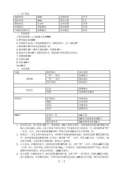
一.出厂默认主机控制面板:1.电源输入孔POWER2.警号输出端SIREN3.有线防区L1-L4(有线探测器信号一端接此端口,另一端接SP-4.喊话喇叭SP-同时也是接地线(G)5.喊话喇叭SP+(喇叭正极接SP+,负极接SP-)6.备电开关ON/OFF(内置电池开关,拨到ON开的位置可以充电)7.设置按键SET8.天线座ANT9.布防ARM灯10.GSM灯插入主机电源孔。
此时,主机上的6个防区灯和2个功能指示灯全部闪亮一下,同时蜂鸣器“哔”一长声;之后,主机开始检测GSM网络,网络正常的GSM指示灯3秒闪烁一次。
2.恢复出厂:首先关闭后备电池开关,同时断开电源适配器的电源,再按住[设置SET]按键不松开,此时接通电源适配器电源;3秒后,蜂鸣器“哔”一长声,所有LED灯亮一下后熄灭,最后松开按键。
主机设置全部被清除,恢复出厂值成功。
3.人工录音:在撤防状态下,连续轻按[设置SET]键三次,主机“哔”一长声,[布防ARM]灯闪烁(1秒一次),录音开始:距离主机正面30cm ,中等语音,标准普通话录制用户信息;防区灯根据时间依次熄灭,录音自动结束,,[ARM]灯熄灭。
4.进入设置:在撤防状态下,按住[设置SET]键不放,主机“哔”一长声松开,[布防ARM]灯闪烁,进入设置状态。
在设置状态时,只要不退出设置状态[布防ARM]指示灯闪烁,都可以反复进行不同的设置操作。
但在设置过程中,如果停止对主机进行操作10秒,主机将会自动退出设置,返回撤防状态。
5.退出设置;设置完毕,选取直到防区灯全部不亮,主机退出设置状态。
[布防ARM]灯熄灭,返回撤防状态。
6.遥控对码:在撤防状态下,进入设置,再按一次[设置SET]键,主机“哔”一短声,所有防区灯长亮,进入遥控器对码;取需要对码的遥控器按任意键,发射一个无线信号给主机;主机收到信号“哔”一声,所有防区灯熄灭。
遥控器对码成功。
注意:主机最多可对码9个遥控器,其它遥控器对码方法相同。
宏大cjbs2警报遥控按钮使用说明书

宏大cjbs2警报遥控按钮使用说明书
案例一:
使用说明:首先连接电路。
不需要备用电源直接接电瓶。
正确安装警报喇叭和主机。
在车内使用遥控器控制警报器声音信号。
喊话的话在遥控器左侧有手按的开关,按住即可喊话。
案例二:
使用说明:先拆下遥控器电池,按下遥控器上的“上锁”按钮一次,再装回遥控器电池,然后关上并锁上所有车门,在10秒内插入拔出点火钥匙6次以上,此动作将清除所有遥控电脑的所有原始号码(ID),同时超车灯会闪两次;
接着将钥匙转到“ACC”位置,压下遥控器上面的“上锁”按钮一次,同时遥控电脑会记忆此遥控的ID,然后打开驾驶员侧车门,以中断ID输入模式。
案例三:
使用说明:按一下开着的为解除防盗报警,按一下锁着的为进入防盗状态,按一下铃铛报警器响一下,指示车的位置,闪电有的能用是不用开电源锁就可以开车,有的没什么作用。
掌控宝系列控制终端产品说明书

掌控宝系列控制终端产品说明书USR-WSa文件版本:V1.2目录掌控宝系列控制终端产品说明书 (1)一、快速入门 (3)1.1接线说明 (3)1.2直连控制 (5)1.3局域网控制 (7)1.4远程控制 (9)二、产品介绍 (11)2.1产品简介 (11)2.2产品功能特点 (11)2.3参数 (11)三、使用说明 (12)3.1使用电脑配置开关连入路由器 (12)3.2指示灯和按键功能介绍 (16)3.3定时使用说明 (16)3.4恢复出厂设置 (18)四、掌控宝软件功能介绍 (18)有人联系方式 (22)免责声明 (23)附录版本历史 (23)一、快速入门1.1接线说明产品从顶端往下看最左边的是火线接入端(L),依次往右是第1,2,3路开关火线接出端(L1、L2、L3),最右边的为零线接入端(N)。
接线完成后,通电,测试是否可以控制灯,然后将开关拧到墙壁接线盒(86型接线盒),继续下一步(温馨提示:如果接线口只有一根零线和一根控制线(接线端子L1、L2、L3接控制线),需要你再拉一根火线用来给开关供电)。
安装说明1.2直连控制掌控宝软件安装。
IOS、安卓可以直接扫描下方二维码下载(由于微信不支持扫描下载功能请用其他软件扫描)。
IOS系统也可从App Store中搜索“掌控宝”。
Windows、MAC版本官方下载地址/index.php/Page/detail/item/download。
IOS系统下载链接安卓系统下载链接1.连入WiFi墙壁开关的无线网络打开设置,在无线局域网中找到USR-WSa,连接至该网络。
2.打开掌控宝软件点击软件图标,滑到启动界面,点击开始使用。
3.进入控制页面进入设备页面,找到USR-WSa ,点击USR-WSa 栏,进入资源控制页面。
4.基本控制操作此时就可以控制USR-WSa 进行各种操作了。
点击输出口后面的开关按钮,就可以打开、关闭各路输出。
也可以锁定输出,对输出进行定时,用户可以简单体验一下,详细控制说明请看第四章“掌控宝软件功能介绍”。
UTC 火警通知设备说明书

Genesis Speaker-Strobe Installation SheetDescriptionThe Genesis Speaker-Strobe is a fire alarm notificationappliance designed for indoor walls. See Table 1 for a list ofmodel numbers.Table 1: ModelsDescription NumberSpeaker-Strobe,25 VRMS, 15 to 110 multi-cd, white ADTG4-S2VM MG4-S2VM EG4-S2VM XLSG4-S2VM G4-S2VM ZG4-S2VMSpeaker-Strobe,25 VRMS, 15 to 110 multi-cd, white, with FIRE marking ADTG4F-S2VM MG4F-S2VM EG4F-S2VM XLSG4F-S2VM G4F-S2VM ZG4F-S2VMSpeaker-Strobe,70 VRMS, 15 to 110 multi-cd, white ADTG4-S7VM MG4-S7VM EG4-S7VM XLSG4-S7VM G4-S7VM G4-S7VMSpeaker-Strobe,70 VRMS, 15 to 110 multi-cd, white, with FIRE marking ADTG4F-S7VM MG4F-S7VM EG4F-S7VM XLSG4F-S7VM G4F-S7VM ZG4F-S7VMSurface mount box, white ADTG4B MG4BEG4B XLSG4BG4B ZG4BThe speaker-strobe includes field configurable switches for selecting the desired candela output and wattage tap. These settings lock in place and remain visible after final installation. This strobe features an enhanced synchronization circuit to comply with the latest requirements of UL 1971 Signaling Devices for the Hearing Impaired and the latest Canadian standard CAN/ULC-S526. Synchronized operation requires a separately installed synchronization control module. See Table 2 for a list of compatible synchronization modules. Install this device in accordance with applicable requirements in the latest editions of the NFPA codes and standards and Canadian Electrical Code, Part 1, Section 32 and CAN/ULC-S524, Standard for the Installation of Fire Alarm Systems, and in accordance with the local authorities having jurisdiction. Table 2: Compatible synchronization module modelsDescription NumberAuto-sync output module SIGA-CC1S SIGA-MCC1SGSA-CC1S GSA-MCC1S Genesis signal master -remote mountADTG1M-RM MG1M-RMEG1M-RM XLSG1M-RMG1M-RM ZG1M-RM InstallationWARNING:To reduce the risk of shock, disconnect all power and allow 10 minutes for stored energy to dissipate before handling.Caution:Electrical supervision requires the wire run to be broken at each terminal. Do not loop the signaling circuit field wires around the terminals.To install the speaker-strobe:1. Remove the cover by depressing the tabs on top of theunit by inserting a small screwdriver from the top andtwisting slightly.2. If temporal strobe (private mode) operation is desired, cutjumper JP1. See Figure 2.3. Connect the speaker and strobe terminals to the signalcircuit field wiring. For the unit to function properly,observe polarity. See Figure 5.4. Slide the candela switch to the desired candela output (15,30, 75, or 95 cd) by aligning it with the indicator below the switch. See Figure 1.5. Slide the wattage switch to the desired wattage tap (2 W,1 W, 1/2 W, or 1/4 W) by aligning it with the indicatorbelow the switch. See Figure 1.6. Mount the unit onto a compatible electrical box. SeeFigure 4.7. Replace the cover by aligning it at the bottom andsnapping it in at the top.8.Test the unit for proper operation.© 2013 UTC Fire & Security. All rights reserved. 1 / 4 P/N 3100273 • REV 07 • REB 30JAN13Figure 1: Field-configurable switches1. Candela switch2. Indicator3. Wattage switch4. BottomFigure 2: Strobe settings1. JP1: Strobe signal output: Cut to change from 1 flash per second(public mode) to temporal (private mode)Note:If the strobe is set to temporal (private mode), this device is no longer UL 1971 or ULC-S526 Listed or FM Approved but is UL 1638 Listed.Figure 3: UL 1971 minimum light output (% of rating vs. angle)Figure 4: Mounting diagram2 / 4 P/N 3100273 • REV 07 • REB 30JAN13P/N 3100273 • REV 07 • REB 30JAN13 3 / 4Figure 5: Wiring Diagram1. First speaker-strobe2. Last speaker strobe3. EOL resistor, voltage determined by control panel4Amplifier output voltage must match the voltage ratings of the speaker (25 or 70 VRMS)Note: Signal polarity is shown in the alarm condition. Table 3: Strobe operating current in RMS (A) 15 cd 30 cd 75 cd 110 cd VDC 0.096 0.130 0.239 0.294 VFWR0.1200.1690.3290.375VDC = Volts direct current, regulated and filtered VFWR = Volts full wave rectifiedOperating currents shown above were measured by UL at 16 VDC and 16 VFWR.Table 4: Sound level output (dBA) Wattage Output 1/4 W 80 1/2 W 83 1 W 86 2 W89UL 1480: Sound level output at 10 ft (3.05 m) measured in a reverberant room using 400 to 4,000 Hz band limited pink noise. ULC-S541: Meets or exceeds 85 dBA in an anechoic chamber at 10 ft (3.05 m).Directional characteristics: Within 6 dB of on-axis sound level when measured 90° off-axis (horizontal).MaintenanceThis unit is not serviceable or repairable. Should the unit fail to operate, contact the supplier for replacement.Perform a visual inspection and an operational test twice a year or as directed by the local authority having jurisdiction. Do no change the factory-applied finish.SpecificationsOperating voltage Speaker Strobe25 VRMS (model S2) or 70 VRMS (model S7)24 VDC, 24 VFWR Supervisory voltage 30 V maximum Strobe operating currentSee Table 3 Sound level output See Table 4 Speaker response 400 to 4,000 HzLight output Selectable at 15, 30, 75, and 110 cd Default settings 1 flash per second (fps)Wire size12 to 18 AWG (0.75 TO 2.50 mm²) Compatible electrical boxesNorth American 4 in. square electrical box, 2-1/8 in. deep (no extension ring)G4 Series surface mount box: See Table 1 Operating environment Temperature Relative humidity32 to 120°F (0 to 49°C) 0 to 93% noncondensing Intended Installation Indoor dryRegulatory informationManufacturerEdwards, A Division of UTC Fire & Security Americas Corporation, Inc.8985 Town Center Parkway, Bradenton, FL 34202, USAYear ofmanufacture The first two digits of the DATE MFG number (located on the product identification label) are the year of manufacture UL/ULC ratingRegulated 24 DC and 24 FWRThis device was tested to the regulated24 DC/FWR operating voltage limits of 16 V and 33 V. Do not apply 80% and 110% of these values for system operation.Environmental classUL: IndoorSynchronizationMeets UL 1971 requirements. Maximum allowed resistance between any two devices is 20 Ω. Refer to specifications for the synchronization control module, this strobe, and the control panel to determine allowed wire resistance. Agency listingsUL 1638, UL 1480, and UL 1971 CAN/ULC S526, ULC-S541 BS EN 60065:2002 [1][1] Nameplate marking is located on the inside surface of the device.Contact informationFor contact information, see .STROBE +STROBE –SPEAKER –SPEAKER +4 / 4 P/N 3100273 • REV 07 • REB 30JAN13。
门禁控制器使用说明书

门禁控制器使用说明书门禁控制器使用说明书1.功能特点(1)结合户户对讲刷卡系统刷卡开锁,主机可配接15台门禁控制器,适合多个出入口;(2)可配接出门开锁按钮;(3)采用串口协议联网方式;(4)支持ID或IC格式的感应卡;(5)采用地址码编码方式,最大号码为15;(6)支持em、mifare1 S50、mifare1 S70、mifare UltraLight、mifare Light刷卡格式。
2.技术参数产品型号:JB-2105D-D(ID)JB-2105D-C(IC)JB-2105D-I(IC与ID)IC工作频率:13.56MH ZID工作频率:125KH Z门禁容量:15台读写距离:2~5Cm(视卡而定)工作电压:DC12V±10%工作电流:≤150mA工作温度:-40℃~+70℃外观尺寸:75X116X193.安装说明(1)系统接线图(图1)图1(2)安装示意图(图2)安装说明:① 在门口主机附近墙上打两个小孔(间距为85mm ),并将塑料柱打进小孔里;② 将读头的上壳取下来,用两个自攻螺钉将读头锁在塑料柱里;③ 将上壳盖上即可。
(3)编码地址码为跳线方式,剪断有效,采用1、2、4、8码编码方式,有选择相加,最多可编15个号码,出厂默认为1号。
如图:4.使用说明(1)持有效感应卡刷卡开锁开启该控制器电锁,同时可对用户报警可撤防区进行撤防。
(2)按动出门按钮可开启该控制器的电锁。
1 2 4 8 例如: 2号控制器—剪断2跳线 15号控制器—剪断1、2、4、8跳线。
设备安装使用说明.doc

设备安装使用说明1。
产品介绍1.1中央报警控制主机中央报警控制主机中央报警控制主机作为地波微震动探测报警系统的核心管理和控制平台,可联接1—8个监控子区域设备(地波微震动探测报警器)。
1。
2地波微震动探测报警器地波微震动探测报警器,作为地波微震动探测报警系统的信号采集、信号预分析、信号传输平台。
可连接8个地波微震动传感器,将前端被监控现场的地波微震动传感器回传的精密光学微震感知信号,进行无损还原,科算,信号预分析,音频从信号中提取,信号按通道向中央报警控制主机回传.1。
2.1前面板前面板示意图序号名称数量说明备注1电源指示灯1个电源开启时点亮.2 网口工作指示灯4个对应后面板四个以太网接口,网络连接时闪烁。
3探点工作指示灯8个双色指示灯。
工作状态蓝色,报警状态。
4 FC光纤法兰盘8对每对可连接地波微震动传感器的两根FC连接器。
前面板接口说明表1.2.2后面板前面板示意图序号名称数量说明备注1 电源及电源开关1套AC 220V2 设备序号选择器1组3 音频输出接口1个实时复核时音频输出4 开关量输出8组5以太网接口4个10/100M自适应网口前面板接口说明表(1)设备序号选择器在一个系统中对多台报警器进行寻址时需要使用设备序号,设备序号选择器用于定义报警器的设备序号,如下:设备序号H L100 0 02 0 00 13 0 0 1 04 0 0 1 15 0 1 0 06 010 17 0 1 108 0 1 1 19 1 0 0 010 1 0 0 111 1 0 1 012 1 0 1 113 1 10014 1 1 0 115 1 1 1 016 1 1 1 1设备序号选择器对应表(2)开关量输出开关量引脚定义报警状态— NC - NO报警中连通断开不报警时断开连通开关量引脚连接表(3)以太网接口以太网接口用于将报警器与控制主机联网,详见组网方式。
地波微震动传感器(接口图解待补充)2.组网结构2.1通信网络通信网络采用标准RJ45网口、5类网线、以太网交换机,通过报警控制主机和探测报警器的以太网接口,组成局域网.根据不同的报警器数量,有以下几种常见的组网方式:2。
红外报警主机说明书.

CVC064-C用户使用手册神州太讯安防总线报警系统说明CVC064-C通讯主机系统是具有很强的使用性被广泛地应用在小区住家及周界报警系统大楼安保系统、以及工厂学校仓储等各类大型安保系统可实现计算机管理并方便地与其它系统集成。
CVC064-C主要功能及性能指标一. 主要功能●最多可接520个防区:自身带有8个有线,通过通讯接口可以外接最多64个报警模块或者可独立布撤防的8防区小主机,每个输入设备最多可接8个防区●整个主机可以分为8个子系统,每个子系统相当于一台主机。
●外接的接警设备(报警模块或小主机)从000设备开始,按照地址码的顺序,最大64个设备,地址码是63,64号设备是主板自身8个防区。
每个键盘可以拥有其中的1个或多个设备,各键盘分别对自己的所管辖的所有设备同时进行布防、撤防等操作;键盘可以对单个设备、防区独立进行布防、撤防操作●可最多接入8个键盘,独立操作,汉字界面。
其中1个主键盘、7个从键盘,通过主键盘或管理密码编程可以让任意键盘跟随所有报警并显示报警信息●挂在通讯总线上的设备都可以带有1-32个输出,其中报警模块最多带有1个输出,32路指示灯最多可带4块指示灯板128路输出。
每个防区可以联动最多3个输出,联动包括:防区报警联动、防区布撤防联动、防区异常联动。
可以达到电子地图、DVR 报警输入、就地报警等功能●有3个密码权限,包括管理、编程、操作●可实现与中心计算机连接●可通过电话线与报警中心通过Contact ID协议连接,并可电话通知用户●通过键盘密码、遥控器、中心计算机、电话进行撤/布防●通过管理密码或者对主键盘(0号键盘)的撤布防,同时对所有键盘进行撤布防●通过键盘对单个分区、防区进行布撤防●通过键盘对联动设备单个或全部进行操作●通过电脑进行编程和配置。
可远程配置好,文件发送,就地写入主机,让编程和服务更为简单、有效。
二.电性能指标●输入电源AC16.5V●主机板耗电静态300mA●报警状态850mA●输出电源DC13.8V●报警输出口DC14V 800mA●外观尺寸350 x 280 x 75mm●键盘端口总线总长度不得大于1200m●通讯端口总线总长度每个接口不得大于1200m,两个接口最多可达2400m第一章. 系统配置及连线说明一. 主板接线端口定义及系统基本配置CVC064-C 通讯主机是一种大型的报警系统,它本身留有8个有线防区输入接口。
- 1、下载文档前请自行甄别文档内容的完整性,平台不提供额外的编辑、内容补充、找答案等附加服务。
- 2、"仅部分预览"的文档,不可在线预览部分如存在完整性等问题,可反馈申请退款(可完整预览的文档不适用该条件!)。
- 3、如文档侵犯您的权益,请联系客服反馈,我们会尽快为您处理(人工客服工作时间:9:00-18:30)。
CWYK 人民防空警报控制系统JDSK—E电声警报终端控制器
JDDK—E电动警报终端控制器
安装
操作
服务
指南
潍坊科智电子有限公司
青岛信通电子科技有限公司
一、产品说明
CWYK 人民防空警报控制系统,是我公司集多年设计、生产通信电子设备的工作经验,精心设计、研制开发的第五代人民防空专用无线警报控制系统。
本系统已成功通过由中国人民防空办公室主持的产品技术鉴定。
本系统由中央控制器,中继控制器,终端控制器,天馈线系统等组成。
JDSK—E电声警报终端控制器采用两种机箱:一、标准机箱的结构标准,可方便的统一安装在标准机柜内;二封闭式壁挂机箱,可方便的挂在墙壁上;
JDDK—E电动警报终端控制器采用封闭式壁挂机箱,可方便的挂在墙壁上。
二、设备操作说明(由于电动终端和电声终端基本原理相同,下面主要以电声终端来说明)
JDSK—E电声警报终端控制器
<一>、电台前面板和话筒使用说明
①IO(POWER)电源开关:按此键可以接通或者关闭电台。
②LED指示灯:发射时点亮红色,接收时点亮绿色。
③∧/∨键:音量升高和音量降低。
④显示:显示选择的信道号码。
⑤∧/∨键:信道升高和降低。
⑥话筒插孔:用于插入话筒插头。
<二>、控制器前面板外观(如下图)
<三>、显示屏
用于显示各种命令信息:开机屏幕显示RFJK V4.0
<四>、控制按键
1、预警键按下此键预警信号发出,屏幕显示PREVISE ALARM 其上指示灯点亮;
2、空警键按下此键空警信号发出,屏幕显示AIRRAID ALARM 其上指示灯点亮;
3、解警键按下此键解警信号发出,屏幕显示RELIEF ALARM 其上指示灯点亮;
4、灾警键按下此键灾警信号发出,屏幕显示DISASTER ALARM 其上指示灯点亮;
5、消防键按下此键消防警信号发出,屏幕显示FIRE ALARM
其上指示灯点亮;
6、停止键按下此键屏幕显示CANCEL 按下此键设备控制信号
终止;
7、测试键按下此键用于对发射机发测试信号,可通过发射机测试终端机的工作状况;
8、开机键用于打开电声警报控制器电源,使电声警报控制器开机;
9、关机键用于关闭电声警报控制器电源,使电声警报控制器关机;
10、编号键按下此键屏幕显示NO:××-××××等待输入数码信息对设备进行编号(注意:等待时间不能超过5 秒,同时必须输入安全保护密码,否则输入信息为无效,需重新开始输入);
11、确认键用于对编号后信息的确认,同时他又是组合按键;例如“确认+1”组合键,次终端向发射机发送一个回测信号,通过发射机中专后返回给本终端打开本机的预警功能;“确认+6”组合键,次终端向发射机发送一个回测信号,通过发射机中专后返回给本终端打开本机的空警功能。
<五>、指示灯
1、开机后电源指示灯点亮。
2.其余各指示灯均为状态指示灯,当控制按键按下后点亮,直至再有其它命令接受或命令执行完后指示灯方灭。
<六>、终端控制器后面/侧面(见下图)
1、电台开关:电台声音开关,用于打开关闭电台的内置喇叭;
2、接地接线柱;
3、12V直流电源输入接口;
4、警报接口I:通过DB9控制线接警报控制箱;
5、220V交流电源插座(带保险3A):用于接220V市电电源;
6、警报接口II:通过DB15控制线接警报控制箱;
7、电源开关;
8、天线接口用于安装天馈线。
电声警报控制器电动警报控制器
<七>电动终端控制器侧面接线盒
1、天线接口(电源开关下侧的接口),用于安装天馈线
2、零线接线柱N,用于连接电源线中的零线。
3、电源接入端A、B、C,用于连接380V交流三相电源。
4、电源输出端X、Y、Z,连接到电动警报器。
<八>JDSK—E电声警报控制器的安装
1、首先固定全向棒状天线,馈线(全向棒状天线固定与铁
塔顶端,底端与馈线应连接牢靠,连接好后用防水胶带缠好);
2、JDSK—E电声警报控制器安装在控制箱内的上层;
3、天线馈线与JDSK—E电声警报控制器天线接口连接好。
三、一般故障及解除方法
1 开机设备不工作接触是否良好
2 开机电台不工作电台开关(I/O)是否打开
3 开机中央机不能控制看中央机与终端机是否编号一致。
四、安全注意事项
1、安全性
使用者对使用本设备的一般危险性的了解和认识是很重要的。
本设备请勿安装在加油站等易爆环境(气体粉尘及烟雾等)附近。
无线电波辐射伤害
当有人触摸天线或站在距离天线1M以内时,不可操作本设备,免对人体造成无线电辐射灼伤或有关的人体伤害。
在距离炸药起爆雷管150M 内操作本设备将可能引起雷管爆炸。
当位于正在进行爆破的现场或村有“关掉双向无线电”标志区域时,请关掉本设备电源。
如果你的汽车运送雷管,应务必将雷管装在内有衬垫的屏蔽金属箱中。
当将雷管放入或者从箱中取出时,不得进行本设备的发射操作。
2、注意事项
不论有任何理由都不可改装本设备。
请勿让本设备受长时间的阳光直射,也不要将它放在加热器具附近。
请勿将本设备放在极度多尘,潮湿及水溅之处,也不要将它放在不平稳的表面上。
如果发现本设备出现异常气味或冒烟,就立即关掉电源。
然后与设备供应商联系。