安装说明
ipx115d-125d 快速安装指南说明书

1.GENERAL WARNINGSREAD THE GENERAL WARNINGS AND SAFETY PRECAUTIONS CAREFULLY BEFORE INSTALLING AND USING THE DEVICE. • This manual is an integral part of the product and must be kept near the device for quick and easy consultation. • The regulator must not be used for purposes other than those described below, and it especially cannot be used as a safety device.• Before proceeding with installation and use check the limits of application.• Dixell Srl reserves the right to vary the components of its products without prior notice to the customer, ensuring the identical and unchanged features of the same.1.1 SAFETY PRECAUTIONS• Comply with the temperature and humidity limits specified in this document and on the label on the instrument. • Uninstall the device only once you have removed all the electrical connections, otherwise the device might break.• Do not open the device; in case of failure or faulty operation send the instrument back to the dealer/distributor or to “DIXELL S.r.l.” with a detailed description of the fault.• Do not clean the device with corrosive chemical products, solvents or aggressive detergents.•Communication ports (USB, Ethernet) and voltage output are not designed for purposes not specified in this manual that may damage the controller (for example an excessive current request on the USB port to recharge\supply an external device).•The device must not be used in applications that differ from those specified in the following guide. The regulator strictly cannot be installed in the following specific cases:✓ Units installed in systems with lifesaving functions; ✓ Units for military use; ✓ Units operated in nuclear energy systems; ✓ I n all installations where the hardware controller has safety functions1.2 PRODUCT DISPOSAL (WEEE)Complying with the Directive 2012/19/EC of the European Parliament and the Council of July 4 2012, on waste electrical and electronic equipment (WEEE), we inform you that: • There lies the obligation not to dispose of electrical and electronic waste as municipal waste but to separate the waste.• Public or private collection points must be used for disposal, in accordance with local laws. Furthermore, at the end of the equipment life cycle, it is also possible to return it to the dealer when a new purchase is made. • This equipment may contain hazardous substances. Improper use or incorrect disposal can have adverse effects on human health and the environment.• The symbol shown on the product or the package indicates that the product was placed on the market after 13th August 2005 and must be disposed of as separated waste.• Should the product be disposed of incorrectly, sanctions may be applied as stipulated in applicable local regulations regarding waste disposal.2 GENERAL DESCRIPTIONThe iPro family is made of a wide range of devices developed by Dixell: programmable controllers, expansion boards, valve drivers and graphical interfaces. The combination of these devices allows a complete management of any kind of application in various fields, such as air conditioning, industrial refrigeration, residential refrigeration, etc. It is an advanced and flexible solution that can be adapted to any need of the customer or of the final application. Any Dixell product, which is considered a high technology device, requires qualified configuration, programming and commissioning phases to be used in the optimal way possible. Skipping one or more of those phases may cause malfunctioning or damages of the product for which Dixell cannot be held responsible. Do not use the product for uses that differ from those indicated in this documentation. The costumer assumes any responsibility and risk related to the configuration of the product to reach the desired results according to the final installation and use.3 DEVICE GROUNDINGTo guarantee the correct functionalities and health of the controller as well as to avoid malfunctioning and damages to the same, it is mandatory respect the following rules: • Use double insulation transformers for the controller main power supply and never ground the secondary wiring of the transformer.• Verify that the Ethernet cable and that the Switch\Router used to connect it don’t have the shield grounded. •In case of shielded cables used for the communication port connections, it is possible to ground the shield only if it is not used as reference for the communication lines and if it is not physically connected in any way to the controller.•Always check the on the devices connected to the controller (active probes and transducers, loads driven by the analog outputs, devices connected over the communication lines) in order to verify the presence of groundings before powering on the controller. Always verify preventively/in advance the presence of ground meshes in order to remove them before the powering of the plant\electrical board.4CONNECTORSIn the following table a list of the suggested connectors is available (these connectors are available also from Dixell). For every model the maximum configuration set available is shown.Model Connectors QtyIPX115DFemale connector Molex Micro-Fit 5x2 poles 1 Female connector Molex Micro-Fit 8x2 poles 1 Female connector Molex Micro-Fit 11x2 poles 1 Female connector Stelvio CPF 2 poles pin spacing 5,00 90G 1Female connector Stelvio CPF 3 poles pin spacing 5,00 90G 1 Female connector Molex Mini-Fit 2x3 poles 1 Female connector Molex Mini-Fit 2x4 poles 1 Female connector Molex Mini-Fit 2x5 poles 1 IPX125DFemale connector Molex Micro-Fit 5x2 poles 1 Female connector Molex Micro-Fit 8x2 poles 1 Female connector Molex Micro-Fit 11x2 poles 1 Female connector Stelvio CPF 2 poles pin spacing 5,00 90G 1Female connector Stelvio CPF 3 poles pin spacing 5,00 90G 1 Female connector Molex Mini-Fit 2x3 poles 2 Female connector Molex Mini-Fit 2x4 poles 2 Female connector Molex Mini-Fit 2x5 poles 15 ADDRESS SETTINGEvery expansion board must have an own dedicated address in the iPro network. That address is set via the dip-switchpresent on every board and following a binary enumeration like shown in the following table:1 2 3 4 Adr 0: OFF OFF OFF OFF Adr 1: ON OFF OFF OFF Adr 2: OFF ON OFF OFF Adr 3: ON ON OFF OFF Adr 4: OFF OFF ON OFF Adr 5: ON OFF ON OFF Adr 6: OFF ON ON OFF Adr 7: ON ON ON OFF Adr 8: OFF OFF OFF ON Adr 9: ON OFF OFF ON Adr 10: OFF ON OFF ON Adr 11: ON ON OFF ON Adr 12: OFF OFF ON ON Adr 13: ON OFF ON ON Adr 14: OFF ON ON ON Adr 15:ONONONONIf there is a modification to the address a power cycle is needed in order to confirm the modification➢The address 0 is a broadcast address and must never be used. The range of the valid addresses is from 1 to 15.6COMMUNICATIONOn every IPX device are present a CAN-BUS port and a LAN port used for communicating with any iPro device. The communication lines are mutually exclusive, and this mean that if a device is communicating with the CAN-BUS line it will not be possible to use the LAN communication line without repeating the initialization procedure.At power on, the IPX will be in listening mode on both the communication lines waiting the first valid command. Once this command is received on a communication line, that por twill be designed as active while the other will be disabled automatically6.1 CANBUS LINEThe CAN-BUS line is made by a three wires connection. It can be used with all the 10 din models of iPro devices and IPL device. The wiring connection must be a daisy chain.6.2 LAN LINEThe LAN line is made by a two wires connection. It can be used with all the 4 din models of iPro devices, IPG800 device and IPL device. The wiring connection must be a daisy chain.7 DEVICE LABELEvery controller is provided with an identification label. There follows a brief explanation on the information reported on available looking at the label.7.1 IPX LABEL8 LINE TERMINATION (CAN-BUS) When using the CAN-BUS line is mandatory the use of line termination (jumpers that need to be placed at the side of communication connectors) at the start and at the end of the communication line like highlighted in the following scheme:9 POWER LEDEvery IPX module has a green power LED that indicate the state of the power supply. If the power is supplied properly to the device this LED will be light on.10 ALARM LEDEvery IPX module has a red alarm LED that indicate the alarm state. The alarm state can happen in the following cases:•One or more probes are in alarm (wrong configuration or sensor broken) •Communication alarm (the master is not communicating for 10 seconds or more)➢Is not possibly understand which the active alarm is only looking at the expansion board. Is always needed to check the alarms from the master side.11TECHNICAL FEATURESHousing: Self-estinguishing PC Colour:RAL7012 Dimensions: 10 DIN RailMounting device: DIN bar (EN 50022, DIN 43880) Degree of protection: IP10 - Indoor, Open type device Power supply:24Vac +10/-15%, 50/60Hz 20 - 36VdcRated power:20VA (Vac), 15W (Vdc) Rated Impulse Voltage: 500VOvervoltage category:II –IPX115D – IPX125D Comparative Tracking Index (CTI): 300V Type of action: 1 Pollution degree:2Ambient Operating Temperature and Humidity:IPX115D: -10÷50° C / 20÷85%RH IPX125D: -10÷45° C / 20÷85%RH Shipping and storage temperature: -20÷85°C Resistance to heat: V0 (UL94)AC/DC voltage input:IPX115D – IPX125D: 24Vac/Vdc, 50/60Hz, (Class 2 source - SELV) Sensors/digital inputs: Classe 2 - SELV I\O ports:Classe 2– SELV IPX115D – IPX125D output rating RL1, RL2, RL4, RL5, RL6, RL7, RL8, RL9, RL10, RL12, RL13, RL15, RL20, RL21, RL22, RL23, RL24 and RL25 NO contact:Pilot duty2A, 5A inrush 24Vac class 2 source SELVRL3, RL11 and RL14 NO contact: Pilot Duty1.95A, 19.5A inrush 24Vac class 2 source SELV RL3, RL11 and RL14 NC contact: Pilot Duty (6000 cycles) 1.95A, 19.5A inrush 24Vac class 2 source SELV RL16, RL17, RL18, RL19 SSR: Pilot duty1A, 2.5A inrush 24Vac class 2 source SELVRL max commons current: Rating value per number of relays Analogue outputs: Classe 2 Circuit - SELV Cycles of operation: 30KExternal power: Classe 2 Circuit - SELV Purpose of control: Operating control Construction of control: Incorporated controlApprovals: UL 60730-1, UL 60730-2-9CAN/CSA-E60730-1, CAN/CSA-E60730-2-9IPX115D – IPX125DProduct model nameHow To Order. Identification for the product optionsDixell product codeCertifications Technical dataProduction week12INPUT\OUTPUT TECHNICAL DATA 12.1IPX115D – IPX125D➢The SSR relays are sensible to the electromagnetic interferences. These interferences may cause unwanted openings or closings of the contacts. If there is the suspect of this kind of situation, it is recommended to use an external power supply to power the SSR loads. Independently of the above situation, it is highly recomm ended that the track of the signal cables should be separated fromthe track of the power cables➢The SSR outputs are not designed to drive contactors or inductive loads. For any unusual use of the SSR relays contact Dixell for a preventive briefing13DIMENSIONS(Dimensions expressed in mm)14ELECTRICAL CONNECTION 14.1IPX115D14.2IPX125D。
Historian安装及配置说明

Historian安装说明1、安装分服务器、客户端、采集器三种类型安装:
Historian服务器安装,选择”Install Historian”;
输入账号:Admin的密码,并请记住:
安装成功后,重启计算机:
Historian客户端安装,选择”Install Excel Add-in”和”Install Client Tools”;
下一步后全部默认,安装成功后,重启计算机:
采集器安装(安装在SCADA端),选择”Install Collectors”以及”Install Excel Add-in”和”Install Client Tools”
勾选iFIX Collector,安装iFIX采集器:
输入Historian服务器的IP地址或名称:
安装成功后,重启计算机:
2、采集器冗余配置
1)两台SCADA的SCU任务配置,添加” IHFIXCOLLECTOR.EXE”,命令行参数:”runasdos”
2)打开Historian Administrator
3)对SCADA1采集器,按下图启动采集器冗余功能,然后点击”Update”
4)对SCADA2采集器,按下图启动采集器冗余功能,然后点击”Update”
3、添加标签:。
视频抗干扰器安装使用说明书
视频抗干扰器安装使用说明书
本产品主要适用于电梯、医院、金融机构、交通、矿山、智能小区等各种环境,监控交流中、图像传输过程中受到各种强烈电磁信号和电波信号( 如电机、马达等大功率电机电器的启停等).。
对视频信号的干扰其效果显著。
使用本产品能有效抑制干扰; 解决图像抖动、扭曲、网纹显示质量差等问题,保证在恶劣环境中图像传输的质量稳定可靠,并可增长传输距离( 可达1km 以上)。
应用原理:视频抗干扰器分为;视频抗干扰器和视频降噪器。
前端安装视频抗干扰器, 终端安装视频降噪器。
输入同时还提一个电源输出插头,可向摄像头提供电源。
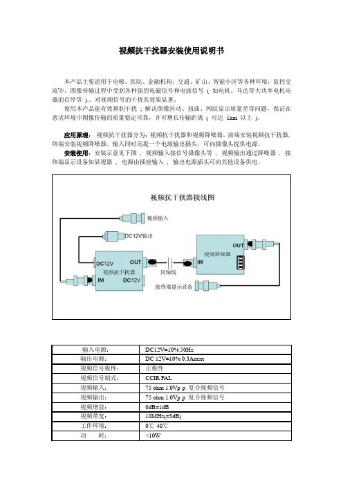
安装使用:安装示意见下图 , 视频输入接信号摄像头等 , 视频输出通过降噪器 . 接终端显示设备如显视器 , 电源由插座输入 , 输出电源插头可向其他设备供电。
输入电源:DC12V±10% 50Hz
输出电源:DC 12V±10% 0.3Amax
视频信号极性:正极性
视频信号制式:CCIR PAL
视频输入:75 ohm 1.0Vp-p 复合视频信号
视频输出:75 ohm 1.0Vp-p 复合视频信号
视频增益:0dB±1dB
视频带宽:10MHz(±3dB)
工作环境:0℃-40℃
功耗:<10W。
安装步骤详解

安装步骤详解在进行任何安装工作之前,正确地了解并遵循安装步骤是至关重要的。
本文将详细介绍一个通用的安装步骤,帮助您更好地理解和执行各种类型的安装工作。
第一步:准备工作在开始安装之前,必须做好充足的准备工作。
这包括:1. 确定安装位置:根据实际需求和安装要求确定最佳的安装位置。
2. 检查设备和材料:确认所有需要的设备和材料齐全,并确保其质量和适用性。
3. 安全措施:了解和采取必要的安全措施,以保护人员和设备安全。
第二步:安装准备在进行实际安装之前,需要进行一些准备工作:1. 解包和排列:打开设备包装,将设备和材料按照安装顺序排列整齐。
2. 阅读说明:仔细阅读安装说明和相关文档,确保理解每个步骤和要求。
3. 工具准备:准备好所需的工具,以便在安装过程中使用。
第三步:实际安装在进行实际安装时,请遵循以下步骤:1. 组件安装:按照说明书的要求,将设备的各个组件进行正确的安装和连接。
2. 连接和布线:根据安装要求,连接设备和布线,确保所有的连接都牢固可靠。
3. 调整和校准:根据设备的要求,进行必要的调整和校准,以确保设备的正常运行。
第四步:测试和验证在完成实际安装后,需要进行一些测试和验证工作,以确保设备正常工作:1. 设备测试:对设备进行必要的测试,检查其各项功能是否正常。
2. 效果验证:验证设备的安装效果是否符合预期,是否满足所需的要求。
3. 故障排除:如有问题或故障出现,在设备安装过程中进行必要的排除和修复。
第五步:清理和整理在完成安装工作后,需要进行清理和整理,将工作区域恢复到原始的整洁状态:1. 清理垃圾:将所有的包装材料、废弃物和不需要的材料清理干净,妥善处理。
2. 工具归位:将使用过的工具和材料放回原处,确保工作区整洁有序。
3. 检查核对:再次检查设备安装是否完整,确认一切都按照步骤进行。
总结:安装步骤详解了一个通用的安装过程。
在进行任何类型的安装之前,确保做好充足的准备工作,并严格按照步骤进行安装,以确保安装的顺利进行和设备的正常运行。
办公系统客户端安装插件使用说明
办公系统客户端安装插件使用说明
一、安装插件:
1.打开办公系统客户端,在主界面上选择“设置”选项。
2.在设置页面中,找到“插件管理”选项并点击进入。
3.在插件管理页面上,用户可以看到已安装的插件和未安装的插件列表。
4.在未安装的插件列表中,找到要安装的插件,并点击插件名称旁边
的“安装”按钮。
5.安装过程可能需要几秒钟的时间,请耐心等待,直到插件安装完成。
6.安装完成后,用户可以在已安装的插件列表中找到刚刚安装的插件,并可以通过开关按钮进行启用或禁用。
二、使用插件:
1.打开办公系统客户端,在主界面上选择“插件”选项。
2.在插件页面上,用户可以看到已启用的插件列表。
3.点击已启用的插件名称,即可进入插件的功能界面。
4.根据插件的具体功能,用户可以进行相应的操作,如上传文件、查
看日历、发送邮件等。
5.用户也可以在插件的功能界面上进行插件的设置,如调整插件的显
示方式、修改插件的参数等。
三、更新插件:
1.打开办公系统客户端,在主界面上选择“设置”选项。
2.在设置页面中,找到“插件管理”选项并点击进入。
3.在插件管理页面上,用户可以看到已安装的插件和未安装的插件列表。
4.在已安装的插件列表中,如果有新版本的插件可用,会在插件名称旁边显示一个“更新”按钮。
6.安装完成后,用户可以在已安装的插件列表中找到更新后的插件,并可以通过开关按钮进行启用或禁用。
总结:。
软件安装说明书
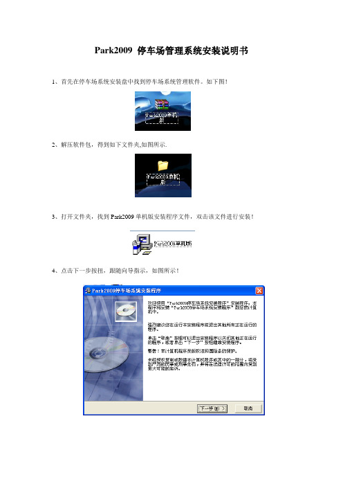
Park2009 停车场管理系统安装说明书1、首先在停车场系统安装盘中找到停车场系统管理软件。
如下图!
2、解压软件包,得到如下文件夹,如图所示.
3、打开文件夹,找到Park2009单机版安装程序文件,双击该文件进行安装!
4、点击下一步按扭,跟随向导指示,如图所示!
5、停车场系统默认安装在D:\Park2009 文件夹中,如有其它情况,请点击浏览按扭,选择自已需要的安装位置。
6、点击下一步按扭,开始开装!
软件正在安装。
软件安装完毕。
停车场管理的基本设置
1、启动软件:软件在电脑桌面上安装好有停车场管理系统的图标!
2、双击后,如下图所
2、弹出密码输入框
3、输入验证码是否正有问题的。
软件初始密码是‘123’
4、进入程序主界面。
XGN80-40.5安装使用说明书
1.2 标准及规范
开关柜满足以下标准:
* GB 1984
高压交流断路器
* GB 3906
3.6~40.5kV 交流金属封闭开关设备和控制设备
* GB/T 11022 高压开关设备通用技术条件
* DL/T 791
户内交流充气式开关柜选用导则
* IEC 62271-1 高压开关设备和控制设备-第 1 部分:共用技术要求
器气室和母线气室)、带操动机构的插入式断路器。
开关柜的气室外壳采用 3mm 不锈钢板,通过三维激 光 焊 机 焊 接 成 相 互 独 立 的 密 封
气室,气箱内面焊有加强筋,保证在高海拔地区气箱的变形在允许范围内。静态密封采用
三元乙丙 O 型圈,动态密封采用波纹管和磁流体,通过以上措施来保证气箱极低的漏气率。
3.2 开关柜绝缘气体系统
高压带电部件安装于充气的封闭气室内,完全不受外界大气条件的影响。 * 每台开关柜的断路器气室及母线气室均为独立气室,均有独立的气体系统。柜间气室
也相互独立。 * 气室内配袋装干燥剂。
运行压力检测: * 开关柜每个独立气室的额定充气压力由独立的密度控制器(图 3-2)进行监测。 --断路器气室的密度控制器 --母线气室的密度控制器 * 密度控制器,具有环境温度补偿功能。 * 气体额定工作压力为 0.05MPa(相对压力),当低于 0.03MPa(相对压力)时,智能控
1.3 运行条件
* 环境温度不高于+40℃,不低于-25℃; * 相对湿度:日平均值不大于 95%,月平均值不大于 90%; * 海拔高度不大于 5000m; * 地震烈度不超过 8 度; * 无火灾爆炸、严重污秽、化学腐蚀及剧烈震动的场所; 注:特殊环境条件请咨询制造商。
安装使用说明书
1.适用全热交换器型号RS485设备型号:FY-RS15ZDP2C■请妥善保管好此安装使用说明书以备日后参考。
(保留备用)安装使用说明书2.包装附件清单官方微信服务号■家用薄型全热交换器■商用全热交换器FY-15ZDP1C FY-25ZDP1C FY-35ZDP1C FY-50ZDP1CFY-15GZD1FY-25GZD1FY-35GZD1FY-50GZD1FY-RZ18DP1FY-RZ28DP1FY-15ZY1C FY-25ZY1C FY-35ZY1C FY-50ZY1C FY-65ZY1C FY-80ZY1CFY-1KZY1C FY-1HZY1C FY-2KZY1C■家用薄型全热交换器(适用寒冷地区)FY-15ZDP1CX FY-25ZDP1CX FY-35ZDP1CXFY-RZ38DP1■新直流马达全热交换器FY-15ZJD2C FY-25ZJD2C FY-35ZJD2C FY-15GZJP2FY-25GZJP2FY-35GZJP2FY-15ZJP2C FY-25ZJP2C FY-35ZJP2C■全热交换器(柜式新风机)FY-50ZR1CFY-70ZR1C7.寄存器地址一览(该RS485模块通信时使用的寄存器地址如下述一览表所示)8.RS485模块接线图可连续访问复数寄存器地址的范围如下: 读取(功能码:0x03):0x0001~0x0013 写入(功能码:0x10):0x0001~0x0003、0x0011~0x0013、0x0014~0x0017※1 读取时,请使用功能码0x03把复数寄存器地址(0x0011~0x0013)一并读取; 写入时,请使用功能码0x10把复数寄存器地址(0x0011~0x0013)一并写入;(例)「设定定时开 2时50分ON 」、「设定定时关 19时43分ON 」这样设定时(机器地址为0x01)。
01 10 00 11 00 03 06 32 02 01 01 2B 13 C4 03※2 写入时,请使用功能码0x10把复数寄存器地址(0x0014~0x0017)一并写入; (例)「网络时间(17时40分00秒)」这样设定时(机器地址为0x01)。
安装说明书(仅供熟悉和学习用)
安装说明书(仅供熟悉和学习用)首先声明不适用苹果手机,只适合安卓系统手机,不要做侵犯他人隐私等违法用途监控范围:短信,通话记录,通话录音,手机QQ 微信聊天,GPS定位(需要拿到对方手机亲自安装)基本安装思路只有三步:1。
跟安装手机软件游戏一样,将下载的程序安装到手机2。
在手机里打开程序,设置好你的邮箱密码。
3。
测试邮箱,及监控是否正常。
完成后在程序里点隐藏图标(隐藏一定图标一定要在你确保一切正常以后)。
更具体安装说明:安装前准备一个邮箱帐号用来收发监控报告。
(如果是QQ邮箱,需要到邮箱后台设置-帐户最下面打勾POP3/SMTP选项)如果手机有装360卫士需要先到360杀毒-设置-自动联网查杀关了提示:安装后程序有图标,安装测试完后在程序里点隐藏,但不要提前点隐藏。
1。
用91手机助手安装程序到手机或者在手机里直接下载安装到手机。
电脑安装前请选择安装路径到手机内存。
(如果手机安装没有选择,请安装后在设置-应用-所有里找到“系统” 查看是否安装到了内存,如果不是进行移动。
一定要选择安装到内存,否则无法开机自动运行)2。
安装完,桌面里多了个“系统”,直接打开。
设置好邮箱,邮箱密码,点击发送测试邮件看是否成功,是否能收到邮件。
点开启监控,再返回退出。
3。
打电话发短信,每个功能测试一次看能不能收到邮件报告,如果手机有弹出授权之类的都点允许-记住。
4。
重起手机然后进程序看下监控是否打勾,如果打勾说明程序可以正常自动启动,点隐藏图标。
如需重新设置,拨打77886挂断显示图标。
(如果没有自动启动,请查找手机上安全工具的自启管理进行设置)(如果提前隐藏后打77886挂断无法显示图标的话,设置-应用-所有程序里找到系统清除数据卸载重装)(如果打开了防卸载后,要卸载请先到系统设置-安全-设备管理器取消一下系统的打勾)小M手机/Miui系统安装后请在手机进行以下2步:1。
到设置-应用-全部找到“系统”-点权限管理- 点“我信任该程序”跟“自动启动” (或者在安全工具或其它安装的安全软件里)2。
LD9202EN安装使用说明书(2)
第一章 概 述
联动控制盘
LD9202EN 是依据 GB10806-2006 消防规范设计开发的,通过 CAN-BUS 总线 与本公司生产的 EN 系列控制器配套使用,最多可控制 64 路现场设备。对每个 设备既可以多线控制也可总线控制;该盘还具备按键保护、现场信息上传、线 路故障检测以及输出线过流保护等功能。
一路进行数据设置。 设置每一路时所需的信息如下: 盘号(panel_No.):表示该手动盘在该手动报警系统中的编号。此号由手动盘 上的拨码开关确定。拨码开关的第 1-6 位分别表示盘号由低到高的 6 个二进 制位,当拨到“on”位置时表示相应的位为 1,否则为 0。假定用 bit6-bit1 分别表示拨码开关的第 6-1 位的状态,那么手动盘的盘号计算方法应该是: 盘号=32*bit6+16*bit5+8*bit4+4*bit3+2*bit2+bit1 例如下图中:
3.1 结构特征........................................... 1 3.2 工作原理........................................... 2 第四章 技术特性........................................... 2 第五章 安装与调试......................................... 3 5.1 安装说明........................................... 3 5.2 数据设置........................................... 3 5.3 面板信息说明....................................... 5 5.4 8 路多线输出板使用说明 ............................. 6 5.5 调试............................................... 7