Turbo codes
基于Matlab的Turbo码仿真研究

西华大学毕业设计说明书
1 绪论
随着通信技术和计算机技术的迅猛发展,每时每刻都在不断涌现出新的通信和信息 业务,同时各个用户对通信质量和数据传输速率的要求也不尽相同。由于传输信道本身 特有的噪声和衰落的原因,信号到达接收端时难免的会受到干扰而使信号失真。现在一 般采用差错控制码来检查并纠正由信道失真引起的信息传输错误。 由于差错控制码主要 用于实现信道纠错, 所以又称为纠错码。 编译码技术的日益成熟使其应用领域不断扩大, 比如在众多信息交换和存储设备中的广泛应用。 现代信息和编码理论的奠基人 C.E.Shannon 在 1948 年提出了著名的信道编码定理, 在定理中 Shannon 给出了在数字通信系统中实现可靠通信以及在特定信道上实现可靠通 信的信息传输速率上限的方法。Leabharlann 西华大学毕业设计说明书目 录
1 绪论 .................................................................... 1 1.1 数字通信系统的结构 ............................................... 1 1.2 Turbo 码的研究现状 ................................................ 2 1.3 Turbo 码系统仿真模型设计 .......................................... 3 2 Turbo 码的编码 .......................................................... 5 2.1 Turbo 码编码结构 .................................................. 5 2.2 本章小结 ......................................................... 8 3 译码 ................................................................... 9 3.1 Turbo 码的译码结构 ................................................ 9 3.2 基于后验概率的译码算法(MAP 算法) .................................. 9 3.3 MAP 算法的简化算法 ............................................... 13 3.4 迭代译码 ........................................................ 14 3.4.1 算法推导 .................................................. 15 3.4.2 不同迭代次数仿真 .......................................... 16 3.5 本章小结 ........................................................ 18 4 交织器的设计 .......................................................... 19 4.1 交织器的概述 .................................................... 19 4.2 交织器的设计 .................................................... 19 4.2.1 交织器的分析及设计 ........................................ 19 4.2.2 设计过程 .................................................. 20 4.2.3 S-随机交织后输出 .......................................... 22 4.3 本章小结 ........................................................ 23 5 程序设计 .............................................................. 24 5.1 软件介绍 ........................................................ 24 5.2 Turbo 码程序设计流程图: ......................................... 25 5.3 程序仿真及结果分析 .............................................. 27 6 总结与体会 ............................................................ 30 7 致谢 .................................................................. 31 8 参考文献 .............................................................. 32 9 附录:仿真程序 ........................................................ 33
Turbo码讲解
2)。 一般情况下, 这两个分量码编码
器结构相同, 生成序列 Xp1与 Xp2。 为了
提高码率, 序列Xp1与 Xp2需要经过删余
器, 采用删余(puncturing)技术从这两
个校验序列中周期地删除一些校验位,
形成校验位序列 Xp。
第6章 系统分析
• Xp与未编码序列 Xs经过复用调制后, 生成了Turbo码序列 X。 例如, 假定图13 - 2中两个分量编码器的码率均是1/2, 为 了得到1/2码率的Turbo码, 可以采用这 样的删余矩阵: P =[1 0, 0 1], 即删 去来自RSC 1的校验序列 Xp1的偶数位置比 RSC 2的校验序列 Xp2的奇数位 置比特。
• p(s′,
s,
yN1)=p(s′,
yk-11)·p(s,
yk|s′)·p( yNk+1|s)
•
=αk-1(s′)·γk(s′,
(13.3.7)
s)·βk(s)
第6章 系统分析
• 式中:
•
αk(s)≡p(Sk=s, yk1)为前向递推;
•
βk(s)≡p( yNk+1|Sk=s)为后向递推;
•
γk(s′, s)≡p(Sk=s, yk|Sk-1=s′)为s′和s之
间的分支转移概率。
第6章 系统分析
• 下面求αk(s), βk(s)和γk(s′, s)。 由定义得
k (s) p(Sk s, Sk1 s, y1k ) s p(Sk1 s, y1k1) p(Sk s, yk | Sk1 s, y1k1) s (13.3.8)
第6章 系统分析
码 是 码 率 为 1/2 的 寄 存 器 级 数 为 4 的
(2,1,4)RSC码。 其生成矩阵为
Turbo码的误码率值分布评估(IJWMT-V2-N2-8)
Pb
i 1
2k
wi RE erfc( d i c b ) 2k N0
(1)
* Correspoቤተ መጻሕፍቲ ባይዱding author. E-mail address: 67436622@, iewdzhang@
54
Estimate BER Distributions of Turbo Codes
Pb
1 K Es / N 0 N K e A , z e zEs / N0 2 1 K z 1
K N K
(3)
1 2 1 K
z 1
A , z e ( z ) RcEb / N0
Where the is the weight of information and the z is the weight of parity check in a codeword. The summations are extended over all the codewords of a systematic code C. Let ci=(mi0,…,mik-1,pi0,…,pir-1) be a codeword of C, where mii is the ith bit of information and pij is the jth bit in the parity check bits of the codeword ci. Therefore the (3) can be written as
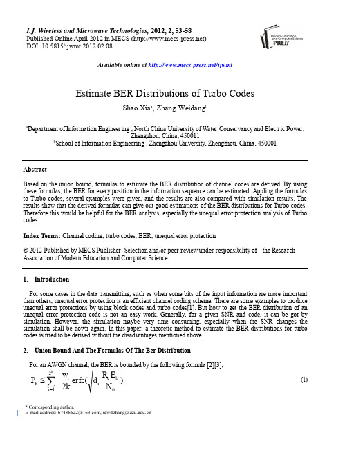
For some cases in the data transmitting, such as when some bits of the input information are more important than others, unequal error protection is an efficient channel coding scheme. There are some examples to produce unequal error protections by using block codes and turbo codes[1]. But how to get the BER distribution of an unequal error protection code is not an easy work. Generally, for a given SNR and code, it can be got by simulation. However, the simulation maybe very time consuming, especially when the SNR changes the simulation shall be down again. In this paper, a theoretic method to estimate the BER distributions for turbo codes is tried to be derived without the disadvantages mentioned above 2. Union Bound And The Formulas Of The Ber Distribution For an AWGN channel, the BER is bounded by the following formula [2][3],
Turbo码及其在无线通信中的应用
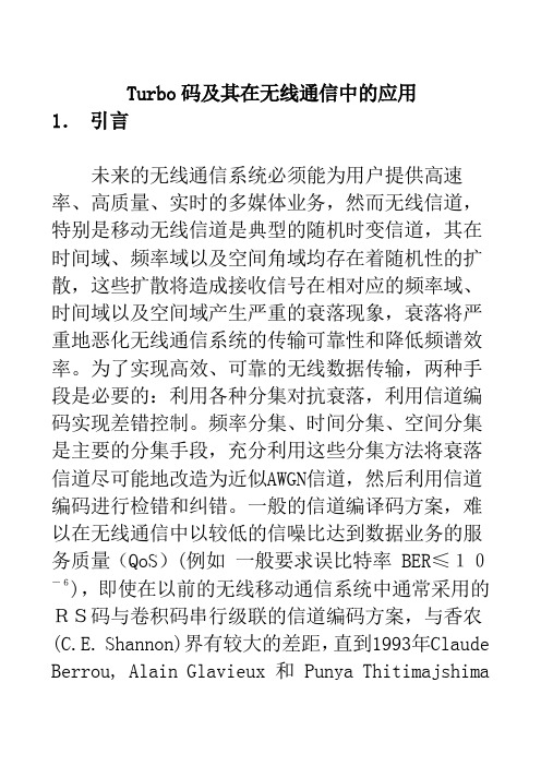
Turbo码及其在无线通信中的应用1.引言未来的无线通信系统必须能为用户提供高速率、高质量、实时的多媒体业务,然而无线信道,特别是移动无线信道是典型的随机时变信道,其在时间域、频率域以及空间角域均存在着随机性的扩散,这些扩散将造成接收信号在相对应的频率域、时间域以及空间域产生严重的衰落现象,衰落将严重地恶化无线通信系统的传输可靠性和降低频谱效率。
为了实现高效、可靠的无线数据传输,两种手段是必要的:利用各种分集对抗衰落,利用信道编码实现差错控制。
频率分集、时间分集、空间分集是主要的分集手段,充分利用这些分集方法将衰落信道尽可能地改造为近似AWGN信道,然后利用信道编码进行检错和纠错。
一般的信道编译码方案,难以在无线通信中以较低的信噪比达到数据业务的服务质量(QoS)(例如一般要求误比特率 BER≤10-6),即使在以前的无线移动通信系统中通常采用的RS码与卷积码串行级联的信道编码方案,与香农(C.E. Shannon)界有较大的差距,直到1993年Claude Berrou, Alain Glavieux 和 Punya Thitimajshima发表他们的著名文章[1],他们发明的Turbo码的性能与香农界的差距仅为0.5dB。
他们发明的Turbo码的创新之处在于:用两个递归系统卷积成员码并行级联编码,这两个系统递归卷积成员码之间用一个伪随机交织器相连接,并且采用软入软出(SISO,Soft-In-Soft-Out)的迭代译码算法。
从此,Turbo 码就成为编码界的一个研究热点。
S. Ten Brink在[2]得到的Turbo码的性能与香农界的差距仅为0.1dB。
2.Turbo码的分类和迭代译码原理现在广义的Turbo码是指采用级联或乘积编码方法并利用迭代译码方法的编译码方案。
迭代译码的基本思想是将一个的复杂的长的译码步骤分解为多个相对简单的迭代译码步骤而且在迭代译码步骤之间信息概率的转移或者是软信息的传递确保几乎没有信息损失。
基于SPIHT图象压缩编码的Turbo codes编码
文章 编 号 :2 327 (O 2 O .220 0 5 .7 8 2 O ) 20 O .8
基于 SI P HT 图 象 压 缩 编 码 的 T r o c d s编 码 u b o e
徐 雯 , 郭 立 , 昌进 刘
( 国科 学技 术大 学 l 中 乜于科 学 技 术 系 , 肥 安 徽 2 o2 ) 台 3 o6
维普资讯
第3 卷 第2 2 期
2002年 4月
中
国
科
学
技
术
大
学
学
报
OO Y LG
V 13 , o2 o.2 பைடு நூலகம் .
A r p .2002
J U N LO HN NV R IYO CI EA D ̄ O R A FC IAU IE ST FS I  ̄C N
0 引 言
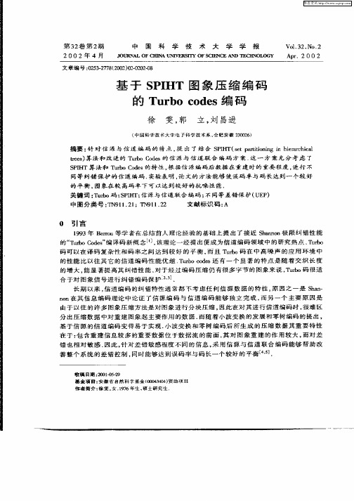
19 9 3年 B r u等 学 者 在 总 结 前 人 理 论 经 验 的基 础 上 提 出 了接 近 S an n极 限 纠 错 性 能 er o hno 的 “ ub o e” 译 码 新 概 念 _ , 理 论 一 经 提 出便 成 为 信 道 编 码 领 域 中 的 研 究 热 点 . ub T roC d s 编 l该 J T ro 码 可 以 在 译 码 复 杂 性 和 码 率 之 间 达 到 较 好 的 平 衡 , 且 T ro码 在 中 高 噪 声 的应 用 环 境 中 而 ub 的 性 能 比 以 往 其 它 的 信 道 编 码 性 能 优 越 T rocd s还 有 一 个 显 著 的 特 点 是 随 着 交 织 长 度 ub o e 的 增 大 , 显 著 提 高 其 纠 错 性 能 . 于 经 过 编 码 压 缩 仍 有很 多 字 节 的 图 象来 说 , ub 能 对 T ro码 很 适 合 于对 图象 信 号 进 行 纠 错 编 码 保 护 . 长 期 以来 , 道 编 码 的纠 错 特 性 通 常 都 不 考 虑 任 何 信 源 数 据 的 特 性 , 因 之 一 是 S a - 信 原 h h
第5章Turbo码,现代编码技术、曾凡鑫

s i 1 (mod K ) , i 1, 2,, N t i 1 / K
(5.1.1)
第5章 Turbo码
Байду номын сангаас
这种安排方式可以这样来理解。将输入序列按行的顺序
填入一个M×K矩阵,式中,N=MK。第一行填满后填第二 行,第二行填满后填第三行,以此类推,形成矩阵:
第5章 Turbo码
图 5.6 一个码率为1/2的SCCC结构Turbo码的编码电路
第5章 Turbo码 表5.3 例5.1.2的外码编码器的编码过程
第5章 Turbo码
(3) 交织器输出。根据题目假设,交织器输出序列为
c(3)=(1010011) (4) 内码编码器输出c(4)。仍然假设编码前内码编码器已 清零,编码后c(4)=(1001010),内码编码器编码过程见表5.4。 (5) 输出码字c。截断复接器将各路输出串接起来形成 SCCC的输出码字c,即
第5章 Turbo码
(5) 删余矩阵删余。从删余矩阵P的结构不难看出,删
余矩阵将删除矢量x1p中偶数位置上的元素,保留奇数位置 上的元素;对x2p则相反,保留偶数位置上的元素,删掉奇 数位置上的元素。于是,删余矩阵输出矢量xp为
1 2 1 2 1 2 x p x1 p , x2 p , x3 p , x4 p , x5 p , x6 p , x1 p 1,1,1,1, 0, 0, 0 7
第5章 Turbo码
图 5.3 一个码率为1/2的PCCC结构Turbo码的编码电路
第5章 Turbo码
解
(1) 矢量xs为
xs=x=(1101010)
(2) 编码器RSC1的输出矢量x1p。 假设编码器RSC1已清零,x1p的产生过程见表5.1,可得 x1p=(1011001)
Turbo-Decoder Quantization for UMTS
Turbo-Decoder Quantization for UMTS Heiko Michel,Student Member,IEEE,and Norbert Wehn,Member,IEEEAbstract—The use of Turbo-Codes is proposed for high-rate data ser-vices in third generation wireless communication systems.Bit-true models are mandatory for hardware and software implementations.In this paper we present to the best of our knowledge thefirst investigation of a combined bit-width optimization of input data and internal data for an8-state Turbo-decoder based on parameters relevant for UMTS.Simulation results for A WGN and Rayleigh-fading channels show that performance degradation can be held below0.11dB using a4-bit input data quantization.Keywords—Quantization,Turbo-Codes,Mobile communicationI.I NTRODUCTIONURBO-CODES are part of the standardization process for third generation wireless communication systems (UMTS).Thus,efficient Turbo-decoder implementations with emphasis on low cost and low energy consumption are of emerg-ing importance.Digital signal processing algorithms like the MAP algorithm used in a Turbo-decoder are usually specified in thefloating-point domain.Fixed-point number representa-tion is mandatory for most target architectures,thus transfor-mation fromfloating tofixed-point is a necessary step towards an actual implementation[1].The resulting bit-true models of the Turbo-decoder may differ for software,hardware and mixed hardware/software target architectures.Primary goal for a soft-ware implementation is tofind afixed-point model that corre-sponds to the given bit-width of the DSP.Further bit-width min-imization can reduce the switching activity and has thus influ-ence on the power consumption.Primary goal for a dedicated hardware implementation is to choose all bit-widths as small as possible,resulting in a reduction of area and energy consump-tion.Hence,an optimized quantization has a large impact on the implementation cost.Only few papers have been published on Turbo-decoder quan-tization.They address input data quantization,assuming infinite accuracy of the internal values[2]or presume a unified quantiza-tion of all signals[3],[4].An8-state Turbo-Code is considered in[5],however not under fading-channel conditions nor with 3GPP compliant interleavers.In[6]we have for thefirst time discussed a systematic approach towards an internal quantiza-tion scheme of a4-state Turbo-decoder with infinite accuracy of the input data.In this paper we present a combined optimization of input data quantization and internal quantization for a3GPP compliant8-state Turbo-decoder.The remainder of this paper is structured as follows:A short review of the system model for the Turbo-decoder is given in Section II.Section III addresses issues of the input data quanti-zation and explains consequences on the quantization model of the MAP algorithm.In Section IV simulation results are pre-sented.Section V concludes this paper.H.Michel and N.Wehn are with the Institute of Microelectronic Sys-tems,University of Kaiserslautern,Kaiserslautern,Germany.E-mail: michel,wehn@eit.uni-kl.de.Fig.1.Turbo-CodeEncoderFig.2.Turbo-decoderII.S YSTEM M ODELIn the following we assume a typical Turbo-encoder with a structure proposed in[7](see Fig.1).It consists of two identical constituent code encoders(RSC1,RSC2),each gen-erating a recursive systematic convolutional code of constraint length using generator polynoms13/15.This con-figuration complies with the3GPP proposal for a code withstates[8].The two encoders are separated by an interleaver(I),which also complies with the3GPP proposal. The parity information(,)and the systematic infor-mation data sequences()are concatenated in parallel,lead-ing to three output bits for each bit of the input data sequence,where is the block size.In a punc-turing and rate matching unit(P)the code rate is adapted.We selected a puncturing scheme which omits every second bit of the parity information,leading to a transmitted data sequenceand a total code rate of.No tailing scheme is implemented. For decoding this Turbo-Code we use the conventional sym-metric decoder structure(see Fig.2),consisting of two maxi-mum a posteriori(MAP1,MAP2)decoders[9],one interleaver (I)and two deinterleavers(D).Each of the MAP decoders cor-responds to one constituent code.The reader is referred to[10] for a more detailed discussion of the MAP algorithm.A short review of the Turbo-decoder implementation,which is relevant in the scope of this paper is given in[6].III.I NPUT Q UANTIZATIONWe have demonstrated in[6]that an optimized quantization scheme of the internal values does not degrade the bit-error per-formance.In this paper,optimized quantization schemes for in-put data and internal values are considered.The notation00.50.50.5 1.0 1.5of the MAP algorithm are calculated as weighted sums of the channel input data and the a priori in-formation([6],eqns.(4),(5))0.000.250.500.75 1.000.250.250.250.250AWGN Rayleigh-fading5Iter.10Iter.5Iter.10Iter.TABLE IIID EGRADATION OF SNR IN OF DIFFERENT QUANTIZATION SCHEMESCOMPARED TO THE REFERENCE FLOATING-POINT MODEL AT,8-STATE T URBO-C ODELog-MAP model is observed in comparison to the reference floating-point model.Reducing the bit-width of the input datato:,almost the same performance is maintained.For ex-ample,at an operating point with degradations of about0.04dB for an AWGN channel and even improvements of up to0.013dB for a Rayleigh-fading channel are observed. With this:quantization scheme the internal quantizationscheme can be reduced to without additional degrada-tion.Implementing the correction term of the Jacobian loga-rithm function(eqn.(3))as a small lookup-table with input and output granularity of(see Table II)comes at no degra-dation of the SNR,but reduces the implementation complexitysignificantly.A further reduction of the input data bit-width to :or:leads to degradations of the SNR,which are shown in Table III for,AWGN/Rayleigh-fading channels and5/10decoding iterations.The corresponding bit-error curves for the3GPP compliant8-state Turbo-decoder aredepicted in Figures3,4,5,and6.Simulation results have shown that for:and:the quantization scheme of the algorithm cannot be further re-duced,according to the granularity of the input data,toor,respectively;the quantization scheme still per-forms best.The increase of granularity within the algorithm is caused by the correction term of Table II.Thus,in order to counteract the degradation caused by the input data quantiza-tion,algorithmic accuracy can be traded to some extent for the accuracy of the input data.This is impossible in the case of a Max-Log-MAP implementation,because of the approximation.The granularity of the algorithm always corresponds to the granularity of the input data;the inter-nal bit-width is therefore further reduced to for:-quantized input data.V.C ONCLUSIONSSeveral quantization schemes for the input data bits have been discussed in combination with internal quantization schemes of an8-state Turbo-decoder,based on parameters relevant forR EFERENCES[1] F.Berens,A.Worm,H.Michel,and N.Wehn,“Implementation Aspectsof Turbo-Decoders for Future Radio Applications,”in Proc.VTC’99Fall, Amsterdam,The Netherlands,Sept.1999,pp.2601–2605.[2]Y.Wu and B.D.Woerner,“The Influence of Quantization and Fixed PointArithmetic upon the BER Performance of Turbo Codes,”in Proc.IEEE International Conference on Vehicular Technology(VTC Spring’99),May 1999,vol.2,pp.1683–1687.[3] D.E.Cress and W.J.Ebel,“Turbo Code Implementation Issues forLow Latency,Low Power Applications,”in Proceedings of1998Symp.Japan,May2000.[7] C.Berrou,A.Glavieux,and P.Thitimajshima,“Near Shannon LimitError-Correcting Coding and Decoding:Turbo-Codes,”in Proc.ICC’93, Geneva,Switzerland,May1993,pp.1064–1070.[8]“Third Generation Partnership Project,”.[9]L.Bahl,J.Cocke,F.Jelinek,and J.Raviv,“Optimal Decoding of LinearCodes for Minimizing Symbol Error Rate,”IEEE Transactions on Infor-mation Theory,vol.IT-20,pp.284–287,Mar.1974.[10]P.Robertson,P.Hoeher,and E.Villebrun,“Optimal and Sub-OptimalMaximum a Posteriori Algorithms Suitable for Turbo Decoding,”ETT, vol.8,no.2,pp.119–125,Mar.–Apr.1997.。
Turbo码算法补充——两种结构
17 18 19 20 21 22 23 24 25 26 27 28 29 30 31 32 33 34 35 36 37 38 39 40 41 42 43 44 45 46 47
168 176 184 192 200 208 216 224 232 240 248 256 264 272 280 288 296 304 312 320 328 336 344 352 360 368 376 384 392 400 408
101 21 57 23 13 27 11 27 85 29 33 15 17 33 103 19 19 37 19 21 21 115 193 21 133 81 45 23 243 151 155
84 44 46 48 50 52 36 56 58 60 62 32 198 68 210 36 74 76 78 120 82 84 86 44 90 46 94 48 98 40 102
三、仿真结果
1. 不同译码算法间的误码率比较, 交织深度 500, 迭代次数为 10, 采用 3GPP 标准结构:
10
-1
误码率曲线 map算 法 logmap算 法 maxlogmap算 法
10
-2
10
BER
-3
10
-4
10
-5
10
-6
0
0.2
0.4
0.6 0.8 Eb/N0(dB)
1
1.2
1.4
10
-1
误码率曲线 交 织 深 度 500 交 织 深 度 1000 交 织 深 度 4000 吴 宇 飞 交 织 深 度 4000
10
-2
10
-3
BER
10
New Classes of Algebraic Interleavers for Turbo-Codes 1
We thus have a second class of interleavers that we call DN :C2 . Decoders for turbo-codes need interleaver-deinterleaver pairs. The DN :C2 interleavers provide an interesting implementation advantage, since deinterleaving is identical to interleaving.
1e+00 <R 128>7 D 128:CN|k=1,h=0 D 128:C2|k=1,h=N/2 <R 256>7 D 256:CN|k=1,h=0 D 256:C2|k=1,h=N/2 <R 512>7 D 512:CN|k=1,h=0 D 512:C2|k=1,h=N/2 <R 1024>7 D 1024:CN|k=1,h=0 D 1024:C2|k=1,h=N/2 <R 16384>7 D 16384:CN|k=1,h=0 D 16384:C2|k=1,h=N/2 1e-01
1e-02
1e-03 BER 1e-04 1e-05 1e-06 1e-07 -0.5 0 0.5 1 1.5 Eb/No 2
2.5
3
3.5
Fig. 1: Simulation results for the new DN :CN and DN :C 2 interleavers for lengths 128, 256, 512, 1024, and 16384 compared with the average performance of 7 random RN 7 interleavers with the same respective lengths.
Compression withSide Information usingTurbo Codes
• Objective
– Design practical codes which achieve compression close to the Slepian-Wolf bound
Compression with Side Information Using Turbo Codes
April 3, 2002
Asymmetric Scenario – Compression with Side Information
RX ≥ H ( X | Y )
Decoder
X
Statistically dependent
Encoder
X ′, Y ′
Y
RY = H (Y )
RX + RY ≥ H ( X , Y )
Joint Source-Channel Coding
• Assume that the parity bits pass through a memoryless channel with capacity C • We can include the channel statistics in the decoder calculations for Pchannel. • From Slepian-Wolf theorem and definition of Channel capacity
Slepian-Wolf Theorem
RX ≥ H ( X | Y ) RY ≥ H (Y | X )
Compression with Side Information Using Turbo Codes
April 3, 2002
Research Problem
• Motivation
- 1、下载文档前请自行甄别文档内容的完整性,平台不提供额外的编辑、内容补充、找答案等附加服务。
- 2、"仅部分预览"的文档,不可在线预览部分如存在完整性等问题,可反馈申请退款(可完整预览的文档不适用该条件!)。
- 3、如文档侵犯您的权益,请联系客服反馈,我们会尽快为您处理(人工客服工作时间:9:00-18:30)。
Code rate
• The two encoders have code rates R1and R2 respectively ,and the overall code rate R of the turbo encoder is given by:
R R1R 2 R1 R 2 R1 R 2
Turbo decoder
• Turbo decoder 系統是由兩個SISO decoders、一個交錯器、 一個解交錯器以及一個Hard decision device組合而成
Turbo decoder
• 編碼的資料經過AWGN,接受後資料算成LLR值後在拆成 三路為y0,y1,y2,分別對應V0,V1,V2,之後再將此3個值送 到SISO做解碼
遞迴迴旋編碼(RSC)
遞迴迴旋編碼(RSC)
1. 首先讓位移暫存器D1、D2為零 d
2. 之後資料輸入 a d x
D1 D 2
3. 得到a之後計算v1 V1 a D 2
4. V1即為此刻的編碼資料 5. D1存到D2,a存到D1
ห้องสมุดไป่ตู้
遞迴迴旋編碼(RSC)
X 1 0 d 0 1 a 1 1 D1 0 1 D2 0 0 V1 1 1
1
0 1
0
0 1
1
0 0
1
1 0
1
1 1
0
1 1
• V0 = [1 0 1 0 1],V1 = [1 1 0 1 1] • V = [1 1 , 0 1 , 1 0 , 0 1 , 1 1] 為最終編碼資料
交錯器(interleaver)
• 目的是將一串連續位元原本的順序重新排列,使得傳送的 位元遇到叢發性錯誤(burst error),也不會因為兩個RSC之間 的位元相關性太強,而無法更正錯誤
Turbo codes
Turbo codes 的介紹與性能分析
• Turbo codes 主要是由兩個相同的遞迴迴旋編碼RSC (recursive systematic convolution encoder)和一個交錯器 (interleaver)所構成 • 交錯器放置在第二個編碼器的前端,目的在將原來的訊號 順序打亂 • Turbo codes 利用反覆解碼(iteration)的技巧可以降低系統錯 誤率
2
2
yk
Interative decoding
• 在第一次疊代時,第一個SISO的輸入為y0,y1,經過MAP 演算法後輸出,經過重排後,變成第二個SISO中的事前資 訊,增進解碼的可靠度,之後輸出又迴授到第一個解碼器 的輸入端。如此反覆疊代,讓每一次解碼都利用上一次的 結果,使的解碼器的正確性越高
LLR(log-likelihood ratio)
• 計算而得的LLR值由下列公式得到 • Uk為傳送的訊號 • yk為經過AWGN後接收的訊號
p y k u k 1 L y k log e p y k u k 1 1 exp 2 log e 1 exp 2 2 2 1 yk 1 2 1 yk 1 2