3 MS for block wall works at KLSSv.2
5层框架结构教学楼结构标准计算书
1#教学楼部分///////////////////////////////////////////////////////////////////////////| 公司名称: || || 建筑结构的总信息|| SATWE2010_V4.3.4 中文版|| (2019年4月15日9时13分) | | 文件名: WMASS.OUT | | ||工程名称: 设计人: | |工程代号: 校核人: | ///////////////////////////////////////////////////////////////////////////总信息 ..............................................结构材料信息: 钢砼结构混凝土容重(kN/m3): Gc = 26.00钢材容重(kN/m3): Gs = 78.00是否扣除构件重叠质量和重量: 是是否自动计算现浇楼板自重: 是水平力的夹角(Degree): ARF = 0.00地下室层数: MBASE = 1竖向荷载计算信息: 按模拟施工3加荷计算风荷载计算信息: 计算X,Y两个方向的风荷载地震力计算信息: 计算X,Y两个方向的地震力“规定水平力”计算方法: 楼层剪力差方法(规范方法)结构类别: 框架结构裙房层数: MANNEX = 0转换层所在层号: MCHANGE= 0嵌固端所在层号: MQIANGU= 1墙元细分最大控制长度(m): DMAX = 1.00弹性板细分最大控制长度(m): DMAX_S = 1.00是否对全楼强制采用刚性楼板假定: 否(整体指标结果采用强刚,其他结果采用非强刚)墙梁跨中节点作为刚性楼板的从节点: 是墙倾覆力矩的计算方法: 考虑墙的所有内力贡献墙偏心的处理方式: 传统移动节点方式高位转换结构等效侧向刚度比采用高规附录E: 否是否梁板顶面对齐: 否是否带楼梯计算: 否框架连梁按壳元计算控制跨高比: 0.00墙梁转框架梁的控制跨高比: 0.00结构所在地区: 全国楼板按有限元方式进行面外设计否多模型及包络........................................采用指定的刚重比计算模型:否计算控制信息 ..........................................计算软件信息: 64位线性方程组解法: PARDISO地震作用分析方法: 总刚分析方法位移输出方式: 简单输出是否生成传基础刚度: 否保留分析模型上自定义的风荷载: 否采用自定义范围统计指标: 否高级参数............................................位移指标统计时考虑斜柱:否采用自定义位移指标统计节点范围:否按框架梁建模的连梁砼等级默认同墙:否二道防线调整时,调整与框架柱相连的框架梁端弯矩、剪力:是薄弱层地震内力调整时不放大构件轴力:否剪切刚度计算时考虑柱刚域影响:否短肢墙判断时考虑相连墙肢厚度影响:否刚重比验算考虑填充墙刚度影响:否剪力墙端柱的面外剪力统计到框架部分:否风荷载信息 ..........................................修正后的基本风压(kN/m2): WO = 0.30 风荷载作用下舒适度验算风压(kN/m2): WOC = 0.10 地面粗糙程度: B 类结构X向基本周期(秒): Tx = 1.40 结构Y向基本周期(秒): Ty = 1.50 是否考虑顺风向风振: 是风荷载作用下结构的阻尼比(%): WDAMP = 5.00 风荷载作用下舒适度验算阻尼比(%): WDAMPC = 2.00 是否计算横风向风振: 否是否计算扭转风振: 否承载力设计时风荷载效应放大系数: WENL = 1.00 体形变化分段数: MPART = 1 各段最高层号: NSTI = 8 各段体形系数(X): USIX = 1.50各段体形系数(Y): USIY = 1.50设缝多塔背风面体型系数: USB = 0.50地震信息 ............................................结构规则性信息: 不规则振型组合方法(CQC耦联;SRSS非耦联): CQC特征值分析方法: 子空间迭代法是否由程序自动确定振型数: 否计算振型数: NMODE = 15 地震烈度: NAF = 6.00 场地类别: KD =II设计地震分组: 一组特征周期: TG = 0.35 地震影响系数最大值: Rmax1 = 0.04 用于12层以下规则砼框架结构薄弱层验算的地震影响系数最大值: Rmax2 = 0.28 框架的抗震等级: NF = 2 剪力墙的抗震等级: NW = 3 钢框架的抗震等级: NS = 3 抗震构造措施的抗震等级: NGZDJ =不改变悬挑梁默认取框架梁抗震等级: 否按抗规(6.1.3-3)降低嵌固端以下抗震构造措施的抗震等级: 是重力荷载代表值的活载组合值系数: RMC = 0.50 周期折减系数: TC = 0.70 结构的阻尼比(%): DAMP = 5.00 是否考虑偶然偏心: 是偶然偏心考虑方式: 相对于投影长度X向相对偶然偏心: ECCEN_X= 0.05 Y向相对偶然偏心: ECCEN_Y= 0.05 是否考虑双向地震扭转效应: 是是否考虑最不利方向水平地震作用: 是按主振型确定地震内力符号: 否斜交抗侧力构件方向的附加地震数: NADDDIR= 0 工业设备的反应谱方法底部剪力占规范简化方法底部剪力的最小比例: SeisCoef= 1.00活荷载信息 ..........................................考虑活荷不利布置的层数: 不考虑考虑结构使用年限的活荷载调整系数: FACLD = 1.00 考虑楼面活荷载折减方式:传统方式柱、墙活荷载是否折减: 折减传到基础的活荷载是否折减: 折减柱,墙,基础活荷载折减系数:计算截面以上的层数折减系数1 1.002---3 0.854---5 0.706---8 0.659---20 0.60> 20 0.55梁楼面活荷载折减设置: 不折减墙、柱设计时消防车荷载是否考虑折减:是柱、墙设计时消防车荷载折减系数: 1.00梁设计时消防车荷载是否考虑折减:是调整信息 ........................................楼板作为翼缘对梁刚度的影响方式: 梁刚度放大系数由用户指定中梁刚度放大系数: BK = 2.00托墙梁刚度放大系数: BK_TQL = 1.00梁端负弯矩调幅系数: BT = 0.85梁端弯矩调幅方法: 通过竖向构件判断调幅梁支座梁活荷载内力放大系数: BM = 1.10梁扭矩折减系数: TB = 0.40支撑按柱设计临界角度(Deg): ABr2Col= 20.00地震工况连梁刚度折减系数: BLZ = 0.70风荷载工况连梁刚度折减系数: BLZW = 1.00采用SAUSAGE-CHK计算的连梁刚度折减系数:否地震位移计算不考虑连梁刚度折减:否柱实配钢筋超配系数: CPCOEF91 = 1.15墙实配钢筋超配系数: CPCOEF91_W = 1.15全楼地震力放大系数: RSF = 1.000.2Vo 调整方式: alpha*Vo和beta*Vmax两者取小0.2Vo 调整中Vo的系数: alpha = 0.200.2Vo 调整中Vmax的系数: beta = 1.500.2Vo 调整分段数: VSEG = 00.2Vo 调整上限: KQ_L = 2.00是否调整与框支柱相连的梁内力: 否框支柱调整上限: KZZ_L = 5.00框支剪力墙结构底部加强区剪力墙抗震等级自动提高一级: 是是否按抗震规范5.2.5调整楼层地震力: 是是否扭转效应明显: 否是否采用自定义楼层最小剪力系数: 否弱轴方向的动位移比例因子: XI1 = 0.50强轴方向的动位移比例因子: XI2 = 0.50薄弱层判断方式: 按高规和抗规从严判断受剪承载力薄弱层是否自动调整: 否判断薄弱层所采用的楼层刚度算法: 地震剪力比地震层间位移算法强制指定的薄弱层个数: NWEAK = 0薄弱层地震内力放大系数: WEAKCOEF = 1.25强制指定的加强层个数: NSTREN = 0钢管束墙混凝土刚度折减系数: GGSH_CONC = 1.00转换结构构件(三、四级)的水平地震作用效应放大系数: 1.00配筋信息 ........................................梁主筋强度(N/mm2): IB = 360 梁箍筋强度(N/mm2): JB = 270 柱主筋强度(N/mm2): IC = 360 柱箍筋强度(N/mm2): JC = 270 墙主筋强度(N/mm2): IW = 360 墙水平分布筋强度(N/mm2): FYH = 360 墙竖向分布筋强度(N/mm2): FYW = 300 边缘构件箍筋强度(N/mm2): JWB = 270 梁箍筋最大间距(mm): SB = 100.00 柱箍筋最大间距(mm): SC = 100.00 墙水平分布筋最大间距(mm): SWH = 150.00 墙竖向分布筋配筋率(%): RWV = 0.15 墙最小水平分布筋配筋率(%): RWHMIN = 0.00梁抗剪配筋采用交叉斜筋时,箍筋与对角斜筋的配筋强度比: RGX = 1.00设计信息 ........................................结构重要性系数: RWO = 1.00 钢柱计算长度计算原则(X向/Y向): 有侧移/有侧移梁端在梁柱重叠部分简化: 不作为刚域柱端在梁柱重叠部分简化: 不作为刚域是否考虑钢梁刚域:否结构内力分析方法: 一阶弹性设计方法考虑P-DELTA效应方法: 不考虑是否考虑结构整体缺陷: 否是否考虑结构构件缺陷: 否柱计算长度系数是否置为1 : 否柱长细比执行《高钢规》JGJ 99-2015第7.3.9条:否柱配筋计算原则: 按单偏压计算柱双偏压配筋方式:普通方式钢构件截面净毛面积比: RN = 0.85 梁按压弯计算的最小轴压比: UcMinB = 0.40 梁保护层厚度(mm): BCB = 20.00 柱保护层厚度(mm): ACA = 20.00 剪力墙构造边缘构件的设计执行高规7.2.16-4: 否框架梁端配筋考虑受压钢筋: 是结构中的框架部分轴压比限值按纯框架结构的规定采用: 否当边缘构件轴压比小于抗规6.4.5条规定的限值时一律设置构造边缘构件: 是是否按混凝土规范B.0.4考虑柱二阶效应: 否执行高规5.2.3-4条主梁弯矩按整跨计算: 是执行高规5.2.3-4条的梁对象: 仅主梁执行柱剪跨比计算原则: 简化方式过渡层个数0轴压比计算考虑活荷载折减:是墙柱配筋采用考虑翼缘共同工作的设计方法:否执行《混规》第9.2.6.1条有关规定:是执行《混规》第11.3.7条有关规定:是圆钢管混凝土构件设计执行规范:高规(JGJ-2010)方钢管混凝土构件设计执行规范:矩形钢管砼规程(CECS 159:2004)型钢混凝土构件设计执行规范:型钢砼组合结构规程(JGJ 138-2001)异形柱设计执行规范:混凝土异形柱结构技术规程(JGJ 149-2006)钢结构设计执行规范:钢结构设计规范(GB50017-2003)荷载组合信息 ........................................地震与风同时组合:是屋面活荷载是否与雪荷载和风荷载同时组合:是考虑竖向地震为主的组合:否普通风与特殊风是否同时进行组合: 否自动添加自定义工况组合: 是自定义工况组合方式叠加恒载分项系数: CDEAD = 1.30活载分项系数: CLIVE = 1.50风荷载分项系数: CWIND = 1.50水平地震力分项系数: CEA_H = 1.30竖向地震力分项系数: CEA_V = 0.50温度荷载分项系数: CTEMP = 1.40吊车荷载分项系数: CCRAN = 1.40特殊风荷载分项系数: CSPW = 1.40活荷载的组合值系数: CD_L = 0.70风荷载的组合值系数: CD_W = 0.60重力荷载代表值效应的活荷组合值系数: CEA_L = 0.50重力荷载代表值效应的吊车荷载组合值系数:CEA_C = 0.00吊车荷载组合值系数: CD_C = 0.70温度作用的组合值系数:仅考虑恒载、活载参与组合: CD_TDL = 0.60考虑风荷载参与组合: CD_TW = 0.00考虑地震作用参与组合: CD_TE = 0.00砼构件温度效应折减系数: CC_T = 0.30是否计算吊车荷载: 否地下信息 ..........................................室外地面相对于结构底层底部的高度(m): Hsoil = 0.00土的X向水平抗力系数的比例系数(MN/m4): MX = 0.00土的Y向水平抗力系数的比例系数(MN/m4): MY = 0.00地面处回填土X向刚度折减系数: RKX = 0.00地面处回填土Y向刚度折减系数: RKY = 0.00回填土容重(kN/m3): Gsol = 18.00回填土侧压力系数: Rsol = 0.50外墙分布筋保护厚度(mm): WCW = 35.00室外地平标高(m): Hout = -0.35地下水位标高(m): Hwat = -20.00室外地面附加荷载(kN/m2): Qgrd = 0.00面外设计方法: SATWE传统方法水土侧压计算: 水土合算外侧纵筋保护层厚度(mm):35.00内侧纵筋保护层厚度(mm):35.00性能设计信息 ........................................按照全国高规进行性能设计: 否剪力墙底部加强区的层和塔信息.......................层号塔号1 12 13 1用户指定薄弱层的层和塔信息.........................层号塔号用户指定加强层的层和塔信息.........................层号塔号约束边缘构件与过渡层的层和塔信息...................层号塔号类别1 1 约束边缘构件层2 1 约束边缘构件层3 1 约束边缘构件层4 1 约束边缘构件层********************************************************** 各层的质量、质心坐标信息**********************************************************层号塔号质心X 质心Y 质心Z 恒载质量活载质量附加质量质量比(m) (m) (t) (t)8 1 70.594 58.550 34.800 684.8 14.3 0.0 0.447 1 71.456 57.113 30.900 1451.2 133.6 0.0 0.926 1 71.445 56.374 27.000 1540.7 181.2 0.0 1.005 1 71.451 56.359 23.100 1547.4 178.4 0.0 1.004 1 71.451 56.359 19.200 1547.4 178.4 0.0 1.003 1 71.448 56.363 15.300 1551.7 178.4 0.0 0.212 1 80.768 67.104 11.300 7185.5 1253.50.0 2.47(>1.5不满足高规3.5.6条)1 1 75.530 63.720 4.000 2916.5 504.8 0.0 1.00活载产生的总质量(t): 2622.502恒载产生的总质量(t): 18425.279附加总质量(t): 0.000结构的总质量(t): 21047.781恒载产生的总质量包括结构自重和外加恒载结构的总质量包括恒载产生的质量和活载产生的质量和附加质量活载产生的总质量和结构的总质量是活载折减后的结果(1t = 1000kg)********************************************************** 各层构件数量、构件材料和层高**********************************************************层号(标准层号) 塔号梁元数柱元数墙元数层高累计高度(混凝土/主筋/箍筋) (混凝土/主筋/箍筋) (混凝土/主筋/水平筋/竖向筋) (m) (m)1( 2) 1 239( 35/ 360/ 270) 66( 40/ 360/ 270) 14( 40/ 360/ 360/ 300) 4.000 4.0002( 3) 1 711( 35/ 360/ 270) 66( 40/ 360/ 270) 0( 40/ 360/ 360/ 300) 7.300 11.3003( 4) 1 319( 30/ 360/ 270) 41( 40/ 360/ 270) 0( 30/ 360/ 360/ 300) 4.000 15.3004( 4) 1 319( 30/ 360/ 270) 41( 30/ 360/ 270) 0( 30/ 360/ 360/ 300) 3.900 19.2005( 4) 1 319( 30/ 360/ 270) 41( 30/ 360/ 270) 0( 30/ 360/ 360/ 300) 3.900 23.1006( 5) 1 319( 30/ 360/ 270) 41( 30/ 360/ 270) 0( 30/ 360/ 360/ 300) 3.900 27.0007( 6) 1 227( 30/ 360/ 270) 41( 30/ 360/ 270) 0( 30/ 360/ 360/ 300) 3.900 30.9008( 7) 1 217( 30/ 360/ 270) 40( 30/ 360/ 270) 0( 30/ 360/ 360/ 300) 3.900 34.800********************************************************** 风荷载信息**********************************************************层号塔号风荷载X 剪力X 倾覆弯矩X 风荷载Y 剪力Y 倾覆弯矩Y8 1 159.94 159.9 623.8 259.16 259.2 1010.77 1 147.70 307.6 1823.6 239.62 498.8 2955.96 1 135.71 443.4 3552.7 224.67 723.4 5777.45 1 123.19 566.5 5762.2 204.95 928.4 9398.24 1 110.70 677.2 8403.5 184.43 1112.8 13738.23 1 99.68 776.9 11511.2 166.32 1279.2 18854.82 1 163.92 940.8 18379.3 268.41 1547.6 30152.11 1 0.00 940.8 22142.7 0.00 1547.6 36342.3=========================================================== ================各楼层偶然偏心信息=========================================================== ================层号塔号X向偏心Y向偏心1 1 0.050 0.0502 1 0.050 0.0503 1 0.050 0.0504 1 0.050 0.0505 1 0.050 0.0506 1 0.050 0.0507 1 0.050 0.0508 1 0.050 0.050===========================================================各楼层等效尺寸(单位:m,m**2)=========================================================== ================层号塔号面积形心X 形心Y 等效宽B 等效高H 最大宽BMAX 最小宽BMIN1 1 2496.20 77.11 63.44 63.97 38.80 64.01 38.732 1 2496.04 77.11 63.44 63.96 38.80 64.01 38.733 1 1178.63 72.26 56.12 59.49 34.75 60.77 32.464 1 1178.63 72.26 56.12 59.49 34.75 60.77 32.465 1 1178.63 72.26 56.12 59.49 34.75 60.77 32.466 1 1178.63 72.26 56.12 59.49 34.75 60.77 32.467 1 1173.95 72.11 56.13 59.04 34.82 60.35 32.498 1 1152.50 72.32 55.56 59.33 32.65 60.29 30.83=========================================================== ================各楼层的单位面积质量分布(单位:kg/m**2)=========================================================== ================层号塔号单位面积质量g[i] 质量比max(g[i]/g[i-1],g[i]/g[i+1])1 1 1370.62 1.002 1 3380.95 2.473 1 1467.85 1.004 1 1464.28 1.005 1 1464.28 1.006 1 1460.93 1.087 1 1349.95 2.238 1 606.54 1.00=========================================================== ================计算信息===========================================================工程文件名: 1#教学楼计算日期: 2021. 2.23开始时间: 17:50:33机器内存: 16335.0MB可用内存: 8513.0MB结构总出口自由度为: 5511结构总自由度为: 6303第一步: 数据预处理第二步: 计算结构质量、刚度、刚心等信息第三步: 结构整体有限元分析*结构有限元分析: 地震工况*结构有限元分析: 一般工况第四步: 计算构件内力结束日期: 2021. 2.23结束时间: 17:51: 5总用时: 0: 0:32=========================================================== ================各层刚心、偏心率、相邻层侧移刚度比等计算信息Floor No : 层号Tower No : 塔号Xstif,Ystif : 刚心的X,Y 坐标值Alf : 层刚性主轴的方向Xmass,Ymass : 质心的X,Y 坐标值Gmass : 总质量Eex,Eey : X,Y 方向的偏心率Ratx,Raty : X,Y 方向本层塔侧移刚度与下一层相应塔侧移刚度的比值(剪切刚度) Ratx1,Raty1 : X,Y 方向本层塔侧移刚度与上一层相应塔侧移刚度70%的比值或上三层平均侧移刚度80%的比值中之较小者(《抗规》刚度比)Ratx2,Raty2 : X,Y 方向的刚度比,对于非广东地区分框架结构和非框架结构,框架结构刚度比与《抗规》类似,非框架结构为考虑层高修正的刚度比;对于广东地区为考虑层高修正的刚度比(《高规》刚度比)RJX1,RJY1,RJZ1: 结构总体坐标系中塔的侧移刚度和扭转刚度(剪切刚度)RJX3,RJY3,RJZ3: 结构总体坐标系中塔的侧移刚度和扭转刚度(地震剪力与地震层间位移的比)=========================================================== ================注意:本文件输出的刚度比等信息均为非强刚模型下的结果,强刚模型下的结果请到《$强刚》文件夹或新版计算书中查看Floor No. 1 Tower No. 1Xstif= 49.5618(m) Ystif= 78.1132(m) Alf = 17.4688(Degree) Xmass= 75.5304(m) Ymass= 63.7205(m) Gmass(活荷折减)= 3926.1431( 3421.3252)(t)Eex = 1.8263 Eey = 1.0995Ratx = 1.0000 Raty = 1.0000Ratx1= 11.9403 Raty1= 7.5023Ratx2= 11.9403 Raty2= 7.5023 薄弱层地震剪力放大系数= 1.00RJX1 = 3.7843E+07(kN/m) RJY1 = 4.5143E+07(kN/m) RJZ1 = 0.0000E+00(kN/m)RJX3 = 8.2701E+06(kN/m) RJY3 = 4.3588E+06(kN/m) RJZ3 = 0.0000E+00(kN/m)RJX3*H = 3.3080E+07(kN) RJY3*H = 1.7435E+07(kN) RJZ3*H = 0.0000E+00(kN)--------------------------------------------------------------------------- Floor No. 2 Tower No. 1Xstif= 74.5833(m) Ystif= 64.3670(m) Alf = 0.0000(Degree) Xmass= 80.7675(m) Ymass= 67.1040(m) Gmass(活荷折减)= 9692.4492( 8438.9766)(t)Eex = 0.2847 Eey = 0.1144Ratx = 0.0283 Raty = 0.0192Ratx1= 0.8330 Raty1= 0.8362Ratx2= 0.8330 Raty2= 0.8362 薄弱层地震剪力放大系数= 1.25RJX1 = 1.0714E+06(kN/m) RJY1 = 8.6651E+05(kN/m) RJZ1 = 0.0000E+00(kN/m)RJX3 = 6.3617E+05(kN/m) RJY3 = 5.2975E+05(kN/m) RJZ3 = 0.0000E+00(kN/m)RJX3*H = 4.6440E+06(kN) RJY3*H = 3.8672E+06(kN) RJZ3*H = 0.0000E+00(kN)--------------------------------------------------------------------------- Floor No. 3 Tower No. 1Xstif= 70.5800(m) Ystif= 61.6558(m) Alf = 0.0000(Degree) Xmass= 71.4478(m) Ymass= 56.3630(m) Gmass(活荷折减)= 1908.4702( 1730.0603)(t)Eex = 0.0435 Eey = 0.2346Ratx = 4.1823 Raty = 3.7339Ratx1= 1.4291 Raty1= 1.5286Ratx2= 1.4291 Raty2= 1.5286 薄弱层地震剪力放大系数= 1.00RJX1 = 4.4810E+06(kN/m) RJY1 = 3.2355E+06(kN/m) RJZ1 = 0.0000E+00(kN/m)RJX3 = 1.0317E+06(kN/m) RJY3 = 8.8893E+05(kN/m) RJZ3 = 0.0000E+00(kN/m)RJX3*H = 4.1269E+06(kN) RJY3*H = 3.5557E+06(kN) RJZ3*H = 0.0000E+00(kN)--------------------------------------------------------------------------- Floor No. 4 Tower No. 1Xstif= 70.5752(m) Ystif= 61.6255(m) Alf = 0.0000(Degree) Xmass= 71.4514(m) Ymass= 56.3588(m) Gmass(活荷折减)= 1904.2578( 1725.8479)(t)Eex = 0.0439 Eey = 0.2336Ratx = 0.9959 Raty = 0.9959Ratx1= 1.3577 Raty1= 1.3867Ratx2= 1.3577 Raty2= 1.3867 薄弱层地震剪力放大系数= 1.00RJX1 = 4.4628E+06(kN/m) RJY1 = 3.2223E+06(kN/m) RJZ1 = 0.0000E+00(kN/m)RJX3 = 9.2944E+05(kN/m) RJY3 = 7.6004E+05(kN/m) RJZ3 = 0.0000E+00(kN/m)RJX3*H = 3.6248E+06(kN) RJY3*H = 2.9642E+06(kN) RJZ3*H = 0.0000E+00(kN)--------------------------------------------------------------------------- Floor No. 5 Tower No. 1Xstif= 70.5752(m) Ystif= 61.6255(m) Alf = 0.0000(Degree) Xmass= 71.4514(m) Ymass= 56.3588(m) Gmass(活荷折减)= 1904.2578( 1725.8479)(t)Eex = 0.0439 Eey = 0.2336Ratx = 1.0000 Raty = 1.0000Ratx1= 1.4739 Raty1= 1.4955Ratx2= 1.4739 Raty2= 1.4955 薄弱层地震剪力放大系数= 1.00RJX1 = 4.4628E+06(kN/m) RJY1 = 3.2223E+06(kN/m) RJZ1 = 0.0000E+00(kN/m)RJX3 = 9.0280E+05(kN/m) RJY3 = 7.2661E+05(kN/m) RJZ3 = 0.0000E+00(kN/m)RJX3*H = 3.5209E+06(kN) RJY3*H = 2.8338E+06(kN) RJZ3*H = 0.0000E+00(kN)--------------------------------------------------------------------------- Floor No. 6 Tower No. 1Xstif= 69.7316(m) Ystif= 61.7060(m) Alf = 0.0000(Degree) Xmass= 71.4451(m) Ymass= 56.3736(m) Gmass(活荷折减)= 1903.0513( 1721.8965)(t)Eex = 0.0871 Eey = 0.2359Ratx = 0.9927 Raty = 0.9523Ratx1= 1.5837 Raty1= 1.5624Ratx2= 1.5837 Raty2= 1.5624 薄弱层地震剪力放大系数= 1.00RJX1 = 4.4300E+06(kN/m) RJY1 = 3.0684E+06(kN/m) RJZ1 = 0.0000E+00(kN/m)RJX3 = 8.7503E+05(kN/m) RJY3 = 6.9411E+05(kN/m) RJZ3 = 0.0000E+00(kN/m)RJX3*H = 3.4126E+06(kN) RJY3*H = 2.7070E+06(kN) RJZ3*H = 0.0000E+00(kN)--------------------------------------------------------------------------- Floor No. 7 Tower No. 1Xstif= 69.7316(m) Ystif= 61.7060(m) Alf = 0.0000(Degree) Xmass= 71.4561(m) Ymass= 57.1135(m) Gmass(活荷折减)= 1718.3525( 1584.7839)(t)Eex = 0.0877 Eey = 0.2032Ratx = 1.0000 Raty = 1.0000Ratx1= 2.6168 Raty1= 2.6253Ratx2= 2.6168 Raty2= 2.6253 薄弱层地震剪力放大系数= 1.00RJX1 = 4.4300E+06(kN/m) RJY1 = 3.0684E+06(kN/m) RJZ1 = 0.0000E+00(kN/m)RJX3 = 7.8932E+05(kN/m) RJY3 = 6.3465E+05(kN/m) RJZ3 = 0.0000E+00(kN/m)RJX3*H = 3.0783E+06(kN) RJY3*H = 2.4752E+06(kN) RJZ3*H = 0.0000E+00(kN)--------------------------------------------------------------------------- Floor No. 8 Tower No. 1Xstif= 70.3546(m) Ystif= 60.5425(m) Alf = 0.0000(Degree) Xmass= 70.5942(m) Ymass= 58.5502(m) Gmass(活荷折减)= 713.3010( 699.0428)(t)Eex = 0.0119 Eey = 0.0855Ratx = 0.8997 Raty = 0.8871Ratx1= 1.0000 Raty1= 1.0000Ratx2= 1.0000 Raty2= 1.0000 薄弱层地震剪力放大系数= 1.00RJX1 = 3.9857E+06(kN/m) RJY1 = 2.7219E+06(kN/m) RJZ1 = 0.0000E+00(kN/m)RJX3 = 4.3091E+05(kN/m) RJY3 = 3.4535E+05(kN/m) RJZ3 = 0.0000E+00(kN/m)RJX3*H = 1.6805E+06(kN) RJY3*H = 1.3469E+06(kN) RJZ3*H = 0.0000E+00(kN)---------------------------------------------------------------------------X方向最小刚度比: 0.8330(第2层第1塔)Y方向最小刚度比: 0.8362(第2层第1塔)=========================================================== =================结构整体抗倾覆验算结果=========================================================== =================抗倾覆力矩Mr 倾覆力矩Mov 比值Mr/Mov 零应力区(%)X 风荷载7043455.0 23082.1 305.15 0.00Y 风荷载3942654.0 37967.0 103.84 0.00X 地震6671291.5 53296.6 125.17 0.00Y 地震3742562.5 53000.9 70.61 0.00=========================================================== =================结构舒适性验算结果(仅当满足规范适用条件时结果有效)=========================================================== =================按高钢规计算X向顺风向顶点最大加速度(m/s2) = 0.008按高钢规计算X向横风向顶点最大加速度(m/s2) = 0.001按荷载规范计算X向顺风向顶点最大加速度(m/s2) = 0.009按荷载规范计算X向横风向顶点最大加速度(m/s2) = 0.001按高钢规计算Y向顺风向顶点最大加速度(m/s2) = 0.012按高钢规计算Y向横风向顶点最大加速度(m/s2) = 0.001按荷载规范计算Y向顺风向顶点最大加速度(m/s2) = 0.014按荷载规范计算Y向横风向顶点最大加速度(m/s2) = 0.008=========================================================== =================结构整体稳定验算结果=========================================================== =================层号X向刚度Y向刚度层高上部重量X刚重比Y刚重比1 0.827E+07 0.436E+07 4.00 294533. 112.31 59.202 0.636E+06 0.530E+06 7.30 245400. 18.92 15.763 0.103E+07 0.889E+06 4.00 124077. 33.26 28.664 0.929E+06 0.760E+06 3.90 100462. 36.08 29.515 0.903E+06 0.727E+06 3.90 76897. 45.79 36.856 0.875E+06 0.694E+06 3.90 53332. 63.99 50.767 0.789E+06 0.635E+06 3.90 29771. 103.40 83.148 0.431E+06 0.345E+06 3.90 8617. 195.03 156.31该结构刚重比Di*Hi/Gi大于10,能够通过高规(5.4.4)的整体稳定验算该结构刚重比Di*Hi/Gi小于20,应该考虑重力二阶效应=========================================================== =================框架结构的二阶效应系数(按高钢规7.3.2条计算)=========================================================== =================层号塔号层高上部重量ThetaX ThetaY1 1 4.00 294533. 0.01 0.022 1 7.30 245400. 0.05 0.063 1 4.00 124077. 0.03 0.034 1 3.90 100462. 0.03 0.035 1 3.90 76897. 0.02 0.036 1 3.90 53332. 0.02 0.027 1 3.90 29771. 0.01 0.018 1 3.90 8617. 0.01 0.01*********************************************************************** 楼层抗剪承载力、及承载力比值***********************************************************************Ratio_Bu: 表示本层与上一层的承载力之比----------------------------------------------------------------------层号塔号X向承载力Y向承载力Ratio_Bu:X,Y----------------------------------------------------------------------8 1 0.8242E+04 0.7476E+04 1.00 1.007 1 0.1276E+05 0.1125E+05 1.55 1.516 1 0.1548E+05 0.1365E+05 1.21 1.215 1 0.1825E+05 0.1646E+05 1.18 1.214 1 0.2041E+05 0.1822E+05 1.12 1.113 1 0.2287E+05 0.2045E+05 1.12 1.122 1 0.2075E+05 0.1965E+05 0.91 0.961 1 0.5502E+05 0.5551E+05 2.65 2.82X方向最小楼层抗剪承载力之比: 0.91 层号: 2 塔号: 1Y方向最小楼层抗剪承载力之比: 0.96 层号: 2 塔号: 1///////////////////////////////////////////////////////////////////////////| 公司名称: || || 周期、地震力与振型输出文件|| (总刚分析方法) || SATWE2010_V4.3.4 中文版|| (2019年4月15日9时13分) | | 文件名: WZQ.OUT || ||工程名称: 设计人: 计算日期:2021/02/23 ||工程代号: 校核人: 计算时间:17:50:36 |///////////////////////////////////////////////////////////////////////////注意:本文件输出的结果均为非强刚模型下的结果,强刚模型下的结果请到《$强刚》文件夹或新版计算书中查看考虑扭转耦联时的振动周期(秒)、X,Y 方向的平动系数、扭转系数振型号周期转角平动系数(X+Y) 扭转系数1 1.5194 57.64 0.76 ( 0.22+0.54 ) 0.242 1.3731 131.17 0.87 ( 0.42+0.45 ) 0.133 1.2399 17.80 0.41 ( 0.37+0.03 ) 0.594 0.6950 92.51 0.65 ( 0.03+0.63 ) 0.355 0.5781 24.39 0.91 ( 0.79+0.13 ) 0.096 0.5094 131.73 0.49 ( 0.22+0.27 ) 0.517 0.3192 87.58 0.64 ( 0.01+0.63 ) 0.368 0.2823 32.67 0.58 ( 0.40+0.18 ) 0.429 0.2754 150.92 0.72 ( 0.56+0.16 ) 0.2810 0.2023 46.64 0.14 ( 0.09+0.06 ) 0.8611 0.1975 92.93 0.38 ( 0.01+0.37 ) 0.6212 0.1921 43.07 0.02 ( 0.01+0.01 ) 0.9813 0.1907 72.03 0.16 ( 0.02+0.15 ) 0.8414 0.1767 107.09 0.29 ( 0.04+0.25 ) 0.7115 0.1715 175.69 0.56 ( 0.53+0.03 ) 0.44地震作用最大的方向= 60.964 (度)============================================================仅考虑X 向地震作用时的地震力Floor : 层号Tower : 塔号F-x-x : X 方向的耦联地震力在X 方向的分量F-x-y : X 方向的耦联地震力在Y 方向的分量F-x-t : X 方向的耦联地震力的扭矩振型 1 的地震力-------------------------------------------------------Floor Tower F-x-x F-x-y F-x-t(kN) (kN) (kN-m)8 1 28.95 45.60 747.477 1 68.38 102.05 1475.626 1 73.49 103.87 1459.105 1 67.98 93.44 1317.254 1 60.26 79.60 1127.063 1 50.85 63.39 903.742 1 111.24 300.29 3479.051 1 10.28 16.86 301.98振型 2 的地震力-------------------------------------------------------Floor Tower F-x-x F-x-y F-x-t(kN) (kN) (kN-m)8 1 65.01 -75.04 785.826 1 153.27 -162.44 1591.815 1 138.93 -144.12 1456.034 1 119.26 -119.62 1256.853 1 95.77 -91.18 1017.402 1 245.64 -225.85 4105.661 1 6.16 0.53 75.43振型 3 的地震力------------------------------------------------------- Floor Tower F-x-x F-x-y F-x-t(kN) (kN) (kN-m)8 1 74.53 24.52 -2157.697 1 147.27 46.54 -4277.216 1 139.86 48.18 -4121.245 1 122.83 43.60 -3565.864 1 100.95 36.82 -2844.423 1 76.16 28.81 -2034.182 1 413.30 -31.81 -6689.901 1 4.78 0.00 -6.75振型 4 的地震力------------------------------------------------------- Floor Tower F-x-x F-x-y F-x-t(kN) (kN) (kN-m)8 1 -0.73 24.92 546.417 1 2.22 49.22 947.976 1 3.73 38.16 716.275 1 2.49 16.89 334.724 1 0.69 -6.56 -83.393 1 -1.57 -27.81 -461.282 1 63.50 -260.18 -3435.161 1 -6.01 -13.93 -238.58振型 5 的地震力------------------------------------------------------- Floor Tower F-x-x F-x-y F-x-t(kN) (kN) (kN-m)8 1 -115.94 -53.30 940.157 1 -209.33 -96.60 1567.786 1 -151.09 -68.42 1022.755 1 -53.42 -17.19 250.534 1 51.96 37.40 -531.943 1 142.12 82.33 -1136.931 1 31.54 31.49 576.33振型 6 的地震力------------------------------------------------------- Floor Tower F-x-x F-x-y F-x-t(kN) (kN) (kN-m)8 1 -30.74 34.52 -756.477 1 -59.59 58.81 -1241.786 1 -40.63 35.54 -758.935 1 -5.18 -2.14 -26.004 1 31.09 -38.86 710.513 1 58.67 -64.11 1251.432 1 149.79 -181.34 7377.951 1 8.23 4.62 165.21振型7 的地震力-------------------------------------------------------Floor Tower F-x-x F-x-y F-x-t(kN) (kN) (kN-m)8 1 0.05 1.27 22.957 1 0.21 1.38 21.386 1 0.03 -0.50 -7.975 1 -0.20 -2.06 -31.904 1 -0.25 -2.17 -34.973 1 -0.08 -0.86 -17.212 1 0.11 3.68 28.001 1 0.17 0.35 5.91振型8 的地震力------------------------------------------------------- Floor Tower F-x-x F-x-y F-x-t(kN) (kN) (kN-m)8 1 22.45 14.37 -463.797 1 18.63 14.09 -368.016 1 -9.87 -7.06 262.595 1 -31.18 -23.79 714.284 1 -32.31 -22.22 688.113 1 -13.96 -4.12 238.082 1 60.72 37.67 -1130.611 1 2.63 2.80 43.97振型9 的地震力-------------------------------------------------------Floor Tower F-x-x F-x-y F-x-t(kN) (kN) (kN-m)8 1 29.66 -16.52 364.117 1 29.88 -14.68 352.836 1 -15.57 10.31 -173.155 1 -49.73 27.57 -565.154 1 -46.22 22.42 -497.013 1 -9.17 -0.29 -27.112 1 79.84 -44.66 2129.061 1 5.63 4.85 119.04振型10 的地震力------------------------------------------------------- Floor Tower F-x-x F-x-y F-x-t(kN) (kN) (kN-m)8 1 -3.02 -3.24 -59.297 1 3.39 1.44 13.596 1 4.97 4.51 60.645 1 -1.19 0.91 21.484 1 -6.17 -3.91 -38.813 1 -4.03 -3.59 -38.062 1 6.87 3.98 66.791 1 1.31 1.92 35.50振型11 的地震力------------------------------------------------------- Floor Tower F-x-x F-x-y F-x-t(kN) (kN) (kN-m)8 1 0.06 -1.24 -20.727 1 -0.43 0.47 12.536 1 0.01 1.69 25.375 1 0.33 0.39 2.954 1 0.25 -1.43 -24.003 1 0.02 -1.29 -22.032 1 -0.40 1.56 9.051 1 0.20 0.40 6.94振型12 的地震力------------------------------------------------------- Floor Tower F-x-x F-x-y F-x-t(kN) (kN) (kN-m)8 1 -0.39 -0.36 -11.217 1 0.15 -0.08 3.856 1 0.55 0.70 16.835 1 0.10 0.31 3.244 1 -0.48 -0.52 -15.103 1 -0.39 -0.60 -13.372 1 0.47 0.55 16.161 1 0.21 0.34 6.20振型13 的地震力------------------------------------------------------- Floor Tower F-x-x F-x-y F-x-t(kN) (kN) (kN-m)8 1 -0.93 -2.87 -1.317 1 0.58 1.12 -20.896 1 1.17 3.85 5.325 1 0.18 0.87 18.014 1 -1.13 -3.39 6.903 1 -1.09 -2.88 -7.382 1 1.27 3.67 -31.531 1 0.54 0.94 16.18振型14 的地震力------------------------------------------------------- Floor Tower F-x-x F-x-y F-x-t(kN) (kN) (kN-m)8 1 -1.38 4.54 -116.797 1 -0.68 -1.48 59.996 1 3.04 -6.35 145.835 1 1.19 -1.34 21.114 1 -2.49 5.79 -135.913 1 -1.85 4.14 -102.532 1 2.32 -6.46 237.091 1 0.76 0.85 19.41振型15 的地震力------------------------------------------------------- Floor Tower F-x-x F-x-y F-x-t(kN) (kN) (kN-m)8 1 -26.78 2.12 -47.517 1 6.51 -6.62 -257.216 1 38.50 0.99 220.755 1 12.73 6.80 234.774 1 -33.38 0.66 -146.173 1 -31.00 -6.11 -218.622 1 35.90 -2.15 519.671 1 13.74 20.47 380.86各振型作用下X 方向的基底剪力------------------------------------------------------- 振型号剪力(kN)1 471.442 971.073 1079.694 64.325 741.306 111.637 0.048 17.119 24.3210 2.1311 0.0412 0.2213 0.5914 0.9215 16.22X向地震作用参与振型的有效质量系数------------------------------------------------------- 振型号有效质量系数(%)1 17.402 33.763 34.374 1.475 10.986 1.387 0.018 0.179 0.2010 0.0011 0.0112 0.0013 0.0014 0.0015 0.01各层X 方向的作用力(CQC)Floor : 层号Tower : 塔号Fx : X 向地震作用下结构的地震反应力Vx : X 向地震作用下结构的楼层剪力Mx : X 向地震作用下结构的弯矩Static Fx: 底部剪力法X 向的地震力------------------------------------------------------------------------------------------Floor Tower Fx Vx (分塔剪重比) (整层剪重比) Mx Static Fx(kN) (kN) (kN-m) (kN)(注意:下面分塔输出的剪重比不适合于上连多塔结构)8 1 194.41 194.41( 2.78%) ( 2.78%) 758.22 455.167 1 373.39 564.28( 2.47%) ( 2.47%) 2952.14 307.226 1 338.17 889.35( 2.22%) ( 2.22%) 6397.77 291.675 1 278.15 1132.90( 1.98%) ( 1.98%) 10761.91250.114 1 249.15 1301.34( 1.75%) ( 1.75%) 15720.72 207.883 1 251.74 1415.88( 1.54%) ( 1.54%) 21157.43 166.062 1 1308.72 2145.27( 1.22%) ( 1.22%) 33602.70 598.251 1 42.74 2172.42( 1.03%) ( 1.03%) 41418.50 85.86抗震规范(5.2.5)条要求的X向楼层最小剪重比= 0.80%X 向地震作用下结构主振型的周期= 1.3731X 方向的有效质量系数: 99.76%=========================================================== =仅考虑Y 向地震时的地震力Floor : 层号Tower : 塔号F-y-x : Y 方向的耦联地震力在X 方向的分量F-y-y : Y 方向的耦联地震力在Y 方向的分量F-y-t : Y 方向的耦联地震力的扭矩振型 1 的地震力------------------------------------------------------- Floor Tower F-y-x F-y-y F-y-t(kN) (kN) (kN-m)8 1 49.44 77.88 1276.497 1 116.78 174.28 2519.986 1 125.51 177.38 2491.775 1 116.10 159.57 2249.524 1 102.90 135.93 1924.723 1 86.85 108.26 1543.362 1 189.97 512.82 5941.331 1 17.55 28.79 515.70振型 2 的地震力------------------------------------------------------- Floor Tower F-y-x F-y-y F-y-t(kN) (kN) (kN-m)8 1 -65.49 75.58 -791.577 1 -148.11 161.63 -1599.386 1 -154.39 163.63 -1603.455 1 -139.94 145.17 -1466.684 1 -120.13 120.49 -1266.043 1 -96.47 91.84 -1024.842 1 -247.43 227.50 -4135.681 1 -6.21 -0.53 -75.98振型 3 的地震力------------------------------------------------------- Floor Tower F-y-x F-y-y F-y-t(kN) (kN) (kN-m)8 1 13.58 4.47 -393.037 1 26.83 8.48 -779.106 1 25.48 8.78 -750.695 1 22.37 7.94 -649.534 1 18.39 6.71 -518.123 1 13.87 5.25 -370.532 1 75.28 -5.80 -1218.581 1 0.87 0.00 -1.23振型 4 的地震力------------------------------------------------------- Floor Tower F-y-x F-y-y F-y-t。
一般地区悬臂式挡土墙程序自动化设计(土压力)

一般地区悬臂式挡土墙程序自动化设计中铁二局集团勘测设计院2011年6月24日目录一、适用条件 (3)二、编制依据 (3)三、基本规定 (3)四、常用设计参数 (3)五、荷载 (5)1、铁路荷载 (5)2、公路荷载 (6)六、土压力 (7)1、一般情况下砂性土的土压力 (7)2、粘性土的综合内摩擦角 (14)3、地震土压力 (14)七、墙身截面尺寸的拟定 (15)1、墙踵板长度的估算 (15)2、墙趾板长度的估算 (17)八、外部稳定性验算 (17)1、抗滑稳定性检算 (18)2、抗倾覆稳定性检算 (19)3、挡土墙基底合力偏心距e (20)4、基底压应力 (20)九、凸榫设计 (21)1、凸榫位臵 (21)2、凸榫高度 (22)3凸榫宽度 (22)十、墙身钢筋混凝土配筋设计及构造措施 (22)十一、计算机语言编程流程图 (26)一、适用条件悬臂式挡土墙是一种轻型支挡建筑物,它是依靠墙身自重和墙底板以上填筑土体(包括荷载)的重量维持挡土墙的稳定,适用于路基工程中两线路并行不等高、节约征地、石料缺乏等填方地段。
本项目中的悬臂式挡土墙适用的基本条件为一般地区的路肩挡土墙,Ag<0.2g,挡土墙的设计高度≤6m。
二、编制依据1、《公路路基设计规范》(JTG D30-2004 )2、《铁路路基支挡结构设计规范》(TB10025-2006)3、《铁路工程抗震设计规范》(GB 50111-2006)4、《公路工程抗震设计规范》(JTJ 004-89)5、《新型支挡结构设计与工程实例》(第二版)6、《铁路工程设计技术手册》(路基)7、《公路工程设计手册》(路基)8、《公路挡土墙设计与施工技术细则》9、《公路路基设计规范》(JTG D30-2004)10、《混凝土结构设计规范》(GB 50010-2010)11、《混凝土结构耐久性设计规范》(GB1T 20476-2008)三、基本规定1、悬臂:悬臂背坡垂直;面坡倾斜,坡度为m=1:0.02~1:0.05。
哈里伯顿工具手册-Halliburton-MT-EZSV

Section 14 Halliburton Mechanical Setting ToolsDesign FeaturesProcedureOptional HMST Sleeve ShieldsOperationGeneral MaintenanceDisassembling the Drag SectionDrag BlocksDrag SpringsDisassembling the Operation SectionReassembling the Operation SectionReassembling the Drag SectionDrag BlocksDrag SpringsSetting Kit MaintenanceEZ DRILL®, EZ DRILL SV Openhole, and EZ DISPOSAL® PackersEZ DRILL SV and SVB Packers (LTD Stinger)HCS Drillable and FAS DRILL® PackersDrillable and EZ PAC-N-PIC Bridge PlugsSpecifications DirectoryTable of ContentsDrag-Block HMSTs4 1/2- to 6 5/8-in. Setting Kits7- to 8 5/8-in. Setting Tools4 1/2- to 6 5/8-in. Setting-Tool Carcass7- to 8 5/8-in. Setting-Tool Carcass4 1/2- to 6 5/8-in. Setting-Tool Accessories7- to 8 5/8-in. Setting-Tool Accessories4 1/2-in. to 5-in. FAS DRILL® Packer Setting Kit 7- to 8 5/8-in. Setting Kits 7-in. HCS Drillable Packer Setting Kit4 1/2-in. HCS Drillable Packer Setting Kit7-in. Halliburton Bridge Plug Setting Kit4 1/2-in. Halliburton Bridge Plug Setting Kit7- to 7 5/8-in. FAS DRILL Packer Setting Kit4 1/2- to 5-in. FAS DRILL Bridge Plug Setting Kit 7- to 7 5/8-in. FAS DRILL SV Packer Setting Kit5 1/2-in. FAS DRILL Packer Setting Kit 7- to 7 5/8-in. FAS DRILL Bridge Plug Setting Kit5 1/2-in. HCS Drillable Packer Setting Kit7- to 8 5/8-in. EZ DRILL Packer Setting Kit5 1/2-in. Halliburton Bridge Plug Setting Kit 7-to 8 5/8-in.EZ DRILL SV and SVB Packer Setting Kit (LTD)5 1/2-in. FAS DRILL Bridge Plug Setting Kit7- to 8 5/8-in. EZ DRILL SV and SVB Packer Setting Kit4 1/2- to 6-in. EZ DRILL® Packer Setting Kit 7- to 8 5/8-in. EZ DRILL and EZ PAC-N-PIC Bridge Plug Setting Kit4 1/2- to 6-in. EZ DRILL SV and SVB Packer Kit (LTD)7- to 8 5/8-in. EZ DISPOSAL Packer Setting Kit4 1/2- to 6-in. EZ DRILL SV and SVB Packer Setting Kit Drag-Spring HMSTs 2 7/8- to 4-in. Setting Tools 2 7/8-in. Setting Tool4 1/2- to 6-in. EZ DRILL Bridge Plug Setting Kit 3 1/2-in. Setting-Tool Carcass6 5/8-in. EZ DRILL SV and SVB Packer Setting Kit(LTD)3 1/2-in. Setting-Tool Accessories 6 5/8-in. EZ DRILL SV and SVB Packer Setting Kit4-in. Setting-Tool Carcass6 5/8-in. EZ DRILL Bridge Plug Setting Kit4-in. Setting-Tool AccessoriesSection 14 Halliburton Mechanical Setting Tools3 1/2- to 4-in. Setting Kits 3 1/2- to 4-in. EZ DRILL® Packer Setting Kit4 1/2- to 6-in. EZ DRILL SV and SVB Packer Setting Kit3 1/2- to 4-in. EZ DRILL SV Packer Setting Kit(LTD)4 1/2- to 6-in. EZ DRILL Bridge Plug Setting Kit3 1/2- to 4-in. EZ DRILL SV Packer Setting Kit 6 5/8-in. EZ DRILL SV and SVB Packer Setting Kit (LTD)4 1/2- to 6 5/8-in. Setting Tools4 1/2- to 5-in. Setting-Tool Carcass6 5/8-in. EZ DRILL SV and SVB Packer Setting Kit 4 1/2- to 5-in. Setting-Tool Accessories 6 5/8-in. EZ DRILL Bridge Plug Setting Kit5 1/2- to6 5/8-in. Setting-Tool Carcass 7- to 8 5/8-in. Setting Tools 7- to 8 5/8-in. Setting-Tool Carcass5 1/2- to6 5/8-in. Setting-Tool Accessories7- to 8 5/8-in. Setting-Tool Accessories4 1/2- to 6 5/8-in. Setting Kits4 1/2-in. to 5-in. FAS DRILL® Packer Setting KitDrag-Spring Body Converter for 8 5/8-in. Casing4 1/2-in. HCS Drillable Packer Setting Kit 7- to 8 5/8-in. Setting Kits 7-in. Halliburton Bridge Plug Setting Kit4 1/2-in. Halliburton Bridge Plug Setting Kit7- to 7 5/8-in. FAS DRILL Packer Setting Kit4 1/2- to 5-in. FAS DRILL Bridge Plug Setting Kit 7- to 7 5/8-in. FAS DRILL SV Packer Setting Kit5 1/2-in. EZ DRILL SV Openhole Packer Setting Kit 7- to 7 5/8-in. FAS DRILL Bridge Plug Setting Kit5 1/2-in. FAS DRILL Packer Setting Kit7- to 8 5/8-in. EZ DRILL Packer Setting Kit5 1/2-in. HCS Drillable Packer Setting Kit 7-to 8 5/8-in.EZ DRILL SV and SVB Packer Setting Kit (LTD)5 1/2-in. Halliburton Bridge Plug Setting Kit 7- to 8 5/8-in. EZ DRILL SV and SVB Packer Setting Kit5 1/2-in. FAS DRILL Bridge Plug Setting Kit 7- to 8 5/8-in. EZ DRILL and EZ PAC-N-PIC Bridge Plug Setting Kit4 1/2- to 6-in. EZ DRILL Packer Setting Kit7- to 8 5/8-in. EZ DISPOSAL Packer Setting Kit4 1/2- to 6-in. EZ DRILL SV and SVB Packer Kit(LTD)Table of Contents9 5/8- to 13 3/8-in. Setting Tools 9 5/8- to 13 3/8-in. Setting-Tool Carcass9 5/8- to 13 3/8-in. Setting-Tool Accessories9 5/8- to 13 3/8-in. Setting Kits 9 5/8- to 13 3/8-in. EZ DRILL® SV and SVB Packer Setting Kit (LTD)9 5/8- to 13 3/8-in. EZ DRILL SV and SVB Packer Setting Kit9 5/8- to 13 3/8-in. EZ DISPOSAL® Packer Setting Kit9 5/8- to 13 3/8-in. FAS DRILL® SV Packer Setting Kit9 5/8- to 13 3/8-in. FAS DRILL Bridge Plug Setting Kit9 5/8- to 13 3/8-in. EZ DRILL and EZ PAC-N-PIC Bridge Plug Setting Kit16- to 20-in. Setting Tools 16- to 20-in. Setting-Tool Carcass16- to 20-in. Setting-Tool Accessories9 5/8- to 13 3/8-in. to 16- to 20-in. Conversion Kit16- to 20-in. Setting Kits 16- to 20-in. EZ DRILL SV Packer Setting Kit16- to 20-in. EZ DISPOSAL Packer Setting KitSection 14—Halliburton Mechanical Setting ToolsContentsDesign Features...................................................................14-1 Procedure.........................................................................14-4Optional HMST Sleeve Shields........................................14-4 Operation.............................................................................14-4 General Maintenance...........................................................14-4 Disassembling the Drag Section......................................14-4 Drag Blocks..................................................................14-4Drag Springs................................................................14-5 Disassembling the Operation Section..............................14-5Reassembling the Operation Section..............................14-6Reassembling the Drag Section......................................14-7 Drag Blocks..................................................................14-7Drag Springs................................................................14-8 Setting Kit Maintenance.......................................................14-8 EZ DRILL®, EZ DRILL® SV Openhole, andEZ DISPOSAL® Packers..................................................14-8EZ DRILL® SV and SVB Packers (LTD Stinger)..............14-8HCS Drillable and FAS DRILL® Packers..........................14-9Drillable and EZ PAC-N-PIC Bridge Plugs.......................14-9 Specifications Directory.......................................................14-10March 27, 2000Halliburton Mechanical Setting Tools14-1Table 14.1—Halliburton Drag-Block Mechanical Setting ToolsNote: The top adapter and drag blocks are not included with the setting-tool carcass. See the setting-tool carcass schematic for available adapters and drag blocks. The setting-tool carcass also does not include the setting kit.a7-in. through 8 5/8-in. setting kits can be used with both drag-block and drag-spring setting tools.14-2Drillable Tools March 27, 2000March 27, 2000Halliburton Mechanical Setting Tools14-3ProcedureThe basic setting-tool mechanism is adapted to a setting kit to provide the proper connec-tion to the packer or plug. For drillable packers, the setting kit contains a stinger to operatethe packer’s valve system. Drag blocks or drag springs restrict the transmission ofworkstring rotation, which the threaded bushing in the setting tool converts to linearmotion. This linear motion is transmitted to the packer or plug to set the outer components(slips and packer elements). The draw-works place tension on the workstring to provideadditional setting motion. This tension separates the packer or plug from the HMST.Additional workstring rotation releases the locking keys from the bushing, which allowsthe upper mandrel to freewheel. If required, the workstring can be rotated during the tripout.Optional HMST Sleeve ShieldsWhen installed on EZ DRILL® Series products, HMST sleeve shields prevent debrisfrom entering the lock-ring housing of the drillable bridge plug or packer. Table 14.3 liststhe available sizes and part numbers for sleeve shields.OperationFor HMST operating instructions, see the section of the manual that applies to the toolyou plan to run. For example, if you were planning to run anEZ DRILL SVB Squeeze Packer, you would see the mechanical setting tool instructionsin Section 4—EZ DRILL SVB Squeeze Packers.General MaintenanceDisassemble, clean, relubricate, and reassemble the HMST after each run. If you everfield-dress the HMST, wash or wipe all wellbore debris from the bushing section andlubricate the bushing with a high-temperature grease.Since the basic setting tool is common to all drillable packer and plug adaptations,general maintenance procedures are listed first, followed by individual setting-kitmaintenance procedures.14-4Drillable Tools March 27, 2000Disassembling the Drag SectionDrag Blocks1.Remove the keeper bolts. To help balance the spring force on the drag blocks as youare removing the keeper bolts, back out one keeper bolt four or five turns and thenback out the keeper bolt at the opposite end of the block four or five turns. Repeatthis process until both keeper bolts are free.Caution Do not round the hex sockets of the keeper bolts.2.Remove the drag block and springs from the pocket.3.Repeat Steps 1 and 2 for each pocket, removing solid debris from the pockets as youprogress.Drag Springs1.Remove the safety ring from the drag-spring body.•When using HMSTs smaller than 9 5/8 in., remove the two bolts that hold it inplace and slide the ring off the body.•When using HMSTs that are 9 5/8 in. or larger, remove the drag-spring re-tainer from the drag-spring body by breaking the threaded connection betweenthem.2.If using HMSTs smaller than 9 5/8 in., remove the spring-retaining bolts, taking carenot to round the hex sockets in the bolts.3.Remove each spring and discard each outer drag spring.Disassembling the Operation Section1.Remove the drag springs or blocks from the drag body and carefully place the dragbody in a vise.2.Remove the top adapter from the upper mandrel by breaking the threaded connec-tion between them.3.Remove the bumper rubber by sliding it off the upper mandrel.4.Remove the set screws in the releasing sleeve. The releasing sleeve has two pairs ofset screws: one pair at each end of the releasing sleeve.Important 4 1/2 to 6-in. drag-block HMSTs have two additional set screws in the releasing-sleeve extension.5.Remove the releasing-sleeve cap from the releasing sleeve by breaking the threadedconnection between them. Slide the cap off the upper mandrel. Remove and discardthe O-ring in the bore of the releasing-sleeve cap.6.Remove the releasing sleeve from the drag body by breaking the threaded connec-tion between them. Slide the sleeve off the upper mandrel, taking care that the keysinside do not fall.March 27, 2000Halliburton Mechanical Setting Tools14-57.Remove the keys by removing the garter spring that surrounds them.8.Remove the setting sleeve from the drag body by breaking the threaded connectionbetween them.9.Remove the stinger assembly from the upper mandrel by breaking the threadedconnection between them. Maintenance instructions for each stinger assembly areincluded later in this section.10.Slide the upper mandrel out of the bushing and remove it completely from the dragbody. Remove and discard the O-ring in the upper mandrel.11.Remove the bushing from the drag body by backing out the lead screw threadbetween them. This screw has a left-hand thread.Important 4 1/2- to 6-in. drag-block HMSTs have a releasing-sleeve extension that houses the bushing. Remove this extension from the drag body once the bushing has been removed.12.Wash grease, wellbore fluids, and debris from all parts and replace theO-rings. If solvents are used to clean HMST parts, make sure all solvent has been driedfrom the parts. Before reassembling the tool, inspect the following parts for damage:a.Bushing—Inspect the bushing for split or torn thread. If damage exists, eitherreplace the bushing or redress the split or torn area with a small file. Check themating threads in the drag-block/drag-spring body for similar damage, andreplace or repair them as required.b.Keys—To make sure the keys are not warped, place them lengthwise on a flatsurface and check their outer surfaces for wear. If properly positioned, the keysshould not drag against the release sleeve. If the keys are worn or warped,replace them.Important Do not attempt to straighten the keys. Worn or warped keys cannot be repaired.Check the spline portion of the keys for indentations made by the splines in themandrel. These indentations can cause the keys to lock up, which prevents themfrom kicking out when the setting tool has been rotated its full 55 turns. If thisdamage occurs, either replace the keys or file the spline damage flush with theedge of the key.c.Upper mandrel—Make sure the splined section of the mandrel is not rounded ortorn. Replace the mandrel if it is severely damaged.Reassembling the Operation Section1.Make sure all surfaces have been cleaned and are free of solvents and cleaners.Replace all O-rings.2.Generously apply high-temperature grease to all threaded connections, O-rings, andsealing surfaces.3.Remove all drag springs or drag blocks from the drag body and carefully place thedrag body in a vise.4.Thread the bushing three-fourths of the way into the lead screw of the drag body.This left-hand thread should never get tight during the threading operation.Important 4 1/2- to 6-in. HMSTs have the lead screw in the releasing-sleeve extension. Before threading the bushing in place, use at least 600 lb-ft (800 N•m) to make up this extensionon the drag body.5.Slide the upper mandrel into the drag body and bushing until the mandrel shoulders onthe bushing.6.Install the keys in the slots of the bushing. The keys must fit through the bushing intothe reliefs provided in the upper mandrel. Using grease to hold the keys in place, wrapthe garter spring around the groove provided.7.Thread the releasing sleeve (or releasing-sleeve extension) to the drag body, takingcare that the keys stay in place. Tighten this thread to at least 600 lb-ft (800 N•m).8.Rotate the upper mandrel both to the right and left to ensure that the keys are correct.The mandrel should move in and out, depending on the direction of rotation.9.Thread the releasing-sleeve cap to the releasing sleeve. Tighten this thread to at least600 lb-ft (800 N•m).10.Slide the bumper ring on the upper mandrel.11.Thread the top adapter to the upper mandrel. Tighten this thread to at least 600 lb-ft(800 N•m). The upper mandrel may need to be rotated to the right to expose enoughof the upper mandrel to establish a backup.12.Release the vise and reposition the HMST to install the drag blocks or drag springs.Reassembling the Drag SectionDrag Blocks1.Apply high-temperature grease to all bolt threads before installing the drag blocks.2.Load the pocket with the proper drag block and recommended number of drag-blocksprings. The drag-block springs should be installed with the peak of each bow to thedrag-block body.Note The recommended number of springs varies with casing weight and casing orsurface equipment restrictions. For best results, always use the maximum possible numberof drag-block springs.3.Place a keeper in the slot and thread the keeper bolt two or three turns into the body.4.Slide the drag block under the keeper and verify that the drag-block springs properlylodge under the block.5.Install the other keeper and bolt at the other end of the drag block. If necessary, usecompressive force on the drag block to thread this bolt. Once the bolt is threaded,turn the bolt five to six times.6.Check the drag-block spring alignment and correct it if necessary. Continue makingup the bolts at both ends until they shoulder. These bolts should be made up to atleast 20 lb-ft (30 N•m).7.Repeat Steps 2 through 6 until all pockets are assembled.Drag Springs1.Before installing the drag springs, apply high-temperature grease to all bolt threads.2.Load the pocket with the recommended drag springs.Note Because spring selections will vary with casing size, you may have to change thesprings before you can run the setting tool.3.If using an HMST smaller than 9 5/8 in., thread the spring bolt through the springsinto the drag-spring body. Tighten the bolt to at least 20 lb-ft (30 N•m).Note9 5/8-in. and larger HMSTs have no bolts.4.Install springs in all pockets.5.Slide the retaining ring over the drag-spring body and install the ring retaining bolts.On 9 5/8-in. and larger HMSTs, thread the drag-spring retainer to the drag-springbody, taking care that the springs stay in their respective slots.Setting Kit MaintenanceEZ DRILL® , EZ DRILL SV Openhole, andEZ DISPOSAL® Packers1.Slide the coupling ring from the lower mandrel.2.Clean both parts and apply grease to both threads.3.Apply grease to the upset on the mandrel where the couplingring shoulders.4.Inspect the sealing section of the lower mandrel for scratches or fluid cutting andreplace the section if it is damaged.EZ DRILL SV and SVB Packers (LTD Stinger)1.Place the LTD lower case in a vise.2.Remove the LTD upper case from the LTD lower case by breaking the threadedconnection between them. Slide the upper case off theLTD mandrel.3.Slide the LTD lower mandrel (stinger) and LTD mandrel out of the LTD lower case.4.Slide the LTD lower mandrel out of the LTD mandrel. Replace the O-ring on LTDlower mandrel after cleaning. Remove all solvents before replacing the O-ring. Inspectthe lower mandrel for scratches and fluid cutting and replace the mandrel if it isdamaged.5.After cleaning all LTD parts, inspect the sealing section of the LTD mandrel for scratchesor fluid cutting. Replace the mandrel if it is damaged.6.Generously apply high-temperature grease to all threaded connections, O-rings, andsealing surfaces.7.Place the LTD lower case in a vise.8.Slide the LTD lower mandrel (stinger) into the LTD mandrel. Slide this assemblyinto the lower case, lower mandrel first.9.Slide the LTD upper case over the LTD mandrel and thread the assembly to the lowercase. Tighten the thread to at least 600 lb-ft (800 N•m).HCS Drillable and FAS DRILL® Packers1.Slide the coupling ring off the upper mandrel. Inspect the shear screw holes. If theseholes are damaged, use a 3/8-in. 16 UNC tap.2.Place the upper mandrel in a vise.3.Remove the stinger or stinger extension from the upper mandrel by breaking thethreaded connection between them. Inspect the stinger collets and replace the stingeror stinger extension if either is damaged.4.Remove the stinger seal and replace if it is damaged.5.Clean all parts, making sure that all solvents are removed before assembly. Gener-ously grease all threaded connections and sealing surfaces with high-temperaturegrease.6.With the upper mandrel in a vise, slide the stinger seal on the mandrel.7.Thread the stinger or stinger extension to the upper mandrel. Tighten the thread to400 to 600 lb-ft (550 to 800 N•m).8.Slide the coupling over the upper mandrel to the mandrel shoulder.Important Make sure the contact face of the shoulder is greased with high-temperature grease.Drillable and EZ PAC-N-PIC Bridge Plugs1.Slide the coupling ring from the lower mandrel. Clean both parts and apply grease toboth threads. Also apply grease to the upset on the mandrel where the coupling ringshoulders.2.Slide the coupling ring back over the lower mandrel.Specifications DirectoryDrag-Block HMSTsDimensions, part numbers, and accessories for each drag-block HMST are provided on thefollowing pages. Use the list below to find the information you need quickly.4 1/2- to 6 5/8-in. Setting Tools4 1/2- to 6 5/8-in. Setting-Tool Carcass..................................14-144 1/2- to 6 5/8-in. Setting-Tool Accessories............................14-154 1/2- to 6 5/8-in. Setting Kits4 1/2- to 5-in. FAS DRILL® Packer Setting Kit....................14-16 4 1/2-in. HCS Drillable Packer Setting Kit...........................14-17 4 1/2-in. Halliburton Bridge Plug Setting Kit........................14-184 1/2- to 5-in. FAS DRILL Bridge Plug Setting Kit..............14-195 1/2-in. FAS DRILL Packer Setting Kit...............................14-20 5 1/2-in. HCS Drillable Packer Setting Kit...........................14-21 5 1/2-in. Halliburton Bridge Plug Setting Kit........................14-22 5 1/2-in. FAS DRILL Bridge Plug Setting Kit......................14-23 4 1/2- to 6-in. EZ DRILL® Packer Setting Kit......................14-24 4 1/2- to 6-in. EZ DRILL SV and SVBPacker Setting Kit (LTD).....................................................14-25 4 1/2- to 6-in. EZ DRILL SV and SVB Packer Setting Kit...14-26 4 1/2- to 6-in. EZ DRILL Bridge Plug Setting Kit................14-27 6 5/8-in. EZ DRILL SV and SVBPacker Setting Kit (LTD).....................................................14-28 6 5/8-in. EZ DRILL SV and SVB Packer Setting Kit...........14-296 5/8-in. EZ DRILL Bridge Plug Setting Kit........................14-307 to 8 5/8-in. Setting Tools7- to 8 5/8-in. Setting-Tool Carcass.......................................14-317- to 8 5/8-in. Setting-Tool Accessories................................14-327 to 8 5/8-in. Setting Kits7-in. HCS Drillable Packer Setting Kit................................14-33 7-in. Halliburton Bridge Plug Setting Kit............................14-34 7- to 7 5/8-in. FAS DRILL Packer Setting Kit......................14-35 7- to 7 5/8-in. FAS DRILL SV Packer Setting Kit................14-36 7- to 7 5/8-in. FAS DRILL Bridge Plug Setting Kit..............14-37 7- to 8 5/8-in. EZ DRILL Packer Setting Kit........................14-387- to 8 5/8-in. EZ DRILL® SV and SVBPacker Setting Kit (LTD).....................................................14-397- to 8 5/8-in. EZ DRILL SV and SVBPacker Setting Kit.................................................................14-407- to 8 5/8-in. EZ DRILL and EZ PAC-N-PIC BridgePlug Setting Kit....................................................................14-417- to 8 5/8-in. EZ DISPOSAL® Packer Setting Kit...............14-42Drag-Spring HMSTsDimensions, part numbers, and accessories for each drag-spring HMST are provided on the following pages. Use the list below to find the information you need quickly.2 7/8- to 4-in. Setting Tools2 7/8-in. Setting Tool.............................................................14-433 1/2-in. Setting-Tool Carcass...............................................14-453 1/2-in. Setting-Tool Accessories........................................14-454-in. Setting-Tool Carcass....................................................14-464-in. Setting-Tool Accessories.............................................14-473 1/2- to 4-in. Setting Kits3 1/2- to 4-in. EZ DRILL Packer Setting Kit........................14-483 1/2- to 4-in. EZ DRILL SV Packer Setting Kit (LTD).......14-493 1/2- to 4-in. EZ DRILL SV Packer Setting Kit..................14-504 1/2- to 6 5/8-in. Setting Tools4 1/2- to 5-in. Setting-Tool Carcass.......................................14-514 1/2- to 5-in. Setting-Tool Accessories................................14-525 1/2- to6 5/8-in. Setting-Tool Carcass..................................14-535 1/2- to6 5/8-in. Setting-Tool Accessories............................14-544 1/2- to 6 5/8-in. Setting Kits4 1/2- to 5-in. FAS DRILL® Packer Setting Kit....................14-554 1/2-in. HCS Drillable Packer Setting Kit...........................14-564 1/2-in. Halliburton Bridge Plug Setting Kit........................14-574 1/2- to 5-in. FAS DRILL® Bridge Plug Setting Kit............14-585 1/2-in. EZ DRILL® SV Openhole Packer Setting Kit........14-595 1/2-in. FAS DRILL Packer Setting Kit...............................14-605 1/2-in. HCS Drillable Packer Setting Kit...........................14-615 1/2-in. Halliburton Bridge Plug Setting Kit........................14-625 1/2-in. FAS DRILL Bridge Plug Setting Kit......................14-634 1/2- to 6-in. EZ DRILL Packer Setting Kit........................14-644 1/2- to 6-in. EZ DRILL® SV and SVBPacker Setting Kit (LTD).....................................................14-654 1/2- to 6-in. EZ DRILL SV and SVBPacker Setting Kit...............................................................14-664 1/2- to 6-in. EZ DRILL Bridge Plug Setting Kit................14-676 5/8-in. EZ DRILL SV and SVBPacker Setting Kit (LTD)....................................................14-686 5/8-in. EZ DRILL SV and SVB Packer Setting Kit...........14-696 5/8-in. EZ DRILL Bridge Plug Setting Kit........................14-707- to 8 5/8-in. Setting Tools7- to 8 5/8-in. Setting-Tool Carcass.......................................14-717- to 8 5/8-in. Setting-Tool Accessories................................14-72Drag-Spring Body Converter for 8 5/8-in. Casing................14-73Note With the exception of the EZ DRILL SV Openhole Packer Setting Kit (Page 14-74) All 7- to 8 5/8-in. setting kits (Pages 14-33 through 14-42) can be used with either drag-block or drag-spring setting tools.7 to 8 5/8-in. Setting Kits7-in. Halliburton Bridge Plug Setting Kit............................14-347- to 7 5/8-in. FAS DRILL Packer Setting Kit......................14-357- to 7 5/8-in. FAS DRILL SV Packer Setting Kit................14-367- to 7 5/8-in. FAS DRILL Bridge Plug Setting Kit..............14-377- to 8 5/8-in. EZ DRILL Packer Setting Kit........................14-387- to 8 5/8-in. EZ DRILL® SV and SVBPacker Setting Kit (LTD).....................................................14-39 7- to 8 5/8-in. EZ DRIL SV and SVBPacker Setting Kit.................................................................14-40 7- to 8 5/8-in. EZ DRILL and EZ PAC-N-PICBridge Plug Setting Kit........................................................14-41 7- to 8 5/8-in. EZ DISPOSAL® Packer Setting Kit...............14-42 7- to 8 5/8-in. EZ DRILL SV OpenholePacker Setting Kit.................................................................14-749 5/8- to 13 3/8-in. Setting Tools9 5/8- to 13 3/8-in. Setting-Tool Carcass................................14-759 5/8- to 13 3/8-in. Setting-Tool Accessories..........................14-769 5/8- to 13 3/8-in. Setting Kits9 5/8- to 13 3/8-in. EZ DRILL SV and SVBPacker Setting Kit (LTD)....................................................14-77 9 5/8- to 13 3/8-in. EZ DRILL SV and SVBPacker Setting Kit...............................................................14-78 9 5/8- to 13 3/8-in. EZ DISPOSAL Packer Setting Kit..........14-79 9 5/8- to 13 3/8-in. FAS DRILL® SV Packer Setting Kit........14-80 9 5/8- to 13 3/8-in. FAS DRILL Bridge Plug Setting Kit.......14-81 9 5/8- to 13 3/8-in. EZ DRILL and EZ PAC-N-PICBridge Plug Setting Kit........................................................14-8216- to 20-in. Setting Tools16- to 20-in. Setting-Tool Carcass.......................................14-83 16- to 20-in. Setting-Tool Accessories.................................14-84 9 5/8- to 13 3/8-in. to 16- to 20-in. Conversion Kit...............14-85 16- to 20-in. Setting Kits16- to 20-in. EZ DRILL SV Packer Setting Kit...................14-86 16- to 20-in. EZ DISPOSAL Packer Setting Kit.................14-87。
地震采集KLSeis Ⅱ克浪模拟考试题目
地震采集模拟考试题目1.KLSeis Ⅱ的显示风格是()。
a)windows风格b)MaxOS风格c)Ribbon风格d)自定义风格2.使用KL-SDK开发工具新建的应用项目默认包含()模块。
a)二维显示b)三维显示c)地震数据显示d)平台框架3.陆上地震采集方法设计中,每个工程文件可以有几个项目?()a)1b)2c)3d)多个4.陆上地震采集方法设计中,斜交模板可以选择以下哪种方式布设()。
a)砖块b)炮检同向c)环形d)锯齿5.使用陆上采集方法设计软件布设观测系统后,要想删除无关系点,可以使用哪个功能()。
a)整理排列b)筛选c)边界裁剪d)刷新6.在陆上采集方法设计软件中,影响虚反射的参数有井深和()。
a)频率b)角度c)虚反射面d)响应值7.数据驱动软件空间采样分析是利用探区已有的炮集数据或者()指导设计道距。
a)共中心点道集b)共反射点道集c)偏移叠加剖面d)共深度点道集8.自激自收射线追踪模拟方法可以追踪的地震波类型包括()a)反射波和绕射波b)反射波和折射波c)折射波和转换波d)多次波和绕射波9.波动方程正演计算中,空间网格间距是如何影响数值频散的()a)空间网格间距越大,数值频散越严重b)空间网格间距越小,数值频散越严重c)空间网格间距越大,数值频散越轻d)空间网格间距越小,数值频散越轻10.二维模型正演与照明软件中,哪种照明分析方法可以通过确定阴影区、反向照明优化观测系统()a)双程波照明b)射线法照明c)单程波照明d)角度域照明11.试验点单炮数据进行详细分析采用哪个软件比较合适?()a)地震采集实时监控b)地震数据分析与评价c)地震辅助数据工具包d)地震数据转储与质量监控12.标准SEGY数据卷头为多少字节?()a)3200b)240c)200d)360013.小折射解释中,左支直达波速度为400m/s,右支速度为600m/s,最终速度是?()a)400b)480c)500d)60014.近地表调查软件中,下列哪种微测井解释方法利用了折射波信息()a)地面微测井b)井中微测井c)双井微测井d)长排列微测井15.在进行滑动时间设计,不需要的参数是()a)扫描长度b)谐波阶数c)斜坡类型d)扫描频率16.可控震源通常监控的六项质量指标中,()指标一般不允许放宽限制。
ASTM A376-02

Designation:A376/A376M–02a Used in USDOE-NE standards Standard Specification forSeamless Austenitic Steel Pipe for High-TemperatureCentral-Station Service1This standard is issued under thefixed designation A376/A376M;the number immediately following the designation indicates the yearof original adoption or,in the case of revision,the year of last revision.A number in parentheses indicates the year of last reapproval.A superscript epsilon(e)indicates an editorial change since the last revision or reapproval.1.Scope*1.1This specification2covers seamless austenitic steel pipe intended for high-temperature central-station service.Among the grades covered arefive H grades and two nitrogen grades (304N and316N)that are specifically intended for high-temperature service.1.2Optional supplementary requirements(S1through S10) are provided.These supplementary requirements specify addi-tional tests that will be made only when stated in the order, together with the number of such tests required.1.3Grades TP321and TP321H have lower strength require-ments for nominal wall thicknesses greater than3⁄8in.[9.5 mm].1.4The values stated in either inch-pound units or SI units are to be regarded separately as standard.Within the text,the SI units are shown in brackets.The values stated in each system are not exact equivalents;therefore,each system must be used independently of the bining values from the two systems may result in nonconformance with the specifi-cation.The inch-pound units shall apply unless the“M”designation of this specification is specified in the order.N OTE1—The dimensionless designator NPS(nominal pipe size)has been substituted in this standard for such traditional terms as“nominal diameter,”“size,”and“nominal size.”2.Referenced Documents2.1ASTM Standards:A262Practices for Detecting Susceptibility to Intergranu-lar Attack in Austenitic Stainless Steels3A941Terminology Relating to Steel,Stainless Steel,Re-lated Alloys,and Ferroalloys4A999/A999M Specification for General Requirements for Alloy and Stainless Steel Pipe4E112Test Methods for Determining Average Grain Size5 E213Practice for Ultrasonic Examination of Metal Pipe and Tubing6E381Method of Macroetch Testing Steel Bars,Billets, Blooms,and Forgings5E426Practice for Electromagnetic(Eddy-Current)Exami-nation of Seamless and Welded Tubular Products,Austen-itic Stainless Steel,and Similar Alloys62.2ASME Boiler and Pressure Vessel Code:Section IX Welding Qualifications72.3Other Standards:SNT-TC-1A Personnel Qualification and Certification in Nondestructive Testing83.Terminology3.1Definitions—For definitions of terms used in this speci-fication,refer to Terminology A941.4.Ordering Information4.1Orders for material to this specification should include the following,as required to describe the desired material adequately:4.1.1Quantity(feet,centimetres,or number of lengths), 4.1.2Name of material(seamless austenitic steel pipe), 4.1.3Grade(Table1),4.1.4Size(nominal size,or outside diameter and schedule number or average wall thickness),4.1.5Lengths(specific or random),(Permissible Variations in Length Section of Specification A999/A999M),4.1.6Endfinish(Ends Section of Specification A999/ A999M),4.1.7Optional requirements(Section9)(see Hydrostatic Test Requirements Section and the Permissible Variation in Weight for Seamless Pipe Section for weighing individual lengths,of Specification A999/A999M),(see10.6,repairing by welding;14.3,die stamping),1This specification is under the jurisdiction of ASTM Committee A01on Steel, Stainless Steel and Related Alloys and is the direct responsibility of Subcommittee A01.10on Stainless and Alloy Steel Tubular Products.Current edition approved Sept.10,2002.Published October2002.Originally published as A376–st previous edition A376/A376M–02.2For ASME Boiler and Pressure Vessel Code applications see related Specifi-cation SA-376in Section II of that Code.3Annual Book of ASTM Standards,V ol01.03.4Annual Book of ASTM Standards,V ol01.01.5Annual Book of ASTM Standards,V ol03.01.6Annual Book of ASTM Standards,V ol03.03.7Available from American Society of Mechanical Engineers(ASME Interna-tional),Three Park Ave.,New York,NY10016-5990.8Available from the American Society for Nondestructive Testing,P.O.Box 28518,1711Arlingate Ln.,Columbus,OH43228-0518.1*A Summary of Changes section appears at the end of this standard. Copyright©ASTM International,100Barr Harbor Drive,PO Box C700,West Conshohocken,PA19428-2959,United States.4.1.8Test report required (Certification Section of Specifi-cation A 999/A 999M),4.1.9Specification designation,and4.1.10Special requirements or any supplementary require-ments selected,or both.5.General Requirements5.1Material furnished to this specification shall conform to the applicable requirements of the current edition of Specifi-cation A 999/A 999M unless otherwise provided herein.6.Materials and Manufacture6.1Manufacture —At the manufacturer’s option,pipe may be either hot finished or cold finished,with a suitable finishing treatment,where necessary.6.2Heat Treatment :6.2.1All pipe shall be furnished in the heat-treated condi-tion unless the order specifically states that no final heat treatment shall be applied.When the order is furnished without final heat treatment,each pipe shall be stenciled “HT-O.”6.2.2As an alternate to final heat treatment in a continuous furnace or batch-type furnace,immediately following hot forming while the temperature of the pipes is not less than the specified minimum solution treatment temperature,pipes may be individually quenched in water or rapidly cooled by other means.6.2.3Grades TP304,TP304N,TP304LN,TP316,TP316N,TP316LN,TP321,TP347,TP348,16-8-2H,S 31725,and S 31726—Unless otherwise stated in the order,heat treatment shall consist of heating to a minimum temperature of 1900°F [1040°C]and quenching in water or rapidly cooling by other means. 6.2.3.1The purchaser may specify controlled structural or special service characteristics which shall be used as a guide for the most suitable heat treatment.If the final heat treatment is at a temperature under 1900°F [1040°C],each pipe shall be stenciled with the final heat treatment temperature in degrees Fahrenheit or Celsius after the suffix “HT.”6.2.4Grades TP304H,TP316H,TP321H,TP347H,and 16-8-2H —If cold working is involved in processing,the minimum solution-treating temperature for Grades TP321H and TP347H shall be 2000°F [1100°C],for Grades TP304H and TP316H,1900°F [1040°C],and for Grade 16-8-2H,1800°F [980°C].If the material is hot-rolled,the minimum solution-treating temperatures for Grades TP321H and TP347H shall be 1925°F [1050°C],for Grades TP304H and TP316H,1900°F [1040°C],and for Grade 16-8-2H,1800°F [980°C].6.2.5Grade S34565—Heat treatment shall consist of heat-ing to a temperature in the range of 2050°F [1120°C]minimum and 2140°F [1170°C]maximum,and quenching in water or rapidly cooling by other means.6.3A solution annealing temperature above 1950°F [1065°C]may impair the resistance to intergranular corrosion after subsequent exposure to sensitizing conditions in TP321,TP321H,TP347,TP347H,TP348,and TP348H.When speci-fied by the purchaser,a lower temperature stabilization or re-solution anneal shall be used subsequent to the initial high temperature solution anneal (see Supplementary Requirement S9).6.4The grain size of grades 304H,316H,321H,and 347H,as determined in accordance with Test Methods E 112,shall be No.7or coarser.TABLE 1Chemical RequirementsGradeUNS Desig-nationComposition,%CarbonMan-ganese,max Phos-phorus,maxSul-fur,max Sili-con,max NickelChromiumMolyb-denum Tita-nium Colum-bium Tan-talum Nitro-gen AOthersTP304S304000.08max 2.000.0450.0300.758.0–11.018.0–20.0..................TP304H S304090.04–0.10 2.000.0450.0300.758.0–11.018.0–20.0..................TP304N S304510.08max 2.000.0450.0300.758.0–11.018.0–20.0............0.10–0.16...TP304LN S304530.035max 2.000.0450.0300.758.0–11.018.0–20.0............0.10–0.16...TP316S316000.08max 2.000.0450.0300.7511.0–14.016.0–18.0 2.00–3.00...............TP316H S316090.04–0.10 2.000.0450.0300.7511.0–14.016.0–18.0 2.00–3.00...............TP316N S316510.08max 2.000.0450.0300.7511.0–14.016.0–18.0 2.00–3.00.........0.10–0.16...TP316LN S316530.035max 2.000.0450.0300.7511.0–14.016.0–18.0 2.00–3.00.........0.10–0.16...TP321S321000.08max 2.000.0450.0300.759.0–13.017.0–19.0...B ............TP321H S321090.04–0.10 2.000.0450.0300.759.0–13.017.0–19.0...C............TP347S347000.08max 2.000.0450.0300.759.0–13.017.0–19.0......D .........TP347H S347090.04–0.10 2.000.0450.0300.759.0–13.017.0–19.0......E .........TP348F S348000.08max 2.000.0450.0300.759.0–13.017.0–19.0......D0.10...Co 0.20max16-8-2H S168000.05–0.10 2.000.0450.0300.757.5–9.514.5–16.5 1.50–2.00..................S317250.030max 2.000.0450.0300.7513.5–17.518.0–20.0 4.0–5.0.........0.20max Cu 0.75max ...S317260.030max 2.000.0450.0300.7514.5–17.517.0–20.0 4.0–5.0.........0.10–0.20Cu 0.75max ...S345650.030max 5.0–7.00.0300.0101.016.0–18.023.0–25.04.0–5.0.........0.040–0.060Cb 0.10maxA The method of analysis for nitrogen shall be a matter of agreement between the purchaser and manufacturer.BThe titanium content shall be not less than five times the carbon content and not more than 0.70%.CThe titanium content shall be not less than four times the carbon content and not more than 0.70%.DThe columbium content shall be not less than ten times the carbon content and not more than 1.10%.EThe columbium content shall be not less than eight times the carbon content and not more than 1.10%.FThis grade is intended for special purposeapplications.7.Chemical Composition7.1The steel shall conform to the requirements as to chemical composition prescribed in Table 1.8.Product Analysis8.1At the request of the purchaser,an analysis of one billet from each heat or two pipes from each lot (Note 2)shall be made by the manufacturer.A lot of pipe shall consist of the following:NPS Designator Lengths of Pipe in Lot Under NPS 2400or fraction thereof NPS 2to NPS 5,incl 200or fraction thereof Over NPS 5100or fraction thereofN OTE 2—A lot shall consist of the number of lengths specified in 8.1of the same size and wall thickness from any one heat of steel.8.2The results of these analyses shall be reported to the purchaser or the purchaser’s representative,and shall conform to the requirements specified in Table 1.8.3If the analysis of one of the tests specified in Section 9does not conform to the requirements specified in Section 7,an analysis of each billet or pipe from the same heat or lot may be made,and all billets or pipe conforming to the requirements shall be accepted.9.Tensile Requirements9.1The material shall conform to the requirements as to tensile properties prescribed in Table 2.10.Workmanship,Finish,and Appearance10.1The pipe manufacturer shall explore a sufficient num-ber of visual surface imperfections to provide reasonable assurance that they have been properly evaluated with respect to depth.Exploration of all surface imperfections is not required but may be necessary to assure compliance with 10.2.10.2Surface imperfections that penetrate more than 121⁄2%of the nominal wall thickness or encroach on the minimum wall thickness shall be considered defects.Pipe with such defects shall be given one of the following dispositions:10.2.1The defect may be removed by grinding provided that the remaining wall thickness is within specified limits.10.2.2Repaired in accordance with the repair welding provisions of 10.6.10.2.3The section of pipe containing the defect may be cut off within the limits of requirements on length.10.2.4Rejected.10.3To provide a workmanlike finish and basis for evalu-ating conformance with 10.2,the pipe manufacturer shall remove by grinding the following:10.3.1Mechanical marks,abrasions (see Note 3),and pits,any of which imperfections are deeper than 1⁄16in.[1.6mm].N OTE 3—Marks and abrasions are defined as cable marks,dinges,guide marks,roll marks,ball scratches,scores,die marks,and so forth.10.3.2Visual imperfections commonly referred to as scabs,seams,laps,tears,or slivers found by exploration in accor-dance with 10.1to be deeper than 5%of the nominal wall thickness.10.4At the purchaser’s discretion,pipe shall be subject to rejection if surface imperfections acceptable under 10.2are not scattered,but appear over a large area in excess of what is considered a workmanlike finish.Disposition of such pipe shall be a matter of agreement between the manufacturer and the purchaser.10.5When imperfections or defects are removed by grind-ing,a smooth curved surface shall be maintained,and the wall thickness shall not be decreased below that permitted by this specification.The outside diameter at the point of grinding may be reduced by the amount so removed.10.5.1Wall thickness measurements shall be made with a mechanical caliper or with a properly calibrated nondestructive testing device of appropriate accuracy.In case of dispute,the measurement determined by use of the mechanical caliper shall govern.10.6Weld repair shall be permitted only subject to the approval of the purchaser and in accordance with Specification A 999/A 999M.10.7The finished pipe shall be reasonably straight.10.8The pipe shall be free of scale and contaminating iron particles.Pickling,blasting,or surface finishing is not manda-tory when pipe is bright annealed.The purchaser may request that a passivating treatment be applied.11.Hydrostatic or Nondestructive Electric Test11.1Each pipe shall be subjected to the Nondestructive Electric Test or the Hydrostatic Test.Unless specified by the purchaser,either test may be used at the option of the producer.11.2Hydrostatic Test —Each length of finished pipe shall be subjected to the hydrostatic test in accordance with Speci-fication A 999/A 999M,unless specifically exempted under the provisions of 11.3and 11.4.11.3For pipe sizes NPS 24and over,the purchaser,with the agreement of the manufacturer,may complete the hydrostatic test requirement with the system pressure test,which may beTABLE 2Tensile RequirementsGradeTensile A strength,min,ksi [MPa]Yield strength min,ksi[MPa]Elongation in 2in.or 50mm (or 4D)min,%LongitudinalTransverse TP304,TP304H,TP304LN,TP316,TP316H,TP316LN,TP347,TP347H,TP348,16-8-2H,S3172575[515]30[205]3525TP304N,TP316N,S3172680[550]35[240]3525S34565115[790]60[415]3530TP321,321H #3⁄8975[515]30[205]3525>3⁄89B70[480]25[170]3525A†For grade TP304,NPS8or larger,and in schedules 140and heavier,the required minimum tensile strength shall be 70ksi [480MPa].BPrior to the issuance of A 376/A 376M –88,the tensile and yield strength values were 75[520]and 30[210]respectively,for nominal wall greater than 3⁄8in.[9.5mm].†Editoriallycorrected.lower or higher than the specification test pressure,but in no case shall the test pressure be lower than the system design pressure.Each length of pipe furnished without the completed manufacturer’s hydrostatic test shall include with the manda-tory marking the letters“NH.”11.4Nondestructive Examination—Each pipe shall be ex-amined with a nondestructive test in accordance with Practice E213or Practice E426.Unless specifically called out by the purchaser,the selection of the nondestructive electric test will be at the option of the manufacturer.The range of pipe sizes that may be examined by each method shall be subject to the limitations in the scope of the respective practices.11.4.1The following information is for the benefit of the user of this specification:11.4.1.1The reference standards defined in11.10.1through 11.10.4are convenient standards for calibration of nondestruc-tive testing equipment.The dimensions of these standards should not be construed as the minimum size imperfection detectable by such equipment.11.4.1.2The ultrasonic testing(UT)can be performed to detect both longitudinally and circumferentially oriented de-fects.It should be recognized that different techniques should be employed to detect differently oriented imperfections.The examination may not detect short,deep,defects.11.4.1.3The eddy-current testing(ET)referenced in Prac-tice E426has the capability of detecting significant disconti-nuities,especially the short abrupt type.11.4.1.4A purchaser interested in ascertaining the nature (type,size,location,and orientation)of discontinuities that can be detected in the specific application of these examinations should discuss this with the manufacturer of the tubular product.11.5Time of Examination—Nondestructive testing for specification acceptance shall be performed after all mechani-cal processing,heat treatments,and straightening operations. This requirement does not preclude additional testing at earlier stages in the processing.11.6Surface Condition:11.6.1All surfaces shall be free of scale,dirt,grease,paint, or other foreign material that could interfere with interpretation of test results.The methods used for cleaning and preparing the surfaces for examination shall not be detrimental to the base metal or the surfacefinish.11.6.2Excessive surface roughness or deep scratches can produce signals that interfere with the test.11.7Extent of Examination:11.7.1The relative motion of the pipe and the transducer(s), coil(s),or sensor(s)shall be such that the entire pipe surface is scanned,except as in6.2.11.7.2The existence of end effects is recognized,and the extent of such effects shall be determined by the manufacturer, and,if requested,shall be reported to the purchaser.Other nondestructive tests may be applied to the end areas,subject to agreement between the purchaser and the manufacturer. 11.8Operator Qualifications—The test unit operator shall be certified in accordance with SNT-TC-1A,or an equivalent recognized and documented standard.11.9Test Conditions:11.9.1For eddy-current testing,the excitation coil fre-quency shall be chosen to ensure adequate penetration yet provide good signal-to-noise ratio.11.9.2The maximum eddy-current coil frequency used shall be as follows:On specified walls up to0.050in.—100KHz maxOn specified walls up to0.150in.—50KHz maxOn specified walls up to0.150in.—10KHz max11.9.3Ultrasonic—For examination by the ultrasonic method,the minimum nominal transducer frequency shall be 2.00MHz and the maximum nominal transducer size shall be 1.5in.11.9.3.1If the equipment contains a reject noticefilter setting,this shall remain off during calibration and testing unless linearity can be demonstrated at that setting.11.10Reference Standards:11.10.1Reference standards of convenient length shall be prepared from a length of pipe of the same grade,size(NPS,or outside diameter and schedule or wall thickness),surface finish,and heat treatment condition as the pipe to be examined.11.10.2For Ultrasonic Testing,the reference ID and OD notches shall be any one of the three common notch shapes shown in Practice E213,at the option of the manufacturer.The depth of each notch shall not exceed121⁄2%of the specified nominal wall thickness of the pipe or0.004in.,whichever is greater.The width of the notch shall not exceed twice the depth.Notches shall be placed on both the OD and ID surfaces.11.10.3For Eddy-Current Testing,the reference standard shall contain,at the option of the manufacturer,any one of the following discontinuities:11.10.3.1Drilled Hole—The reference standard shall con-tain three or more holes,equally spaced circumferentially around the pipe and longitudinally separated by a sufficient distance to allow distinct identification of the signal from each hole.The holes shall be drilled radially and completely through the pipe wall,with care being taken to avoid distortion of the pipe while drilling.One hole shall be drilled in the weld,if visible.Alternately,the producer of welded pipe may choose to drill one hole in the weld and run the calibration standard through the test coils three times with the weld turned at120°on each pass.The hole diameter shall vary with NPS as follows:NPS Designator Hole Diameter0.039in.(1mm)above1⁄2to11⁄40.055in.(1.4mm)above11⁄4to20.071in.(1.8mm)above2to50.087in.(2.2mm)above50.106in.(2.7mm)11.10.3.2Transverse Tangential Notch—Using a round tool orfile with a1⁄4-in.(6.4-mm)diameter,a notch shall befiled or milled tangential to the surface and transverse to the longitu-dinal axis of the pipe.Said notch shall have a depth not exceeding121⁄2%of the specified nominal wall thickness of the pipe or0.004in.(0.102mm),whichever is greater.11.10.3.3Longitudinal Notch—A notch0.031in.or less in width shall be machined in a radial plane parallel to the tube axis on the outside surface of the pipe,to have a depth not exceeding121⁄2%of the specified wall thickness of the pipeor0.004in.,whichever is greater.The length of the notch shall be compatible with the testing method.11.10.3.4More or smaller reference discontinuities,or both, may be used by agreement between the purchaser and the manufacturer.11.11Standardization Procedure:11.11.1The test apparatus shall be standardized at the beginning and end of each series of pipes of the same size (NPS or diameter and schedule or wall thickness),grade and heat treatment condition,and at intervals not exceeding4h. More frequent standardization may be performed at the manu-facturer’s option or may be required upon agreement between the purchaser and the manufacturer.11.11.2The test apparatus shall also be standardized after any change in test system settings;change of operator;equip-ment repair;or interruption due to power loss,process shut-down,or when a problem is suspected.11.11.3The reference standard shall be passed through the test apparatus at the same speed and test system settings as the pipe to be tested.11.11.4The signal-to-noise ratio for the reference standard shall be21⁄2to1or greater.Extraneous signals caused by identifiable causes such as dings,scratches,dents,straightener marks,and so forth,shall not be considered noise.The rejection amplitude shall be adjusted to be at least50%of full scale of the readout display.11.11.5If upon any standardization,the rejection amplitude has decreased by29%(3dB)of peak height from the last standardization,the pipe since the last calibration shall be rejected.The test system settings may be changed,or the transducer(s),coil(s)or sensor(s)adjusted,and the unit restan-dardized,but all pipe tested since the last acceptable standard-ization must be retested for acceptance.11.12Evaluation of Imperfections:11.12.1Pipes producing a signal equal to or greater than the lowest signal produced by the reference standard(s)shall be identified and separated from the acceptable pipes.The area producing the signal may be reexamined.11.12.2Such pipes shall be rejected if the test signal was produced by imperfections that cannot be identified or was produced by cracks or crack-like imperfections.These pipes may be repaired in accordance with Sections13and14.To be accepted,a repaired pipe must pass the same nondestructive test by which it was rejected,and it must meet the minimum wall thickness requirements of this specification.11.12.3If the test signals were produced by visual imper-fections such as:(1)Scratches,(2)Surface roughness,(3)Dings,(4)Straightener marks,(5)Cutting chips,(6)Steel die stamps,(7)Stop marks,or(8)Pipe reducer ripple.The pipe may be accepted based on visual examination provided the imperfection is less than0.004in.(0.1mm)or 121⁄2%of the specified wall thickness(whichever is greater).11.12.4Rejected pipe may be reconditioned and retested providing the wall thickness is not decreased to less than that required by this or the product specification.The outside diameter at the point of grinding may be reduced by the amount so removed.To be accepted,retested pipe shall meet the test requirement.11.12.5If the imperfection is explored to the extent that it can be identified as non-rejectable,the pipe may be accepted without further test providing the imperfection does not en-croach on the minimum wall thickness.12.Mechanical Tests Required12.1Transverse or Longitudinal Tension Test—The tension test shall be performed on1%of the pipe from each lot.N OTE4—The term“lot”applies to all pipe of the same nominal size and wall thickness(or schedule)which is produced from the same heat of steel and subjected to the samefinishing treatment in a continuous furnace or by directly obtaining the heat treated condition by quenching after hot forming.Whenfinal heat treatment is in a batch-type furnace,the lot shall include only that pipe which is heat treated in the same furnace charge.12.2Flattening Test—For pipe heat treated in a batch-type furnace,theflattening test shall be made on5%of the pipe from each heat-treated lot(see Note4).When heat treated by the continuous process or when treated condition is obtained directly by quenching after hot forming,this test shall be made on a sufficient number of pipe to constitute5%of the lot(Note 4)but in no case less than two pipes.13.Certification13.1In addition to the certification required by Specification A999/A999M,the certification for pipe furnished to this specification shall identify each length of pipe which is furnished without the manufacturer’s completed hydrostatic test,in accordance with11.3.14.Product Marking14.1In addition to the marking prescribed in Specification A999/A999M,the marking shall include the length,hydro-static test pressure,the ANSI schedule number,the heat number or manufacturer’s number by which the heat can be identified,the marking requirements of6.2,and,if applicable, NH when hydrotesting is not performed and ET when eddy-current testing is performed,or UT when ultrasonic testing is performed.14.2If the pipe conforms to any of the supplementary requirements specified in S1through S10,compliance shall be so indicated by adding the symbol“S”directly followed by the number of the applicable supplementary requirement to the marking prescribed in14.1.14.3No steel indentation stamping shall be done without the purchaser’s consent.15.Keywords15.1austenitic stainless steel;feedwater heater tubes;stain-less steel tube;steel tube;welded steeltubeSUPPLEMENTARY REQUIREMENTSFOR PIPE REQUIRING SPECIAL CONSIDERATION One or more of the following supplementary requirements shall apply only when specified in the purchase order.The purchaser may specify a different frequency of test or analysis than is provided in the supplementary requirement.Subject to agreement between the purchaser and manufacturer, retest and retreatment provisions of these supplementary requirements may also be modified.S1.Product AnalysisS1.1Product analysis shall be made on each length of pipe. Individual lengths failing to conform to the chemical compo-sition requirements shall be rejected.S2.Transverse Tension TestsS2.1A transverse tension test shall be made on a specimen from one end or both ends of each pipe NPS8and over in nominal diameter.If this supplementary requirement is speci-fied,the number of tests per pipe shall also be specified.If a specimen from any length fails to meet the required tensile properties(tensile,yield,and elongation),that length shall be rejected subject to retreatment in accordance with Specification A999/A999M and satisfactory retest.S3.Flattening TestS3.1Theflattening test of Specification A999/A999M shall be made on a specimen from one end or both ends of each pipe.Crop ends may be used.If this supplementary require-ment is specified,the number of tests per pipe shall also be specified.If a specimen from any length fails because of lack of ductility prior to satisfactory completion of thefirst step of theflattening test requirement that pipe shall be rejected subject to retreatment in accordance with Specification A999/ A999M and satisfactory retest.If a specimen from any length of pipe fails because of a lack of soundness that length shall be rejected,unless subsequent retesting indicates that the remain-ing length is sound.S4.Etching TestsS4.1The steel shall be homogeneous as shown by etching tests conducted in accordance with the appropriate portions of Method E381.Etching tests shall be made on a cross section from one end or both ends of each pipe and shall show sound and reasonably uniform material free from injurious lamina-tions,cracks,and similar objectionable defects.If this supple-mentary requirement is specified,the number of tests per pipe required shall also be specified.If a specimen from any length shows objectionable defects,the length shall be rejected, subject to removal of the defective end and subsequent retests indicating the remainder of the length to be sound and reasonably uniform material.S5.PhotomicrographsS5.1Photomicrographs at100diameters may be made from one end of each piece of pipe furnished in sizes6in.[152mm] and larger in the as-furnished condition.Such photomicro-graphs shall be suitably identified as to pipe size,wall thickness,piece number,and heat.Such photomicrographs are for information only,and shall show the actual metal structure of the pipe asfinished.S6.Ultrasonic TestS6.1Each piece of pipe may be ultrasonically tested to determine its soundness throughout the entire length of the pipe.Each piece shall be ultrasonically tested in a circumfer-ential direction in such a manner that the entire piece is scanned by the ultrasonic beam.The calibration standard shall be prepared from a section of pipe which has two notches,one in the inside surface and one in the outside surface.The notches shall be at least11⁄2-in.[38-mm]long and have a depth of3% of the wall thickness,or0.004in.[0.1mm],whichever is the greater.Any pipe showing an ultrasonic indication of greater amplitude than the amplitude of the indication from the calibration standard shall be subject to rejection.S7.Hot Ductility Test for Indicating WeldabilityS7.1A high-temperature ductility test may be made upon each heat of material supplied in heavy-wall pipe sections.An appropriate specimen shall be heated to an initial temperature, cooled100°F[50°C],then subjected to a tension test,and shall show a minimum reduction of area of60%.The initial temperature is that temperature50°F[30°C]below the tem-perature at which material exhibits zero ductility.Rejection of material shall not be based upon this test.S8.RetestsS8.1Upon the purchaser’s request,retests shall be made from sections of material removed from any part of the pipe. Failure to meet the requirements stated in this specification shall be cause for rejection.S9.Stabilization Heat TreatmentS9.1Subsequent to the solution anneal required in 6.4, Grades TP321,TP321H,TP347,TP347H,TP348,and TP348H shall be given a stabilization heat treatment at a temperature lower than that used for the initial solution annealing heat treatment.The temperature of stabilization heat treatment shall be at a temperature as agreed upon between the purchaser and vendor.S10.Intergranular Corrosion TestS10.1When specified,material shall pass intergranular corrosion tests conducted by the manufacturer in accordance with Practices A262,Practice E.N OTE S10.1—Practice E requires testing on the sensitized condition for low carbon or stabilized grades,and on the as-shipped condition for other grades.S10.2A stabilization heat treatment in accordance with Supplementary Requirement S9may be necessary and is permitted in order to meet this requirement for the grades containing titanium or columbium,particularly in their Hversions.。
KLseis快速手册
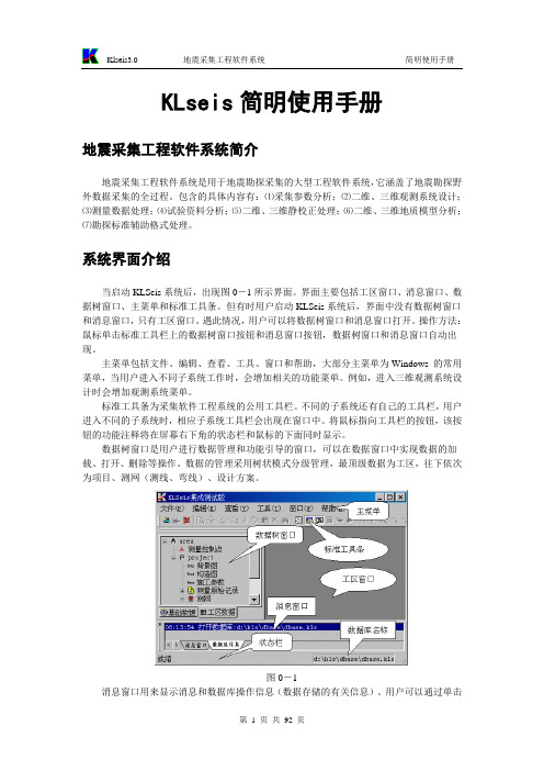
KLseis简明使用手册地震采集工程软件系统简介地震采集工程软件系统是用于地震勘探采集的大型工程软件系统,它涵盖了地震勘探野外数据采集的全过程。
包含的具体内容有:⑴采集参数分析;⑵二维、三维观测系统设计;⑶测量数据处理;⑷试验资料分析;⑸二维、三维静校正处理;⑹二维、三维地质模型分析;⑺勘探标准辅助格式处理。
系统界面介绍当启动KLSeis系统后,出现图0-1所示界面。
界面主要包括工区窗口、消息窗口、数据树窗口、主菜单和标准工具条。
但有时用户启动KLSeis系统后,界面中没有数据树窗口和消息窗口,只有工区窗口。
遇此情况,用户可以将数据树窗口和消息窗口打开。
操作方法:鼠标单击标准工具栏上的数据树窗口按钮和消息窗口按钮,数据树窗口和消息窗口自动出现。
主菜单包括文件、编辑、查看、工具、窗口和帮助,大部分主菜单为Windows 的常用菜单,当用户进入不同子系统工作时,会增加相关的功能菜单。
例如,进入三维观测系统设计时会增加观测系统菜单。
标准工具条为采集软件工程系统的公用工具栏。
不同的子系统还有自己的工具栏,用户进入不同的子系统时,相应子系统工具栏会出现在窗口中。
将鼠标指向工具栏的按钮,该按钮的功能注释将在屏幕右下角的状态栏和鼠标的下面同时显示。
数据树窗口是用户进行数据管理和功能引导的窗口,可以在数据窗口中实现数据的加载、打开、删除等操作。
数据的管理采用树状模式分级管理,最顶级数据为工区,往下依次为项目、测网(测线、弯线)、设计方案。
图0-1消息窗口用来显示消息和数据库操作信息(数据存储的有关信息)。
用户可以通过单击消息窗口下部的消息窗口标签和数据库信息标签进行切换。
消息窗口和数据树窗口可以随时打开和关闭。
工区窗口是用户进行工作的主窗口。
在刚打开时,工区窗口中并没有可以工作的窗口,当用户打开或创建一个设计方案后,该方案的工作窗口(观测系统设计窗口)才出现,此时用户可以进行观测系统设计。
主菜单当用户进入采集系统时,主菜单包括文件、编辑、查看、工具、窗口和帮助。
某重力式挡墙工程系统验算分析
某重力式挡墙工程系统验算分析 摘 要:挡墙工程在工程支挡防护工程体系中占有重要作用。本文对某挡墙工程的稳定性做了系统验算分析。同时提出应加强临河挡墙的防冲刷性能,尤其墙前地面回填部分。要加强硬化处理或布设植被,防止墙前水流冲刷脱空挡墙基底,进而导致挡墙滑移,倾覆甚至垮塌。以期能为相关工程计算进行指导和借鉴。
关键词:挡墙工程;抗滑;抗倾覆;整体稳定 中图分类号:TU46 文献标识码:A 文章编号:****
1 工程概述 挡墙工程所在项目位于江苏省扬州市三湾地区。挡墙形式采用衡重式挡墙,挡墙类型采用常规的浆砌块石挡墙,本文将根据地勘资料及规范要求,根据参考文献[1]-[7],对该挡墙断面进行稳定性分析验算,以期能为相关工程计算进行指导和借鉴。
2 土层物理力学性质及计算参数说明 2.1衡重式挡土层物理力学性质 根据岩土工程勘察报告。计算需要的部分物理力学性质指标主要有①黄~灰黄色粉质黏土,重度18.7 kN/m3,剪切强度(固快)指标Ck取10.6Kpa,φk取20.3°;③1灰色淤泥质粉质黏土,重度19.5kN/m3,剪切强度(固快)指标Ck取5.4Kpa,φk取25.3°;④灰色淤泥质黏土黄,重度19.7 kN/m3,剪切强度(固快)指标Ck取6.8Kpa,φk取26.1°。
2.2计算参数说明 本文取最不利断面挡墙最高处墙高5.63m进行计算分析。墙身尺寸: 墙身总高5.630(m),上墙高2.2(m),墙顶宽0.75(m),台宽0.6(m);面坡倾斜坡度1:0.1,上墙背坡倾斜坡度为 1:0.25,下墙背坡倾斜坡度1:-0.25,采用1个扩展墙址台阶其中墙趾台阶b1: 0.25(m),墙趾台阶h1为0.5(m),墙趾台阶与墙面坡坡度相同,墙底倾斜坡率0.1:1,下墙土压力计算方法采用力多边形法。
主要计算参数:圬工砌体容重23(kN/m3),圬工之间摩擦系数0.4,地基土摩擦系数0.4,墙身砌体容许压应力2100(kPa),墙身砌体容许剪应力110(kPa),墙身砌体容许拉应力150(kPa),墙身砌体容许弯曲拉应力280(kPa),墙后填土内摩擦角35(度),墙后填土粘聚力保守取0(kPa),墙后填土容重19(kN/m3),墙背与墙后填土摩擦角15 (度),地基土容重18 (kN/m3),修正后地基承载力特征值取170(kPa)。墙底摩擦系数取0.4,地基土内摩擦角取30(度),地基土粘聚力为10(kPa)。墙后填土浮容重9(kN/m3),地基浮力系数0.7。地震工
线弹性小变形空间板壳静力有限元计算程序
元计算有限元自动生成系统所开发源代码系列线弹性小变形空间板壳静力有限元计算程序1.简介元计算()公司所开发的并行有限元程序自动生成系统(pFEPG)可根据用户需要开发出各种有限元计算程序源代码。
该源代码系列即为pFEPG所开发出来的求解各学科典型问题的有限元计算程序。
该组程序为线弹性小变形空间板壳静力有限元计算程序。
2.starta.for,对位移场的数据进行初始化;implicit real*8 (a-h,o-z)character*12 fname,filename(20)common /aa/ ia(250000000)common /bb/ ib(125000000)c.... open disp0 file to get the numbers of nodes and degree of freedomc.... knode .... number of nodes, kdgof .... number ofd.o.f.open(1,file=' ',form='unformatted')read(1) knode,kdgofclose(1)kvar=knode*kdgofwrite(*,*) 'knode,kdgof,kvar ='write(*,'(1x,4i7)') knode,kdgof,kvarkvar1=kvar+1kcoor=3kelem=31250000knb1=kdgof*knode*1if (knb1/2*2 .lt. knb1) knb1=knb1+1kna4=kcoor*knode*2kna1=kdgof*knode*2kna2=kdgof*knode*2kna3=kdgof*knode*2kna5=knode*1if (kna5/2*2 .lt. kna5) kna5=kna5+1knb4=kelem*1if (knb4/2*2 .lt. knb4) knb4=knb4+1knb2=kvar1*1if (knb2/2*2 .lt. knb2) knb2=knb2+1knb3=kvar1*1if (knb3/2*2 .lt. knb3) knb3=knb3+1kna0=1kna1=kna1+kna0kna2=kna2+kna1kna3=kna3+kna2kna4=kna4+kna3kna5=kna5+kna4if (kna5-1.gt.250000000) thenwrite(*,*) 'exceed memory of array ia'write(*,*) 'memory of ia = 250000000'write(*,*) 'memory needed = ',kna5,' in prgram start'stop 55555endifknb0=1knb1=knb1+knb0knb2=knb2+knb1knb3=knb3+knb2knb4=knb4+knb3if (knb4-1.gt.125000000) thenwrite(*,*) 'exceed memory of array ib'write(*,*) 'memory of ib = 125000000'write(*,*) 'memory needed = ',knb4,' in prgram start'stop 55555endifcall start(knode,kdgof,kcoor,kvar,*kelem,maxt,kvar1,ia(kna0),ia(kna1),ia(kna2),*ia(kna3),ia(kna4),ib(knb0),ib(knb1),ib(knb2),*ib(knb3),*filename)endsubroutine start(knode,kdgof,kcoor,kvar,*kelem,maxt,kvar1,u0,u1,u2,*coor,inodvar,nodvar,numcol,lm,node,*filename)implicit real*8 (a-h,o-z)character*12 filename(20)DIMENSION NODV AR(KDGOF,KNODE),COOR(KCOOR,KNODE),R(3),* U0(KDGOF,KNODE),U1(KDGOF,KNODE),U2(KDGOF,KNODE),* INODV AR(KNODE),node(kelem)DIMENSION NUMCOL(KV AR1),LM(KV AR1)CHARACTER*1 MATERIALlogical filflgC .................................................................C ..... KDGOF NUMBER OF D.O.FC ..... KNODE NUMBER OF NODESC ..... INODV AR ID DATAC ..... NODV AR DENOTE THE EQUA TION NUMBER CORRESPONDING THE D.O.F C ..... U0 U1 U2 INITIAL V ALUEC ..... COOR COORDINA TESC ..... NODE ELEMENT NODAL CONNECTIONC .................................................................6 FORMAT (1X, 15I4)7 FORMAT (1X,8F9.3)C.......OPEN ID fileOPEN (1,FILE=' ',FORM='UNFORMATTED',STA TUS='OLD')READ (1) NUMNOD,NODDOF,((NODV AR(I,J),I=1,NODDOF),J=1,NUMNOD)CLOSE (1)call chms(kdgof,knode,NODV AR)c WRITE(*,*) 'NUMNOD =',NUMNOD,' NODDOF =',NODDOFc WRITE (*,*) 'ID ='c WRITE (*,6) ((NODV AR(I,J),I=1,NODDOF),J=1,NUMNOD)C..... GET THE NA TURAL NODAL ORDERDO 12 N=1,KNODEINODV AR(N)=N12 CONTINUEC..... OPEN ORDER.NOD FILE AND READ THE NODAL ORDER IF THE FILE EXISTinquire(file='ORDER.NOD',exist=filflg)if (filflg) thenOPEN (1,FILE='ORDER.NOD',FORM='UNFORMA TTED',STATUS='OLD')READ (1) (INODV AR(I),I=1,NUMNOD)CLOSE(1)WRITE(*,*) 'NODORDER ='WRITE(*,6) (INODV AR(I),I=1,NUMNOD)endifC..... GET NV BY IDNEQ=0DO 20 JNOD=1,NUMNODJ=INODV AR(JNOD)DO 18 I=1,NODDOFIF (NODV AR(I,J).NE.1) GOTO 18NEQ = NEQ + 1NODV AR(I,J) = NEQ18 CONTINUE20 CONTINUEDO 30 JNOD=1,NUMNODJ=INODV AR(JNOD)DO 28 I=1,NODDOFIF (NODV AR(I,J).GE.-1) GOTO 28N = -NODV AR(I,J)-1NODV AR(I,J) = NODV AR(I,N)28 CONTINUE30 CONTINUEC..... OPEN AND WRITE THE NV FILEOPEN(8,STATUS='unknown',FILE=' ' ,FORM='UNFORMA TTED')WRITE(8) ((NODV AR(I,J),I=1,NODDOF),J=1,NUMNOD)CLOSE(8)c WRITE(*,*) 'NUMNOD =',NUMNOD,' NODDOF =',NODDOFc WRITE(*,6) ((NODV AR(I,J),I=1,NODDOF),J=1,NUMNOD)C.... WRITE THE BOUNDAY CONDITION FILE BFD ACCORDING TO THE DISP0 FILEC....OPEN DISP0 FILEOPEN(1,FILE=' ',FORM='UNFORMATTED',STATUS='OLD')READ(1) NUMNOD,NODDOF,((U0(I,J),I=1,NODDOF),J=1,NUMNOD)CLOSE(1)C....OPEN BFD FILEOPEN(1,FILE=' ',FORM='UNFORMATTED',STATUS='unknown')WRITE(1) ((U0(I,J),I=1,NODDOF),J=1,NUMNOD)CLOSE(1)C...... GET THE INITIAL TIME FROM TIME0 FILEC.......OPEN TIME0 FileOPEN(1,FILE=' ',FORM='FORMA TTED')READ(1,*) T0,TMAX,DTTIME = T0IT = 0WRITE(*,*) ' TMAX,DT,TIME,IT =',TMAX,DT,TIME,ITCLOSE(1)C.......OPEN TIME FileOPEN(1,FILE=' ',FORM='UNFORMATTED',STATUS='unknown')WRITE(1) TMAX,DT,TIME,ITCLOSE(1)C.......OPEN COOR fileOPEN (1,FILE=' ',FORM='UNFORMATTED',STA TUS='OLD')READ (1) NUMNOD,NCOOR,((COOR(I,J),I=1,NCOOR),J=1,NUMNOD)CLOSE(1)c WRITE(*,*) 'COOR ='c WRITE(*,7) ((COOR(I,J),I=1,NCOOR),J=1,NUMNOD)C...... GET THE INITIAL V ALUE FROM THE DATA FILES BY PREPROCESSORinquire(file='disp1',exist=filflg)if (filflg) thenopen(16,file='disp1',form='unformatted',status='old')read(16) numnod,noddof,((U0(J,N),J=1,NODDOF),N=1,NUMNOD) close(16)endifinquire(file='disp2',exist=filflg)if (filflg) thenopen(16,file='disp2',form='unformatted',status='old')read(16) numnod,noddof,((U1(J,N),J=1,NODDOF),N=1,NUMNOD) close(16)endifinquire(file='disp3',exist=filflg)if (filflg) thenopen(16,file='disp3',form='unformatted',status='old')read(16) numnod,noddof,((U2(J,N),J=1,NODDOF),N=1,NUMNOD) close(16)endifc WRITE(*,*) ' U0 = 'c WRITE(*,'(6F13.3)') ((U0(J,N),J=1,NODDOF),N=1,NUMNOD) C WRITE(*,*) ' U1 = 'C WRITE(*,'(6F13.3)') ((U1(J,N),J=1,NODDOF),N=1,NUMNOD)C...... COMPUTE THE INITIAL V ALUE BY BOUND.FORzo = 0.0d0c DO 321 N=1,NUMNODc DO 100 J=1,NCOORc100 R(J) = COOR(J,N)c DO 200 J=1,NODDOFc U0(J,N) = BOUND(R,zo,J)c U1(J,N) = BOUND1(R,zo,J)c U2(J,N) = BOUND2(R,zo,J)c200 CONTINUEc321 CONTINUEC.......OPEN AND WRITE THE INITIAL VALUE FILE UNODOPEN (1,FILE=' ',FORM='UNFORMATTED',STA TUS='unknown')WRITE(1) ((U0(I,J),J=1,NUMNOD),I=1,NODDOF),* ((U1(I,J),J=1,NUMNOD),I=1,NODDOF),* ((U2(I,J),J=1,NUMNOD),I=1,NODDOF),* ((U0(I,J),J=1,NUMNOD),I=1,NODDOF)CLOSE (1)c.... open IO fileopen(21,file=' ',form='formatted',status='old')read(21, '(1a)') materialread(21,*) numtypclose(21)DO I=1,NEQNUMCOL(i)=1ENDDOC.......OPEN ELEM0 fileOPEN (3,FILE=' ',FORM='UNFORMATTED',STA TUS='OLD')NUMEL=0KELEM=0KEMATE=0DO 2000 ITYP=1,NUMTYPC.......INPUT ENODEREAD (3) NUM,NNODE,* ((NODE((I-1)*NNODE+J),J=1,NNODE),I=1,NUM)cc WRITE(*,*) 'NUM =',NUM,' NNODE =',NNODEcc WRITE(*,*) 'NODE ='cc WRITE(*,6) ((NODE((I-1)*NNODE+J),J=1,NNODE),I=1,NUM) IF (KELEM.LT.NUM*NNODE) KELEM = NUM*NNODENNE = NNODEIF (MATERIAL.EQ.'Y' .OR. MATERIAL.EQ.'y') THENREAD (3) MMATE,NMATEIF (KEMATE.LT.MMATE*NMATE) KEMATE = MMATE*NMATENNE = NNE-1ENDIFWRITE(*,*) 'MMATE =',MMATE,' NMATE =',NMATEcc WRITE(*,*) 'NUM =',NUM,' NNODE =',NNODEcc WRITE(*,*) 'NODE ='cc WRITE(*,6) ((NODE((I-1)*NNODE+J),J=1,NNODE),I=1,NUM) DO 1000 NE=1,NUML=0DO 700 INOD=1,NNENODI=NODE((NE-1)*NNODE+INOD)DO 600 IDGF=1,KDGOFINV=NODV AR(IDGF,NODI)IF (INV.LE.0) GOTO 600L=L+1LM(L)=INV600 CONTINUE700 CONTINUENUMEL=NUMEL+1C WRITE (*,*) 'L,LM =',LC WRITE (*,'(1X,15I5)') (LM(I),I=1,L)if (l.gt.0) call ACLH(NEQ,NUMCOL,l,lm)1000 continue2000 CONTINUEc CLOSE(1)CLOSE(3)call BCLH(NEQ,NUMCOL)MAXA=NUMCOL(NEQ)C.......OPEN SYS FileOPEN (2,FILE=' ',FORM='UNFORMATTED',STA TUS='unknown') WRITE(2) NUMEL,NEQ,NUMTYP,MAXA,KELEM,KEMATECLOSE (2)OPEN(2,FILE=' ',FORM='UNFORMATTED',STATUS='unknown')write(2) (NUMCOL(I),I=1,NEQ)CLOSE(2)c write(*,*) 'NEQ,NUMCOL=',NEQc write(*,6) (NUMCOL(i),i=1,NEQ)ENDsubroutine chms(kdgof,knode,id)dimension id(kdgof,knode),ms(1000),is(1000)do 1000 k=1,kdgofm = 0do 800 n=1,knodeif (id(k,n).le.-1) id(k,n)=-1if (id(k,n).le.1) goto 800j=id(k,n)j0=0if (m.gt.0) thendo i=1,mif (j.eq.ms(i)) j0=is(i)enddoendifif (j0.eq.0) thenm=m+1ms(m)=jis(m)=nid(k,n)=1elseid(k,n)=-j0-1endif800 continue1000 continuereturnendSUBROUTINE ACLH(NEQ,NUMCOL,ND,LM)implicit real*8 (a-h,o-z)DIMENSION LM(ND),NUMCOL(NEQ)LS=LM(1)+1DO 100 I=1,ND110 IF(LM(I)-LS) 120,100,100120 LS=LM(I)100 CONTINUEDO 200 I=1,NDII=LM(I)ME=II-LSIF(ME.GT.NUMCOL(II)) NUMCOL(II)=ME 200 CONTINUERETURNENDSUBROUTINE BCLH(NEQ,NUMCOL)implicit real*8 (a-h,o-z)DIMENSION NUMCOL(NEQ)C NUMCOL(1) = 1DO 490 I=2,NEQ490 NUMCOL(I) = NUMCOL(I) + NUMCOL(I-1) + 1 RETURNEND3.eshell3da.for,Galerkin法求解位移场的主程序implicit real*8 (a-h,o-z)character*12 fname,filename(20)common /aa/ ia(250000000)common /bb/ ib(125000000)common /cc/ ic(62500000)open(1,file=' ',form='unformatted',status='old')read(1) knode,kdgofclose(1)MAXT=250000000/2/2C.......OPEN SYS FileOPEN (2,FILE=' ',FORM='UNFORMATTED',STA TUS='OLD')read(2) NUMEL,NEQ,NUMTYP,MAXA,KELEM,KEMATECLOSE (2)IF (MAXA.GT.MAXT) THENWRITE(*,*) 'MATRIX A EXCEED CORE MEMERY .... ',MAXA WRITE(*,*) 'REQUIRED CORE MEMERY ........... ',MAXTSTOP 0000ENDIFKV AR=KNODE*KDGOFKCOOR=3C KELEM=31250000WRITE(*,*) 'KNODE,KDGOF,KV AR,KCOOR,KELEM ='WRITE(*,'(1X,6I7)') KNODE,KDGOF,KV AR,KCOOR,KELEMkna1=kdgof*knode*1if (kna1/2*2 .lt. kna1) kna1=kna1+1knc1=kdgof*knode*2knc2=kcoor*knode*2knc7=kdgof*knode*2knc3=neq*2knb1=maxa*2knb2=maxa*2kna2=neq*1if (kna2/2*2 .lt. kna2) kna2=kna2+1knc6=kemate*2kna3=kelem*1if (kna3/2*2 .lt. kna3) kna3=kna3+1knc8=100000*2knc5=neq*2knc4=kdgof*knode*2kna0=1kna1=kna1+kna0kna2=kna2+kna1kna3=kna3+kna2if (kna3-1.gt.125000000) thenwrite(*,*) 'exceed memory of array ib'write(*,*) 'memory of ib = 125000000'write(*,*) 'memory needed = ',kna3,' in prgram eshell3da'stop 55555endifknb0=1knb1=knb1+knb0knb2=knb2+knb1if (knb2-1.gt.250000000) thenwrite(*,*) 'exceed memory of array ia'write(*,*) 'memory of ia = 250000000'write(*,*) 'memory needed = ',knb2,' in prgram eshell3da'stop 55555endifknc0=1knc1=knc1+knc0knc2=knc2+knc1knc3=knc3+knc2knc4=knc4+knc3knc5=knc5+knc4knc6=knc6+knc5knc7=knc7+knc6knc8=knc8+knc7if (knc8-1.gt.62500000) thenwrite(*,*) 'exceed memory of array ic'write(*,*) 'memory of ic = 62500000'write(*,*) 'memory needed = ',knc8,' in prgram eshell3da'stop 55555endifcall eshell3da(knode,kdgof,kvar,kcoor,*numtyp,numel,neq,kelem,kemate,maxa,*maxt,neq1,ib(kna0),ib(kna1),ib(kna2),*ia(knb0),ia(knb1),ic(knc0),ic(knc1),ic(knc2),*ic(knc3),ic(knc4),ic(knc5),ic(knc6),ic(knc7),*filename)endsubroutine eshell3da(knode,kdgof,kvar,kcoor,*numtyp,numel,neq,kelem,kemate,maxa,*maxt,neq1,nodvar,jdiag,node,a,*b,u,coor,f,ubf,u1,*emate,eu,sml,*filename)implicit real*8 (a-h,o-z)character*12 filename(20)DIMENSIONNODV AR(KDGOF,KNODE),U(KDGOF,KNODE),COOR(KCOOR,KNODE), *eu(kdgof,knode),& F(NEQ),A(MAXA),B(MAXA),JDIAG(NEQ),EMATE(KEMATE),& NODE(KELEM),SML(100000),u1(neq),UBF(KDGOF,KNODE)6 FORMA T (1X,15I5)7 FORMA T (1X,5e15.5)1001 FORMA T(1X,9I7)C.......OPEN TIME FileOPEN(1,FILE=' ',FORM='UNFORMATTED',STATUS='OLD')READ(1) TMAX,DT,TIME,ITWRITE(*,*) ' TMAX,DT,TIME,IT =',TMAX,DT,TIME,ITCLOSE(1)C.......OPEN NODV AR fileOPEN (1,FILE=' ',FORM='UNFORMATTED',STA TUS='OLD')READ (1) ((NODV AR(I,J),I=1,KDGOF),J=1,KNODE)CLOSE (1)cc WRITE(*,*) 'KDGOF =',KDGOF,' KNODE =',KNODEcc WRITE (*,*) 'NODV AR ='cc WRITE (*,6) ((NODV AR(I,J),I=1,KDGOF),J=1,KNODE)C.......OPEN COOR fileOPEN (1,FILE=' ',FORM='UNFORMATTED',STA TUS='OLD')READ (1) NUMNOD,NCOOR,((COOR(I,J),I=1,NCOOR),J=1,NUMNOD) CLOSE(1)cc WRITE(*,*) 'NUMNOD,NCOOR=',NUMNOD,NCOORC.......OPEN BFD fileOPEN (1,FILE=' ',FORM='UNFORMATTED',STA TUS='OLD')READ (1) ((UBF(J,I),J=1,KDGOF),I=1,KNODE)CLOSE (1)cc WRITE (*,*) 'BF ='cc WRITE(*,7) ((UBF(J,I),J=1,KDGOF),I=1,KNODE)numtyp = 1C.......OPEN DIAG fileOPEN (2,FILE=' ',FORM='UNFORMATTED',STA TUS='OLD')READ(2) (JDIAG(I),I=1,NEQ)CLOSE(2)C.......OPEN ELEM0 fileOPEN (3,FILE=' ',FORM='UNFORMATTED',STA TUS='OLD')itime=01 continueitime=itime+1if (itime.gt.1) thenwrite(*,*) 'Nonlinear Iteration Times ========',itimerewind(3)endifDO 111 I=1,KNODEDO 111 J=1,KDGOFU(J,I) = UBF(J,I)111 CONTINUEcc WRITE (*,*) 'BF ='cc WRITE(*,7) ((U(J,I),J=1,KDGOF),I=1,KNODE)DO 112 I=1,MAXAA(I) = 0.0B(I) = 0.0112 CONTINUEDO 2300 I=1,NEQ2300 CONTINUENUMEL=0C.......OPEN EMA TE+ENODE+ELOAD fileC OPEN (3,FILE=' ',FORM='UNFORMA TTED',STATUS='OLD')DO 2000 ITYP=1,NUMTYPC.......INPUT ENODEREAD (3) NUM,NNODE,* ((NODE((I-1)*NNODE+J),J=1,NNODE),I=1,NUM)cc WRITE(*,*) 'NUM =',NUM,' NNODE =',NNODEcc WRITE(*,*) 'NODE ='cc WRITE(*,6) ((NODE((I-1)*NNODE+J),J=1,NNODE),I=1,NUM) NNE = NNODEnne = nne-1K=0DO 115 J=1,NNEJNOD = NODE(J)DO 115 L=1,KDGOFIF (NODV AR(L,JNOD).NE.0) K=K+1115 CONTINUEWRITE(*,*) 'K =',Kkk=k*kk0=1k1=k0+k*kk2=k1+kk3=k2+kk4=k3+k*kk5=k4+k*kCALL ETSUB(KNODE,KDGOF,IT,KCOOR,KELEM,K,KK,NNODE,NNE, * ITYP,NCOOR,NUM,TIME,DT,neq,maxa,NODV AR,COOR,NODE,EMATE,& A,B,JDIAG,&sml(k0),sml(k1),sml(k2),sml(k3),sml(k4),&eu,*U)2000 CONTINUEDO 2050 IJ=1,NEQif (itime.le.1) u1(IJ) = 0.0F(IJ)=0.0D02050 CONTINUEDO 2200 I=1,KNODEDO 2100 J=1,KDGOFIJ=NODV AR(J,I)IF (IJ.LE.0) GOTO 2100F(IJ)=F(IJ)+U(J,I)U1(IJ)=F(IJ)2100 CONTINUE2200 CONTINUECC IF (IT.GT.0) THENcc WRITE (*,*) 'U ='cc WRITE (*,7) ((U(J,I),J=1,KDGOF),I=1,KNODE)cc WRITE (*,*) 'NEQ =',NEQ,' F ='cc WRITE(*,7) (F(I),I=1,NEQ)if (itime.le.1) thenC.......OPEN LMATRIX FILEOPEN (2,FILE=' ',FORM='UNFORMATTED',STA TUS='unknown')CLOSE (2)endifWRITE(*,*) 'NIN_SOLVER MEMORY REQUIRED .... ',MAXAIF (MAXA.GT.MAXT) THENWRITE(*,*) 'WARNING MA TRIX A EXCEED CORE MEMORY .... ',MAXT c STOP 0000ENDIFCALL REDU(A,B,U1,JDIAG,NEQ,MAXA,1)C WRITE(*,*) ' U1 = 'C WRITE(*,7) (A(I),I,MAXA)C WRITE(*,7) (F(I),I=1,NEQ)NOUT = 20OPEN(NOUT,FILE=' ',FORM='FORMATTED',STATUS='unknown')DO 3200 INOD=1,KNODEDO 3100 IDFG=1,KDGOFN=NODV AR(IDFG,INOD)C WRITE (*,*) 'N =',Nif(n.le.0) theneu(IDFG,INOD)=u(IDFG,INOD)elseeu(IDFG,INOD)=u1(N)endif3100 CONTINUE3200 CONTINUEDO 3400 N=1,KNODEWRITE (NOUT,3600) N,(eu(I,N),I=1,KDGOF)3400 CONTINUE3600 FORMA T (1X,I5,1X,6E11.4,9(/6X,6E11.4))CLOSE (NOUT)open(10,file='unod',form='unformatted',status='unknown')write(10) ((eu(j,i),i=1,knode),j=1,kdgof)close(10)close (3)RETURNENDSUBROUTINE ETSUB(KNODE,KDGOF,IT,KCOOR,KELEM,K,KK,NNODE,NNE, *ITYP,NCOOR,NUM,TIME,DT,neq,maxa,NODV AR,COOR,NODE,EMATE,&A,B,JDIAG,*es,em,ef,Estifn,Estifv,eu,*U)implicit real*8 (a-h,o-z)DIMENSIONNODV AR(KDGOF,KNODE),COOR(KCOOR,KNODE),NODE(KELEM),*U(KDGOF,KNODE),EMA TE(300),&A(MAXa),B(MAXa),JDIAG(neq),*es(k,k),em(k),ef(k),eu(kdgof,knode),*Estifn(k,k),Estifv(kk),*R(500),PRMT(500),COEF(500),LM(500)17 FORMA T (1X,15I5)18 FORMA T (1X,8e9.2)READ (3) MMA TE,NMATE,((EMATE((I-1)*NMATE+J),J=1,NMATE),* I=1,MMATE)WRITE(*,*) 'MMATE =',MMATE,' NMATE =',NMATEWRITE (*,*) 'EMATE ='WRITE (*,18) ((EMATE((I-1)*NMATE+J),J=1,NMATE),* I=1,MMATE)DO 1000 NE=1,NUMNR=0DO 130 J=1,NNEJNOD = NODE((NE-1)*NNODE+J)IF (JNOD.LT.0) JNOD = -JNODPRMT(NMA TE+7+J) = JNODDO 120 I=1,NCOORNR=NR+1120 R(NR) = COOR(I,JNOD)130 CONTINUEIMA TE = NODE(NNODE*NE)DO 140 J=1,NMATE140 PRMT(J) = EMA TE((IMATE-1)*NMATE+J) PRMT(NMATE+1)=TIMEPRMT(NMATE+2)=DTPRMT(NMA TE+3)=IMATEprmt(NMA TE+4)=NEprmt(NMA TE+5)=NUMprmt(NMA TE+6)=ITprmt(NMA TE+7)=NMATEprmt(NMA TE+8)=ITIMEprmt(NMA TE+9)=ITYPgoto 11 call csugt3m(r,coef,prmt,es,em,ec,ef,ne)goto 22 continueC WRITE(*,*) 'ES EM EF ='C DO 555 I=1,KC555 WRITE(*,18) (ES(I,J),J=1,K)C WRITE(*,18) (EM(I),I=1,K)C WRITE(*,18) (EF(I),I=1,K)CC IF (IT.GT.0) THENdo 201 i=1,kdo 201 j=1,kEstifn(i,j)=0.0201 continuedo 202 i=1,kEstifn(i,i)=Estifn(i,i)do 202 j=1,kEstifn(i,j)=Estifn(i,j)+es(i,j)202 continueL=0M=0I=0DO 700 INOD=1,NNENODI=NODE((NE-1)*NNODE+INOD)DO 600 IDGF=1,KDGOFINV=NODV AR(IDGF,NODI)IF (INV.EQ.0) GOTO 600I=I+1IF (INV.LT.0) GOTO 305L=L+1LM(L)=INVU(IDGF,NODI)=U(IDGF,NODI)*+ef(i)305 J=0DO 500 JNOD=1,NNENODJ=NODE((NE-1)*NNODE+JNOD)DO 400 JDGF=1,KDGOFJNV=NODV AR(JDGF,NODJ)IF (JNV.EQ.0) GOTO 400J=J+1IF (JNV.LT.0) GOTO 400IF (INV.LT.0) GOTO 310M=M+1Estifv(m)=Estifn(i,j)310 CONTINUEIF (INV.LT.0)* U(JDGF,NODJ)=U(JDGF,NODJ)-ESTIFN(I,J)*U(IDGF,NODI) 400 CONTINUE500 CONTINUE600 CONTINUE700 CONTINUEC WRITE (*,*) 'U ='C WRITE (*,18) ((U(J,I),J=1,KDGOF),I=1,KNODE)LRD=MNER=NUMEL+NEC WRITE(*,*) '**************************'C WRITE(*,*) (ESTIFV(I),I=1,LRD)C WRITE (*,*) 'Einform ............'C WRITE (*,'(1X,15I5)') L,LRD,(LM(I),I=1,L)DO 800 I=1,LJ=LM(I)800 CONTINUEcall ADDA(A,B,JDIAG,L,LM,ESTIFV,NEQ,MAXA)1000 CONTINUERETURNENDSUBROUTINE ADDA(A,B,JDIAG,ND,LM,ESTIF,NEQ,MAXA)implicit real*8 (a-h,o-z)DIMENSION A(MAXA),B(MAXA),JDIAG(NEQ),LM(ND),ESTIF(ND,ND) C WRITE (*,*) ND, (LM(I),I=1,ND)C WRITE (*,*) ((ESTIF(I,J),J=1,ND),I=1,ND)DO 300 I=1,NDII = LM(I)DO 280 J=1,IJJ = LM(J)IF (II.LT.JJ) GOTO 240K = JDIAG(II) - II + JJA(K) = A(K) + ESTIF(I,J)B(K) = B(K) + ESTIF(J,I)GOTO 280240 K = JDIAG(JJ) - JJ + IIB(K) = B(K) + ESTIF(I,J)A(K) = A(K) + ESTIF(J,I)280 CONTINUE300 CONTINUERETURNENDSUBROUTINE REDU(A,B,U,JDIAG,NEQ,MAXA,KKK)implicit real*8 (a-h,o-z)DIMENSION A(MAXA),B(MAXA),JDIAG(NEQ),U(NEQ)DOUBLE PRECISION CPUTE L U & u, L*U(T) = A, A*u = fDO 500 I=2,NEQI1 = I-1NI = JDIAG(I)LI = I-NI+JDIAG(I-1)+1IF (KKK.GT.1) GOTO 333DO 200 J=LI,INJ = JDIAG(J)LJ = J-NJ+1IF (J.GT.1) LJ = LJ+JDIAG(J-1)LIJ = MAX0(LI,LJ)J1 = J-1IF (J.EQ.I) GOTO 130C = 0.0D0DO 100 L=LIJ,J1100 C = C + A(NI-I+L)*B(NJ-J+L)A(NI-I+J) = (A(NI-I+J) - C)/B(NJ)130 C = 0.0D0DO 150 L=LIJ,J1150 C = C + B(NI-I+L)*A(NJ-J+L)200 B(NI-I+J) = B(NI-I+J) - C333 C = 0.0D0DO 400 L=LI,I1400 C = C + A(NI-I+L)*U(L)U(I) = U(I)-C500 CONTINUEJ = MAXA + 1N = NEQ + 1700 N = N - 1J = J - 1U(N) = U(N)/B(J)IF (N.EQ.1) GOTO 999M = J-JDIAG(N-1)-1DO 800 I=1,MJ = J - 1800 U(N-I) = U(N-I) - B(J)*U(N)GOTO 700999 RETURNEND3.1.csult3m.for,计算板壳单元刚度矩阵和荷载向量的子程序subroutine csult3m(coorr,coefr,& prmt,estif,emass,edamp,eload,num)c .... coorr ---- nodal coordinate valuec .... coefr ---- nodal coef valueimplicit real*8 (a-h,o-z)common /csult3mcom1/ det,d1,d2,d3,b1,b2,b3dimension estif(18,18),elump(18),emass(18),& eload(18)dimension prmt(*),& eekx(18),eeky(18),eekxy(18),egmx(18),& egmy(18),eex(18),eey(18),eexy(18),& coorr(2,3),coor(2)common /rcsult3m/ru(3,18),rv(3,18),rw(9,18),& rs(9,18),ro(9,18),rc(3,18),& cu(3,3),cv(3,3),cw(9,3),cs(9,3),& co(9,3),cc(3,3)c .... store shape functions and their partial derivativesc .... for all integral pointscommon /vcsult3m/rctr(2,2),crtr(2,2)common /dcsult3m/ refc(2,6),gaus(6),& nnode,ngaus,ndisp,nrefc,ncoor,nvar,& nvard(6),kdord(6),kvord(18,6)c .... nnode ---- the number of nodesc .... nrefc ---- the number of numerical integral pointsc .... ndisp ---- the number of unknown functionsc .... nrefc ---- the number of reference coordinatesc .... nvar ---- the number of unknown varibles varc .... refc ---- reference coordinates at integral pointsc .... gaus ---- weight number at integral pointsc .... nvard ---- the number of var for each unknownc .... kdord ---- the highest differential order for each unknown c .... kvord ---- var number at integral points for each unknownpe=prmt(1)pv=prmt(2)thick=prmt(3)fu=prmt(4)fv=prmt(5)fw=prmt(6)rou=prmt(7)alpha=prmt(8)time=prmt(9)dt=prmt(10)imate=prmt(11)+0.5ielem=prmt(12)+0.5nelem=prmt(13)+0.5it=prmt(14)+0.5nmate=prmt(15)+0.5itime=prmt(16)+0.5ityp=prmt(17)+0.5fact = pe*thick**3/12./(1.-pv*pv)fact2 = pe/(1.+pv)/(1.-pv)*thickb1=coorr(2,2)-coorr(2,3)b2=coorr(2,3)-coorr(2,1)b3=coorr(2,1)-coorr(2,2)d1=-coorr(1,2)+coorr(1,3)d2=-coorr(1,3)+coorr(1,1)d3=-coorr(1,1)+coorr(1,2)if (num.eq.1) call csult3mic .... initialize the basic datado 10 i=1,nvareload(i)=0.0do 10 j=1,nvarestif(i,j)=0.010 continuedo 999 igaus=1,ngauscall csult3mt(nnode,nrefc,ncoor,refc(1,igaus),coor,coorr, & rctr,crtr,det)c .... coordinate transfer from reference to original systemc .... rctr ---- Jacobi's matrixc .... crtr ---- inverse matrix of Jacobi's matrixx=coor(1)y=coor(2)r=refc(1,igaus)z=refc(2,igaus)iu=(igaus-1)*3+1iv=(igaus-1)*3+1iw=(igaus-1)*3+1is=(igaus-1)*3+1io=(igaus-1)*3+1ic=(igaus-1)*3+1c .... the following is the shape function caculationcall csult3m1(refc(1,igaus),ru(1,iu),rctr,crtr)call csult3m2(refc(1,igaus),rv(1,iv),rctr,crtr)call csult3m3(refc(1,igaus),rw(1,iw),rctr,crtr)call csult3m4(refc(1,igaus),rs(1,is),rctr,crtr)call csult3m5(refc(1,igaus),ro(1,io),rctr,crtr)call csult3m6(refc(1,igaus),rc(1,ic),rctr,crtr)c .... the following is the shape function transformationc .... from reference coordinates to original coordinatescall shapn(nrefc,ncoor,3,ru(1,iu),cu,crtr,1,3,3)call shapn(nrefc,ncoor,3,rv(1,iv),cv,crtr,1,3,3)call shapn(nrefc,ncoor,9,rw(1,iw),cw,crtr,1,3,3)call shapn(nrefc,ncoor,9,rs(1,is),cs,crtr,1,3,3)call shapn(nrefc,ncoor,9,ro(1,io),co,crtr,1,3,3)call shapn(nrefc,ncoor,3,rc(1,ic),cc,crtr,1,3,3)weigh=det*gaus(igaus)do 100 i=1,18eekx(i) = 0.0eeky(i) = 0.0eekxy(i) = 0.0egmx(i) = 0.0egmy(i) = 0.0eex(i) = 0.0eey(i) = 0.0eexy(i) = 0.0100 continueif (det .lt. thick*thick) thenfact1 =5.*pe*thick/24./(1.+pv)elsefact1 =5.*pe*thick**3/det/24./(1.+pv)endifdo 101 i=1,9iv=kvord(i,5)stif=+co(i,2)eekx(iv)=eekx(iv)+stif101 continuedo 102 i=1,9iv=kvord(i,4)stif=-cs(i,3)eeky(iv)=eeky(iv)+stif102 continuedo 103 i=1,9iv=kvord(i,4)stif=-cs(i,2)eekxy(iv)=eekxy(iv)+stif103 continuedo 104 i=1,9iv=kvord(i,5)stif=+co(i,3)eekxy(iv)=eekxy(iv)+stif104 continuedo 105 i=1,9iv=kvord(i,3)stif=+cw(i,2)egmx(iv)=egmx(iv)+stif105 continuedo 106 i=1,9iv=kvord(i,5)stif=+co(i,1)egmx(iv)=egmx(iv)+stif106 continuedo 107 i=1,9iv=kvord(i,3)stif=+cw(i,3)egmy(iv)=egmy(iv)+stif107 continuedo 108 i=1,9iv=kvord(i,4)stif=-cs(i,1)egmy(iv)=egmy(iv)+stif108 continuedo 109 i=1,3iv=kvord(i,1)stif=+cu(i,2)eex(iv)=eex(iv)+stif109 continuedo 110 i=1,3iv=kvord(i,2)stif=+cv(i,3)eey(iv)=eey(iv)+stif110 continuedo 111 i=1,3iv=kvord(i,1)stif=+cu(i,3)eexy(iv)=eexy(iv)+stif111 continuedo 112 i=1,3iv=kvord(i,2)stif=+cv(i,2)eexy(iv)=eexy(iv)+stif112 continuec .... the following is the stiffness computationdo 202 i=1,3iv=kvord(i,6)do 201 j=1,3jv=kvord(j,6)stif=+cc(i,1)*cc(j,1)*pe*1.0e-6estif(iv,jv)=estif(iv,jv)+stif*weigh 201 continue202 continuedo 204 iv=1,18do 203 jv=1,18stif=+eekx(iv)*eekx(jv)*fact*1.& +eekx(iv)*eeky(jv)*fact*pv& +eeky(iv)*eekx(jv)*fact*pv& +eeky(iv)*eeky(jv)*fact*1.& +eekxy(iv)*eekxy(jv)*fact*(1.-pv)/2.& +egmx(iv)*egmx(jv)*fact1*2.& +egmy(iv)*egmy(jv)*fact1*2.& +eex(iv)*eex(jv)*fact2*(1.)& +eex(iv)*eey(jv)*fact2*(pv)& +eey(iv)*eex(jv)*fact2*(pv)& +eey(iv)*eey(jv)*fact2*(1.)& +eexy(iv)*eexy(jv)*fact2*((1.-pv)/2)estif(iv,jv)=estif(iv,jv)+stif*weigh203 continue204 continuec .... the following is the load vector computationdo 501 i=1,3iv=kvord(i,1)stif=+cu(i,1)*fueload(iv)=eload(iv)+stif*weigh501 continuedo 502 i=1,3iv=kvord(i,2)stif=+cv(i,1)*fveload(iv)=eload(iv)+stif*weigh502 continuedo 503 i=1,9iv=kvord(i,3)stif=+cw(i,1)*fweload(iv)=eload(iv)+stif*weigh503 continue999 continue998 continuereturnendsubroutine csult3miimplicit real*8 (a-h,o-z)common /dcsult3m/ refc(2,6),gaus(6),& nnode,ngaus,ndisp,nrefc,ncoor,nvar,& nvard(6),kdord(6),kvord(18,6)c .... initial datac .... refc ---- reference coordinates at integral points c .... gaus ---- weight number at integral pointsc .... nvard ---- the number of var for each unknownc .... kdord ---- the highest differential order for each unknown c .... kvord ---- var number at integral points for each unknownngaus= 6ndisp= 6nrefc= 2ncoor= 2nvar = 18nnode= 3kdord(1)=1nvard(1)=3kvord(1,1)=1kvord(2,1)=7kvord(3,1)=13kdord(2)=1nvard(2)=3kvord(1,2)=2kvord(2,2)=8kvord(3,2)=14kdord(3)=1nvard(3)=9kvord(1,3)=3kvord(2,3)=9kvord(3,3)=15kvord(4,3)=4kvord(5,3)=10kvord(6,3)=16kvord(7,3)=5kvord(8,3)=11kvord(9,3)=17kdord(4)=1nvard(4)=9kvord(1,4)=3kvord(2,4)=9kvord(3,4)=15kvord(4,4)=4kvord(5,4)=10kvord(6,4)=16kvord(7,4)=5kvord(8,4)=11kvord(9,4)=17kdord(5)=1nvard(5)=9kvord(1,5)=3。
BTN7971资料
4
General Product Characteristics
4.1
Absolute Maximum Ratings
Absolute Maximum Ratings 1)
Tj = -40 °C to +150 °C; all voltages with respect to ground, positive current flowing into pin
IN Gate Driver
LS
INH
SR
Slewrate Adjustment
Overcurr. Detection
LS
3
3.1
Pin Configuration
Pin Assignment
8
VS OUT GND
Pin
Symbol
1
GND
2
INΒιβλιοθήκη 3INH4,8
OUT
5
SR
6
IS
7
VS
1234 5 67
I/O Function
-
Ground
I
Input
Defines whether high- or lowside switch is activated
I
Inhibit
When set to low device goes in sleep mode
O
Power output of the bridge
The BTN7971B provides a cost optimized solution for protected high current PWM motor drives with very low board space consumption.
Agilent8902A测量接收机技术说明书
The Agilent Technologies 8902A measuring receiver delivers the accuracy and resolution of a high per-formance power meter at frequencies from 150 kHz to 1.3 GHz (50 MHz to 26.5 GHz with the Agilent 11793A microwave converter) and levels from+30 dBm to –127 dBm. It accurately measures AM, FM, and f M, including residuals and incidentals, with a single keystroke. The 8902A measuring receiver, with the 11793A, counts RF signals to 26.5 GHz with 10 Hz resolution and excellent long-term frequency stability. The 8902A measuring receiver with Option 050 offers increased power measurement accuracy. This option specifies Tuned RF Level on the 8902A measuring receiver to an accuracy of ±(0.015 dB + 0.005 dB/10 dB step). Agilent 8902AMeasuring Receiver Technical SpecificationsAgilent 11722A Sensor ModuleAgilent 11792A Sensor ModuleAgilent 11793A Microwave ConverterAgilent 11812A Verification Kit2AGILENT 8902A MEASURING RECEIVER*TECHNICAL SPECIFICATIONSSpecifications describe the test set’s warranted performance and are valid over the entire operation and environmental ranges unless otherwise noted. All specifications are valid after a 30-minute warm-up period of continuous opera-tion, and within the frequency ranges defined below.Supplemental characteristics are intended to provide additional information useful in applying the instru-ment by giving typical, but non-warranted performance parameters. These characteristics are shown in Italics and labeled as “nominal,” “typical,” or “supplemental.”*Shaded text signifies measurements made with the 8902A measuring receiver using the 11793A microwave converter and 11792A sensor module. With this config-uration, all standard 8902A specifications apply except where changes are shown as shaded text.Frequency ModulationRATES 1:20 Hz to 10 kHz, 150 kHz ≤f c <10 MHz.20 Hz to 200 kHz, 10 MHz ≤f c ≤1300 MHz.20 Hz to 200 kHz, 10 MHz ≤f c ≤26.5 GHz.DEVIATIONS 1:40 kHz peak maximum, 150 kHz ≤f c <10 MHz.400 kHz peak maximum, 10 MHz ≤f c ≤1300 MHz.400 kHz peak maximum, 10 MHz ≤f c ≤26.5 GHz.ACCURACY 1, 2, 3:FM Accuracy Frequency Range Rates Deviations ±2% of reading 250 kHz – 10 MHz 20 Hz – 10 kHz ≤40 kHz peak ±1 digit ±1% of reading 10 MHz – 1300 MHz 50 Hz – 100 kHz ≤400 kHz peak ±1 digit ±5% of reading 10 MHz – 1300 MHz 20 Hz – 200 kHz ≤400 kHz peak ±1 digitFor rms detector add ±3% of reading.DEMODULATED OUTPUT DISTORTION 1, 4:THD Frequency Range Rates Deviations <0.1%400 kHz – 10 MHz 20 Hz – 10 kHz <10 kHz <0.1%10 MHz – 1300 MHz 20 Hz – 100 kHz <100 kHz AM REJECTION (50 Hz to 3 kHz BW)3:AM RejectionFrequency Range Rates AM Depths <20 Hz peak 150 kHz – 1300 MHz 400 Hz or 1 kHz ≤50%deviation RESIDUAL FM (50 Hz to 3 kHz BW):<8 Hz rms at 1300 MHz, decreasing linearly with frequency to <1 Hz rms for 100 MHz and below.<17 Hz rms'1300 MHz <f c ≤6.2 GHz.<33 Hz rms'6.2 GHz <f c ≤12.4 GHz.<49 Hz rms'12.4 GHz <f c ≤18.6 GHz.<65 Hz rms'18.6 GHz <f c ≤26.5 GHz.Supplemental Characteristics:MAXIMUM FM DEVIATION, RESOLUTION, AND MAXIMUM DEMODULATED OUTPUT SENSITIVITYACROSS AN OPEN CIRCUIT (600 Ωoutput impedance)5:Maximum Maximum Demodulated Deviations Resolution Output Sensitivity(D F)100 Hz 0.01 mV/Hz D F peak ≥40 kHz 10 Hz 0.1 mV/Hz 4.0 kHz ≤D F peak <40 kHz 1 Hz 1.0 mV/Hz D F peak < 4 kHz 0.1 Hz1.0 mV/ HzD F rms < 0.3 kHz(rms detector only)Resolution is increased one digit with 750 µs de-empha-sis and pre-display on.The demodulated output signal present at theModulation Out/Audio In connector is increased in amplitude by a factor of 10 with 750 µs de-emphasis.DEMODULATED OUTPUT DISTORTION 1, 4:THD Frequency Range Rates Deviations <0.3%150 kHz – 400 kHz 20 Hz – 10 kHz <10 kHz DETECTORS:+peak, – peak, ±peak/2, peak hold, average (rms sinewave calibrated), rms.STEREO SEPARATION (50 Hz to 15 kHz): >47 dB.1.But not to exceed: 20 kHz rates and 40 kHz peak deviations with 750 µs de-emphasis filter.2.Not to exceed for stated accuracy: 50 Hz to 40 kHz rates with rms detector.3.Peak residuals must be accounted for in peak readings.4.With 750 µs de-emphasis and pre-display "off," distortion is not specified for modulation outputs >4V peak. This condition can occur near maximum deviation for a measurement range, at rates <2 kHz.5.For optimum flatness, cables should be terminated with their characteristic impedance.3Amplitude ModulationRATES:20 Hz to 10 kHz, 150 kHz ≤f c <10 MHz.20 Hz to 100 kHz, 10 MHz ≤f c ≤1300 MHz.DEPTH:to 99%.ACCURACY 2, 3, 6:AM Accuracy Frequency Range Rates Depths ±2% of reading 150 kHz – 10 MHz 50 Hz – 10 kHz 5% – 99%±1 digit ±3% of reading 150 kHz – 10 MHz 20 Hz – 10 kHz to 99%±1 digit ±1% of reading 10 MHz – 1300 MHz 50 Hz – 50 kHz 5% – 99%±1 digit ±3% of reading 10 MHz – 1300 MHz20 Hz – 100 kHz to 99%±1 digitFLATNESS 5, 7:Flatness Frequency Range RatesDepths±0.3% of reading10 MHz – 1300 MHz 90 Hz – 10 kHz 20% – 80%±1 digit DEMODULATED OUTPUT DISTORTION:<0.3% THD for ≤50% depth. <0.6% THD for ≤95% depth.For f c >1300 MHz add 0.4% THD.FM REJECTION (50 Hz to 3 kHz BW)3:FM Rejection Frequency Range Rates Deviations <0.2% AM250 kHz – 10 MHz 400 Hz or 1 kHz <5 kHz peak <0.2% AM 10 MHz – 1300 MHz 400 Hz or 1 kHz <50 kHz peak RESIDUAL AM (50 Hz to 3 kHz BW):<0.01%rms .Supplemental Characteristics:DETECTORS:+peak, –peak, ±peak/2, peak hold, average (rms sinewave calibrated), rms.MAXIMUM DEPTH, RESOLUTION, AND MAXIMUM DEMODU-LATED OUTPUT SENSITIVITY ACROSS AN OPEN CIRCUIT (600 Ωoutput impedance)5:Maximum Maximum Demodulated DepthsResolution Output Sensitivity0.1%0.01V / percent AM peak ≥40.0%0.01%0.1V / percent AM peak <40.0%0.001%(rms detector only)0.1V / percentAM rms <3.0%Phase ModulationRATES:200 Hz to 10 kHz, 150 kHz ≤f c <10 MHz.200 Hz to 20 kHz, 10 MHz ≤f c ≤1300 MHz.200 Hz to 20 kHz, 10 MHz ≤f c ≤26.5 GHz.ACCURACY 3:±4% of reading ±1 digit, 150 kHz ≤f c <10 MHz.±3% of reading ±1 digit, 10 MHz ≤f c ≤1300 MHz.±3% of reading ±1 digit, 10 MHz ≤f c ≤26.5 GHz.For rms detector add ±3% of reading.DEMODULATED OUTPUT DISTORTION:<0.1% THD.AM REJECTION (for 50% AM at 1 kHz rate)3:<0.03 radians peak (50 Hz to 3 kHz BW).MAXIMUM DEVIATION, RESOLUTION, AND MAXIMUM DEMODULATED OUTPUT SENSITIVITY ACROSS AN OPEN CIRCUIT (600 Ωoutput impedance)5:Supplemental Characteristics:MODULATION RATES:usable from 20 Hz to 100 kHz with degraded performance.DETECTORS:+peak, – peak, ±peak/2, peak hold, average (rms sinewave calibrated), rms.2.Not to exceed for stated accuracy: 50 Hz to 40 kHz rates with rms detector.3.Peak residuals must be accounted for in peak readings.5.For optimum flatness, cables should be terminated with their characteristic impedance.6.For peak measurements only: AM accuracy may be affected by distortion generat-ed by the measuring receiver. In the worst case this distortion can decrease accu-racy by 0.1% of reading for each 0.1% of distortion.7.Flatness is the variation in indicated AM depth for constant depth on input signal.Modulation ReferenceAM CALIBRATOR DEPTH AND ACCURACY:33.33% depth nominal, internally calibrated to an accuracy of ±0.1%. FM CALIBRATOR DEVIATION AND ACCURACY:34 kHz peak deviation nominal, internally calibrated to an accuracy of ±0.1%.Supplemental Characteristics:CARRIER FREQUENCY:10.1 MHz.MODULATION RATE: 10 kHz.OUTPUT LEVEL:– 25 dBm.Frequency CounterRANGE:150 kHz to 1300 MHz.150 kHz to 26.5 GHz.SENSITIVITY:12 mV rms(–25 dBm), 150 kHz ≤f c≤650 MHz.22 mV rms(–20 dBm), 650 MHz ≤f c≤1300 MHz.40 mV rms(–15 dBm), 150 kHz ≤f c≤650 MHz.71 mV rms(–10 dBm), 650 MHz <f c≤1300 MHz.40 mV rms(–15 dBm), 1300 MHz <f c≤26.5 GHz.MAXIMUM RESOLUTION:1 Hz.10 Hz.ACCURACY:±reference accuracy ±3 counts of least-significant digit,f c<100 MHz.±reference accuracy ±3 counts of least-significant digit, or30 Hz, whichever is larger, f c≥100 MHz.Supplemental Characteristics:MODES:Frequency and Frequency Error (displays the difference between the frequency entered via the keyboard and the actual RF input frequency).SENSITIVITY IN MANUAL TUNING MODE:Approximate frequency must be entered from keyboard.0.22 mV rms(–60 dBm).0.71 mV rms(–50 dBm).Using the RF amplifier and the IF amplifiers, sensitivity can be increased to approximately:–100 dBm.–90 dBm, f c≤1300 MHz.–75 dBm, 1300 MHz <f c≤26.5 GHz.8.After 30-day warm-up.9.The 8902A fundamental RF power measurement units are watts. Further internalprocessing is done on this number to display all other units.10.When using a power sensor, the noise specification may mask the linearity speci-fication and become the predominant error. When operating on the top RF power range, add the power sensor's linearity percentages found in the power sensor's specifications.Internal Time Base ReferenceFREQUENCY:10 MHz.AGING RATE:<1 x 10⁻⁶/month.<1 x 10–9/day (Option 002)8.Supplemental Characteristics:INTERNAL REFERENCE ACCURACY:Overall accuracy is a function of timebase calibration, aging rate, temperature effects, line voltage effects, and short-term stability.Standard Option 002 Aging Rate<1 x 10⁻⁶/mo.<1 x 10–9/day Temperature Effects<2 x 10⁻⁷/°C<2 x 10–10/°CLine Voltage Effects(+5%, –10% Line<1 x 10⁻⁶<6 x 10⁻¹⁰Voltage Change)Short-Term Stability—<1 x 10⁻⁹for1 second averageRF PowerThe Agilent 8902A measuring receiver, with11722A sensor module, performs RF power meas-urements from –20 dBm (10 µW) to +30 dBm (1 W) at frequencies from 100 kHz to 2.6GHz.The 8902A measuring receiver, with 11792A sensor module, performs RF power measurements from–20 dBm (10µW) to +30 dBm (1 W) at frequencies from 50 MHz to 26.5 GHz.RF POWER RESOLUTION9:0.01% of full scale in watts or volts mode.0.01 dB in dBm or dB relative mode.LINEARITY (includes sensor non-linearity):RF range linearity ±RF range-to-range change error.RF RANGE LINEARITY (using recorder output)10:±0.02 dB, RF ranges 2 through 5.±0.03 dB, RF range 1.Using front-panel display add ±1 count of least-significant digit. RF RANGE-TO-RANGE CHANGE ERROR (using recorder output): ±0.02 dB/RF range change from reference range.Using front-panel display add ±1 count of least-significant digit. INPUT SWR:Using 11722A sensor module: <1.15.Using 11792A sensor module:<1.15, 1300 MHz ≤f c.<1.25, 1300 MHz <f c≤18.0 GHz.<1.40, 18.0 GHz <f c≤26.5 GHz.4ZERO SET (digital settability of zero):±0.07% of full scale on lowest range.Decrease by a factor of 10 for each higher range. Supplemental Characteristics:ZERO DRIFT OF METER:±0.03% of full scale/°C on lowest range. Decrease by afactor of 10 for each higher range.NOISE (at constant temperature, peak change over any one-minute interval for the 11722A or 11792A sensor modules):0.4% of full scale on range 1 (lowest range).0.13% of full scale on range 2.0.013% of full scale on range 3.0.0013% of full scale on range 4.0.00013% of full scale on range 5.ZERO DRIFT OF SENSORS (1 hour, at constant temperature after 24-hour warm-up):±0.1% of full scale on lowest range for 11722Aand 11792A sensor modules.RF POWER RANGES OF AGILENT8902A MEASURING RECEIVER WITH 11722A AND 11792A SENSOR MODULES:–20 dBm to –10 dBm (10 µW to 100 µW), range 1.–10 dBm to 0 dBm (100 µW to 1 mW), range 2.0 dBm to +10 dBm (1 mW to 10 mW), range 3.+10 dBm to +20 dBm (10 mW to 100 mW), range 4.+20 dBm to +30 dBm (100 mW to 1 W), range 5. RESPONSE TIME (0 to 99% of reading):<10 seconds, range 1.<1 second, range 2.<100 milliseconds, ranges 3 through 5.DISPLAYED UNITS:Watts, dBm, dB relative, %relative, volts, mV, µV, dB V, dB mV, dB µV. INTERNAL NON-VOLATILE CAL-FACTOR TABLES(user-modifiable using special functions):Maximum number of cal factor/frequency entries:Table #1 (primary):16 pairs plus Reference Cal Factor.Table #2(frequency offset): 22 pairs plus Reference Cal Factor. Maximum Allowed Frequency Entry:42 GHz.Frequency Entry Resolution: 50 kHz.Cal Factor Range:40 to 120%.Cal Factor Resolution: 0.1%.Power ReferencePOWER OUTPUT:1.00 mW. Factory set to ±0.7%, traceable to the U.S. NationalBureau of Standards.ACCURACY:±1.2% worst case (±0.9% rss) for one year (0 °C to 55 °C).Supplemental Characteristics:FREQUENCY:50 MHz nominal.SWR:1.05 nominal.FRONT PANEL CONNECTOR:N-type female.Tuned RF LevelPOWER RANGE:–127 dBm to 0 dBm, using IF synchronous detector (200 Hz BW).–100 dBm to 0 dBm, using IF average detector (30 kHz BW). POWER RANGE (Using 11792A Sensor Module):For IF Synchronous Detector:+10 dBm to –117 dBm, 2.5 MHz ≤f c≤1300 MHz.+5 dBm to –105 dBm, 1300 MHz ≤f c≤12.4 GHz.+5 dBm to –100 dBm, 12.4 GHz ≤f c≤18.0 GHz.+5 dBm to –95 dBm, 18.0 GHz ≤f c≤26.5 GHz.For IF Average Detector:+10 dBm to –90 dBm, 2.5 MHz ≤f c≤1300 MHz.+5 dBm to –80 dBm, 1300 MHz ≤f c≤12.4 GHz.+5 dBm to –75 dBm, 12.4 GHz ≤f c≤18.0 GHz.+5 dBm to –70 dBm, 18.0 GHz ≤f c≤26.5 GHz.1.9 Special Function degrades Tuned RF Level minimumsensitivity by 10 dB.FREQUENCY RANGE:2.5 MHz to 1300 MHz.2.5 MHz to 26.5 GHz.DISPLAYED RESOLUTION11:4 digits in watts or volts mode.0.01 dB or 0.001 dB in dBm or dB relative mode.4 digits in watts or volts mode.0.01 dB in dBm or dB relative mode.RELATIVE MEASUREMENT ACCURACY (at constant temperature and after RF range calibration is completed)12:Detector linearity + IF range-to-range error + RF range-to-range error + frequency drift error + noise error ±1 digit.Detector linearity + mixer linearity + IF range-to-range error + RF range-to-range error + frequency drift error + noise error ±1 digit.11.The 8902A fundamental Tuned RF Level measurement units are volts. Furtherinternal processing is done on this number to display all other units.12.Tuned RF Level accuracy will be affected by residual FM of the source-under-test.If the residual FM peak is >50 Hz measured over a 30 second period in a 3 kHz BW.Tuned RF Level measurements should be made using the IF average detector (30 kHz BW) by using Special Function 4.4. The Tuned RF Level measurement sensi-tivity when using the IF average detector is –100 dBm.56Carrier Noise (Options 030-037)FREQUENCY RANGE:10 MHz to 1300 MHz.CARRIER POWER RANGE: +30 dBm to –20 dBm;12.5 kHz, 25 kHz and 30 kHz filters.+30 dBm to –10 dBm; carrier noise filter.DYNAMIC RANGE:115 dB.CARRIER REJECTION (temp. ≤35 °C):>90 dB; for offsets of at least 1 channel spacing or 5 kHz, whichever is greater. RELATIVE MEASUREMENT ACCURACY:±0.5 dB; levels ≥–95 dBc; 12.5 kHz, 25 kHz and30 kHz filters.±0.5 dB; levels ≥–129 dBc/Hz; carrier noise filter.CARRIER NOISE FILTER:Filter Noise Bandwidth:2.5 kHz nominal.Noise Bandwidth Correction Accuracy (stored in non-volatile memory): ±0.2 dB.Supplemental Characteristics:ADJACENT/ALTERNATE CHANNEL FILTERS:6 dB Filter Bandwidth:8.5 kHz, 12.5 kHz adjacent-channel filter.16.0 kHz, 25 kHz adjacent-channel filter.30.0 kHz, 30 kHz (cellular radio) alternate-channel filter. TYPICAL NOISE FLOOR:–150 dBc/Hz, 0 dBm carrier power level. For system noise performance add LO contribution.14.With the low-pass and high-pass audio filters used to stabilize frequency readings.Audio Frequency CounterFREQUENCY RANGE:20 Hz to 250 kHz. (Usable to 600 kHz.)MAXIMUM EXTERNAL INPUT VOLTAGE:3V rms.ACCURACY(for demodulated signals)14:Accuracy Frequency Modulation (Peak)±3 counts of least-significant digit>1 kHz AM ≥10%±Internal Reference Accuracy FM ≥1.0 kHzf M≥1.5 radians±0.02 Hz≤1 kHz AM≥10%±Internal Reference Accuracy FM≥1.0 kHzf M≥1.5 radians±0.2 Hz≤3 kHz 1.5%≤AM<10% ±Internal Reference Accuracy0.15 kHz≤FM (3 kHz low-pass filter inserted)<1.0 kHz0.15 radian≤f M<1.5 radiansACCURACY (for external signals)14:Accuracy Frequency Level±3 counts of least-significant digit>1 kHz≥100 mV rms ±Internal Reference±0.02 Hz≤1 kHz≥100 mV rms±Internal Reference AccuracySupplemental Characteristics:DISPLAYED RESOLUTION:6 digits.MEASUREMENT RATE: 2 readings per second.COUNTING TECHNIQUE: Reciprocal with internal 10 MHz timebase. AUDIO INPUT IMPEDANCE: 100 kΩnominal.Audio RMS LevelFREQUENCY RANGE:50 Hz to 40 kHz.VOLTAGE RANGE:100 mV to 3 V.ACCURACY:±4.0% of reading.Supplemental Characteristics:FULL RANGE DISPLAY: 0.3000 V, 4.000 V.AC CONVERTER: True-rms responding for signals with crest factor of ≤3.MEASUREMENT RATE: 2 readings per second.AUDIO INPUT IMPEDANCE:100 kΩnominal.7Audio DistortionFUNDAMENTAL FREQUENCIES:400 Hz ±5% and 1 kHz ±5%. MAXIMUM EXTERNAL INPUT VOLTAGE: 3 V.DISPLAY RANGE:0.01% to 100.0% (–80.00 dB to 0.00 dB). DISPLAYED RESOLUTION: 0.01% or 0.01 dB.ACCURACY: ±1 dB of reading.SENSITIVITY:Modulation:0.15 kHz peak FM, 1.5% peak AM or0.6 radian peak f M.External:100 mV rms.RESIDUAL NOISE AND DISTORTION15:0.3% ( –50 dB), temperature<40 °C.Supplemental Characteristics:MEASUREMENT 3 dB BANDWIDTH:20 Hz to 50 kHz. DETECTION: True rms.MEASUREMENT RATE: 1 reading per second.AUDIO INPUT IMPEDANCE: 100 kΩnominal.Audio FiltersDE-EMPHASIS FILTERS:25 m s, 50 m s, 75 m s, and 750 m s. De-emphasis filters are single-pole, low-pass filters with 3 dB frequen-cies of: 6366 Hz for 25 m s, 3183 Hz for 50 m s, 2122 Hz for 75 m s, and 212 Hz for 750 m s.50 Hz HIGH-PASS FILTER (2 pole):Flatness:<1% at rates ≥200 Hz.300 Hz HIGH-PASS FILTER (2 pole):Flatness:<1% at rates ≥1 kHz.3 kHz LOW-PASS FILTER (5 pole):Flatness:<1% at rates ≤1 kHz.15 kHz LOW-PASS FILTER (5 pole):Flatness:<1% at rates ≤10 kHz.>20 kHz LOW-PASS FILTER (9 pole bessel)16:Flatness:<1% at rates ≤10 kHz.Supplemental Characteristics:DE-EMPHASIS FILTER TIME CONSTANT ACCURACY:±3%. HIGH PASS AND LOW PASS FILTER 3 dB CUTOFF FREQUENCY ACCURACY: ±3%.>20 kHz LOW PASS FILTER 3 dB CUTOFF FREQUENCY: 100 kHz nominal.OVERSHOOT ON SQUARE WAVE MODULATION16: <1%.RF InputFREQUENCY RANGE:150 kHz to 1300 MHz.150 kHz to 26.5 GHz when using the 11793A sensor module.OPERATING LEVEL:Minimum Maximum Frequency Range Operating Level Operating Level12 mV rms(–25 dBm)7 V rms(1 W peak)150 kHz – 650 MHzSource SWR <422 mV rms(–20 dBm)7 V rms(1 W peak)650 MHz – 1300 MHzSource SWR <4Supplemental Characteristics:TUNING:Normal Mode: Automatic and manual frequency entry.Track Mode: Automatic and manual frequency entry, f c≥10 MHz. Normal and Track Mode: Manual entry of approximate frequency. Acquisition Time (automatic operation): ~1.5 seconds.INPUT IMPEDANCE:50 Ωnominal.MAXIMUM SAFE DC INPUT LEVEL:5 V dc.General SpecificationsTEMPERATURE:Operating: 0 °C to 55 °C.Storage:– 55 °C to 75 °C.REMOTE OPERATION:GPIB; all functions except the line switch are remotely controllable.DEFINED IN IEEE-488.2 GPIB COMPATIBILITY: SH1, AH1, T5, TE0, L3, LE0, SR1, RL1, PP0, DC1, DT1, C0, E1.EMI:Conducted and radiated interference is within the require-ments of VDE 0871 (Level B), and CISPR publication 11.POWER: 100, 120, 220, or 240V (+5%, –10%); 48 to 66 Hz; 200 VA maximum.WEIGHT: Net 23.4 kg (52 lb); Shipping 31.4 kg (69 lb).DIMENSIONS:190 mm H x 426 mm W x 551 mm D(7.5" x 16.8" x 21.7").15.For demodulated signals, the residual noise generated by the 8902A must beaccounted for in distortion measurements (that is residual AM, FM or f M).16.The >20 kHz low-pass filter is intended for minimum overshoot with squarewavemodulation.8OPTION 050 SPECIFICATIONSFREQUENCY RANGE:2.5 MHz to 26.5 GHz.TUNED RF LEVEL DYNAMIC RANGE:–120 dBm to 0 dBm.–110 dBm to –15 dBm.POWER ACCURACY:Using an Agilent 8902A Option 050 with 11722A sensor module (10 to 1300 MHz):Relative accuracy:±0.005 dB/10 dB step (0 to –100 dBm).±0.050 dB/10 dB step (–100 to –120 dBm).±0.015 dB ±1 digit.Absolute accuracy:±0.005 dB/10 dB step (0 to –100 dBm).±0.050 dB/10 dB step (–100 to –120 dBm).±0.120 dB ±1 digit.Using an Agilent 8902A Option 050 with 11722A sensor module and 11793A microwave converter(1300 to 2600 MHz, –15 to –110 dBm):Relative accuracy, 85 dB dynamic range:±0.005 dB/10 dB step (0 to 60 dB).±0.050 dB/10 dB step (60 to 85 dB).±0.015 dB ±1 digit.Absolute accuracy:±0.005 dB/10 dB step (–15 to –100 dBm).±0.050 dB/10 dB step (–100 to –110 dBm).±0.120 dB ±1 digit.Using an Agilent 8902A Option 050 with 11792A sensor module and 11793A microwave converter(1300 MHz to 26.5 GHz, –15 to –100 dBm):Relative accuracy, 85 dB dynamic range:±0.005 dB/10 dB step (0 to 60 dB).±0.050 dB/10 dB step (60 to 85 dB).±0.015 dB ±1 digit.Absolute accuracy:±0.005 dB/10 dB step (–15 to –100 dBm).±0.120 dB ±1 digit.INPUT SWR:<1.18, RF range 1 and 2.<1.40, RF range 3.TEMPERATURE:Operating:15 °C to 30 °C.Storage:–55 °C to 74 °C.Supplemental Characteristics:MEASUREMENT TIME:10 to 30 seconds.AGILENT 11793A MICROWAVE CONVERTER SPECIFICATIONSLO AMPLITUDE RANGE:+8 dBm to +13 dBm, 2 GHz to 18 GHz.+7 dBm to +13 dBm, 18 GHz to 26.5 GHz.0 dBm to + 5 dBm, 18 GHz to 26.5 GHz with Option 001,011, or 021.TEMPERATURE:Operation:0 °C to 55 °C.Storage:–55 °C to 75 °C.–25 °C to 75 °C (Options 001, 011, and 021).POWER:100, 120, 220, or 240 (+5%, –10%); 48 to 66 Hz;20 VA maximum.WEIGHT: Net 7.5 kg (16.5 lb); shipping 10.9 kg (24 lb). DIMENSIONS:88 mm H x 425 mm W x 528 mm D. Supplemental Characteristics:RF INPUT CONNECTOR:3.5 mm male.LO INPUT CONNECTOR:3.5 mm male.IF OUTPUT CONNECTOR:N-type female.REAR PANEL CONTROL CONNECTOR:BNC female. INCLUDED ACCESSORIES:Control Cable: 11170A BNC cable.LO Output to 11793A LO Input Cable:3.5 mm female to 3.5 mm female flexible cable and 3.5 mm male to N-type male adapter; Options 001, 011, and 021 delete the 3.5 mm to N-type adapter. 8902A RF input to 11793A IF output cable: N-type male to N-type male flexible cable.9AGILENT 11722A SENSOR MODULE SPECIFICATIONSFREQUENCY RANGE:100 kHz to 2.6 GHz.POWER RANGE:+30 dBm (1 watt) to – 20 dBm (10 m W). INPUT SWR (connected to an 8902A):<1.15, for RF Power measurements.<1.33, for Tuned RF Level measurements, RF range 1 and 2.<1.5, for Tuned RF Level measurements, RF range 3.<1.33, for Tuned RF Level measurements, RF range 3 withSpecial Function 1.9.POWER SENSOR LINEARITY:+2%, – 4%; +30 dBm to +20 dBm.Negligible deviation, levels <+20 dBm.CALIBRATION FACTORS:Each 11722A sensor module is individually calibrated. The calibra-tion factors are printed on the 11722A sensor module for easy ref-erence.CAL FACTOR UNCERTAINTY:Frequency RSS Uncertainty Worst Case (MHz)Uncertainty0.10.7 % 1.6%0.30.7% 1.6%1.00.8% 1.7%3.00.8% 1.7%10.00.9% 2.0%30.00.9% 2.0%50.00.0% (ref)0.0% (ref)100.0 1.1% 2.2%300.0 1.1% 2.2%1000.0 1.1% 2.2%2600.0 1.2% 2.3%Supplemental Characteristics:MAXIMUM PEAK POWER:100 Wpeak or 300 W ms per pulse. INPUT IMPEDANCE:50 Ωnominal.INPUT CONNECTOR:N-type male.SWITCH LIFE: >1,000,000 switchings.SWITCH ISOLATION:>90 dB.WEIGHT:Net 0.8 kg (1.75 lb); Shipping 1.2 kg (2.6 lb). DIMENSIONS:51.2 mm H x 62.4 mm W x 1935 mm D(2" x 2.5" x 76.2").AGILENT 11792A SENSOR MODULE SPECIFICATIONSFREQUENCY RANGE:RF Power measurements:50 MHz to 26.5 GHz.50 MHz to 18.0 GHz, Option 001.POWER RANGE:+30 dBm (1 watt) to – 20 dBm (10 m W). INPUT SWR (connected to an Agilent 11793A):<1.15, 1300 MHz ≤f c.<1.25, 1300 MHz <f c≤18.0 GHz.<1.40, 18.0 GHz <f c≤26.5 GHz.POWER SENSOR LINEARITY:+2%, – 4%; +30 dBm to +20 dBm.Negligible deviation, levels <+20 dBm.CALIBRATION FACTORS:Each 11792A sensor module is individually calibrated. The calibra-tion factors are printed on the 11792A sensor module for easy ref-erence.CAL FACTOR UNCERTAINTY:Frequency RSS Uncertainty Worst CaseUncertainty2.0 GHz 2.3 4.6%6.0 GHz 2.5 5.0%10.0 GHz 2.9 5.7%14.0 GHz 3.4 6.6%18.0 GHz 3.7 6.9%22.0 GHz 3.87.8%26.5 GHz 4.18.3%Supplemental Characteristics:INPUT CONNECTOR: 3.5 mm male (N-type male, Option 001). INPUT IMPEDANCE: 50 Ωnominal.SWITCH LIFE: >1,000,000 switchings.WEIGHT: Net 0.8 kg (1.75 lb); Shipping 1.2 kg (2.6 lb). DIMENSIONS: 51.2 mm H x 62.4 mm W x 1935 mm D(2" x 2.5" x 76.2").10AGILENT 11812A VERIFICATION KITSPECIFICATIONSFREQUENCY:30 MHz.11812A ACCURACY:±(0.003 dB + 0.003 dB/10 dB step).OPTION 050 WORST CASE CUMULATIVE TUNED RF LEVELACCURACY VERIFIED WITH 11812A:±0.010 dB/10 dB step (0 to –100 dBm).±0.050 dB/10 dB step (–100 to –120 dBm).±0.015 dB ±1 digit.TEMPERATURE:Operation:15 °C to 30 °C.Storage:–55 °C to 74 °C.AGILENT 8902A REAR PANELINPUTS/OUTPUTSSupplemental Characteristics:FM OUTPUT: 10 kΩimpedance, –9 V to 6 V into an open circuit,~6 V/MHz, dc coupled, 16 kHz bandwidth (one pole).AM OUTPUT: 10 kΩimpedance, –4 V to 0 V into an open circuit,~8 mV/%, dc coupled, 16 kHz bandwidth (one pole).RECORDER OUTPUT: DC voltage proportional to the measuredresults, 1 kΩimpedance, 0 V to 4 V for each resolution range intoan open circuit.IF OUTPUT: 50 Ωimpedance, 150 kHz to 2.5 MHz, –27 dBm to –3dBm.10 MHz REFERENCE OUTPUT: 50 Ωimpedance, TTL levels (0 V to>2.2 V into an open circuit). Available only with Option 0021x10–9/day internal reference.10 MHz REFERENCE INPUT 17:>500 Ωimpedance, 0.5 V peak-to-peakminimum input level.LO INPUT (Option 003): 50 Ωimpedance, ~1.27 MHz to 1301.5MHz, 0 dBm nominal.RF SWITCH REMOTE CONTROL OUTPUT: Provides output signalsnecessary to remotely control either an Agilent 33311B,C Option011 or an 8761A RF switch.FREQUENCY OFFSET MODE REMOTE CONTROL OUTPUT:TTLhigh output if in frequency offset mode (Special Function 27.1 or27.3) with an external LO frequency >0, TTL low output for allother cases.17.External reference accuracy affects accuracy of all measurements.11Agilent Technologies’ Test and MeasurementSupport, Services, and AssistanceAgilent Technologies aims to maximize the value you receive, while minimizing your risk and problems. We strive to ensure that you get the test and measurement capabilities you paidfor and obtain the support you need. Our extensive support resources and services can help you choose the right Agilent products for your applications and apply them successfully. Every instrument and system we sell has a global warranty. Support is available for at least five years beyond the produc-tion life of the product. Two concepts underlie Agilent’s overall support policy: “Our Promise” and “Your Advantage.”Our Promise“Our Promise” means your Agilent test and measurement equip-ment will meet its advertised performance and functionality. When you are choosing new equipment, we will help you with product information, including realistic performance specifica-tions and practical recommendations from experienced test engineers. When you use Agilent equipment, we can verify that it works properly, help with product operation, and provide basic measurement assistance for the use of specified capabili-ties, at no extra cost upon request. Many self-help tools are available.Your Advantage“Your Advantage” means that Agilent offers a wide range of additional expert test and measurement services, which you can purchase according to your unique technical and business needs. Solve problems efficiently and gain a competitive edge by contracting with us for calibration,extra-cost upgrades, out-of-warranty repairs, and on-site education and training, as well as design, system integration, project management, and other professional services. Experienced Agilent engineers and tech-nicians worldwide can help you maximize your productivity, optimize the return on investment of your Agilent instruments and systems, and obtain dependable measurement accuracyfor the life of those products.By internet, phone, or fax, get assistance with all your test and measurement needs.Online Assistance/find/assistPhone or FaxUnited States:(tel) 1 800 452 4844Canada:(tel) 1 877 894 4414(fax) (905) 206 4120Europe:(tel) (31 20) 547 2323(fax) (31 20) 547 2390Japan:(tel) (81) 426 56 7832(fax) (81) 426 56 7840Latin America:(tel) (305) 269 7500(fax) (305) 269 7599Australia:(tel) 1 800 629 485(fax) (61 3) 9210 5947New Zealand:(tel) 0 800 738 378(fax) (64 4) 495 8950Asia Pacific:(tel) (852) 3197 7777(fax) (852) 2506 9284Product specifications and descriptions in thisdocument subject to change without notice.Copyright © 1985, 2000 Agilent TechnologiesPrinted in U.S.A. 10/005968-5312E。
- 1、下载文档前请自行甄别文档内容的完整性,平台不提供额外的编辑、内容补充、找答案等附加服务。
- 2、"仅部分预览"的文档,不可在线预览部分如存在完整性等问题,可反馈申请退款(可完整预览的文档不适用该条件!)。
- 3、如文档侵犯您的权益,请联系客服反馈,我们会尽快为您处理(人工客服工作时间:9:00-18:30)。
MMC GAMUDA KVMRT (T) SDN.BHD PROJEK MASS RAPID TRANSIT LEMBAH KELANG : JAJARAN SUNGAI BULOH – KAJANG
UNDERGROUND WORKS
DOCUMENT TITLE METHOD STATEMENT FOR BLOCKWORKS
CONSTRUCTION AT MUZIUM NEGARA STATION
Reference No : KVMRT/MG/SBK/UG1/STN015/MS/ST/xxxx Revision : 00 Date : 12th xxxx 201x
Action Name & Position Signature Supervising Consultant
Reviewed by Supervising Consultant(CRE) MMC GAMUDA KVMRT (T) SDN BHD
Approved By Gustav Klados (Project Manager)
Reviewed by James Whorlow (HO QA/QC) Reviewed By Chris Fenton (HO SHE) Reviewed by Ho Soon Kheong (HOD) Reviewed by Goh Choo Leng (CM) Prepared by Mohd Ezanee Kamaruddin (Snr Engineer) MMC GAMUDA KVMRT (T) SDN. BHD KVMRT/MG/SBK/UGS/MS/ST/0072 Page 2 of 20
AMENDMENT HISTORY REVISION NO. DETAILS OF AMENDMENT 00 First Issue METHOD STATEMENT FOR LIGHTWEIGHT BLOCK WALL WORKS AT MUZIUM NEGARA STATION
MMC GAMUDA KVMRT (T) SDN. BHD KVMRT/MG/SBK/UGS/MS/ST/0072 Page 3 of 20
CONTENT LIST 1. Scope of Works ................................................................................................................................ 4 1.1 General Description ............................................................................... 错误!未定义书签。 1.2 Reference ............................................................................................... 错误!未定义书签。 1.3 Materials ................................................................................................. 错误!未定义书签。 1.4 Plant and Equipment .............................................................................. 错误!未定义书签。 1.5 Manpower .............................................................................................. 错误!未定义书签。 1.6 Construction Procedures ........................................................................ 错误!未定义书签。 2. Safety & Health Plan ......................................................................................................................11 2.1 Risk analysis and risk assessment ...........................................................................................11 2.2 Personnel information ............................................................................................................ 12 2.3 Emergency arrangements ....................................................................................................... 12 2.4 Permit Requirements .............................................................................................................. 12
3. Environmental Issues ..................................................................................................................... 12 3.1 Environmental Aspects, Impacts & Control Measures .......................................................... 12 3.2 Environmental Operation Control Log .................................................................................. 13
4. Quality Assurance And Quality Control ........................................................................................ 14 4.1 Contractual Requirements ...................................................................................................... 14 4.2 Inspection & Testing .............................................................................................................. 14 4.3 Follow-up & Evaluation ......................................................................................................... 14
5. Appendices .................................................................................................................................... 14 METHOD STATEMENT FOR LIGHTWEIGHT BLOCK WALL WORKS AT MUZIUM NEGARA STATION
MMC GAMUDA KVMRT (T) SDN. BHD KVMRT/MG/SBK/UGS/MS/ST/0072 Page 4 of 20
1. Scope of Works 1.1 概述/ General Description This method statement (MS) is prepared to serve procedure of blockworks construction at Muzium Negara Station, which applies to the entire construction of the station. The blockworks construction shall be carried out in the following order: concourse level, platform level and plant room area. From the 1st axis to the 15th axis in ascending order (adjustable according to the construction site’s circumstances). The main duty includes the following: a) Surveying and lining of the wall; b) Mixing the cement mortar; c) Blockworks; d) Structural columns, ring beam reinforcement pouring work; e) Wall inspection. 该施工方案为国家博物馆站砖墙砌筑方案,适用于整个车站的砖墙砌筑。墙体砌筑施工顺序按照:站厅层、站台区、设备区,由1轴线往15轴线顺序施工(根据现场施工满足条件可做灵活调整),其主要工作包括以下几点: a) 墙体测量定位放线; b) 搅拌水泥砂浆; c) 墙体砌筑; d) 构造柱、圈梁配筋浇筑工作 ; e) 墙体验收。 1.2 参考资料/ References