恒流处理SSL2129A 8W21V0 35A dimmable FB driver (2)
NXPSSL412090WLED照明解决方案

NXP SSL4120 90W LED照明解决方案NXP公司的SSL4120是集成了PFC控制器和半桥谐振转换器(HBC)控制器的电源控制器,能以上转换器来驱动分立MOSFET和谐振半桥配置来驱动两个分立功率MOSFET,火线电压从85 V到305 V(AC),主要用在25 W到400 W之间的电源.本文介绍了SSL4120主要特性和优势,框图和应用电路,以及90W演示板SSL4120DB1123主要特性和优势,技术指标和框图,电路图,材料清单和PCB设计图.The SSL4120 integrates a Power Factor Corrector (PFC) controller and a controller for a Half-Bridge resonant Converter (HBC) in a multi-chip IC. It provides the drive function for the discrete MOSFET in an up-converter and for the two discrete power MOSFETs in a resonant half-bridge configuration.Efficient PFC operation is achieved by implementing functions for Quasi-Resonant (QR) operation at high-power levels and QR with valley skipping at lower power levels. OverCurrent Protection (OCP), OverVoltage Protection (OVP) and demagnetization sensing ensure safe operation under all conditionsThe HBC module is a high-voltage controller for a zero-voltage switching LLC resonant converter. It contains a high-voltage level shift circuit and several protection circuits including OCP, open-loop protection, capacitive mode protection and a general purpose latched protection input.The high-voltage chip is fabricated using a proprietary high-voltage Bipolar-CMOS-DMOS power logic process enabling efficient direct start-up from the rectified universal mains voltage. The low-voltage Silicon-On-Insulator (SOI) chip is used for accurate, high-speed protection functions and control.The SSL4120 controlled PFC circuit and resonant converter topology is very flexible. It can be used for a broad range of applications over a wide mains voltage range. Combining PFC and HBC controllers in a single IC makes the SSL4120 ideal for controlling compact power supplies in lighting applications, such as LED ing the SSL4120, highly efficient and reliable power supplies providing over 100 W can be designed easily which use the minimum of external components.SSL4120主要特性和优势:一般特性:Integrated PFC and HBC controllersνUniversal mains supply operation from 85 V to 305 V (AC)νHigh level of integration resulting in a low external component count and a costνeffective designEnable input to enable only the PFC or both the PFC and HBC controllersνOn-chip high-voltage start-up sourceνStand-alone operation or IC supplied from external DC sourceνPFC控制器特性:Boundary mode operation with on-time controlνValley/zero-voltage switching for minimum switching lossesνFrequency limiting to reduce switching lossesνAccurate boost voltage regulationνBurst mode switching with soft-start and soft-stopνHBC控制器特性:Integrated high-voltage level shifterνAdjustable minimum and maximum frequencyνMaximum 500 kHz half-bridge switching frequencyνAdaptive non-overlap timeνBurst mode switchingν保护特性:Safe restart mode for system fault conditionsνGeneral latched protection input for output overvoltage protection or externalνtemperature protectionProtection timer for time-out and restartνOvertemperature protectionνSoft (re)start for both controllersνUndervoltage protection for mains (brownout), boost, IC supply and output voltageνOvercurrent regulation and protection for both controllersνAccurate overvoltage protection for the boost voltageνCapacitive mode protection for the HBC controllerνSSL4120应用:The IC is used in all LED lighting applications that require very efficient, low Total Harmonic Distortion (THD), high Power Factor (PF) and a universal mains input voltage. The SSL4120 provides a cost-effective power supply solution between 25 W and 400 W.图1.SSL4120框图图2.SSL4120应用电路图演示板SSL4120DB1123-90W 1.9A CC调光LED驱动器The SSL4120DB1123 demo board is a dimmable LED driver example using a PFC and an LLC stage. This manual describes the specification and use of the SSL4120DB1123 board.图3.演示板SSL4120DB1123框图演示板SSL4120DB1123主要特性和优势:• Efficient PFC and LLC topology• Large input voltage range• Short turn-on delay time• Low mains current harmonics• LLC stage with large output voltage range• Dimmable• Single layer PCB 146 x 60 mm, wave soldering演示板SSL4120DB1123主要指标:图4.演示板SSL4120DB1123外形图图5.演示板SSL4120DB1123电路图:火线输入和PFC级图6.演示板SSL4120DB1123电路图:LLC级和LED输出图7.演示板SSL4120DB1123 PCB顶层元件布局图图8.演示板SSL4120DB1123 PCB底层铜线和元件布局图演示板SSL4120DB1123材料清单:。
NXPSSL210923WLED驱动解决方案

NXPSSL210923WLED驱动解决方案/aLED title=LEDLED title=LEDLED 驱动器,采用恒流(CC)驱动,而SSL2109参考板UBA3070 能工作在230V(50Hz)或120 V (50 Hz 或60 Hz) 火线电压.本文介绍了UBA3070 参考板指标,电路图,材料清单和PCB 布局图.This document describes the performance, technical data and the connection of theSSL2109 reference board. The SSL2109 is an NXP Semiconductors controller IC intended to provide a low cost, small form factor LED driver. The reference board is intended to operate at 230 V or 120 V (AC), using an output voltage of 30 V or greater.The board is optimized for a 230 V (50 Hz) or 120 V (50 Hz or 60 Hz) mains supply. In addition to the mains voltage optimization, the board is designed to work with multiple LEDs or an LED module with a high forward voltage. Mains connection of the referenceboard is different from other general evaluation/reference boards. Connect the mains to the screw connector J6.The SSL2109 is a highly integrated switching mode LED controller which enables Constant Current (CC) driving from the mains input. It is a solution for small to medium LED retrofit lamp application, especially for low-power factor design. The SSL2109 is a buck converter controller suitable for non-isolated, non-dimmable LED retrofit lamps. It can drive long LED strings with, typically 70 V forward voltages. The SSL2109 is intended to operate with higher output voltages, as in modern LED modules.图1.SSL2109 UBA3070 参考板外形图:顶视图图2.SSL2109 UBA3070 参考板外形图:底视图。
最新LED恒流驱动芯片汇总
最新LED恒流驱动芯片汇总
LED恒流驱动芯片是一种用于控制LED灯工作电流的电子器件,它可
以帮助提高LED灯的亮度、节能和寿命。
随着LED照明技术的发展,LED
恒流驱动芯片也在不断更新和改进。
以下是一些最新的LED恒流驱动芯片
的汇总介绍。
1.NXPSSL5028GPH:NXPSSL5028GPH是一款数字式LED恒流驱动芯片,集成了多种电流选择和调节功能,可以实现精确的电流控制和亮度调节。
该芯片可广泛应用于室内和室外LED照明产品,具有高效、稳定和可靠的
特点。
2. STMicroelectronics L6924D:STMicroelectronics L6924D是一
款高性能LED驱动芯片,具有高达95%的转换效率。
该芯片采用恒流控制
和PWM调光技术,可以实现高亮度的LED照明效果。
同时,该芯片还具有
热保护和电压保护功能,有效保护LED灯的使用寿命。
4. Infineon ILD8150:Infineon ILD8150是一款集成式恒流驱动芯片,适用于室内和室外LED照明产品。
该芯片采用了新型的TRILINX技术,可以提供高效、低噪声和高稳定性的LED驱动效果。
同时,该芯片还具有
多种保护功能,如过温保护、短路保护和过电流保护等。
以上是一些最新的LED恒流驱动芯片的汇总介绍。
这些芯片具有高效、稳定和可靠的特点,可以实现精确的电流控制和亮度调节,满足不同应用
场景的LED照明需求。
随着LED技术的不断发展,LED恒流驱动芯片将继
续推陈出新,为LED照明市场带来更多创新和发展。
CS8211AEO

电话:0510-8180 5243
传真:0510-8180 5110
无锡华润华晶微电子有限公司
第6页 共6页
无锡华润华晶微电子有限公司
第2页 共6页
CS8211AEO
○R
VOUT
=
NS NP
⋅ R2 + R3 R2
⋅VFB
− VDiode
当 FB 侦 测 电 压 超 过 V FBM AX ,则 系 统 发 生 过 压 保 护 ,系 统 将 进 入 自 动 重 启 过 程 ,如 果 输 出 过 压 状 态 还 没 有 消 除 , 系 统 将 反 复 不 断 尝 试 性 重 启 ( 打 嗝 模 式 )。
NP NS
× I peak
2.2.3 电流检测和前沿消隐
CS8211AEO 芯片侦测 CS 端到 GND 的采样电阻 RCS 上的电压,每个开关周期,变 压器电感电流从 0A 上升,RCS 电压也从 0V 上升,当 RCS 电阻电压超过 0.6V 后,立刻 关断功率管。这样芯片实现逐周期峰值电流限制,严格控制变压器原边电流大小。
最小
最大
5.05
0.37
0.47
1.27
5.80
6.20
3.85
3.95
1.35
1.45
标注 C1 C2 C3 D1 D2
最小
最大
0.575
0.625
0.575
0.625
0.00
0.20
0.40
0.60
4.85
部件名称
引线框 塑封树脂
芯片 内引线 装片胶
说明
产品中有毒有害物质或元素的名称及含量
有毒有害物质或元素
同 样 ,当 FB 侦 测 电 压 低 于 V FBMIN ,则 系 统 发 生 短 路 保 护 ,系 统 将 进 入 自 动 重 启 过 程 , 如 果 输 出 短 路 状 态 还 没 有 消 除 , 系 统 将 反 复 不 断 尝 试 性 重 启 ( 打 嗝 模 式 )。
MTL 9121-IS 领域总线重复器隔离器说明书

Eaton Electric Limited,Great Marlings, Butterfield, Luton Beds, LU2 8DL, UK.Tel: + 44 (0)1582 723633 Fax: + 44 (0)1582 422283E-mail:********************© 2022 EatonAll Rights ReservedPublication No. EPS 9121-IS Rev I November 20221The MTL 9121-IS is a fieldbus repeater isolator which repeats the fieldbus signal from a safe area, Zone 2 fieldbus to an intrinsically safe fieldbus for connection to devices in Zone 1. The 9121-IS provides up to 120mA, typically powering up to 8 x 15mA field devices in Gas Group IIC.The 9121-IS is certified to FISCO (Fieldbus Intrinsically SafeConcept) requirements in IEC60079-11: 2011 Equipment protection by intrinsic safety i and IEC 60079-25: 2010 Intrinsically Safe Electrical Systems. This allows the power supplied to the ISfieldbus to exceed the limit set in the original FF-816 IS physical layer profile. This increases the number of devices on an ISfieldbus from typically 4 x 20mA devices with maximum of 80m cable run, to up to 6 x 20mA devices with 400m cable run using the 9121-IS.In addition, FISCO reduces the documentation required.Intrinsically safe systems have been installed in accordance with IEC 60079-25: 2010 Intrinsically Safe Electrical Systems entity calculations or similar local code of practice. This requires: • calculation of cable parameters • comparison of safety descriptions• creation of descriptive system documentThe administrative work involved in carrying this out inaccordance with the end users procedures is usually considerable. Simply adding a new field device to an IS segment will require all this documentation to be updated.9121-ISMTL FISCO Power supply IICFieldbus intrinsically safe systems can now also be installed in accordance with FISCO requirements in IEC 60079-25: 2010 Intrinsically Safe Electrical Systems.This:• eliminates need to calculate cable parameters • reduces safety documentation to a list of devices • allows addition of devices without a review of safety documentation• as proven by test, allows longer cables with highercapacitanceTo install a fieldbus system to the FISCO requirements in IEC60079-25: 2010 Intrinsically Safe Electrical Systems the cable used in the system must comply with the following parameters: Loop resistance Rc: 15 to 150 ohms/km Loop inductance Lc: 0,4 to1 mH/km Capacitance Cc: 80 to 200 nF/kmMaximum length of each spur cable: 60 m in IIC and IIB Maximum length of each trunk cable: 1 km in IIC 5 km in IIB When cable which complies with this specification is used, no further consideration of cable parameters is necessary. Virtually any instrument cable suitable for a fieldbus signal will comply.F oundation ™ fieldbus is a trademark of Fieldbus Foundation™, Austin, Texas.• Intrinsically safe fieldbus trunk and spurs allows full live working in the hazardous area • 120mA output current: supports 8 x 15mA IS fieldbus devices per power supply • Fieldbus repeater• Multidrop isolators on single fieldbus link • 250V ac input/output/power supply isolation • Switch selectable terminator on host side • Fixed terminator on IS side• Switch selectable power for host side •Mountable in Zone 2MODULE SPECIFICATION See also Common SpecificationOUTPUTNumber of channelsOneVoltage12.4V (min.) at 25°C (see note)Design current0 to 120mACurrent limit>140mAOutput rippleComplies with clause 22.6.2 of the fieldbus standard†Minimum loadNo loadMaximum cable lengthDetermined by IS load, see MTL Application Note AN9026 for detailsIsolationInput to output: 250V ac rms Input and output to power supply: 250V ac rms Power In Um 40Vdc Host Fieldbus Um 253Vrms INPUTInput voltage19.2 - 30V dcCurrent consumption:235mA (typical) 330mA (max.) at 20V190mA (typical) 265mA (max.) at 24V155mA (typical) 215mA (max.) at 30VPower dissipation with 110mA load:2.9W (typical) 4.3W (max.)Input protectionFuse + supply reversal diode SAFETYLocation of moduleSafe area, Zone 2, IIC T4 hazardous area. Location of field wiringZone 1, IIC T4 hazardous area.Field wiring protectionIntrinsically safeCertification CodeII(2) GD [Ex ib Gb] IICII 3 GD Ex nA IIC T4 GcSafety description14V, 180mA, 2.52W, 0.20μF*, 300μH**When used in accordance with IEC/EN 60079-25:2010, there is no need to take into consideration Co and Lo. ApprovalsFor the latest certificate informationsee /certificates Certification is compatible withFieldbus FOUNDATION FF816-FISCO.FISCO requirements in IEC/EN60079-11 and IEC/EN 60079-25.ATEX Directive 2014/34/EU MECHANICALMountingDIN rail/surface mountingModule width42mmWeight360gLED INDICATORSNote: Temperature coefficient 12mV/°C. If the power supply and fieldbus cable are operated at low temperatures, the reduced resistance of the cable more than compensates for the reduction in output voltage.Fieldbus Foundation™ and FOUNDATION™ are trademarks of Fieldbus Foundation, Austin, Texas, USA.† The applicable fieldbus specifications and standards are:- FOUNDATION™ fieldbus 31.25 kb/sPhysical Layer Profile Specification, document FF-816.- IEC 61158-2:2014-ISA-S50.02-1992 for 31.25 kb/s fieldbus systems.EUROPE (EMEA): +44 (0)1582 723633 ********************THE AMERICAS: +1 800 835 7075*********************ASIA-PACIFIC: +65 6 645 9888***********************The given data is only intended as a productdescription and should not be regarded as a legal warranty of properties or guarantee. In the interest of further technical developments, we reserve the right to make design changes.Eaton Electric Limited,Great Marlings, Butterfield, Luton Beds, LU2 8DL, UK.Tel: + 44 (0)1582 723633 Fax: + 44 (0)1582 422283E-mail:********************© 2022 EatonAll Rights ReservedPublication No. EPS 9121-IS Rev H 011122November 20223COMMON SPECIFICATIONSMECHANICAL Mounting methodFlat panel or DIN - rail DIN-rail types‘Top hat’, 35 x 7.5mm to EN 50022 or 35 x 15mm to EN 50022ENVIRONMENTAL Ambient tempOperating, optimum orientation -40°C to +70°C(except where stated in individual module specifications) Operating, non-optimum orientation -40°C to +50°C(except where stated in individual module specifications) Storage-40°C to +85°C Relative Humidity5 to 95% RH (non-condensing)Vibration - Operating, Storage & T ransportSinusoidal Vibration EN 60068-2-610-500 Hz.5 g for surface mounting,1 g for DIN-rail mounting Random Vibration BS2011:Part 2.120-500 Hz5 g for surface mounting 1 g for DIN-rail mountingShock - Storage & T ransportEN 60068-2-321 m drop onto flat concreteShock - Storage & T ransportEN 60068-2-2730 g peak accelerationwith 11 ms pulse widthShock - Storage & T ransportEN 60068-2-2730 g peak acceleration with 11 ms pulse widthIngress ProtectionIP20 to IEC/EN 60529(Additional protection by means of enclosure). Corrosive atmospheres:Designed to meet ten year service in Class G3 corrosive environment, as defined by ISA Standard SP71.04ELECTRICAL EMC complianceTo EN 61326-1:2013 Electrical equipment for measurement, control and laboratory use - EMC requirements. Class A equipment Table 2 - Industrial locations Electrical safety EN 61010-2-201PHYSICAL NETWORKIEC61158-2FOUNDATION Fieldbus H1 Profibus PATERMINALS (PLUGGABLE)Rising cage clamp screw terminals Specify -PSConductor size: 0.14 to 2.5mm 2 Spring clamp terminals Specify - PCConductor size: 0.14 to 2.5mm 2FIELDBUS TERMINATOR Host sideSelectable by switch on top of unit IS sidePermanently connected terminatorHOST SIDE POWER (selectable by switch on top of unit)* Voltage14V minimum Current0 to 30mA Output rippleComplies with clause 22.6.2 of the fieldbus standard Minimum load No loadMaximum cable lengthDetermined by host side loadTerminal numbering* Note: When mounted in Zone 2, switches may only be operated if the equipment is de-energised or the area is known to be gas-free.ORDERING INFORMATION。
EVAL-ADG2128EBZ用户指南说明书

EVAL-ADG2128EBZ User GuideUG-341One Technology Way • P .O. Box 9106 • Norwood, MA 02062-9106, U.S.A. • Tel: 781.329.4700 • Fax: 781.461.3113 • Evaluation Board—I 2C, CMOS, 8 × 12 Analog Switch Array with Dual/Single SuppliesPLEASE SEE THE LAST PAGE FOR AN IMPORTANT WARNING AND LEGAL TERMS AND CONDITIONS.Rev. C | Page 1 of 13FEATURESFull featured evaluation board for ADG2128 Various link optionsDirect hookup to USB port of PC PC software for control of switches Can be used with or without PCGENERAL DESCRIPTIONThis user guide describes the evaluation board for the ADG2128 I 2C, CMOS, 8 × 12 analog switch array with dual/single supplies. The array is bidirectional; therefore, the rows and columns can be configured as either inputs or outputs, and any number of combinations can be active at one time. The ADG2128 has a maximum difference of 15 V between its inputs, V DD and V SS ; take care not to exceed this parameter when connecting the power supplies.The evaluation board interfaces to the USB port of a PC.Software is available with the evaluation board that allows the user to easily program the ADG2128.Full data on the ADG2128 can be found in the data sheet, which should be consulted in conjunction with this document when using the evaluation board.EVALUATION BOARD SETUPFigure 1. Evaluation Board SetupI/O05769-001UG-341EVAL-ADG2128EBZ User GuideRev. C | Page 2 of 13TABLE OF CONTENTSFeatures .............................................................................................. 1 General Description ......................................................................... 1 Evaluation Board Setup ................................................................... 1 Revision History ............................................................................... 2 Evaluation Board Photograph ......................................................... 3 Evaluation Board Hardware ............................................................ 4 Power Supplies .............................................................................. 4 Link Options ..................................................................................4 Evaluation Board Software Quick Start Procedures .....................6 Software Installation .....................................................................6 Software Operation .......................................................................6 Evaluation Board Schematics and Artwork ...................................8 Ordering Information .................................................................... 12 Bill of Materials (12)REVISION HISTORY10/15—Rev. B to Rev. CAdded Evaluation Board Photograph Section and Figure 2; Renumbered Sequentially ................................................................ 3 Changes to Evaluation Board Software Quick Start Procedures Section, Software Installation Section, Software Operation Section, Setting the I 2C Address Section, and Figure 2 toFigure 4 .............................................................................................. 5 Added Reinitialize the Software Section ....................................... 5 Changes to LDSW (Load Switch) Section, Switch Status Section, Figure 5, and RESET Function Section ......................................... 6 Added All On Function Section ..................................................... 6 11/11—Rev. A to Rev. BChanges to Evaluation Board Schematics Section (7)8/07—Rev. 0 to Rev. A Changes to Figure 1 ........................................................................... 1 Changes to Table 4 .......................................................................... 11 Changes to Ordering Guide . (12)7/06—Revision 0: Initial VersionEVAL-ADG2128EBZ User GuideUG-341Rev. C | Page 3 of 13EVALUATION BOARD PHOTOGRAPHFigure 2. EVAL-ADG2128EBZ Evaluation Board05769-100UG-341EVAL-ADG2128EBZ User GuideRev. C | Page 4 of 13EVALUATION BOARD HARDWAREPOWER SUPPLIESThe EV AL-ADG2128EBZ can be operated with both single and dual supplies. The device is specified to operate in single-supply mode at 12 V ± 10% and 8 V ± 10% operation. It is alsospecified to operate at ±5 V dual supply. The following details how these supplies are applied to the evaluation board: ∙V L provides the digital supply for the ADG2128 and all digital circuitry on the board. This supply can be applied externally, or the USB port can be used to power the digital circuitry (with Link 5 inserted). In this case, the logic supply power is 3.3 V .∙Connect 8 V or 12 V between the AVDD and AGND inputs for the positive analog supply (V DD ) of the ADG2128. Note that the maximum single supply that the chip can handle is 15 V . In this case, AV SS must equal 0 V . In the case of an 8 V or 12 V supply, negative voltage can be applied to AV SS if V DD to V SS is a maximum of 15 V .∙ Connect −5 V between the AV SS and AGND inputs for the negative supply (V SS ) of the ADG2128.Both AGND and DGND inputs are provided on the board. The AGND and DGND planes are connected at one location close to the ADG2128. T o avoid ground loop problems, it is recommended not to connect AGND and DGND elsewhere in the system. Each supply is decoupled to the relevant ground plane with 10 μF and 0.1 μF capacitors. Each device supply pin is also decoupled with a 10 μF and a 0.1 μF capacitor pair to the relevant ground plane.LINK OPTIONSPrior to using the board, a number of link and switch options must be set for the required operating setup. These link option functions are described in Table 1.Table 1. Link OptionsLink No. FunctionLK1This link is for choosing the LSB bit of the address of the chip on the USB I 2C interface. Note that the I 2C address must be set before the evaluation software is launched.When this link is inserted, the address bit is set to 0. When this link is removed, the address bit is set to 1. LK2 This link is for choosing the second LSB bit of the address of the chip on the USB I 2C interface. Note that the I 2C address must beset before the evaluation software is launched.When this link is inserted, the address bit is set to 0. When this link is removed, the address bit is set to 1. LK3 This link is for choosing the third LSB bit of the address of the chip on the USB I 2C interface. Note that the I 2C address must be setbefore the evaluation software is launched.When this link is inserted, the address bit is set to 0. When this link is removed, the address bit is set to 1. LK4 This link selects whether the supply at V SS is sourced from ground or from the input AV SS . If it is sourced from ground, it is asingle-supply system.Position A: V SS sourced from AV SS . Position B: V SS sourced from ground. LK5 This link selects whether the logic supply power is from the USB power (when connected to a PC) or from the user-supplied V L(when used as a standalone unit).When this link is inserted, the logic power supply is from the USB power. When this link is removed, the logic power supply is from the user-supplied V L .EVAL-ADG2128EBZ User GuideUG-341Rev. C | Page 5 of 13Link Setup Options for PC ControlThe default setup for the EV AL-ADG2128EBZ is to be controlledby the PC via the USB port. The default link options are listed in Table 2.Table 2. Default Link OptionsLink No. Option LK1 Inserted—the LSB is 0. LK2 Inserted—the second LSB is 0. LK3 Inserted—the third LSB is 0. L K 4 Position A—AV SS is supplying the power to V SS .LK5 Inserted—the logic power supply is from USB power.Link Setup Options for Control Without a PCThe EV AL-ADG2128EBZ can also be used as a standalone board. This option is for PC users who do not have a USB port or for users who want to connect the board to their entire system. Table 3 lists the link options that must be set to operate the evaluation board without a PC.Table 3. Link Setup Options for Control Without a PCLink No. OptionLK1User configurable—does not affect whether the board is connected to a PC or not.LK2 User configurable—does not affect whether theboard is connected to a PC or not.LK3 User configurable—does not affect whether theboard is connected to a PC or not.LK4 User configurable—does not affect whether theboard is connected to a PC or not.L K 5 Removed.Switches are turned on and off via the I 2C bus. The read/write procedures are provided in the ADG2128 data sheet and should be consulted when using this evaluation board in its standalone mode.UG-341EVAL-ADG2128EBZ User GuideRev. C | Page 6 of 13EVALUATION BOARD SOFTWARE QUICK START PROCEDURESThe ADG2128 evaluation kit includes self-installing software on the CD-ROM. The evaluation software must be installed before connecting the evaluation board to the USB port of the PC to ensure that the evaluation board is correctly recognized when connected to the PC.SOFTWARE INSTALLATIONTo install the software1. Start Windows® and insert the CD. The installationsoftware should launch automatically. If it does not, use Windows Explorer to locate the file setup.exe on the CD. Double-click this file to start the installation procedure. 2. At the prompt, select a destination directory. By default,it is C:\Program Files\Analog Devices\ADG2128. After the directory is selected, the installation procedure copies the files into the relevant directories on the hard drive. The installation program creates a program group called Analog Devices with a subgroup called ADG2128 in the Start menu of the taskbar.3. After the installation of the evaluation software is complete,a welcome window displays for the installation of the ADI PAD Drivers . Click Install to install the drivers.4. After the installation of the drivers, power up the ADG2128evaluation board as described in the Evaluation Board Hardware section. Then, connect it to the USB port of the PC using the supplied cable.SOFTWARE OPERATIONTo launch the software, click Start > All Programs > Analog Devices > ADG2128 > ADG2128 Evaluation Software . The Configuration tab of the evaluation software then displays as shown in Figure 3.Figure 3. Configuration TabIf the ADG2128 evaluation board is not connected to the USB port when the software is launched, a Hardware Select dialog box displays (shown in Figure 4). Connect the evaluation board to the USB port of the PC, wait for a few seconds, click Rescan , and then click Select . The Configuration tab of the evaluation software then displays as shown in Figure 3.Figure 4. Hardware Select Dialog BoxReinitialize SoftwareIn the Configuration tab, click Reinitialize Software to reset the software to its default state. Reinitialize the software whenever the evaluation board is reconnected to the PC or a new evaluation board is to be used.Setting the I 2C AddressThe device address can be set in the Device Address tab (shownin Figure 5).Figure 5. Device Address TabSet the device address by clicking the relevant bit. Click Set Device Address to update the device address in the software. Note that the address set in the software must correspond to the address set with the jumpers on the evaluation board. The address must be set for the evaluation board software to work.EVAL-ADG2128EBZ User GuideUG-341Rev. C | Page 7 of 13LDSW (Load Switch)If the load switch function in the Configuration tab is on, the switches can be updated simultaneously (as an example, for the RGB colors in video switching). Otherwise, if the load switch is off, the switch condition updates upon completion of each I 2C write, that is, immediately upon clicking an LED in Analog Crosspoint Switch Control in the Configuration tab. The LED is green if the switch is on and black if the switch is off. If the load switch is on, clicking an LED in Analog Crosspoint Switch Control stores the switch status temporarily untilUpdate Switches is clicked. When clicked, a black LED becomes red, which indicates that the switch is to be turned on, and a green LED becomes dark green, which indicates that the switch is to be turned off. All switches are then updated simultaneously upon clicking Update Switches . The red LEDs then become green, and the dark green LEDs become black, indicating that the switches are now on and off, respectively.Switch StatusTo see what the status of the switch array is at any given time, click the Switch Status tab (shown in Figure 6). The green LED in the Analog Crosspoint Switch Status indicates that the switch is on, and the black LED indicates that the switch is off.Figure 6. Switch Status TabRESET FunctionThere is a RESET button on the board (see RESET on the Figure 8 schematic) that can be used to reset the switch array. Alternatively, clicking Reset All (Off) in the software Configuration tab resetsall the switches.All On FunctionClicking All On in the software Configuration tab turns on all the switches.UG-341 EVAL-ADG2128EBZ User Guide EVALUATION BOARD SCHEMATICS AND ARTWORKFigure 7. Schematic of USB Controller CircuitryRev. C | Page 8 of 13EVAL-ADG2128EBZ User GuideUG-341Rev. C | Page 9 of 13Figure 8. Schematic of ADG2128 Circuitry05769-006A V S D G N DA G N DUG-341EVAL-ADG2128EBZ User GuideRev. C | Page 10 of 13Figure 9. Component Placement DrawingFigure 10. Component Side Printed Circuit Board (PCB) Drawing05769-00705769-008EVAL-ADG2128EBZ User GuideUG-341Rev. C | Page 11 of 13Figure 11. Solder Side PCB DrawingFigure 12. Composite Side PCB Drawing05769-00905769-010UG-341EVAL-ADG2128EBZ User GuideRev. C | Page 12 of 13ORDERING INFORMATIONBILL OF MATERIALSTable 4.Qty. Reference Designator DescriptionSupplier/Number 19 C1, C3, C5 to C9, C11, C15, C16,C18 to C22, C24, C26, C28, C300.1 μF (0603 package), 50 V, X7R, SMD, ceramic capacitor FEC 47658372 C2, C29 10 μF, TAJ_B, 16 V, SMD, tantalum capacitor FEC 498-7373 C4, C13, C14 10 μF (0805 package), X5R, ceramic capacitor Digi-Key 490-1709-1-ND 4 C12, C25, C27, C31 10 μF, TAJ_A, 6.3 V, SMD, tantalum capacitorFEC 197-130 2 C10, C17 22 pF (0603 package), 50 V, X7R, SMD, ceramic capacitor FEC 722-0051 C232.2 μF (0603 package), 6.3 V, X5R, SMD, ceramic capacitorDigi-Key 490-1552-1-ND1 D1 Diode, SOT-23FEC 984-3728 1 D4 LED (0805 package) FEC 57908521 J1 USB mini-B connector FEC 9786490 (Digi-Key WM17116CT-ND) 4 J2 4-pin terminal blockFEC 151-7915 K1 to K5 SIP-2P, 2-pin header and shorting shunt FEC 511-705 and FEC 150-411 20 R1 to R4, R12 to R27 SMD, resistor (0603 package)Not inserted 2 R5, R6 75 Ω, SMD, resistor (0603 package) FEC 933-1549 1 R7 0 Ω, SMD, resistor (0603 package) FEC 933-1662 2 R8, R9 2.2 kΩ, SMD, resistor (0603 package) FEC 933-0810 1 R10 10 kΩ, SMD, resistor (0603 package) FEC 933-0399 1 R11 1 kΩ, SMD, resistor (0603 Package) FEC 933-0380 4 R28 to R31 10 kΩ, SMD, resistor (0603 package)FEC 933-0399 1 RESET Push-button switch (sealed 6 mm × 8 mm) FEC 177-807 5 T1 to T5 Test pointNot inserted1 U18 × 12 analog switch array Analog Devices, Inc., ADG2128YCPZ 1 U2 64k I 2C serial EEPROM Digi-Key 24LC64-I/SN-ND 1 U3 USB microcontroller Digi-Key 428-1669-ND1 U5 3.3 V regulatorAnalog Devices, Inc., ADP3303ARZ-3.3 20 X0 to X11, Y0 to Y7 Socket, phono, PCB, gold, one pair FEC 382-4834 2 SCL, SDA 50 Ω, straight, SMB jackFEC 1111349 1 XTAL124 MHz, CM309S SMD crystalFEC 950-9658EVAL-ADG2128EBZ User GuideUG-341Rev. C | Page 13 of 13NOTESI 2C refers to a communications protocol originally developed by Philips Semiconductors (now NXP Semiconductors).ESD CautionESD (electrostatic discharge) sensitive device . Charged devices and circuit boards can discharge without detection. Although this product features patented or proprietary protection circuitry, damage may occur on devices subjected to high energy ESD. Therefore, proper ESD precautions should be taken to avoid performance degradation or loss of functionality.Legal Terms and ConditionsBy using the evaluation board discussed herein (together with any tools, components documentation or support materials, the “Evaluation Board”), you are agreeing to be bound by the terms and conditions set forth below (“Agreement”) unless you have purchased the Evaluation Board, in which case the Analog Devices Standard Terms and Conditions of Sale shall govern. Do not use the Evaluation Board until you have read and agreed to the Agreement. Your use of the Evaluation Board shall signify your acceptance of the Agreement. This Agreement is made by and between you (“Customer”) and Analog Devices, Inc. (“ADI”), with its principal place of business at One Technology Way, Norwood, MA 02062, USA. Subject to the terms and conditions of the Agreement, ADI hereby grants to Customer a free, limited, personal, temporary, non-exclusive, non-sublicensable, non-transferable license to use the Evaluation Board FOR EVALUATION PURPOSES ONLY . Customer understands and agrees that the Evaluation Board is provided for the sole and exclusive purpose referenced above, and agrees not to use the Evaluation Board for any other purpose. Furthermore, the license granted is expressly made subject to the following additional limitations: Customer shall not (i) rent, lease, display, sell, transfer, assign, sublicense, or distribute the Evaluation Board; and (ii) permit any Third Party to access the Evaluation Board. As used herein, the term “Third Party”includes any entity other than ADI, Customer, their employees, affiliates and in-house consultants. The Evaluation Board is NOT sold to Customer; all rights not expressly granted herein, including ownership of the Evaluation Board, are reserved by ADI. CONFIDENTIALITY . This Agreement and the Evaluation Board shall all be considered the confidential and proprietary information of ADI. Customer may not disclose or transfer any portion of the Evaluation Board to any other party for any reason. Upon discontinuation of use of the Evaluation Board or termination of this Agreement, Customer agrees to promptly return the Evaluation Board to ADI. ADDITIONAL RESTRICTIONS. Customer may not disassemble, decompile or reverse engineer chips on the Evaluation Board. Customer shall inform ADI of any occurred damages or any modifications or alterations it makes to the Evaluation Board, including but not limited to soldering or any other activity that affects the material content of the Evaluation Board. Modifications to the Evaluation Board must comply with applicable law, including but not limited to the RoHS Directive. TERMINATION. ADI may terminate this Agreement at any time upon giving written notice to Customer. Customer agrees to return to ADI the Evaluation Board at that time. LIMITATION OF LIABILITY . THE EVALUATION BOARD PROVIDED HEREUNDER IS PROVIDED “AS IS” AND ADI MAK ES NO WARRANTIES OR REPRESENTATIONS OF ANY KIND WITH RESPECT TO IT. ADI SPECIFICALLY DISCLAIMS ANY REPRESENTATIONS, ENDORSEMENTS, GUARANTEES, OR WARRANTIES, EXPRESS OR IMPLIED, RELATED TO THE EVALUATION BOARD INCLUDING, BUT NOT LIMITED TO, THE IMPLIED WARRANTY OF MERCHANTABILITY , TITLE, FITNESS FOR A PARTICULAR PURPOSE OR NONINFRINGEMENT OF INTELLECTUAL PROPERTY RIGHTS. IN NO EVENT WILL ADI AND ITS LICENSORS BE LIABLE FOR ANY INCIDENTAL, SPECIAL, INDIRECT, OR CONSEQUENTIAL DAMAGES RESUL TING FROM CUSTOMER’S POSSESSION OR USE OF THE EVALUATION BOARD, INCLUDING BUT NOT LIMITED TO LOST PROFITS, DELAY COSTS, LABOR COSTS OR LOSS OF GOODWILL. ADI’S TOTAL LIABILITY FROM ANY AND ALL CAUSES SHALL BE LIMITED TO THE AMOUNT OF ONE HUNDRED US DOLLARS ($100.00). EXPORT. Customer agrees that it will not directly or indirectly export the Evaluation Board to another country, and that it will comply with all applicable United States federal laws and regulations relating to exports. GOVERNING LAW. This Agreement shall be governed by and construed in accordance with the substantive laws of the Commonwealth of Massachusetts (excluding conflict of law rules). Any legal action regarding this Agreement will be heard in the state or federal courts having jurisdiction in Suffolk County, Massachusetts, and Customer hereby submits to the personal jurisdiction and venue of such courts. The United Nations Convention on Contracts for the International Sale of Goods shall not apply to this Agreement and is expressly disclaimed. ©2006–2015 Analog Devices, Inc. All rights reserved. Trademarks and registered trademarks are the property of their respective owners. UG05769-0-10/15(C)。
SSL2129AT
3 of 19
NXP Semiconductors
SSL2129AT
Dimmable GreenChip controller for LED lighting
7. Pinning information
7.1 Pinning
+9 9&& 17& 6285&(
DDD
'5$,1 *1' 72102' '5,9(5
SSL2129AT
Dimmable GreenChip controller for LED lighting
Rev. 1 — 10 August 2012 Product data sheet
1. General description
The SSL2129AT is a high-voltage Integrated Circuit (IC) for driving LED lamps in general lighting applications. The main benefits of this IC include:
4. Quick reference data
Table 1. Symbol VCC ICC(INT) VHV VDRAIN fconv Quick reference data Parameter supply voltage internal supply current voltage on pin HV voltage on pin DRAIN conversion frequency VCC > VCC(startup) Conditions operating range normal operation Min 8 0.4 9 Typ 1.3 100 10.5 12 Max 14 600 600 Unit V mA V V kHz V
SI2319DS PDF规格书
VGS=-10V, VDS=-20V, ID=-3A VGS=-4.5V, VDS=-20V, RL=20Ω,RGEN=6Ω
ID=-1.0A IS=-1.25 A,VGS=0V
Typ Max Unit
V
-1 μA
-10
±100 nA
-3
V
65 82 mΩ
100 130
A
7
S
470
85
pF
65
11.3 17
Power Dissipation *1
Ta = 25℃
Ta = 70℃
Thermal Resistance.Junction- to-Ambient *1
Thermal Resistance.Junction- to-Ambient *2
Thermal Resistance.Junction- to-Foot
2 −55 C
0 0.0 0.5 1.0 1.5 2.0 2.5 3.0 3.5 4.0 4.5
VGS − Gate-to-Source Voltage (V)
Capacitance 800
700
600
500
C iss
400
300
200 C oss
100 C rss
0 0 5 10 15 20 25 30 35 40
■ Typical Characterisitics
Normalized Thermal Transient Impedance, Junction-to-Ambient 2
1 Duty Cycle = 0.5
0.2
0.1 0.1
0.05 0.02
0.01 10 −4
EG2124A 芯片数据手册说明书
版本变更记录目录1. 特性 (1)2. 描述 (1)3. 应用领域 (1)4. 引脚 (2)4.1 引脚定义 (2)4.2 引脚描述 (3)5. 结构框图 (4)6. 典型应用电路 (5)7. 电气特性 (5)7.1 极限参数 (5)7.2 典型参数 (6)7.3 开关时间特性及死区时间波形图 (8)8. 应用设计 (8)8.1 VCC端电源电压 (8)8.2 输入逻辑信号要求和输出驱动器特性 (8)8.3 自举电路 (10)9. 封装尺寸 (11)9.1 TSSOP20封装尺寸 (11)9.2 QFN24封装尺寸 (12)EG2124A芯片数据手册V1.01. 特性◼高端悬浮自举电源设计,耐压可达260V◼集成三路独立半桥驱动◼适应5V、3.3V输入电压◼最高频率支持500KHZ◼低端VCC电压范围7V-20V◼输出电流能力IO +0.8A/-1.2A◼VCC和VB带欠压保护◼内建死区控制电路◼自带闭锁功能,彻底杜绝上、下管输出同时导通◼HIN输入通道高电平有效,控制高端HO输出◼LIN输入通道高电平有效,控制低端LO输出◼封装形式:TSSOP20和QFN24◼无铅无卤符合RHOS标准2. 描述EG2124A是一款高性价比的大功率MOS管、IGBT管栅极驱动专用芯片,内部集成了逻辑信号输入处理电路、死区时控制电路、欠压保护电路、闭锁电路、电平位移电路、脉冲滤波电路及输出驱动电路。
EG2124A高端的工作电压可达260V,低端VCC的电源电压范围宽7V~20V。
该芯片具有闭锁功能防止输出功率管同时导通,输入通道HIN和LIN 内建了下拉电阻,在输入悬空时使上、下功率MOS管处于关闭状态,输出电流能力IO +0.8A/-1.2A,采用TSSOP20和QFN24封装。
3. 应用领域◼三相直流无刷电机驱动器4. 引脚4.1 引脚定义图4-1. EG2124A管脚定义图4-2. EG2124管脚定义4.2 引脚描述5. 结构框图VB1HO1VS1VCCLO1VB2HO2VS2LO2VB3HO3VS3LO3GND图5-1. EG2124A内部电路图6. 典型应用电路图6-1. EG2124A典型应用电路图7. 电气特性7.1 极限参数7.2 典型参数无另外说明,在T A=25℃,Vcc=12V,负载电容C L=1nF条件下7.3 开关时间特性及死区时间波形图图7-1. 低端输出LO 开关时间波形图图7-2. 高端输出HO 开关时间波形图50%50%LOH INLINHO 50%50%图7-3. 死区时间波形图8. 应用设计8.1 VCC 端电源电压针对不同的MOS 管,选择不同的驱动电压,开启MOS 管推荐电源VCC 工作电压典型值为7V-15V 。
VIAVI Solutions MAP-220C LightDirect 双插槽机箱主机针对说明书
VIAVI Solutions紧凑型 2U 双插槽 MAP-220C LightDirect 机箱主机针对一般光纤实验室使用和较小型光学部件制造商测试站部署设计。
MAP-220C 的效率和成本效益与固定格式版本不相上下,同时保留了灵活性和模块化优点,因此您可以在需要时构建所需的应用程序。
作为大型 MAP-200 系列的一部分,MAP-220C 承载更广泛的 MAP-200 模块阵列的特定子集,主要包括光源、功率计、开关和衰减器。
这些基本的基础模块用作大多数测试应用的关键构件。
MAP-220C LightDirect 机箱用户可以在带有一个简单、直观的图形触摸屏的紧凑型台式版本中利用这些模块。
对于更大、更复杂的部署,VIAVI Solutions 建议使用 MAP-230B(三插槽)和 MAP-280(八插槽)机箱系统。
这些机箱支持所有发布的 MAP-200 模块。
所有 MAP-200 模块和机箱都能通过远程接口(GPIB 或 LXI)相互操作。
主要优势和功能y紧凑型双插槽台式配置y可轻松转换为高度为 2 RU、宽度为 19 英寸并排机架一半的机架式配置y符合 LXI 标准的接口(带可选 GPIB)y本地电容式触摸屏y可在现场更换的控制器/电源模块应用y一般用途光纤实验室使用y制造测试自动化y光源和光功率计部署y光开关和衰减器部署符合性y M AP 主机中安装的光源模块满足IEC 60825-1(2002) 标准要求,并符合 CFR 1040.10 标准(2001年7月第50号激光装置通知单(Laser Notice No. 50)主要特性 4 中列出的偏差除外)y CSA/UL/IEC61010-1y符合 LXI C 类标准Data SheetVIAVI多应用平台, 双插槽 LightDirect 机箱MAP-220C机箱上张贴了已安装的 mOSW 光开关模多个 MAP-220C LightDirect 配置MAP-220C 具有三个主要配置,可以简化实验室使用或制造测试站集成。
- 1、下载文档前请自行甄别文档内容的完整性,平台不提供额外的编辑、内容补充、找答案等附加服务。
- 2、"仅部分预览"的文档,不可在线预览部分如存在完整性等问题,可反馈申请退款(可完整预览的文档不适用该条件!)。
- 3、如文档侵犯您的权益,请联系客服反馈,我们会尽快为您处理(人工客服工作时间:9:00-18:30)。
470 440 410 380 350 320 290 260
Io[mA]
Vo=21V Vo=18V Vo=24V
0.89
0.87 0.85 105 110 115 120
Vin.ac[V]
230 200 105 110 115 120 125 130
Vin.ac[V]
135
125
130
135
Line regulation improvement is measured at the 230Vac driver.
Power factor > 0.9
Efficiency is up to 80% Good dimmer compatibility IEC61000-3-2 compliant (exception clause) EMI compliant Output ripple <35% pk-pk Option to add open-string protection Option to add the line regulation optimization circuit.
Vds.max=366V
Vds.max=364V
Vds derating=366/600*100%=61%, for 2N60C.
COMPANY CONFIDENTIAL
Dimmer compatibility
W/O dimmer With dimmer, connect to AC source[120Vac] With dimmer, connect to mains[120Vac] Io.min[m Io.max[ Io.min/Io.no Io.max/Io.no Io.min[m Io.max[ Io.min/Io.nom Io.max/Io.no A] mA] m pct m pct Flash or flicker? A] mA] pct m pct Flash or flicker? brightness current brightness current jump: jump: 20<-->30mA, 70<20<-->30mA, 70<16 345.5 4.57% 98.71% ->50mA 12.7 347 3.63% 99.14% ->50mA 9.7 326 2.77% 93.14% No 10 322 2.86% 92.00% No 45.4 331 12.97% 94.57% No 50 332 14.29% 94.86% No 20 36.7 22.8 35.5 23.4 28.3 0 22.6 13.5 0 33.8 35.3 321 327 316 314 320 321 314 317 341 349 325 325 5.71% 10.49% 6.51% 10.14% 6.69% 8.09% 0.00% 6.46% 3.86% 0.00% 9.66% 10.09% 91.71% 93.43% 90.29% 89.71% 91.43% 91.71% 89.71% 90.57% 97.43% 99.71% 92.86% 92.86% No No No No No No No No No No No No 20.4 41 24.8 37.5 25.7 29.5 0 25 19 0 37.5 34.6 322 329 316 315 321 321 309 317 342 349 326 327 5.83% 11.71% 7.09% 10.71% 7.34% 8.43% 0.00% 7.14% 5.43% 0.00% 10.71% 9.89% 92.00% 94.00% 90.29% 90.00% 91.71% 91.71% 88.29% 90.57% 97.71% 99.71% 93.14% 93.43% No No No No No No No No No No No No
COMPANY CONFIDENTIAL
Basic electrical performance
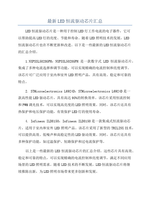
PF/lo/efficiency vs Vin.ac @different Vo(18V, 21V, 24V): W/O dimmer
90 88 86 84 82 80 78 76 74 72 70 105 110 115 120 125
108Vac
120Vac
130Vac
Vin.ac[V]
Io.avg[mA]
Io.pkpk[mA] 103 112 115
rpl%[%] 32.7 31.7 30.1 <=35%
108 315 120 353 132 382 % under Co: 1000uF/35V
COMPANY CONFIDENTIAL
COMPANY CONFIDENTIAL
Key V-I mapping
2. Vin.ac and Iin.ac:
LED load(6LEDs, CREE ML-E), without dimmer
108Vac
120Vac
132Vac
COMPANY CONFIDENTIAL
Key V-I mapping
COMPANY CONFIDENTIAL
Key V-I mapping
1.Fsw vs Vin.dc/Vds: W/O dimmer
@Vds=max @Vds=min
Fsw=63kHz, Ton=5.68us.
Fsw=109kHz, Ton=6.8us.
Yellow-Vds; Green-VIsense
Io vs dimmer conduction angle
400 350 Iout[mA] 300 250
Ploss[W] 0 0.88 0.9 1.0 1.2 1.3 1.4 1.5 1.6 2.0 2.1 2.1 2.1 2.2 2.1
200
150 100 50 0 0.0 2.0 4.0 6.0
Io vs dimmer conduction angle
8.0
10.0
12.0
dimmer conduction time[ms]
COMPANY CONFIDENTIAL
Basic electrical performance
Efficiency/loss vs Vin.ac: without dimmer
@6 ML-E LEDs
Vin.ac[V]
0 30 40 50 60 70 80 90 100 110 120 130 Pin[W] 0 0.4 0.7 1.1 1.7 2.5 3.6 5.3 7.7 8.7 9.6 10.3 Iin[mA] 0 13 18 22 29 36 45 59 77 80 81 82 PF 0 0.985 0.985 0.988 0.992 0.993 0.994 0.996 0.996 0.989 0.98 0.969 Without Triac dimmer Io[mA] Vo[V] Po[W] 0 0 0 1 15.1 0.02 14.3 16.0 0.23 36.6 16.6 0.61 66.5 17.2 1.14 103 17.77 1.83 147.2 18.4 2.70 213 19.14 4.08 294 20.07 5.90 331 20.48 6.78 360 20.84 7.50 385 21.15 8.14 eff.[%] 0 3.8 32.7 55.2 67.3 73.2 75.1 76.9 76.6 77.9 78.2 79.1 Ploss[W] 0 0.4 0.5 0.5 0.6 0.7 0.9 1.2 1.8 1.9 2.1 2.2
SSL2129A 8W[21V0.35A] dimmable Flyback driver for 120/230Vac input
John Zhang Nov. 2012
SSL2129A 8W[21V0.35A] dimmable Flyback driver for 120Vac
COMPANY CONFIDENTIAL
COMPANY CONFIDENTIAL
Basic electrical performance
Efficiency/loss vs conduction angle: with dimmer
@6 ML-E LEDs
Dimmer 120Vac Triac dimmer dimming position:Ton[ms] Pin[W] Iin[mA] PF Io[mA] Vo[V] Po[W] eff.[%] 0.0 0 0 0 0 0 0 0 2.6 1 30 0.271 7.8 15.77 0.12 12.3 3.0 1.2 35 0.283 17 16.12 0.27 22.8 3.5 1.6 43 0.322 37.3 16.66 0.62 38.8 4.0 2.2 45 0.402 60.8 17.14 1.04 47.4 4.5 2.9 49 0.502 92.5 17.67 1.63 56.4 5.0 3.7 56 0.55 125.4 18.13 2.27 61.4 5.5 4.30 57 0.625 154 18.5 2.85 66.3 6.0 5.3 63 0.7 192.7 18.96 3.65 68.9 6.5 7.1 73 0.799 258.4 19.74 5.10 71.8 7.0 7.9 76 0.853 287.5 20.08 5.77 73.1 7.5 8.5 78 0.899 313.6 20.39 6.39 75.2 8.0 8.9 79 0.935 330.5 20.64 6.82 76.6 8.5 9.4 81 0.962 342.6 21 7.19 76.5 10 9.6 81 0.98 360 20.84 7.50 78.2 Io[mA]