DTSD341电能表说明书
威胜DTSD341DSSD331-9D表英文说明书

USER MANUALDSSD331/DTSD341-9DTHREE PHASE ELECTRONIC MULTIFUNCTION ENERGY METERContent1.Overview ......................................................................................................................................................................1.1.Standard.......................................................................................................................................................................1.2.Working Theory ............................................................................................................................................................plate Description..................................................................................................................................................1.4.Technical Parameter .....................................................................................................................................................Basic Technical Parameter ..................................................................................................................................................Calendar Clock ...................................................................................................................................................................Power Impulse....................................................................................................................................................................Other Parameter .................................................................................................................................................................2.Glossary .......................................................................................................................................................................................................2.1.Demand interval............................................................................................................................................................2.2.Maximum demand ........................................................................................................................................................2.3.Sliding window time ......................................................................................................................................................2.4.Peak on, Peak, Peak off, Valley, Low Valley, Lowest Valley time zone.............................................................................2.5.Harmonic voltage(voltage Distortion) .............................................................................................................................2.6.Harmonic current(current Distortion)..............................................................................................................................2.7.Total Voltage Harmonic Distortion(THD U) .......................................................................................................................2.8.Total Current harmonic Distortion(THD i) ....................................................................................................................3.Function Introduction ................................................................................................................................................................................3.1.TOU energy measurement (six tariffs, 4 quadrants)........................................................................................................3.2.Measure current, voltage, frequency and power.............................................................................................................3.3.Calculate M.D...............................................................................................................................................................3.4.Harmonic analyze .........................................................................................................................................................3.5.The record of 12 months account data...........................................................................................................................3.6.The record of load curve ...............................................................................................................................................3.7.Main and Subsidiary Tariff Setting..................................................................................................................................3.8.The record of event.......................................................................................................................................................Loss Phase.........................................................................................................................................................................No load...............................................................................................................................................................................Loss current........................................................................................................................................................................Exceed Voltage limit............................................................................................................................................................Unbalance voltage ..............................................................................................................................................................Reverse..............................................................................................................................................................................Exceed demand..................................................................................................................................................................Power on ............................................................................................................................................................................Reset..................................................................................................................................................................................Three Phase Failure Record................................................................................................................................................Current Reverse Indicator....................................................................................................................................................The record of electronic energy quality.................................................................................................................................The unbalance rate of current..............................................................................................................................................The event of high-neutrality current......................................................................................................................................The exceed limit of current ..................................................................................................................................................Open cover events..............................................................................................................................................................3.9.Freezing Energy ...........................................................................................................................................................3.10.I mpulse output and accuracy check...............................................................................................................................3.11.Other signal output........................................................................................................................................................3.12.D ouble RS-485 communication and optical communication............................................................................................3.13.R eading meter when PT shut down ...............................................................................................................................3.14.B attery..........................................................................................................................................................................4.LCD Description .........................................................................................................................................................................................4.1.LCD display face...........................................................................................................................................................4.2.Description of main display screen. ...............................................................................................................................4.3.Dendrite menu (refers to appendix 1).............................................................................................................................4.4.Description of menu, display screen and the mark..........................................................................................................Main menu..........................................................................................................................................................................Submenu of real time data...................................................................................................................................................Submenu of real time data...................................................................................................................................................Submenu of meter status word ............................................................................................................................................Submenu of history data......................................................................................................................................................Submenu of three phase total energy...................................................................................................................................4.4.8. Submenu of query parameter.......................................................................................................................................Other menu.........................................................................................................................................................................4.5.Alarm information definition...........................................................................................................................................5.Installation and connection ........................................................................................................................................................................5.1.installation dimension and usage...................................................................................................................................5.2.main terminal connect...................................................................................................................................................5.3.Auxiliary terminal connect .............................................................................................................................................6.1.The operation of button (key).........................................................................................................................................6.2.RUN, EVENT and power impulse output........................................................................................................................6.3.parameter setting, clear zero, M.D resetting...................................................................................................................6.4.Change battery.............................................................................................................................................................6.5.leading sealing..............................................................................................................................................................7.Notice ...........................................................................................................................................................................................................7.1.Notice in using time.......................................................................................................................................................7.2.Transportation and Storage ...........................................................................................................................................7.3.Guarantee ....................................................................................................................................................................8.Maintance ....................................................................................................................................................................................................8.1.Free of charge ..............................................................................................................................................................8.2.Free of Duty, on this condition, the service may take cost............................................................................................... Appendix 1: DSSD331/DTSD341-9D meter structure............................................................................................................. Remark: if you know more about display content, you can see 4. LCD display user manual. ................................................... Appendix 2: The manual of display code(Display ID code)...................................................................................................... Remark: if you know more about display content, you can see 4. LCD display user manual. ...................................................1. Overview1.1. StandardDL/T 614-1997 《Multifunction Energy Meter 》GB/T 17883-1999 《Class 0.2S and 0.5S Static AC Active Energy Meter 》GB/T 17882-1999 《Class 2 and 3 Static AC Reactive Energy meter 》DL/T 645-1997 《Multifunction Energy Communication Protocol 》GB/T 15543-1995 《Power Quality Unblance Rate of Three Phase Voltage 》1.2. Working TheoryDSSD331/DTSD341-9D type 0.2s class energy meter use slap-up meter design project: DSP+ management MCU, include DSP and MCU. The working theory is as follow: the 16 bits A/D converter and DSP sample the current and voltage and making relative calculation. The DSP finish the parameter measurement, energy consumption, and harmonic analysis, harmonic energy calculation. All the calculation will be send to MCU through the high speed communication channel, and the MCU will manage the display, data analysis, storage, communication, other function and parameter, the working theory is show in diagram 1.Diagram 1 DSSD331/DTSD341 –9D Working Theory1.3.Diagram 2 DSSD331/ DTSD341 –9 D Nameplate Descriptions1.4. Technical ParameterNote’*’: The built -in Battery is for power supply of built-in clock1.4.3. Power Impulse⏹Meter Constant⏹Impulse Parameter2.1. Demand intervalBe measured time interval that is consecutive-equal for average power.2.2. Maximum demandMaximum value for demand in a special period2.3. Sliding window timeBe measured time interval for M.D by recurrence, the time interval is less than demand interval2.4. Peak on, Peak, Peak off, Valley, Low Valley, Lowest Valley time zonePeak on: The Period of Maximum Load in a dayPeak: The Period of High Loda in a dayPeak off: The Period of average load in a dayValley: The Period of Small Load in a dayLow Valley: The Period of Smaller Load in a dayLowest Valley: The period of Minimum Load in a day2.5. Harmonic voltage(voltage Distortion)U H: Harmonic Voltagen: Harmonic timesU h: the h times harmonic voltage2.6. Harmonic current(current Distortion)I H: Harmonic Currentn: Harmonic timesI h: the h times harmonic current2.7. Total Voltage Harmonic Distortion(THD U)U H: Harmonic voltageU1: Fundamental wave voltage2.8. Total Current harmonic Distortion(THD i)I H= Harmonic currentI1= Fundamental wave current3. Function Introduction3.1. TOU energy measurement (six tariffs, 4 quadrants)Measure total and the energy by 6 tariffs for import/export kWh, kvarh as well as the kvarh of 4 quadrants, the defination of 4 quadrants is described in diagram 3.Diagram 3: Defination of 4 QuadrantsThere are two types of reactive measurement mode as following:1) Import Reactive= Ⅰ Quadrant + Ⅱ QuadrantExport Reactive= Ⅲ Quadrant + Ⅳ Quadrant2) Import Reactive= Ⅰ Quadrant + ⅣQuadrantExport Reactive= Ⅲ Quadrant + Ⅱ QuadrantThese two types of measurement mode can be programed before usage.The accuracy calss for reactive measurement is 0.2S and calss 1.0 for reactive, the reactive accuracy is inspected by follow the standard 《Class 1 and 2 Static AC Active Energy Meter 》Year section (Maximum 14 times): The one year can be devided into several time section which can be applied with different schedule (Maximum 12 times) of day switch times (Maximum 14 times), the tariff for each day switch can be programmed but the maximum number is 6 tariffs. There are special time in a year which can be programmed like the weekend and holiday, customer may set special day switch schedule for these days. Current tariff can be displayed and reviewed on the left buttom of LCD.3.2. Measure current, voltage, frequency and powerMeter can measure voltage & current of each phase and each element, measure total and reach pahse & element kW, kvar, power factor and frequency. The voltage between the virtual center and line for a 3 phase 3 wire meter can be calculated. The distinguish ability for voltage 0.01V, for current is 0.001A, for kW and kvar is 0.0001, for frequency is0.001Hz. The power direction can be indicated by displying the symble “P”, “+”, “-”, “Q” and “1~4”.3.3. Calculate M.DMeter can measure total M.D. of import/export kW & kvar, 4 quadrant kvar with time, and the M.D. can be measured by each tariffs also. The demand interval is programable from 5, 10, 15, 30 and 60 minutes, sliding time is programable from 1, 2, 3 and 5 minutes.3.4. Harmonic analyzeDSP convert the voltage and current signal by FFT in 256 points, then the value, phase of 2~39 times harmonic voltage and current can be calculated out, the accuracy for harmonic value is 2% (for 2~21 times harmonic), the phase accuracy is +1~2 degree. All harmonic information can be displayed on LCD, and the harmonic data storage can be read out through communication port. There are 6 kinds of harmonic date will be stored like: n times harmonic voltage, orginal phase and the harmonic value, n times harmonic current, orginal phase and the harmonic value, total aberrance rate of harmonic voltage, total aberrance rate of harmonic current. The harmonic value can be display on LCD in histogram format.3.5. The record of 12 months account dataMeter can record total and TOU kWh, kvarh, M.D. and M.D time of current month and last 1th to 12th month. The billing time is clock 00:00 from the frist day for each month, and this billing date can be programmed.3.6. The record of load curveThe record mode of load curve can be set through any communication port on meter, there are 8 kinds of data can be record, user may use this date to draw curve for analyse.Definition of 8 kinds of load curveThe memory size of load curve data storage is 4M bytes. The minimum record interval for these data is 1 minute. The data items to be record and the interval are programmable. Meter will start to record each data according to the setting from the pre-set ‘start time’Calculate formula: T =)(LM-∑=91)/(iTiLiT = the record of curve of load time lengthM = FLASH memory (-9D meter memory is 4M)L= Index table length (-9D meter memory is 16.5bytes)Li= Total bytes of the i class dataTi= the setting time interval of i class data3.7. Main and Subsidiary Tariff SettingThere are two tariff settings can be programmed in the meter, current active tariff is main tariff and the subsidiary tariff is backup tariff. The switch time for these two settings can be programmed. And there are different symbles on LCD to indicate the main and subsidiary tariff, ①for main and ②for subsidiary. When meter is running under season tariff, the two symbols will not displayed.3.8. The record of event3.8.1. OutageMeter can record last 10 times of outage time, starting time, times and accumulative total outage time.3.8.2. Loss PhaseWhen the power is on at 3 phases 4 wires mode, if the voltage of 1 phase is lower than ug and the casting time is longer than tu, and the current of the phase is lower than 0.5%IB±0.05%IB,the phase is Power down; When the voltage of Loss-phase goes higher to ug and casting longer than td, the phase resumes. In 3P3W mode, if the total voltage of element A & C lower than 1.2 times of Un, B phase lose phase. If the voltage of element A&C ua-uc|≥u0, and casting longer than tu, and the current of the element lower than 0.5%Ib±0.05%Ib, A phase lose phase. When |ua-uc| is lower than u0, and the casting time longer than td, the phase resume. When loss phase is taking place, happening time, loss phase times and total time will be recorded. Event light will be turned on automatically. After loss phase, ending time will be recorded and alarm will be cancelled.ug: Limited Value for loss phase, can be set up(25V~Un,Un=57V or 100V), default 30V.tu: Loss phase casting time, can be set up(1 min~99 min), default 1 minute.td: Loss phase resume casting time, can be set up(1 min~99 min),default 1 minute.3.8.3. Loss voltageIf the voltage of a loss voltage is lower than 78%Un±2V, the current is higher than 0.5%Ib+0.05%Ib, and cast longer than te, this phase loss voltage. Loss voltage start/end time, meantime power and total time will be recorded, event light turn on. But, when 3P3W, if voltage of element A&C is lower than Uw, it is not loss voltage.When voltage of the phase resumes to 85%Un±2V, and cast longer than tf,timing stops, Loss voltage stops. The meter will record the ending time, meantime power and cancel the alarm.The meter has the function to record all loss voltage events from first time to 10th time, loss voltage times and total times.Besides, the meter recorded the active energy of import/export, metering from the communication port.Un:Limited value for loss voltage, can be set up(20V~Un,Un=57V or 100V),default 57V;Uw:the up limit of voltage failure in three phase three wire system can be set to 20V~Un,Un=57V or 100V, the default setting is 57V;te Loss voltage casting time, can be set up(1 min~99 min),default 1 minute;tf Loss voltage resuming time, can be set up( 1 min~99 min), default 1 minute.3.8.4. No loadIn 3P3W mode, when each current is lower than I0,either the voltage of A or C is lower than I0,it is unload. The Event light turn on, meter records start/end time and total time.I0: Limited value for unload, can be set up(20mA~99mA),default 30mA.3.8.5. Loss currentWhen loading, if the current of a phase Is lower than Ig,and lower than 1/Riof the average of the voltage for another 2 phases, and cast longer than ti, 1 current of the phases is higher than Ik, this phase lost. When the current of the disconnected phase is higher than Ig,and higher than 1/Riof the average of the voltage for another 2 phases and cast longer than tj, this lost current resumed.When disconnected, the meter record the happening time and meantime power, turn on the event light. When resuming, it record the resuming time and meantime power, and cancel alarm. Beside this, the meter record import/export active energy measurement when disconnecting, metering by the communication port.The meter has function to record disconnected current times and total time.Ig: Limited value for disconnected current No 1, can be set up(20mA~99mA),default 60mA;Ik: Limited value for disconnected current No 2, can be set up(20mA~99mA),default 60mA;Ri:the phase current scale factor can be set to 2~50,the default setting is 8;T(i): Casting time when disconnecting current, can be set up(1 min~99 min), default 1 minute.T(j): Casting time when disconnecting current resuming, can be set up(1 min~99 min), default 1 minute.3.8.6. Exceed Voltage limitWhen any voltage of phase is higher than 125%Uh, and casting time≥t(over), this phase exceed limit; When the volt age is 120%Uh or less, and the casting time ≥t(over), exceed limit stops. And it record the start/end time(Month, day, hour and minute) from the first time to 10th and the meantime voltage.Uh: Distinguishing limited value for exceed limit, can be set up (20V~Un, Un=57V or 100V), default 57V;T(over):Casting time when exceed limit, can be set up (1 min~99 min), default 1 minute.3.8.7. Unbalance voltageWhen the voltage of the three phases are unbalanced, and the unbalance rate is bigger than the preset limit, meter will record the unbalance events. When the unbalance rate is lower than the preset limit, the event recording stopped. Meter3.8.8. ReverseThe meter will record start/end time (month, day, hour and minute) of reverse from 1st time to 10th and meantime active power. The symbol ‘Alarm’ will be displayed when this event happened.3.8.9. Exceed demandWhen the average demand of demand cycle ≥ the up limited of demand (can be set up, default 1000W), it is exceed demand. The meter record the demand, exceed demand time, and turn on alarm light; when the maximum demand less than the up limited, exceed demand stops, and the time will be record. Meter can record last ten times events.3.8.10. ProgrammingMeter will record each programming time from 1st time to 10th and the programming mark.3.8.10.1. Power onMeter will record each power on time from 1st time to 10th (month, day, hour and minute).3.8.10.2. ResetMeter will record each reset time from 1st time to 10th (month, day, hour and minute).3.8.10.3. Clear demandMeter will record each clear demand time from 1st time to 10th (month, day, hour and minute), and maximum demand before clear demand.3.8.10.4. Clear zeroMeter will record each clear zero time from 1st time to 10th (month, day, hour and minute), and the active energy before clear zero.3.8.10.5. Calibrate dateMeter will record each time of calibrate date from 1st time to 10th (month, day, hour and minute), and time before calibrate date(month, day, hour and minute).3.8.10.6. Voltage Qualification RateThe up and lower voltage limit is programmable to check the voltage quality, meter will measure the average voltage of every minute than compare with the limit value. The total running time of phase A/B/C when the voltage is in the checking range or exceed the up limit or lower than the lower limit will be record.The up & lower limit of voltage checking range is programmable; the default setting is 0V;The up & lower limit of voltage qualified range is programmable; the default setting is 0V;3.8.10.7. xceed limit of voltage DistortionWhen the total harmonic voltage/current is large than the up limit (programmable, the default voltage setting is 10V and the current is 6A) the aberration event is happened, and meter will record this event with time; when it voltage/current come back and lower than the limit, the event finished, and meter will record the event with time.The last ten time events will be record.3.8.10.8. Three Phase Failure RecordWhen the three phase voltage failed, meter will record this events, the start and end time and current total energy value, meter will make alarm by LED lighting. The voltage failure event for each phase will not record at this moment.3.8.10.9. Current Reverse IndicatorFor three phase four wire connection, when any one phase current reversed, the relative symbol (Ia, Ib, Ic) for each phase with ‘-’ will be diplayed on LCD3.8.11. The record of electronic energy quality3.8.11.1. The unbalance rate of currentWhen the current of the three phases are unbalanced, and the unbalance rate is bigger than the preset limit, meter will record the unbalance events. When the unbalance rate is lower than the preset limit, the event recording stopped. Meter(3P4W)(3P4W)。
湖南威胜DTSD341/DSSD331-1型表说明书

1 综合介绍1.1概述DTSD341/DSSD331-1型V3.4全电子式多功能三相交流电能表,是湖南威胜电子有限公司历经六年开发研制生产的新一代智能型高科技电能计量产品。
它以本公司专利技术为基础,采用IEC 国际电能表标准和国家有关电能表标准设计和制造。
本产品采用大规模专用集成电路和SMT 电子装联生产工艺,为产品实用性和质量奠定了可靠基础。
本产品可同时计量正、反向有功电量,感、容性无功电量,正、反向有功最大需量,具有四费率。
内部具有时钟芯片进行分时计量,可提供本月、上月和总计用电信息,同时具有为防窃电服务的失压电量和失压时间记录功能。
在接口方面,本产品具有校表用脉冲接口,远动用脉冲接口,抄表用数据通信接口,参数设置、抄表电卡接口,以及预付费、负荷监控用继电器输出接口。
本产品的开发、生产、销售质量保证体系于1996年通过了挪威船级社ISO9001认证,并在1995年获得了电力部首批入网许可证。
1.2工作原理本产品由电压、电流互感器,高精度高速专用模-数转换器(A/D),电能计量专用集成电路,实时时钟,不易挥发数据存储器,大画面液晶显示器,开关量接口,数据通信接口,高性能开关电源等电路模件构成。
电压、电流模拟信号通过互感器、A/D 转换等信号处理电路后,进入专用集成电路进行电能量的计算和各项分析处理,其结果保存在数据存储器中,并随时向外部接口提供信息和进行数据交换,其原理框图如图1所示。
图1 工作原理(以三相四线表为例)1.3规格及主要技术参数1.3.1 规格1.3.2 主要技术参数1.4电能表功能简介1.4.1 电能表的基本类型本公司电能表按功能分为两种基本类型:TH 型和TF 型。
TH 型为双方向电能表,计量正、反有功和感、容性无功电量。
TF 型为单方向电能表,计量正向有功和感、容性无功电量,反向有功计量精度不作保证,仅供防窃电参考。
TF 型电能表反向有功有两种计量方式,分别为反向电量计入正向电量中同时反向电量总量单独计量方式和正、反向单独计量方式。
威胜DTSD331 DTSD341-U型三相电子式多功能电能表用户手册说明书

目录1 综合介绍 (3)1.1 概述 (3)1.2技术参数 (3)2、仪表基本功能 (4)2.1.1显示图解: (5)2.1.2、常用显示代码 (6)3 使用注意事项 (8)4 运输贮存 (9)5.质保条款 (9)DTSD341/DSSD331-U三相电子式多功能电能表1 综合介绍1.1 概述DSSD331/DTSD341型三相三(四)线电子式多功能电能表是威胜集团有限公司研制生产的新一代智能型高科技电能计量产品,符合GB/T17215.321-2008、GB/T17215.322-2008、GB/T17215.323-2008 和DL/T614-2007 等电能表有关标准,采用DL/T645-2007通信规约。
1.2技术参数1.2.1主要技术参数项目 技术要求参比电压 3×220V/380V,3×57.7V/100V, 3×100V 电压测量范围 三相80%Un ~ 120%Un电流测量范围 1%Ib~12Ib主要电流规格 互感器接入式:0.3(1.2)A, 1.5(6)A直通式:5(60)A,10(100)A 准确度等级 有功0.2S级 0.5S级、1级 ; 无功2级工作温度 -25℃~60℃极限工作温度 -40℃~70℃相对湿度 ≤95%(无凝露)频率范围 (50±2.5)Hz启动电流 互感器接入式表:2‰In直通表:4‰Ib功耗 <1.5W,6VAMTBF ≥1×10⁵ h设计寿命 10年时钟误差 ≤0.5 s/d(0℃~+40℃时:±2ppm;-40℃~+85℃时:±3.5ppm)时钟频率 1Hz电池寿命 10年电池连续工作时间 ≥5年1.2.3 光耦脉冲输出脉冲输出宽度 (80±5)ms最大允许通过电流 10mA(DC) 工作电压 5V~24V(DC)1.2.4安装尺寸 外形尺寸长×宽×厚=290mm×170mm×85mm图1:安装尺寸图1.2.5主端子接线图(具体以实物为准)三相四线直接接入式接线图C NB A 765324189电源侧负载侧图2:主端子接线图1.2.6辅助端子接线图(具体以实物为准)图3:辅助端子排列图2、仪表基本功能分时计量功能、跨月结算、监测与事件记录功能、最大需量功能、485与红外通讯功能、低功耗功能、辅助电源功能(可选)、安全权限管理、液晶显示功能2.1液晶显示:2.1.1显示图解:液晶全屏图项目液晶上显示内容含义说明电能数据显示行,显示各种记录数据。
威胜DTZ341使用说明书

1 综合介绍1.1 概述DSZ331/DTZ341/DSSD331/DTSD341(配置号为MB3V8.5)三相智能电能表/三相电子式多功能电能表是威胜集团有限公司研制生产的新一代智能型高科技电能计量产品,符合GB/T17215.321-2008、GB/T17215.322-2008、GB/T17215.323-2008 和DL/T614-2007 等电能表有关标准,采用DL/T645-2007通信规约(有扩展)。
1.2 工作原理简述本产品由电流互感器、集成计量芯片、微控制器、温补实时时钟、数据接口设备和人机接口设备组成。
集成计量芯片将来自电压分压,电流互感器的模拟信号转换为数字信号,并对其进行数字积分运算,从而精确地获得有功电能和无功电能,微控制器依据相应费率和需量等要求对数据进行处理。
其结果保存在数据存储器中,并随时向外部接口提供信息和进行数据交换,其原理框图如图1所示。
图1:工作原理简述(以三相四线表为例)1.3 技术参数1.3.2 日历时钟(DS3231SN温补时钟)1.3.3 光耦脉冲输出1.3.4 继电器输出本仪表可以选配“报警”继电器。
“报警”辅助端子为继电器的常开触点。
继电器规格为:直流30V/5A或110V/0.3A,交流250V/5A。
1.3.5 其它数据1.3.6 外形和布局(面板参数以实物为准)液晶显示屏按键1#上盖铅封螺钉按键3#底盒端盖铅封螺钉电池盖上面板指示灯端盖上 盒下透镜按键2#图2:外形布局图1.3.7 安装尺寸图3:安装尺寸图1.3.8 主端子接线图图4:接线图注:辅助电源以仪表端盖上接线图为准。
2 仪表主要功能2.1电能计量功能本仪表具有A、B、C各元件和合元的正向有功能、反向有功、四个象限无功这六类基本电能的计量功能,以及组合有功、组合无功1、组合无功2这三类组合电能的计算功能。
组合有功电能可由正反向有功电能进行选择性加减组合,通过修改有功组合方式特征字进行设置。
威胜DTZ341使用说明书

1 综合介绍1.1 概述DSZ331/DTZ341/DSSD331/DTSD341(配置号为MB3V8.5)三相智能电能表/三相电子式多功能电能表是威胜集团有限公司研制生产的新一代智能型高科技电能计量产品,符合GB/T17215.321-2008、GB/T17215.322-2008、GB/T17215.323-2008 和DL/T614-2007 等电能表有关标准,采用DL/T645-2007通信规约(有扩展)。
1.2 工作原理简述本产品由电流互感器、集成计量芯片、微控制器、温补实时时钟、数据接口设备和人机接口设备组成。
集成计量芯片将来自电压分压,电流互感器的模拟信号转换为数字信号,并对其进行数字积分运算,从而精确地获得有功电能和无功电能,微控制器依据相应费率和需量等要求对数据进行处理。
其结果保存在数据存储器中,并随时向外部接口提供信息和进行数据交换,其原理框图如图1所示。
图1:工作原理简述(以三相四线表为例)1.3 技术参数1.3.4 继电器输出本仪表可以选配“报警”继电器。
“报警”辅助端子为继电器的常开触点。
继电器规格为:直流30V/5A或110V/0.3A,交流250V/5A。
1.3.6 外形和布局(面板参数以实物为准)液晶显示屏按键1#上盖铅封螺钉按键3#底盒端盖铅封螺钉电池盖上面板指示灯端盖上 盒下透镜按键2#图2:外形布局图1.3.7 安装尺寸图3:安装尺寸图1.3.8 主端子接线图图4:接线图注:辅助电源以仪表端盖上接线图为准。
2 仪表主要功能2.1电能计量功能本仪表具有A、B、C各元件和合元的正向有功能、反向有功、四个象限无功这六类基本电能的计量功能,以及组合有功、组合无功1、组合无功2这三类组合电能的计算功能。
组合有功电能可由正反向有功电能进行选择性加减组合,通过修改有功组合方式特征字进行设置。
设置方法参见《DL/T 645-2007多功能电能表通讯协议》相关约定。
两种组合的无功电能可由四个象限的无功电能进行选择性加减组合,通过修改无功组合方式1、2特征字进行设置。
威胜DTZ341使用说明书8.5全解

1 综合介绍1.1 概述DSZ331/DTZ341/DSSD331/DTSD341(配置号为MB3V8.5)三相智能电能表/三相电子式多功能电能表是威胜集团有限公司研制生产的新一代智能型高科技电能计量产品,符合GB/T17215.321-2008、GB/T17215.322-2008、GB/T17215.323-2008 和DL/T614-2007 等电能表有关标准,采用DL/T645-2007通信规约(有扩展)。
1.2 工作原理简述本产品由电流互感器、集成计量芯片、微控制器、温补实时时钟、数据接口设备和人机接口设备组成。
集成计量芯片将来自电压分压,电流互感器的模拟信号转换为数字信号,并对其进行数字积分运算,从而精确地获得有功电能和无功电能,微控制器依据相应费率和需量等要求对数据进行处理。
其结果保存在数据存储器中,并随时向外部接口提供信息和进行数据交换,其原理框图如图1所示。
图1:工作原理简述(以三相四线表为例)1.3 技术参数拟制:扶小飞2010-06-09 图号:OKRW2.702.532SS审核:1.3.4 继电器输出本仪表可以选配“报警”继电器。
“报警”辅助端子为继电器的常开触点。
继电器规格为:直流30V/5A或110V/0.3A,交流250V/5A。
拟制:扶小飞2010-06-09 图号:OKRW2.702.532SS 审核:拟 制: 扶小飞 2010-06-09 图 号:OKRW2.702.532SS 审 核:1.3.6 外形和布局(面板参数以实物为准)液晶显示屏按键1#上盖铅封螺钉按键3#底盒端盖铅封螺钉电池盖上面板指示灯端盖上 盒下透镜按键2#图2:外形布局图1.3.7 安装尺寸图3:安装尺寸图1.3.8 主端子接线图图4:接线图拟制:扶小飞2010-06-09 图号:OKRW2.702.532SS 审核:注:辅助电源以仪表端盖上接线图为准。
2 仪表主要功能2.1电能计量功能本仪表具有A、B、C各元件和合元的正向有功能、反向有功、四个象限无功这六类基本电能的计量功能,以及组合有功、组合无功1、组合无功2这三类组合电能的计算功能。
威胜DSSD331产品说明书
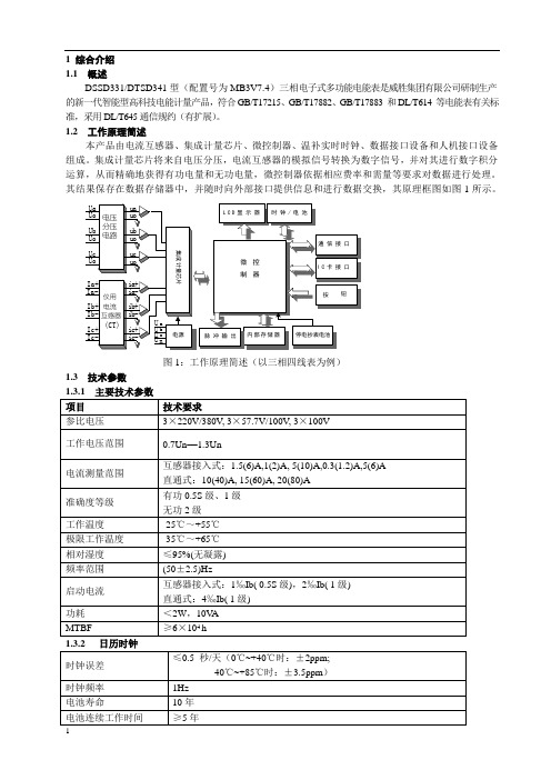
1 综合介绍1.1 概述DSSD331/DTSD341型(配置号为MB3V7.4)三相电子式多功能电能表是威胜集团有限公司研制生产的新一代智能型高科技电能计量产品,符合GB/T17215、GB/T17882、GB/T17883 和DL/T614 等电能表有关标准,采用DL/T645通信规约(有扩展)。
1.2 工作原理简述本产品由电流互感器、集成计量芯片、微控制器、温补实时时钟、数据接口设备和人机接口设备组成。
集成计量芯片将来自电压分压,电流互感器的模拟信号转换为数字信号,并对其进行数字积分运算,从而精确地获得有功电量和无功电量,微控制器依据相应费率和需量等要求对数据进行处理。
其结果保存在数据存储器中,并随时向外部接口提供信息和进行数据交换,其原理框图如图1所示。
图1:工作原理简述(以三相四线表为例)1.3 技术参数1.3.4 继电器输出如果选择了负荷控制功能,将配置“报警”及“跳闸”继电器,“报警”及“跳闸”辅助端子为继电器的常开触点。
继电器的开关能力:纯阻性负载的情况下,220V AC ,130mA1.3.6 外形和布局铅封螺钉锁条有功指示灯下面板下透镜上盒带端子的端子排开盖检测按钮光通信口铁芯无功指示灯远红外指示灯报警指示灯上透镜上面板液晶显示屏底盒端盖铅封按钮按钮电池门按钮按钮铅封螺钉1.3.7 安装尺寸1.3.8主端子接线图注:辅助电源为可选功能,具体接线以表计端盖上接线图为准。
2 仪表主要功能2.1 电量分时计量本仪表有两种配置:TH及TF型(由模式字1的b6设置)。
TH型为双方向电能表,它可以计量正、反向有功,4象限无功以及A、B、C各元件有功、无功电量。
TF型为单方向电能表,它可以计量正向有功,4象限无功以及A、B、C各元件有功、无功电量,反向有功计量精度不作保证,仅供参考。
TH型和TF型电能表都能计量2种组合的无功电量,2种组合的无功电量可由4个象限的无功电量任意组合(通过无功组合模式字设置)。
威胜DSSD331产品说明书
1 综合介绍1.1 概述DSSD331/DTSD341型(配置号为MB3V7.4)三相电子式多功能电能表是威胜集团有限公司研制生产的新一代智能型高科技电能计量产品,符合GB/T17215、GB/T17882、GB/T17883 和DL/T614 等电能表有关标准,采用DL/T645通信规约(有扩展)。
1.2 工作原理简述本产品由电流互感器、集成计量芯片、微控制器、温补实时时钟、数据接口设备和人机接口设备组成。
集成计量芯片将来自电压分压,电流互感器的模拟信号转换为数字信号,并对其进行数字积分运算,从而精确地获得有功电量和无功电量,微控制器依据相应费率和需量等要求对数据进行处理。
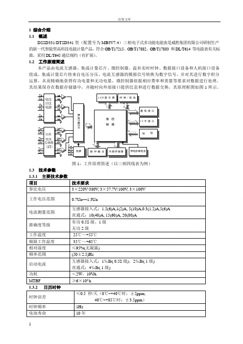
其结果保存在数据存储器中,并随时向外部接口提供信息和进行数据交换,其原理框图如图1所示。
L C D显示器Ia+Ia-Ib+ Ib-Ic+ Ic-仪用电流互感器(CT)ia-ia+ib-ib+ic-ic+微控制器UaUb Uo Uc Uo 电压分压电路Uo uauouououbuc通信接口I C卡接口内部存储器时钟/电池脉冲输出按钮集成计量芯片停电抄表电池电源aUbUUUcn图1:工作原理简述(以三相四线表为例)1.3 技术参数项目技术要求参比电压3×220V/380V, 3×57.7V/100V, 3×100V 工作电压范围0.7Un—1.3Un电流测量范围互感器接入式:1.5(6)A,1(2)A, 5(10)A,0.3(1.2)A,5(6)A 直通式:10(40)A, 15(60)A, 20(80)A准确度等级有功0.5S级、1级无功2级工作温度-25℃~+55℃极限工作温度-35℃~+65℃相对湿度≤95%(无凝露) 频率范围(50±2.5)Hz启动电流互感器接入式:1‰Ib( 0.5S级),2‰Ib( 1级) 直通式:4‰Ib( 1级)功耗<2W,10V A MTBF ≥6×10⁴ h时钟误差≤0.5 秒/天(0℃~+40℃时:±2ppm;-40℃~+85℃时:±3.5ppm)时钟频率1Hz 电池寿命10年电池连续工作时间 ≥5年脉冲输出常数出厂设置以表计面板标识为准。
- 1、下载文档前请自行甄别文档内容的完整性,平台不提供额外的编辑、内容补充、找答案等附加服务。
- 2、"仅部分预览"的文档,不可在线预览部分如存在完整性等问题,可反馈申请退款(可完整预览的文档不适用该条件!)。
- 3、如文档侵犯您的权益,请联系客服反馈,我们会尽快为您处理(人工客服工作时间:9:00-18:30)。
图1:工作原理简述(以三相四线表为例)1.3 技术参数1.3.1 主要技术参数项目技术要求参比电压 3 X 220V/380V, 3 X 57.7V/100V, 3 X 100V工作电压范围0.7 Un —1.3 Un电流测量范围互感器接入式:1.5(6)A,1 (2) A, 5(10)A,0.3(1.2)A,5 (6) A 直通式:10(40)A, 15(60)A, 20(80)A准确度等级有功0.5S级、1级无功2级工作温度-25 C 〜+55 C极限工作温度-35 C 〜+65 C相对湿度< 95%(无凝露)频率范围(50 ± 2.5)Hz启动电流互感器接入式:1 %0 Ib( 0.5S 级),2%o Ib( 1 级)直通式:4%o Ib ( 1级)功耗v 2W 10VAMTBF>6X10⁴ h时钟误差< 0.5 秒/天(O C ~+40C时:土2ppm; -40 C ~+85C时:土 3.5ppm) 时钟频率1Hz电池寿命10年电池连续工作时间> 5年1综合介绍1.1 概述。
$$。
331/。
丁5。
34型(配置号为MB3V7.4)三相电子式多功能电能表是威胜集团有限公司研制生产的新一代智能型高科技电能计量产品,符合GB/T17215、GB/T17882、GB/T17883和DL/T614等电能表有关标准,采用DL/T645通信规约(有扩展)。
1.2 工作原理简述本产品由电流互感器、集成计量芯片、微控制器、温补实时时钟、数据接口设备和人机接口设备组成。
集成计量芯片将来自电压分压,电流互感器的模拟信号转换为数字信号,并对其进行数字积分运算,从而精确地获得有功电量和无功电量,微控制器依据相应费率和需量等要求对数据进行处理。
其结果保存在数据存储器中,并随时向外部接口提供信息和进行数据交换,其原理框图如图1所示。
Ua Uo Ub UoUc Uo la+ la-Ib+ Ib-Ic+ lc-电压分压电路仪用电流互感器(CT)uauoia+ria-ib+ Hl b-LCD显示器时钟/电池I C卡接口ic+停电抄表电池脉冲输出内部存储器ucuoub ruo通信接口集成计U a弋冏电源脉冲输出常数出厂设置以表计面板标识为准。
对 1.5(6)A的电表,通常设为:3 X 220V/ 380V的低压表:有功:2000imp/kW・h 无功:2000imp/kvar • h3 X 57.7V/100V, 3 X 100V 的高压表:有功:5000imp/kW-h无功:5000imp/kvar • h脉冲输出宽度(80 ± 5) ms最大允许通过电流10mA(DO工作电压5V〜24V ( DC1.3.4 继电器输出如果选择了负荷控制功能,将配置“报警”及“跳闸”继电器,电器的常开触点。
继电器的开关能力:纯阻性负载的情况下,220VAC, 130mA其它数据外形尺寸长X 宽X 厚=255mn X 175mn X 85mm净重约 2.4kg 1.3.6 外形和布局“报警”及“跳闸”辅助端子为继下透镜开盖检测按钮下面板铅封按钮锁条电池门铅封螺钉端盖带端子的端子排1.3.7 安装尺寸1|2|34 567 89||1'= \ r 辅助电源4 .4入A入C压.电流互感器接入三相三线经电式接线图注:辅助电源为可选功能,具体接线以表计端盖上接线图为准。
2仪表主要功能 2.1电量分时计量本仪表有两种配置:TH 及TF 型(由模式字1的b6设置)。
TH 型为双方向电能表,它可以计量正、 反向有功,4象限无功以及 A B 、C 各元件有功、无功电量。
TF 型为单方向电能表,它可以计量正向有 功,4象限无功以及 A B 、C 各元件有功、无功电量,反向有功计量精度不作保证,仅供参考。
TH 型和TF 型电能表都能计量 2种组合的无功电量,2种组合的无功电量可由 4个象限的无功电量 任意组合(通过无功组合模式字设置) 。
各种总电量均可以按最大 8种费率时段进行分时计量( A B 、C各元件的电量不分时计量)。
本表计可设置主副两套时段。
电表是否进行主副两套时段切换,受电表模式字 3的b6位控制。
每套时段最大8费率。
每套时段可设置最大 10个年时区切换数,最大 8个日时段表,每天最大 14时段切换。
每套时段可设置 90个公共假日,可设置周休日时段。
百年日历、时间,闰年自动切换。
注意,如果时段表中某一时段的费率号大于费率数时(设置错误) ,此时段的电量计入费率1。
电量显示小数位数设为 2时: 有功电量,最大累计电量为799999.99kW.h 。
对于无功电量,最大累计电量为土799999.99kvar.h 。
电量为负值可能发生在组合无功电量中,由于考虑到电量可能为负,数据设计为带符号,正数范围 0.00 — 799999.99,负数范围:0.00 ―― 799999.99。
反向有功电量是否计入正向有功电量由模式字2的b2确定。
广1册1 i 1■ *n-T\T 11输-U,1 [辅助电源1二^输 三相四线经电丿------------------------------ ■ 1 --------------- -----玉.电流互感器接入式接线图AC8环 266V岫r| ■ ■■ ■ ■ W|-1.3.8主端子接线图三相四线经电流互感器接入式接线图输 入通信软件在解析和设置电量时必须与电表的电量显示小数位一致。
2.2 最大需量分时计量TH型电表可计算正、反向有功、输入无功(I +n)及输出无功(川+W)最大需量及其出现时间(年月日时分);TF型电表可计算正向有功、输入无功(I +n)及输出无功(川+W)最大需量及其出现时间(年月日时分)。
两种配置均可以计量8种费率的最大需量及其发生时间。
最大需量的积分周期和滑差步进时间可选择,滑差时间只能设置为1、2、3、5、10分钟,需量周期与滑差时间的设置必须满足下述关系:1 < (需量周期十滑差时间)< 15,且需量周期能被滑差时间整除。
需量与时钟同步,且掉电时间小于需量周期时掉电期间需量连续(有停电抄表电池时),掉电期间需量是否连续,由模式字3的b3控制,b3 =1 :连续,b3=0:不连续。
2.3 跨月结算本表存储了上1月到上13月的历史数据(包含正反向有功、组合无功1和组合无功2、四象限无功的总电量以及分时电量,正反向有功、输入输出无功的最大需量及其出现时间,各元件有功、无功电量)跨月结算时,先把本月的电量、最大需量及其发生时间存入上月,再把本月的最大需量及其发生时间清零,计算需量的累加单元清零,需量重新开始计算。
如果电表掉电跨过结算日、时,上电后电表将进行跨月结算,跨过几个月,结算几个月。
但跨过13个月后,电表不结算。
2.4 测量功能本仪表测量总及A、B、C各相的电压、电流、视在功率、有功功率、无功功率、功率因数及电网频率,并且显示功率的方向。
无功功率1秒或无功最大功率2级0.01 kvar0.001kvar0.0001kvar由功率小数位确定0.01 kvar功率因数1秒0.0010.001频率1秒47.5—52.5Hz0.0001Hz0.01Hz相角1秒0 —360 °0.01 °0.1o三相三线表中,①a等于Uab与la的夹角,①c等于Ucb与Ic的夹角,①b被强制置为零。
2.5显示功能本仪表米用STN液晶显示、带背光、并有丰富的汉字提示,显示直观、视角宽。
液晶全屏图:lli i____iH那腑瀕叫丨" 制订||忖液晶上各种符号的含义:液晶上显示内容数据显示行,显示各种记录数据。
显示电能数据时,小数位数为2,将显示6位整数、2位小数;小数位数为3, 将显示5位整数、3位小数,每屏显示1个时段的电能d.# ・■ ■■■ ・■■] ■■■ ■ ■■ ra・■|!ABGN上本上井躺入反正向需电钢间剽Qoii喘T过號出无有功失压勰功割尸二-OSI'/ \ '/~~\c* 才f爭'h 匕计、広、-»/•、:L 養、T'd尖峰平谷]恳云舒A [B0崭财冬创聲井遁换D 口口口齐j I bi.F- . ri1n [ s r二O.'O 二:<~v ■30EUa Ub 叫匸尸= ==■=]含义说明2.6通信功能电表具有3个独立的物理通信口: 第一路RS485口、第二路RS485 口、吸附式红外与远红外口 (共 用)。
两个RS485口通信地址互相独立,波特率可在 1200bps 、2400 bps 、4800 bps 、9600bps 间改变,吸附式红外波特率固定为 1200bps ,远红外口波特率固定为1200bps 。
吸附式红外和远红外通信地址与第一路 RS485相同。
2.6.1 .第一路 RS485为主RS485 口,可进行读写操作。
2.6.2 .第二路RS485一般为读操作,通过程序在第一路 RS485 口或红外口设置后也可以进行写操作。
吸附式红外与远红外口可进行读写操作。
停电后,停电抄表电池给电表供电, 电表运行在睡眠状态。
电表在睡眠状态下被唤醒后是否可进行远红外抄读,受模式字控制(模式字2的b1)。
2.6.3.缩位抄表在单表通信时,无论表的通信地址是什么,只要输入12个“A ”作为通信地址就行了。
在多表通信时,取通信地址后 3位,前面全用 A 替换即可。
如:123456789123,只要输入 AAAAAAAAA12即可。
但在设置参数时最少保留3位通信地址。
2.6.4 .广播校时有不带密码的广播校时和带密码的广播校时 2种方式,由模式字1的b4决定。
约束条件:每天只能校 1次,范围在电表时间的正负注意:打包抄表时,费率数为 k ,返回总及费率2.6.5 .辅助电源(可选功能)供电时,电表支持 2.7事件记录功能所有电网运行事件记录的起始条件和结束条件都连续判断 30秒(逆相序为10秒)。
所有电网类事 件记录,在遇到掉电时,都无条件的结束当次事件。
对于所有电网类事件记录, 如果下面两个条件同时满足, 将已经发生的电网事件记录结束, 对于没 有发生的事件记录不再判断;如果有任意一条不满足,则正常判断和记录电网事件记录。
(1)当单相最大电压低于70%Un (2)三相电压之和减去 10V 后的结果低于70%Un失压:失压判断阈值: NN,XX.XXXX NN 指电压百分比阈值, XX.XXXX 指电流绝对值阈值(单位 A )。
(NN,XX.XXXX 可设置)失压分类:三相四线表分为 A B 、C 、AB AC BG ABC 共7种,三相三线表分为 A B 、C 、AC 共4种。
起始条件:电压低于 NN%U ±2V ,电流大于 XX.XXXX (单位:A )。