GPS车载机配置工具使用手册
车载GPS导航仪使用说明书
车载GPS导航仪使用说明书尊敬的用户,欢迎您购买并使用我们的车载GPS导航仪。
本使用说明书将为您提供详细的操作指南,以帮助您正确使用导航仪并获得最佳的导航体验。
一、产品概述车载GPS导航仪是一种基于全球定位系统(GPS)技术的导航设备。
它结合了卫星定位、地图数据库和导航软件,能够为您提供准确的车辆位置信息、路线规划以及导航指引等功能。
我们的产品具有以下特点:1.高精度定位:通过接收卫星信号,导航仪能够实时准确地定位您的车辆,提供精准的导航服务。
2.多功能导航:除了常规的驾车导航功能外,导航仪还提供步行、骑行等多种导航模式,并支持POI(兴趣点)搜索、线路规划等功能。
3.智能语音提示:导航仪内置语音合成技术,能够实时播报导航指引,让您无需分心看屏幕,更加安全便捷地进行导航。
二、使用方法1.前期准备在第一次使用前,请确保您已经将导航仪的电源充满,并正确插入车载支架。
您还需要安装地图数据,可通过我们提供的软件或者在线下载的方式进行。
2.开机与关机长按开关键一秒钟,导航仪即可开机启动。
在正常使用过程中,您可以通过点击界面上的关机按钮进行关闭。
3.地图操作使用触摸屏幕或者外部键盘进行地图操作。
您可以通过手势缩放、平移等方式调整地图显示区域。
另外,点击地图上的兴趣点或者目的地图标,即可进行相关操作,如导航规划、查看详细信息等。
4.导航设置导航仪提供了丰富的导航设置选项,您可以根据个人需求进行调整。
例如,您可以选择偏好路线、避开拥堵、设置声音提示等。
5.语音指引导航仪通过内置扬声器进行语音指引。
在导航过程中,您会听到详细的导航提示,包括转向指示、距离提示等。
您还可以根据需要调整音量大小或者关闭语音指引。
6.兴趣点搜索导航仪允许您搜索周边的兴趣点,如餐馆、加油站、酒店等。
您可以直接在搜索框中输入关键词,系统会为您提供相关的搜索结果,并进行导航到达。
三、常见问题与解答1.为什么导航仪无法定位?请确保导航仪在开放的区域使用,避免遮挡。
车载GPS定位器TK116说明书
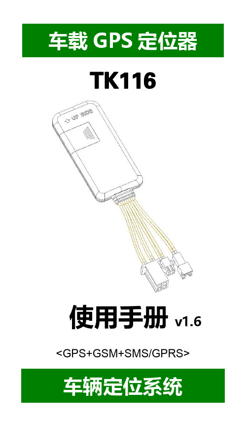
----TK116使用手册v1.6<GPS+GSM+SMS/GPRS>-车辆定位系统--目录一、产品功能、规格 (5)1.1产品功能 (5)1.2产品规格 (6)二、产品结构、配件 (7)2.1产品结构 (7)2.2产品配件 (8)三、安装SIM卡 (9)3.1安装前的准备 (9)3.2SIM卡的安装 (9)3.3取出SIM卡 (10)四、终端安装 (11)4.1安装设备到车辆 (11)4.2终端如何接线 (12)4.3继电器接线 (16)4.4安装麦克风 (16)4.5安装SOS求救按钮 (17)五、开启/关闭终端 (17)5.1开机 (17)5.2状态指示灯 (17)5.3关机 (18)六、查询、监听、切断/恢复油路..186.1短信查询 (18)6.2终端服务平台查询 (18)6.3终端监听 (19)6.4切断/恢复油路 (19)七、终端配置 (20)八、终端报警 (20)8.1振动报警 (20)8.2碰撞/跌落报警 (20)8.3速度报警 (20)8.4位移报警 (20)8.5电子围栏报警 (21)8.6剪线报警 (21)8.7低电报警 (21)8.8SOS报警 (21)九、故障排除 (22)9.1无法连接服务平台 (22)9.2后台显示离线状态 (22)9.3长时间不定位 (23)9.4定位漂移严重 (23)9.5指令接收异常 (23)十、保修细则 (24)10.1特别声明 (24)10.2保修期 (24)10.3售后服务 (24)Warranty Card/保修卡 (25)感谢您选用购买本机器,请您在使用之前认真阅读本说明书,以便得到正确的安装方法及操作指南,以下描述中终端等同于本机器。
产品外观及配色如有改动,请以实物为准,恕不另行通知。
TK116车用定位跟踪产品借助GPS卫星定位系统、GPRS通信和互联网,通过强大的服务平台可以实现对车辆进行实时远程监测和控制作用。
帮助客户实现透明管理、降低成本、保障安全、提高效率的目标。
GPS BDS双系统车载组合导航模块 atgm332d-5s 用户手册说明书

GPS/BDS双系统车载组合导航模块ATGM332D-5S用户手册杭州中科微电子有限公司杭州市滨江区江南大道3850号创新大厦10楼电话:*************传真:*************网站:版本更新历史目录1功能描述 (4)1.1概述 (4)1.2产品选购 (5)1.3性能指标 (5)1.4模块功能框图 (6)1.5应用领域 (6)1.6辅助GNSS (6)1.7 1PPS (6)1.8输出协议 (6)1.9 FLASH (7)1.10在线升级功能 (7)1.11天线 (7)1.12上位机工具 (7)2技术描述 (8)2.1外观尺寸 (8)2.2 PCB layout (9)2.3 PIN 排列图 (10)2.4管脚定义 (11)2.5电气参数 (12)2.6技术规范 (13)2.7模块应用电路 (14)2.7.1有源天线应用方案 (14)2.7.2无源天线应用方案 (15)2.8模块硬件使用事项 (16)2.9模块坐标系 (16)2.10车辆姿态..................................................................... 错误!未定义书签。
2.11模块安装 (17)2.12模块初始化 (17)2.13备份电源启动 (17)3可靠性测试与认证 (18)3.1 RoHS认证 (18)4模块传送与焊接 (18)4.1模块包装 (18)4.2模块传送与存储 (19)5模块标签与下单型号 (20)5.1模块标签 (20)5.2型号命名规则 (20)5.3通用订单型号一览 (21)5.4定制订单型号 (21)参考文献 (21)1功能描述1.1概述ATGM332D-5S系列模块是车载航位推算模块,该模块集成GNSS接收机、6轴惯性传感器,能够为道路行驶车辆提供连续的高精度3D定位。
该系列模块产品都是基于中科微第四代低功耗GNSS SOC单芯片AT6558设计,支持多种卫星导航系统,包括中国的BDS(北斗卫星导航系统),美国的GPS,俄罗斯的GLONASS,日本的QZSS以及卫星增强系统SBAS。
GPS系统监控软件使用说明书

一、本调度软件是在车载机硬件安装完工后,在您的计算机上安装的跟车载机硬件相结合使用的软件(GPS/GSM综合GPS系统用户调度软件),打开调度软件输入GPS运营商提供的有效用户名与密码,登陆到监控系统监控调度车辆界面。
如下图:二、1、调度软件第一个菜单“系统”:a) 登陆与注销:打开菜单栏系统菜单下点击“登陆”,输入用户名跟密码进入监控调度软件正常连接状态界面;(如上图)。
点击“注销”,直接注销登陆账号,退出监控调度软件不连接状态而不退出监控调度软件。
b) 修改密码:打开菜单栏系统菜单下的“修改密码”根据提示输入您要改的密码然后点确定,更改您的登陆密码成功。
(如下图)c) 其他功能菜单一般情况下都不用管它,都采用默认状态。
2、调度软件第二个菜单“监控管理”a)更新设备信息:点击可以更新监控调度软件上的所有车辆的修改显示状态。
b)数据下载:是针对前些时段您没有看车辆的行驶状态的,进行数据下载,下载好数据后可以进行回放前些时段您没看的车辆的行驶状态。
数据下载有三种选择方式:一种是全部数据,包括车辆停车、行走等全部状态的数据,第二种是有状态变化,是车辆有状态变化的数据,第二种是有速度,是车辆行走有速度状态的数据。
如下图:c)历史回放:是针对你前些时段没看车辆的行驶状态而进行数据下载后所作的操作功能,数据下载后进行历史回放您车辆前些时段所行驶的路线轨迹。
历史回放有两种选择方式:一种是有速度变化的数据回放,另外一种是全部数据状态的回放,包括车停止、行走等全部数据回放。
如下图d)客户咨询:一般情况用不到,如果您有什么可以直接联系公司售后客服部。
e)里程查询:针对车辆的里程统计查询。
数据下载后可以里程统计查询您车辆所行驶的里程采集点数和里程公里数,并可以数据导出与打印备份。
如下图:f)车辆停车查询:是对车辆停车状态的查询,数据下载后进行车辆停车查询,可以看到您车辆的停车时间、发动时间、停车详细地址的状态,并可以数据导出与打印备份。
CCTR-801A 803 800车载GPS卫星定位追踪器使用说明说明书

CCTR-801A/803/800车载GPS卫星定位追踪器使用说明欢迎使用CCTR-801A/803/800车载GPS卫星定位实时追踪器,该产品集成了GSM和GPS模块,使用GPS获得经纬度位置信息并利用GSM网络把轨迹传到网络服务器上,客户在任何时候任何地点登录网站即可查询车辆的现在位置及回放历史轨迹,并可设置多种报警模式,如超速报警、超越区域报警,还具有车辆进行断油断电控制功能、监听车内声音功能、防抢防劫的紧急报警功能、内置可充电备用电池在系统断电时可自动报警、附送的魔术贴很容易安装固定,CCTR-800更有磁铁及防水设计,适合特殊场合及功能需求。
本设备安装极为简单,接上电源插上电话卡即可工作,无需任何设置。
另外此设备还提供了手机短信查询位置文字描述的功能,方便紧急使用。
此系统设计小巧、安装简单、使用方便,是公用车辆监控、管理、防盗的理想选择。
访问我公司提供的定位平台网站,选择中文版,使用出厂每台设备预设的用户名和密码即可对设备进行操作及显示当前位置,无需下载安装任何软件。
(出厂预设的网站登录用户名为设备后面条码纸上的S/N串行号码的后六位,密码与用户名相同,用户可自行修改密码,如要修改用户名请致电售后服务电话或代理商由后台管理员修改)本产品可以用做于公司车辆、货运车辆、客运车辆、出租车、公交车、长途客货车、公用车辆、政府公车、私家车、摩托车、电动车等,在管理公司车辆(数量多于一台)时,可以组建一个车队,使用管理员身份(车队管理员用户名和密码要向我公司申请)登陆服务平台,即可看到整个车队车辆的信息并可以对整个车队进行操作管理。
平台网址:1.标准配件1.1标准配件:CCTR-801A/803主机及配线、SOS 紧急报警按钮、使用说明书一份,CCTR-800另有配置车充和电源转换器。
CCTR-800电源控制盒USB 充电线车用充电器CCTR-801ACCTR-8032.使用入门2.1SIM 卡(电话卡)使用说明:本产品使用GSM 网络的手机SIM 卡,在安装之前请确认该SIM 卡已经开通来电显示、短信功能和GPRS 功能。
GPS汽车轨迹器用户手册说明书

GPS Vehicle TrackerUser ManualFor Car,Motorcycle,Truck,Bus etcPlease read the manual carefully before use,so that you can install the device correctly and activate it quickly on the internet.The outlook and true color are subject to the actual product.Web server platform:/Skins/DefaultIndex/Default_en.html?locale=en&back=true Demo account:gwxyPassword:1234561.Accessories:2.Technical parameter1).GSM:850/900/1800/1900Quad band 2).GPRS:Class12,TCP/IP3).Working Voltage:9-90V DC4).Working current:≈22mA(12vDC) 5).Working current:≈12mA(24vDC)6).GPS locating time:Cold start≈38s(Open sky)Warm start≈32sHot start≈2s(Open sky)7).GPS Precision:10m(2D RM)8).Working temperature:-20℃~+70℃9).Working humidity:20%~80%RH10).Measurement:78(L)×27(W)×15(H)mm3.Out look4.Device status indicators(Save power mode) GPS LED Indicator-YellowSolid yellow Searching GPS signalFlashing GPS working normallyOFF Sleep modeGSM LED Indicator-BlueSolid Blue No GSM signal or SIM card not be recognized Flashing quickly(interval0.1s)GSM data transportingFlashing slowly(interval2s)GSM working normallyPower LED Indicator-RedSolid Red Working power from vehicleFlashing(interval1s)Device low batteryOFF Working power from device built-in battery5.Installation5.1Prepare installation(1)ProductCheck.Open the packing box and check the device‘s model and accessories. If the model is wrong or the accessories not complete,please contact the dealer.(2)Choose SIM card.Please take dealer’s advice as reference before insert SIM card.(3)SIM card installation.Insertthe SIM card(as follows).(4)Putback the front cover and screw it up.(5)Connect the device to the9-24Vpower supply.(the red LED constant glow)(6)Install the device in the hidden place of the car;The SIM card must be with GPRS function and enough credit.If your SIM card need input PIN code when power on,please refer to the mobile phone user manual to cancel it5.2InstallationThe GPS tracker must be installed by professional person:(1)Please install the device in the hidden place as followings:-Under Front windshield;-In the front instrument panel;-Under back windshield;(2)Avoid being placed with signal radiators like reverse sensor;(3)The device has built-in GSM and GPS antenna.Please ensure thereceiving side of the device is face up and without metal cover.Note:The metal cover will lessen the GPS signals receiving.6.Device wiring requirements6.1The device power supply is DC9-100V.The red line is positive pole while the black line is negative pole.6.2The negative pole of power supply connects with ground or the metals.Please do not connect with other ground lines.6.3After finished the power supply wire connection,please plug the power supply wire into the device.7.The Device Working7.1Power on:The device will be powered on when detect the current.Then the three LEDindicators will light on continuously.The device will upload the data to the online platform (The uploading data default interval is 10seconds).When the car is in static state for a long time,the device will switch to energy saving mode.7.2Power off :Pull off the power wire to power off the device.Optional MIC and SOS wiring diagram7.3Feature list:er SMS TEXT Settings(1)Set Admin NumberSMS TextCommandParameter SampleAdd Number 710#number#711#number#710#135****5000#711#138****8000#Delete Number D01#D02#D01#D02#Command Description 1)Admin number can control the oil,power and resume factory settings2)Admin number can receive the alarms call and text of vibration,over speeding,out geo-fence,etc3)SIM must display the income call number to control oil and power.4)Only two number can be set as admin number.5)Resend the command to change admin number.CommandFeedbackSuccessful Setting:Add admin account1OK!(2)Check Admin NumberSMS TextCommandParameter Sample Check901#901# CommandDescriptionView the device admin number directly.Command Feedback Successful Setting:Admin1:135****5000,Admin2:138****8000(3)Set Authorization NumberSMS TextCommandParameter SampleAdd Number101#number#102#number#103#number#101#135****5000# 102#12345678912# 103#12345678913#Delete Number D11#D12#D13#D11#D12#D13#Command Description 1)Authorization Number used to control oil by SMS2)Only three number can be set as authorization Number3)Before change the authorization Number should delete previous number first.CommandFeedbackSuccessful Setting:Add Authorization account1OK!(5)APNTextcommandParameter SampleAPN Setting 802#username#password1:802#internet#123#123#2:802#internet#Command Description APN differs according to the local telecommunication operators.For example:If APN request password,please refer to Sample1,Sample2for no password.Command Feedback Successful Setting:apn setting OK!(4)Check authorized numberSMS TextCommandParameter Sample Check C10#C10# CommandDescriptionCheck the device authorization number directly.Command Feedback Successful Setting:Authorization1:135****5000Authorization2:12345678912Authorization3:12345678913(6)Set/View SERVER HOSTSMS TextCommandParameter SampleSERVERHOSTParameter803#SERVER#port#803#58.61.154.231#7018#ViewSERVERCIP#1)CIP#Command Description Change the IP and port when move to a new server port:10~65535.1is domain and0is IP;Command Feedback SERVER Successful Setting:The setting of HOST NAME is successful! HOST:SERVERPORT:7018CIP#Successful Setting:IP:58.61.154.231Port:7018(7)TIMMER(Set data uploading time interval while car is MOVING) SMS TextCommandParameter Sample TIMEERsetting730#uploading interval#730#20#Command Description Time setting scope:10~3600seconds;20means time interval,the default value is15seconds!CommandFeedbackSuccessful Setting:Set upload move ITV20seconds,OK!(8)Alert on/offSMS TextCommandParameter Sample Alert onCommand911#911# Alert offCommand910#910#Command Description This command is used to set the alert on/off,in case of unknown movement or shake.Command Feedback 911#Successful Setting:Defence setting,OK!910#Successful Setting:Cancel Defence setting,OK!(9)STATIC(Set data uploading time interval while car is STATIC) SMS TextCommandParameter SampleSTATIC SUP#time interval#SUP#5#Command Description Time scope:1~1440minutes;The device has3D transmission and the default time interval is5minutes.CommandFeedbackSuccessful Setting:Set upload still ITV5Mins,OK!(10)Cancel the continuous uploadingSMS TextCommandParameter Sample NUP NUP#NUP#Command Description This command is used to cancel sending data to the platform.If need to restore the uploading,need to reset TIMEER or STATIC ParameterCommandFeedbackSuccessful Setting:Close upload gps information OK!(11)RELAY(Remote cut off fuel/power)SMS TextCommandParameter SampleRELAYParameter1222#222#cut off fuel and power RELAYParameter2333#333#recover fuel and powerCommand Description 1)RELAY control the ON/OFF of the vehicle relay;2)Only admin number can set this parameter.3)Only cut off the oil circuit while vehicle driving speed below20KM/H or in static state.4)When send the command,the vehicle speed is over 20KM/H,device will reply“please waiting”Command Feedback 222#Successful Setting:Oil is cut off! 333#Successful Setting:Oil is restore!(13)VIBRATIONSMS Text Command Parameter SampleVIBRATION Alarm Parameter 123#2#,alarming way#1)123#2#1#2)123#2#2#3)123#2#3#Set the vibration alarmtime intervalV123#1#V123#1# Cancel vibration alarm456#456#Command Description Vibration sensitivity level is from1to5,1is the most sensitive and0is close.Alarming ways:1calling,2:text,3:call and text.Must set the admin number and receiving number.Command Feedback Successful Setting:shock setting,OK!way:1shock interval setting,1Mins,OK! noshock setting,OK!(12)GMTSMS TextCommandParameter SampleGMT 801#location,time#801#E8#Command Description The default time zone is Beijing time.If need change, please operate according to the above command.CommandFeedbackSuccessful Setting:time zone ok!(14)OVER SPEED ALARM SETTINGSMS TextCommandParameter SampleSPEED Parameter SSA#120#alarming way#SSA#120#1#Command Description Speed range:60-220,if not inside this range,the alarm off.Alarming way1:call,2:text,3:call and text. Must set the admin number and receiving number.CommandFeedbackSuccessful Setting:Speeding Alarm setting,OK!(15)RESETSMS TextCommandParameter SampleRESET930#930#CommandDescriptionReset the deviceCommandFeedbackSuccessful Setting:Reset system,ok!(16)FACTORY RESTORESMS TextCommandParameter SampleParameter940#940#CommandDescriptionRestore the factory setting,only admin number can set. CommandFeedbackSuccessful Setting:Factory,OK!(17)LANGUAGE SETTINGSMS TextCommandParameter SampleLANG Parameter LANG1#LANG0#LANG1#LANG0#Command Description Set the language of command feedback,LANG1is Chinese,LANG0is EnglishCommandFeedbackSuccessful Setting:Set language,OK!(18)WHERE(Optional)SMS TextCommandParameter Sample WHERE988#988#Command Description Check the longitude and altitude and other information of the deviceCommandFeedbackReply with longitude and altitude,speed and IMEL.(19)URLSMS TextCommandParameter Sample WHERE666#666# CommandDescriptionCheck the location link of Google mapCommand Feedback GPS!Lat:22.66349long:114.22066,speed:000.0T:04/19/1913:47Location URL:/maps?q=N22.540885,E113.95265(20)PARAM(Device details)SMS TextCommandParameter Sample PARAM886#886#Command Description The command is to check the settings or the default parameter.Command Feedback IMEI:351190012535936 APN:cmnetIP:58.61.154.231 PORT:7018 LANGUAGE:English TIMEZONE:E8 NUMBER INFOR SOS:135****5000 ADMIN1:135****5000 ALARM WAY:1BAT VOL:12.73V(21)STATUSSMS TextCommandParameter SampleSTATUS902#902#CommandDescriptionDesigned for checking the device’s working status.Command Feedback IMEI:353327022096317Basic informationVERSION:61M-Q3_T3-HS-SLW-XY_V2.6_190402 RSSI_LEVEL:83APN:cmnetIP:58.61.154.231PORT:7018PROTOCOL:TCP/IPGPS informationGPS moving report intervals:20secstatic report intervals:5minGPS:UNFIXEDGPS Satellites:0NUMBER INFORSOS:136****5118ADMIN1:136****5118ALARM WAY:3BAT VOL:12.73VOptional functions of one way calling and SOS SMS TextCommandParameter Sample One waycallingSSS#SSS#Command Description Designed for checking the device’s surrounding status. After send the text“SSS#”to the device SIM card number, the device will immediately call back to you.SOS Press the SOS button for more than3s,device will call the admin number immediately in circles until the call will be picked up.Note:Should set the admin number by setting “710#number#”or“711#number#”first.9.Trouble shooting9.1The device is unused or offline on the web server platform9.1.1First,please check the three LED working state.If possible,callthe device’s SIM card number to check:①If the call can not connect to device and feedback the device is notin the GSM service area,please get the GSM signal first.②If reminding the device SIM card is out of fee,please top up the SIM card.③If calling can connect to device,means the SIM card still have fee inside,please check with the SIM card operator that the GPRS function has been opened or not.④If the call can not connect to device and feedback the device waspowered off,please take the device back to analysis as below:a)If the Red LED and blue GSM LED are solid light on,please check theinstallation status of SIM card,if installation no problem,change a new SIM card to retest.b)If the Red LED is off,please check the power terminal wiring isdisconnected or the power line end fuse is blown.Also can use a multimeter to measure the voltage of the main power2P connector.If the voltage is normal,please send the device to the factory for repair.9.1.2Please check there is how many offline devices in the same area,inorder to judge whether its the SIM Card operator’s network problem or not.9.2When GPS cannot receive the signals,please drive to a open skyplace,and ensure there is no metal cover on the device.9.3When the device cannot receive the GSM signal,please check the SIMcard installation.If the GSM signals cannot reach your location(such as the basement),please drive to a open sky place.9.4The red LED can not power on.Check fuse,if its broken,please replace the fuse.。
NYItech NT-183W G 车载定位跟踪终端用户手册说明书
NT‐183W/G用户手册V1.1目 录1. 产品介绍 (3)2. 技术指标 (4)2.1外部接口 (4)2.2状态指示 (4)2.3技术参数 (5)3. 设置参数 (6)3.1PC T OOL参数设置 (6)3.2短信维护指令 (6)4. 安装指南 (7)4.1安装SIM卡 (7)4.2OBD接口 (8)4.3安装终端 (9)5. 产品功能 (11)5.1通信协议 (11)5.2OBD/GPS/G-S ENSOR综合数据上传 (11)5.3远程故障诊断 (11)5.4睡眠固定上传 (11)5.5盲区存储/补报 (12)5.6行驶里程,行驶油耗,行驶时间统计 (12)5.7警情和事件 (12)5.8短信报警 (12)5.9谷歌地图链接 (12)5.10短信设置和维护 (12)5.11本地设置和维护 (12)6. 免责声明 (13)7. 产品保修 (13)8. 声明 (14)产品介绍NT183W 是一款具有定位跟踪,车况检测,驾驶分析功能的车载终端,即插即用,插接于汽车诊断接口上,能够实时获取车辆位置信息,实时车况数据和故障信息,实时驾驶行为数据,并通过无线3GWCDMA 网络,实时上传这些数据至指定的服务器端口,服务器平台软件可以对这些数据进行分析,统计,存储,进行更多的扩展应用。
装箱清单配件名称数量备注183W 终端1 ●USB 设置线1 ○OBD 接口延长线 1 ○OBD-9转接线 1 ○OBD-6转接线1 ○SOS 按钮延长线1 ○●标准配置 ○可选配置 (如订购时未选可选配置,装箱时将不附带该配件)技术指标外部接口产品外形如下图所示:OBD 标准接头用于连接车载标准16 Pin 诊断接口。
车载OBD 系统通过此接口可以和遵循同一通信协议的外部设备通信。
Mico USB 接口通过USB 设置线与电脑连接。
SOS 按钮接口此接口连接SOS 按钮,接口类型为MMCX。
GPS车辆追踪器用户手册说明书
GPS Vehicle tracker(GPS+GSM+SMS/GPRS)User Manual(Version 5.0N)This user manual has been specially designed to guide you through the functions and features of your GPS vehicle tracker.1. Accessories:▶Device▶Power cord▶Relay▶Microphone▶SOS alarm cable & button▶User Manual2. SpecificationsDimension 106(L) x 54(W) x 16(H) mm Weight 96gBackup Battery 450mAh / 3.7VOperation Temperature-25℃-60℃Humidity 5% - 95%Standby Time 60hoursGSM Frequencies 850/900/1800/1900 MHz GPRS Class 12GPS Channel 20GPS Sensitivity -159dBmAcquisition Sensitivity -144dBmPosition Accuracy 10mTTFF (Open Sky)Cold Start: <38s Warm Start:<15s Hot Start:<2sGSM/GPS Antenna Built-in designLED Indicator GSM-green, GPS-blue, Power-redData Transmit TCP, SMSGeo-fence View any existing Geo-fence in the mapSpeeding Alarm Report when speeds higher than the pre-set value. Low Power Alarm Alarm when backup battery is running outNon-movement Detection Movement alarm based on built-in 3D motion sensor Mileage Report Track by time/distance intervalRemote Control Cut off petrol/electricity3. LED IndicationsGPS LED Indicator - BlueFlashing (interval 0.1s) Searching GPS signalSolid blue GPS fixOFF No GPS fix or initializingGSM LED Indicator - GreenQuick flashing (interval 0.1s) GSM initializingSlow flashing (flash 0.1s every 2s) Receive GSM signal normally Solid green Connected to GSM network OFF No GSM signalPower Status - RedFlashing (interval 0.1s) Low batterySlow flashing (interval 0.2s) Full chargeSlow flashing (flash 0.1s every 2s) Normal operatingSolid Red ChargingOFF Low battery/Power offIgnition detection indication: three LED indicators take turns flashing.4. Getting StartedPlease follow below instructions for ensuring safe and correct use.4.1 Install the SIM cardPlace the SIM card into the device with the gold-colored side facing down.Note: Make sure there is enough credit on the SIM card. If you will be using the GPRS function, you should pay attention to the current SIM card GPRS charge.4.2 Install the deviceYou need to choose somewhere that it won't be found, because the whole point of fitting covert GPS vehicle tracker is the secrecy element.Installation please refers to below picture.NOTE:1. Any high power devices such as reversing radar, anti-theft device or communication equipment would affect the signal of the device.2. All metallic cases of the windshield will attenuate the signal on the tracking device. It’s simply due to the shielding effects of the metal compound of the case.4.3 Wiring configurationLine No. Specification Color Instruction1. 2 Keypod Orange / Orange Connect to SOS button3. 4 MIC-,MIC+ Black / Red Connect to Microphone5 TX Green Sending data (TX) / backup6 RX White Receiving data (RX) / backup7 GND Black Ground wire8 MOTOR Yellow Connect to relay control line9 ACC White Connect to ACC ignition10 V- Black(thick) Negative side of 12V/24Vcar storage battery.11 V+ Red(thick)Notes of the relay wiringThe relay wiring of pump: oil connectors of both ends are a fine white line (85) and a fine yellow line (86). The fine white line (85) is connected to vehicle positive power (+12V). The fine yellow line is connected to the device relay control line.Cut off the positive connection line of the pump; then connect in series to the relay N.C. contact (thick green line 87a) and the other end to relay COM contact (thick green line 30).4.4 Device wiring diagramPlease choose the right relay (12V-standard / 24V-optional) for the proper installation. 4.5 Power/ACC/Tele-cutoff(petrol/electricity) control line (4 pin) 1. Your device comes with a power cord and is designed to use only manufacturer-specified original device. The red line is positive while the black one is negative (the side should not be connect with ground wire).2. The ACC line (white) connects to ACC switch of the vehicle. Please be sure to connect the ACC line; otherwise the device will enter ignition detectionstatus when disconnect the ACC line. If you don’t need to anti-theft temporarily, just connect the ACC line to the positive side in parallel.3. Tele-cutoff (petrol/ electricity) control line (yellow) is connected to pin 86 of the Tele-cutoff (petrol/ electricity) relay (equal to the yellow line of the relay socket).4. USB cable (3 pin)Firmware updating interface/expanded function to reserve space.5. MIC line (2 pin)Externally connect to microphone for voice monitoring function.6. SOS line (2 pin)Externally connect to SOS switch for SOS function.5. Quick Operation InstructionsOperation Tips: To properly use the device, common parameters should be set before initial use. This can be done by using the parameter editor or by sending SMS commands to the device. (“,”should be English comma and no space before and after the comma)5.1 APN settingTo connect default platform , please send the SMS command below:APN command format: APN,APN's Name#E.g: APN,internet# (“internet” is the APN of carrier)The device will reply “OK” if setting successfully.Note: The APN of some countries have user name and password, you may need to send SMS command as following:APN,APN name,user name,password#E.g: APN,internet,CLIENTE,AMENA#5.2 DNS settingTo connect other platform, please send the two SMS commands bleow: Command format:SERVER,1,DNS,Port,0#E.g:SERVER, 1,,8841,0#It will reply “OK” after set successfully.5.3 ON /OFF GPRSWhen you want to disable GPRS, you can SMS command to the SIM card number which used in the device.Command format:GPRS ON:GPRSON,1#GPRS OFF:GPRSON,0#It will reply “OK” after set successfully.5.4 Add specific numberSMS command to the device to set the SOS number.SOS,A,No.1,No.2,No.3#“A” means to add new numbers, for example:SOS,A,135****5991,135****5992,135****5993#If there is only one SOS number, you can appoint a specific number as SOS number. And the null means no adding.For example:SOS,A,135****5991#means to set the first number as SOS number SOS,A,,135****5992#means to set the second number as SOS number SOS,A,,,135****5993#means to set the third number as SOS numberIf set successfully, there is a “success” reply SMS.5.5 Delete specific numberBefore deleting specific number, please check its corresponding code. For the code, please SMS “PARAM#” to the device.SMS command to the device to delete the number.SOS,D,serial NO.1,serial NO.2,serial NO.3#“D” means to delete the number, for example:SOS,D,1# means to delete the first numberSOS,D,3# means to delete the third numberIf you want to delete more than one numbers, you can send this command: SOS,D,1,3# means to delete the first and third numbers.If you forget serial number of the mobile number you want delete, you can send this command:SOS,D,mobile number# means to delete the mobile number directly.For example:SOS,D,135****2360#meanstodeletethe135********directly.After deleting the SOS number, it will receive “Delete number 135XXXXXXXX success! specific number total 2” for successful deleting of the specific number.5.6 Set the center numberIf you want to cut off/restore oil by SMS command, you have to set a centernumber firstly. Only the center number can send the cut off/restore oil command to the device. You can set your own mobile number as center number.The command for setting center number is:CENTER,A,mobile number#Forexample:CENTER,A,159****3401#If set successfully, there is an “OK” reply message.NOTE:Only the SOS number can be used to set center number successfully.5.7 Delete the center numberSMS command to the device to delete the center number.The command is:CENTER,D#For example:CENTER,D#If set successfully, there is an “OK” reply SMS.NOTE:Only the SOS number can be used to delete center number successfully.Only SOS phone number can send this command successfully to set the center number. There is only one center number can be set.5.8 Check parameter settingSend command to the terminal, you can check the parameter setting. Command format: PARAM#e.g.: PARAM# Information replied:IMEI: 353419032348877 ---IMEI number of the device;Timer: 10,10; ---GPS data uploading Interval;SENDS:5; --- the GPS working time when ACC is OFF;SOS:159****3401;---SOSnumbers,maximum3SOSnumberscanbeset and used for alarm and monitoring;CenterNumber:159****3401;---only1centernumbercanbesetandused for cutting off /restoring oil command;Sensorset:10,1,5,180 --- detect 5 vibrations in 10s; the alarm delay is 180s; Defense time: 10; --- the defense delay is 10 minute;TimeZone:E,8,0; --- set time zone; default as E8.The replied information contains IMEI number, GPS data uploading interval, SENDS, SOS, center number, sensor set time interval, defense time and time zone.5.9 Check GPRS parametersSMS command format:GPRSSET#Eg:GPRSSET#Reply message:GPRS:ON //GPRS on/off status// Currently use APN:,,; //APN setting information// Server:1,,8841,0; //platform information// URL:/maps?q=; //preset web link setting information // 5.10 GPS data uploading intervalThe default sending interval is 10,10. It means when ACC ON ,the device will upload positioning data to platform server every 10s.when ACC OFF ,the device will upload positioning data to platform server every 10s.Users can modify sending interval by SMS“TIMER,time1(seconds), time2(seconds)”The time1&time2 ranges from 10-18000sFor example:TIMER,10,20#It means when ACC ON ,the device will upload positioning data to platform server every 10s.when ACC OFF ,the device will upload positioning data to platform server every 20s.5.11 Sensor alarm time settingWhen the vehicle power is off and ACC is in low-level, if ACC is off over 10 minutes, the device will enter sensor alarm state. In this case, if the vehicle vibrates for a few times, it will activate the vibration alarm system. If the vehicle battery is still not on (ACC is in low level) after 3 minutes, the device will start vibration alarm.SMS format: “DEFENSE,TIME(minutes)#” The time ranges from 1 to 60 mins.For example: DEFENSE,15#. It means when ACC is in low level for 15mins, it will enter sensor alarm status (vehicle power is off)NOTE:1. Preset SOS numbers when send SMS alarm messages and calls2. If there is no need for vibration alarm, please SMS SENSOR,0# to close it.5.12 Restore to factory settingSMS command format: “FACTORY#” to set all parameter to default factory value. Once received “OK”, it succeeds.5.13 Reboot deviceWhen there is something wrong with the link of GPRS, e.g., The parameter setting of the device is correct, but you can't track the car on the platform. At this moment you can send a command to the device to reboot the device. The format is: RESET#After receiving this command, the device will reboot after 1mins.6. Operation of device6.1 Power on/ Power offPower on: Once insert a valid SIM card and connect all the wires, turn on the device, then Power LED will flash first, During signal searching process, GSM and GPS LED will flash. Once GPS LED keeps solid light, it means the device has been located and it starts to work.Power off: Just turn off the power switch.The device will begin to upload positioning data to server once inserting a valid SIM card and power on. During the working time, it can upload data to server every 10 seconds.6.2 Check location1. Via SMS1.1 SMS “WHERE#”, to the SIM number of device. The device will send a location message automatically. You can get the coordinates. If the device does not search any information of location, it will send “No data” to the cell phone.Example:Lat:N22.571285,Lon:E113.877115,Course:42.20,Speed:0.0740,DateTime:10-11-23 22:28:511.2 SMS “URL#”, to the SIM number of device. The device will send a location Google Map link. If the device does not search any information of location, it will send “No data” to the cell phone.Example:<Date Time:10-11-23 23:42:51> /maps?q=N22.571490,E113.8771032. Via platformGo to the platform website offered by dealers to check your vehicle location.6.3 SOS alarmIn emergent case, press SOS for 3s to activate SOS alarm. Then the device will send SOS SMS to preset specific numbers and then dial the numbers in circles until the call is picked up. At the meantime, the device will upload SOS alarm data to the server. And it will send:SOS Alarm! <DateTime:11-06-17 14:53:06>,/maps?q=N22576713,E113.916585Note: The specific numbers should be preset, just refer to 6.46.4 Wire cut-off alarmWhen the electricity supply of device is cut off, it will activate cut-off alarm. In this case, the device will send related SMS to the specific numbers and dial the numbers in circles. If nobody answers, the call just keeps 3 loops at most. At the meantime, the device will upload SOS alarm data to the server. And it will send:Cut Power!<Date Time:11-06-17 14:53:06>,/maps?q=N22576713,E113.916585Note: The specific numbers should be preset, just refer to 6.46.5 Low battery alarmWhen the device is only working with battery, once the internal voltage of battery is less than 3.7V, device will send low battery alarm sms to specific number and alarm on platform.Low battery alarm sms content example: “Attentionbattery too low, please charge.” Which means the battery is to low, to inform user charging it i n time. Note: The specific numbers should be preset, just refer to 6.46.6 Vibration alarmThe vibration alarm function is off by default. To activate this function, please send the following command: SENALM, ON#. The alarm will be sent to both the service platform and SOS numbers.When vehicle power is off, ACC status is low, and if the lead time of low ACC is more than 10 minutes (settable), device will activate security alarm. When the security alarm is on, once the vehicle vibrates for several times, the alarm will be activated; in the next 3 minutes, if vehicle power is still off(ACC status is low), device will start alarm. At this time, it will send alarm message to the service platform with the latitude and longitude, while the platform will reply the Chinese address. Then the terminal will send vibration alarm message to SOS numbers with the Chinese address, and call the SOS numbers in cycle. If nobody answers, it will stop calling after 3 loops.If the Chinese address can not be acquired for certain reason, the terminal will send a message with the website link to the SOS numbers.e.g.:Sensor Alarm!<11-23 14:53>,/maps?q=N22576713,E113.916585Note:1.The SOS numbers should be preset.2.Send “SEN ALM, OFF#” to turn off the vibration alarm.6.7 Voice monitoringWhen the special number cell phone dial device, ringing for 10 seconds, it will enter voice monitoring status. At this time, caller can monitoring the sound in vehicle. Incoming call from non special number will not activate voice monitoring function.Note:To realize this function, please set special number beforehand.The SIM card put into the device should be equipped with caller identification.6.8 Oil cut-off1. Via platformSend oil cut-off command on platform. To make sure the security of vehicle, tracker can only indicate to cut off oil when GPS is in valid position status, and the speed is less than 20KM/H or in static. Platform account password is needed when sending oil cut off command.2. Via SMSFirstly, you should set a center number. Please refer to 6.6.Only center number can send the command to the device to cut off and restore oil.The format is: RELAY,1#After the command is carried out, it will reply “Cut off the fuel supply: Success! Speed:0 Km/h”. If the command didn't carry out, it will reply the reason about fail to carry out.Note: To ensure the safety of the driver and the car, this command is valid only under two conditions: the GPS is located; the speed is less than 20km/h 6.9 Restoring Oil1. Via platformWhen the alarm is off, sending recover oil commands manually. Device will restore oil supplying, and vehicle will work normally again.Platform account password is needed when sending oil cut off command.2. Via SMSOnly center number can send the command to the device to restore oil.The format is: RELAY,0#After the command is carried out, it will receive “Restore fuel supply:Success!”6.10 Over speed AlarmWhen the car is moving over a limited speed in average in a limited time period, then the device will send over speed alarm SMS to user.To turn on the over speed function, please send below SMS command: SPEED,ON/OFF,Time,Limited speed,uploading mode#Speed alarm switch:ON/OFF default:OFFTime range (seconds):5-600s(default as 20s)Limited speed range(km/h):1-255km/h. default:100Mode:0/1. default:1 way of alarming,0 means GPRS only,1 meansSMS+GPRSExample:SPEED,ON,20,100,1#Means when the car is moving over 100km/h in average in 20 seconds,the device will send over speed alarm to user7.Web based tracking online activationThe GPRS web based tracking platform allows real time tracking with the latest Google maps. There is also a playback feature that allows you to view where the vehicle has been for up to 30 days in the past making it ideal for fleet management.8.Trouble shootingIf you are having trouble with your device, try these troubleshooting procedures before contacting a service professional.Problems Causes SolutionsFail to connect platform The fuse blows Replace the fuse ACC ignition disconnected Turn on ACC with keyFail to connect network Wrong installation of SIMcardCheck SIM card installation(Refer to 4.1 Install SIM card) Filth on the SIM card ironsurface.Clean itUseless SIM Contact internet serviceproviderImproper installation Check installation of device(Refer to 4.2 Install the device) Beyond GSM service area Use it in effective GSM serviceoffer areaBad signal Try again in a better signalareaFail to charge The voltage is unsuitable Connect with power withsuitable voltage Improper connection Check connection withcharger1. The warranty is valid only when the warranty card is properly completed, and upon presentation of the proof of purchase consisting of original invoice indicating the date of purchase, model and serial No.of the product. Wereserve the right to refuse warranty if this information has been removed or changed after the original purchase of the product from the dealer.2. Our obligations are limited to repair of the defect or replacement the defective part or at its discretion replacement of the product itself.3. Warranty repairs must be carried out by our Authorized Service Centre. Warranty cover will be void, even if a repair has been attempted by any unauthorized service centre.4. Repair or replacement under the terms of this warranty does not provide right to extension or renewal of the warranty period.5. The warranty is not applicable to cases other than defects in material, design and workmanship.Maintenance RecordShenZhen Concox Information Technology CO.,LtdTel: +86 755 2912 1200Fax: +86 755 2912 1290E-mail:**************.Add: 4/F, Building B, Gaoxinqi Industrial Park,Liuxian 1st Road, No.67 Bao'an District, Shenzhen DateServiced by Product ModelIMEI NumberFaultDescriptionsCommentsWarranty instructions and service。
MT600 4G GPS车辆追踪器用户手册说明书
MT6004G GPS TrackerUser Manual V3.0PrefaceCongratulations on choosing the MT6004G Vehicle GPS tracker.This manual shows how to easily program and setup the tracker for best results.Make sure to read this manual carefully before using this product,so as to avoid delays or confusion with it’s operation.Please note that specifications and instructions are subject to change without notice to facilitate product improvement.Updates and changes will be integrated into the latest release.The manufacturer assumes no responsibility for any errors or omissions in outdated documents.Contents1.Overview (1)2.Application (1)3.Specifications (1)4.MT600and Accessories (2)5.Unit Diagram (3)6.Installation (3)6.1SIM Card installation (3)6.2LED Indications (4)6.2.1CHG-Charge indicator(RED) (4)6.2.2SYS-System indicator(BLUE) (4)6.2.3GPS-GPS indicator(GREEN) (4)6.3Device Button Instruction (4)6.4Install4G&GPS Antenna (5)6.5Connection of supplied wiring loom (5)6.6Install the SOS switch(optional) (6)7.Setup and Configuration (6)7.1Setting Authorized Mobile Phone Numbers (6)7.2Deleting authorized number (6)7.3Changing the Admin password (6)7.4Instant Location Request(used to receive unit location via SMS) (6)7.5SOS Alarm(optional) (7)7.6Round Geo-fence(Setting of size and shape of Geo-Fence) (7)7.6.1Enable the Round Geo-fence (7)7.6.2Disable the Round Geo-fence (7)7.7Remote cut off fuel and ignition(optional) (7)7.8External power cut off alarm (7)7.9Towing alarm (7)7.10Low battery Alarm(internal backup battery) (8)7.11Over-Speed alarm(Alerts that the unit is exceeding a preset speed) (8)7.12Set time zone (8)7.13Set APN(Access Point Name) (8)7.14Set Tracking Server IP and PORT (8)7.15Set GPRS Upload Interval Time (8)7.15.1ACC ON(Upload default status is AUTO) (8)7.15.2Vehicle Towed Alarm(vehicle moves whilst ACC is turned OFF) (9)7.15.3ACC OFF&Vehicle Stationary(Upload status is AUTOLOW) (9)7.16SMS Response ON/OFF (9)7.17Unit Phone Calling Control(useful for SIM Card data cost saving) (9)8.App&PC Tracking platform (10)8.1Active the device ID number (10)8.2App install&Login (10)8.3PC login (10)9.Troubleshooting (11)1.OverviewThe MT600is the latest technology4G GPS tracker,fully supporting4G LTE mobile networks.This device can be used locate,track and monitor any remote target via SMS, PC Computer or Mobile APP.It is commonly used to track and locate individual vehicles, motorbikes or boats,and is a valuable tool for enhanced fleet management.The user also can remotely cut off Fuel/Ignition and check the historical route travelled and other vehicle data.The MT600has an excellent track record for stable performance and possesses a wide variety of features.2.Application●4G LTE network support(fallback to3G/2G network)●Real-time tracking●Vehicle trip history and mileage data on web server●SOS alarm reporting(optional)●ACC switch status report●Geo-Fence alarm and reporting●External power cut off alarm●Remote cut off fuel/ignition(optional)●Vehicle towing/Movement alarm●Over-Speed alarm and reporting●Backup battery low power alarm●Power saving/sleep mode●Compatible with most of third party platform●Open protocol3.Specifications4.MT600and Accessories5.Unit Diagram6.Installation6.1SIM Card installation1.Get ready a Standard size SIM Card with10-15MB data a month.2.Insert the SIM card into the SIM card plastic tray.3.Ensure the SIM card has metal contacts facing up(Diagram#1).4.Gently slide the SIM Tray into the SIM Slot(Diagram#2).Note:●The device only supports Standard Size SIM card;●To remove SIM card,use paperclip to press the SIM card pop-out button to eject theSIM card tray.●Make sure insert the sim card first and then connect the external12V power.Diagram #1Diagram #26.2LED Indications6.2.1CHG-Charge indicator (RED )StatusDescription Constant ONNo SIM Card (or)No Network Reception OFFVehicle Parked –ACC Power OFF Quick flash Normal Working Mode6.2.3GPS-GPS indicator (GREEN )6.3Device Button InstructionButton Description StatusDescriptionConstant ONCurrently Charging OFF Charging Complete or sufficient battery.(Note:LED will no light if backup battery is not low power.)StatusDescription OFFGPS /Satellites Unavailable –Out of Range Quick flash GPS/Satellite Locked –Normal ModePowerON/OFF ●Insert the SIM trayto POWER ON the unit;Take out SIM tray to POWER OFF the unit ●Connect the external power to POWER ON;Disconnect thepowerto POWER OFF6.4Install 4G &GPS Antenna●Connect the 4G Antenna firmly to "3G/4G"Socket ●Connect the GPS Antenna firmly to “GPS”socket6.5Connection of supplied wiring loomWhen installing the device,please connect supplied wiring loom as follows:(or contact us for help)●Red :Connect to constant 12V Car Battery(+)●Black:Connect to Earth(Chassis)Car battery(-)●Green:Connect to ACC switched12V Power●Yellow:Connect to red wire of supplied SOS switch●White:Connect to Relay terminal(85)●Pink:Connect to Relay terminal(86)Note:Relay is optional for remote fuel/ignition shut-off.6.6Install the SOS switch(optional)●Red:connect to Yellow wire from supplied wiring loom●Black:connect to Earth(Chassis)Car battery(-)Note:installation Video:https://bit.ly/mt600-install7.Setup and ConfigurationNote:When sending SMS command to the unit,do NOT use spaces or symbols not listed below.[brackets and+are for instructional use only]*and#are valid command parameters.7.1Setting Authorized Mobile Phone NumbersSMS Command format:mobile number+password+[command parameter]Note:Command Parameter here is the sequence of the mobile numberi.e.[1=Admin]or[2=SOS call number]For example:*134****2330*0000*1**Unit Reply:SET USER NUMBER1OK.Note:●The defaulted password is0000.●It can authorize up to3phone numbers.7.2Deleting authorized numberSMS Command format:password+number+[command parameter]Note:Command Parameter here is the sequence of the mobile numberi.e.[1=Admin]or[2=SOS call number]For example:**0000*1**Unit Reply:DELETE USER NUMBER1OK.7.3Changing the Admin passwordSMS Command format:777+new password+old passwordFor example:77712340000Unit Reply:SET USER PASSWORD OK.7.4Instant Location Request(used to receive unit location via SMS)SMS Command format:666+passwordFor example:6660000When sent,this command will result in a Unit Reply SMS as follows:ID:865662000409210Date:05:36:5911/11/2016Fix:A State:SMS/maps?q=+22.63146%2c+114.03701Note:This link can to be opened on any Smart Phone to reveal the Google Maps Location of the unit at the time of request7.5SOS Alarm(optional)When the SOS button is pressed for3seconds,the unit will automatically send it’s location to authorized phone number via SMS,and also upload location data to the Web Tracking Platform server along with the status description“SOS”7.6Round Geo-fence(Setting of size and shape of Geo-Fence)SMS Command format:005+password+R+[Command Parameter]Note:Command Parameter here is fence diameter in KM[0.1~999.9]For example:0050000R1.0Unit Reply:SET ROUND GEO-FENCE:ON7.6.1Enable the Round Geo-fenceSMS Command format:211+passwordFor example:2110000Unit Reply:SET ROUND GEO-FENCE:ON.7.6.2Disable the Round Geo-fenceSMS Command format:210+passwordFor example:2100000Unit Reply:SET ROUND GEO-FENCE:OFF.7.7Remote cut off fuel and ignition(optional)To remotely Cut-Off fuel or powerSMS Command format:940+passwordFor example:9400000Unit Reply:SET OILWAY DISCONNECT.To remotely Resume fuel or powerSMS Command format:941+passwordFor example:9410000Unit Reply:SET OILWAY RECOVERY CONNECT.Note:The default setting for the Cut-Off feature is OFF7.8External power cut off alarmIf the external power to the unit is disconnected,[i.e.unit tampering or vehicle battery removal]the unit will call the authorized phone numbers,and then send location data to the authorized phone number and upload location data to the Web Tracking Platform server along with the status description“DEF”7.9Towing alarmIf the vehicle was be moved or towed when ACC is turned OFF,it will SMS locationdata to the authorized phone number,and upload location data to the Web Tracking Platform server along with the status description“TOWED”7.10Low battery Alarm(internal backup battery)When the unit’s internal backup battery is low,it will SMS the authorized phone number,and upload location data to the Web Tracking Platform server along with the status description“BLP”7.11Over-Speed alarm(Alerts that the unit is exceeding a preset speed)SMS Command format:#122#user password#[Command Parameter]##Note:Command Parameter here is[Km/Hour]Example:#122#0000#100##Unit Reply:SET SPEED LIMIT:ONTo disable the Over-Speed AlarmSMS Command format:#122#0000#0##Note:Command Parameter here is[0=OFF]Unit Reply:SET SPEED LIMIT:OFF.Note:Speed is in KM/H,Maximum setting=[999].7.12Set time zoneSMS Command format:896+password+[+/-]HH:MMNote:Command Parameter here is[Plus or Minus GMT]&[Hours/Minutes]For example:8960000+10:00Reply:SET TIME ZONE:+08:00Note:The default is Greenwich Time(UTC).[i.e.Melbourne Australia=+10:00]7.13Set APN(Access Point Name)SMS Command format1:#803#password#APN##For example:#803#0000#telstra.internet##SMS Command format2:#803#password#APN#APN user name#APN password## For example:#803#0000#CMNET#INTERNET#INTERNET##Reply:SET GPRS APN OK.Note:Please CALL your SIM Card provider to get the correct APN info.7.14Set Tracking Server IP and PORTSMS Command format:#804#password#IP address(or domain)#port##Example:#804#0000#112.95.164.248#7700##Reply:SET SERVER IP AND PORT OK.7.15Set GPRS Upload Interval TimeThis sets how often[in seconds]the unit sends location data back to the Tracking Platform whilst the ACC is switched on.This will affect accuracy and data usage.7.15.1ACC ON(Upload default status is AUTO)SMS Command format:#805#password#interval time#[command parameter]##Note:Command Parameter here[1=ON]&[0=OFF]For example:#805#0000#10#1##Unit Reply:SET GPS PERIODIC UPLOAD ON.Note:interval time maximum[10,65535]secondsUnit Reply:SET GPS PERIODIC UPLOAD OFF.7.15.2Vehicle Towed Alarm(vehicle moves whilst ACC is turned OFF)SMS Command format:#809#password#interval time#[command parameter]##Note:Command Parameter here[1=ON]&[0=OFF]For example:#809#0000#10#1##Unit Reply:SET GPS TOWED UPLOAD ON.Note:interval time maximum[10,65535]secondsUnit Reply:SET GPS TOWED UPLOAD OFF.7.15.3ACC OFF&Vehicle Stationary(Upload status is AUTOLOW) [Periodic upload of vehicle status to the Web Tracking Platform server whilst ACC off –variable to save SIM data costs when parked for long periods and Power Saving] SMS Command format:#807#password#interval time##For example:#807#0000#2##Unit Reply:SET GPS POWER SAVING UPLOAD ON.Note:interval time maximum[2,1440]minutes[If interval time=0,it will stop upload] Unit Reply:SET GPS POWER SAVING UPLOAD OFF.7.16SMS Response ON/OFFTo turn SMS messages OFFSMS Command format:160+passwordFor example:1600000Unit Reply:SET SEND SMS:OFF.To turn SMS messages back ONSMS Command format:161+passwordFor example:1610000Unit Reply:SET SEND SMS:ON.Note:if you want to disable the SMS alerts,send16000007.17Unit Phone Calling Control(useful for SIM Card data cost saving)To turn OFF unit Calling Alerts(i.e.to save SIM data costs)SMS Command format:150+passwordFor example:1500000Unit Reply:SET VOICE CALL:OFFTo turn ON unit Calling AlertsSMS Command format:151+passwordFor example:1510000Unit Reply:SET VOICE CALL:ON\Note:if you want to disable the call alerts,send15000008.App&PC Tracking platform8.1Active the device ID number●Contact with your sales or distributor●If not please subscribe the server plan from official online shop:https:///shop/gps-tracking-platform-service8.2App install&Login●Search“Yi tracker”in Google Play or iOS store(or scan the following QR code)todownload the Mobile APP(not Yi tracker2);●Choose the”Login by Device No.,Input server ●Input your device’s ID number and password(default is123456)to login.8.3PC login●Web:,Choose“ID No.”●Input your device’s ID number and password(default is123456)to login●Watch the video:https://bit.ly/trackis9.TroubleshootingIssues Caused SolutionsSend SMS to the device but no reply 1>SIM Card have not active2>Card balance is not enoughPlease check the SIM cardstatus and try again.Text command format is wrongPlease check the commandformat againConnect network fail.Please check LED status andmake sure the networkconnect successful first.GPS platform shows logged off 1.Check the APN setting;2.Check IP and port3.Check network if matchGPS platform shows no location or the coast of Africa.Device indoor/garage Take it outside for a10-minute walk or drive,andits location should update.LED no light Backup battery is low power Please charge the device for30minutes at least.Any questions please do not hesitate to contact us:Add:706,United Building,Donghuan1st Road,Longhua District,Shenzhen,China518109 Tel:+86-755-28198746Web:Email:*****************。
GPS工具箱使用规则
GPS工具箱使用规则一、前期准备1、安装GPS工具箱。
安装程序在附件中,请点击安装(网上下载得可能会收费)。
仅限安卓机。
2、打开后,先对软件进行基本设置。
点击软件右上角,在弹出得窗口中选择系统设置。
在基本配置中,将GPS数据采集周期设置为2秒(默认);在线路追踪参数配置中,将线路追踪点最小间隔距离设置为0;将线路追踪点最小间隔时间设置为2秒。
3、初次使用前,务必将手机带到空旷处一段时间,保证其已校准得卫星数目大于0。
只有这样才能继续之后得工作。
二、调查过程1、上车后,点击线路追踪,进入线路追踪界面后,等候车辆开始启动,并点击开始,线路记录开始。
2、在车辆行进过程中,对车辆得停站过程与经过交叉口过程进行打点。
如下图所示:在车辆开始进站时标记停站点1,在车辆出站速度刚恢复时打停站点2;在停车排队得瞬间打交叉口点1,在通过交叉口经过出口道斑马线时打交叉口点2。
对于绿灯得情况,在两个斑马线处各打一个交叉口点;停站点不变。
对于道路拥堵得情况,由调查人员自行判断在最后一个信号灯等待周期内按照基本情况进行打点;由调查员自行判断大致得进出站情况进行停站点得标记。
对于站点在进口道附近得情况,可以快速地相继打出停站点2与交叉口点1;站点在出口道附近得同理。
在软件上打点得操作步骤为:点击屏幕右边浮动框得第一个位置标记,将弹出“标记位置窗口”,根据实际情况选择标记样式(进入交叉口选择蓝色,离开交叉口选择红色,进站与出站皆选择黄色),并勾选“同时保存该位置到位置记录”前面得勾,最后点击保存3、一条线路坐到终点后,点击结束并下车,将线路保存,并在备注中注明所坐线路名称或路数。
此时点击线路历史及位置记录,则可以瞧到自己之前得记录。
4、坐上另一条线路,并重复进行之前得工作。
三、数据导出1、完成所有调查后,点击位置记录,全选所有点,点击导出,选择导出至TXT数据备份。
2、点击线路历史,逐个点击每一条路线,进去后,点击导出,导出至GPX文件。
- 1、下载文档前请自行甄别文档内容的完整性,平台不提供额外的编辑、内容补充、找答案等附加服务。
- 2、"仅部分预览"的文档,不可在线预览部分如存在完整性等问题,可反馈申请退款(可完整预览的文档不适用该条件!)。
- 3、如文档侵犯您的权益,请联系客服反馈,我们会尽快为您处理(人工客服工作时间:9:00-18:30)。
GPS车载机配置工具使用手册
1、将GPS车载配置工具包解压、安装USB-Driver驱动程序。
2、将多功能显示屏下载器的USB插头插入计算机USB插座,系统会自动安装配置工具硬件。
3、双击打开“GPS车载机配置工具V1.6.exe”弹出以下窗口,并填写以下内容:
5、将被配置的车载主机如下图所示连接好:输入服务器IP地址
输入端口
号码
输入阻塞
时间
输入APN
选择相应的
串行接口
6、打开“电源开关”,按“连接”键,窗口显示连接成功:
多功能显示屏下载器
J204水晶头插入车载主机
下载转换线分别与J204水晶头线、多功能显示屏下载器相连接
电源开关 显示连接成功,
连状态为绿色
7、按“写参数”后,窗口显示“写参数成功”,同时下图右边红色边框内的数据等于左边红色框内的数据。
写参数成功按下写入参数
8、以上无误后,按“冷启动”,车载主机的状态指示灯会停止闪烁,再关闭“电源开关”,取下被写的车载主机,完成写入配置数据。
9、第二台插入J204水晶头,打开“电源开关”系统会自动连接,并提示连接成功,重复以上7、8项完成批量写入。
注意:
1、退出程序时会自动保存待写参数,下次启动程序时会自动调入。
2、设置功能目前只支持天骄系列产品,且软件版本为1175以上。