EPT3001建议应用设计说明
Series EPT-1 电子压力传感器规格与使用说明书

®WIRINGUse 12 AWG wire maximum for electrical connections and 3/16˝ inner diameter rubber or plastic tubing for pneumatic connections. For your convenience we sell 3/16˝ I.D. rubber tubing, part number A-202, and 3/16˝ I.D. flexible vinyl tubing, part number A-220.See Figures 1 and 2 for wiring configurations and Figures 3 through 5for jumper designations.CAUTION•Ensure that the main supply pressure does not exceed 40 psi (276 kPa).•Ensure a minimum of 6 to 10 feet (1.8 to 3.0 m) of tubing between the transducer and the actuator.•For a 24 VAC supply voltage, ensure that the hot and neutral lines are not reversed. If more than one transducer is being powered from the same power supply, the hot and neutral lines should be the same for each transducer.* Do not connect 120 VAC to the electro-pneumatic transducer.Note:The transducer’s gage is for indication only. The transducer measures more precisely than what is displayed on the gage.WIRING DIAGRAMSFigures 1 and 2 illustrate typical wiring diagrams for the electro-pneumatic transducer.CAUTIONThis transducer contains a half-wave rectifier power supply and must not be powered from transformers powering other devices with non-isolated full-wave rectifier power supplies.ADJUSTMENTS - Jumper ConfigurationThe electro-pneumatic transducer is factory configured for a 4-20 mA input. To change the input, adjust the jumper settings as follows (see figures 3, 4 and 5.)©Copyright 2005Dwyer Instruments, Inc.Printed in U.S.A. 12/05FR# R1-443413-00TRANSDUCER OPERATION•Adjust the input signal to obtain a maximum output pressure for the appropriate range.•Ensure that the output is 15 or 20 psi (100 or 138 kPa).•Adjust the input signal to obtain a minimum output pressure.•Ensure that the output is 3 or 0 psi (20 or 0 kPa).CALIBRATIONAll electro-pneumatic transducers are factory calibrated to meet or exceed published specifications. If field adjustment is necessary, follow these instructions.1.Connect air to the Main port (see figure 6).2.Connect an accurate gage to the Branch port using a minimum of 6 to 10 feet (1.8 to3.0 m) of tubing.3.Connect the (+) and (–) terminals to an appropriate power source. The transducer can accept either a 24 VAC or VDC supply voltage. The maximum supply voltage should not exceed 30 VAC/VDC.4.Apply a low input signal to the (–) and (I) terminals (0 VDC or 4 mA).5.Adjust (Z) to obtain the desired low output pressure.6.Apply a high input signal to the (–) and (l) terminals (5/10 VDC or 20 mA).7.Adjust (S) to obtain the desired high output pressure.8.The zero and span controls are slightly interactive, so steps 4 through 7 should be repeated until the transducer is fully cali-brated.MANUAL OPERATION (select models)To manually control the transducer output, you will need to switch SW up for manual mode (see figure 6). Once in manual mode, you can increase or decrease the output by adjusting PB1 and PB2 (see figure 6).MAINTENANCEAfter final installation of the Series EPT-1 Electro-pneumatic Transducer, no routine maintenance is necessary. A periodic check of calibration is recommended following the procedure listed in the CALIBRATION section. Except for this, these transducers are not field serviceable and should be returned, freight prepaid, if repair is needed.Be sure to include a clear description of the problem plus any application information available. Contact customer service to receive a return goods authorization number before shipping.TRAN S DUCER 18-28 VAC TRAN S FORMER + HOT – NEUTRALCONTROLLER + OUTPUT– COMMON S HIELD/GROUNDLEGEND+ = S UPPLY VOLTAGE – = COMMON = INPUT+–TRAN S DUCER 18-28 VAC POWER S UPPLYCONTROLLER + OUTPUT– COMMON S HIELD/GROUNDLEGEND+ = S UPPLY VOLTAGE – = COMMON = INPUT+–+–MAINBRANCHZ S S W PB1PB2+========S UPPLY VOLTAGE COMMON INPUT ZERO S PANUP (MANUAL) DOWN (AUTO)INCREA S E DECREA S E+–Z S S W PB1PB2Figure 1: Wiring the electro-pneumatic transducer with a 24 VAC supply.Figure 2: Wiring the electro-pneumatic transducer with a 24 VDC supply.Figure 3: Jumper settings for electro-pneumatic transducers with 4-20mA input.Figure 4: Jumper settings for electro-pneumatic transducers with 0-5VDC input.Figure 5: Jumper settings for electro-pneumatic transducers with 0-10VDC input.Figure 6: Terminal locations on the electro-pneumatic transducer.。
NT26E型Cat1模块硬件应用手册说明书

NT26E型Cat1模块硬件应用手册版本:V0.1日期:2022-03-27法律声明若接收浙江利尔达物联网技术有限公司(以下称为“利尔达”)的此份文档,即表示您已经同意以下条款。
若不同意以下条款,请停止使用本文档。
本文档版权所有浙江利尔达物联网技术有限公司,保留任何未在本文档中明示授予的权利。
文档中涉及利尔达的专有信息。
未经利尔达事先书面许可,任何单位和个人不得复制、传递、分发、使用和泄漏该文档以及该文档包含的任何图片、表格、数据及其他信息。
本产品符合有关环境保护和人身安全方面的设计要求,产品的存放、使用和弃置应遵照产品手册、相关合同或者相关法律、法规的要求进行。
本公司保留在不预先通知的情况下,对此手册中描述的产品进行修改和改进的权利;同时保留随时修订或收回本手册的权利。
文件修订历史目录法律声明 (2)文件修订历史 (3)目录 (4)1引言 (7)1.1安全须知 (7)2模块综述 (8)2.1模块主要特性 (9)2.2功能框图 (10)2.3评估套件 (10)3应用接口 (11)3.1引脚描述 (12)3.2工作模式 (16)3.3电源设计 (16)3.3.1电源接口 (16)3.3.2其他电源接口 (17)3.4USB接口 (18)3.5UART接口 (18)3.5.1串口应用 (20)3.6USIM接口 (21)3.6.1USIM热插拔* (22)3.7I2S接口和IIC接口* (23)3.8ADC接口 (25)3.9GPIO接口* (26)3.10系统控制接口 (26)3.11状态指示 (27)3.11.1飞行模式* (27)3.11.2开机接口 (28)3.11.3复位接口 (29)3.11.4USB_BOOT接口 (30)3.12天线接口 (31)3.13NC接口 (32)3.14测试点设计 (32)4射频特性 (33)4.1工作频段 (33)4.2传导测试数据 (33)4.2.1测试环境 (33)4.2.2传导接收灵敏度 (33)4.2.3传导发射功率 (34)4.3射频LAYOUT设计指导 (34)4.3.1射频走线设计要求 (34)4.4天线设计要求 (36)4.4.1主天线指标 (36)5电气可靠性 (39)5.1工作和储存环境 (39)5.2电源特性 (39)5.2.1输入电压 (39)5.3功耗特性 (40)5.4EMC和ESD特性 (40)6生产及包装信息 (42)6.1过炉方式 (42)6.2回流焊作业指导 (42)6.3不良品维修 (43)6.4储存及包装方式 (44)6.4.1储存要求 (44)7相关文档及术语缩写 (45)7.1相关文档 (45)本文档定义了利尔达NT26E系列CAT1模块的应用规范,描述了其硬件接口、电气特性、应用方法及其机械规范等内容。
VPE-T.3001_VPE 仪表模块

Workbench 仪表模块仪表模块功能概述▼创建任何一种仪表▼创建仪表回路▼选择电缆路由▼设置控制系统I/O▼设置控制电缆VPE是工厂设计平台,所有专业共享同一数据源。
仪表模块作为一个组成部分,能够避免传统工作方式下,数据的重复输入,避免资料传递引起的错误。
仪表模块培训的主要任务▼仪表索引表(仪表清册)▼I/O清册(系统配置图)▼仪表规格书(数据表)▼因果逻辑图▼电缆系统图▼仪表回路图(端子接线图)▼仪表电缆敷设图(仪表平面位置图)▼仪表安装图及材料汇总表▼仪表电缆表(电缆路由表)绝对满足仪表专业工程设计的深度要求准备创建仪表▼创建仪表的方法有两种–通过P&ID导入,对于已完成的P&ID图,可以将图中仪表信息(现场仪表、控制室仪表等)导入VPE–手动创建仪表,对于辅助仪表(接线箱、安全栅、信号转换器等)需手动创建,当然也可以手动创建现场仪表等▼在创建仪表之前,要完成仪表位号的定义▼从P&ID中导入仪表,要使VPE中的仪表位号设置与P&ID 中的仪表位号设置保持一致▼执行者:仪表工程师▼本节课程以创建孔板流量计和流量调节阀为例,讲解创建仪表的过程定义仪表位号▼通过以下菜单(由项目总负责人和仪表工程师完成)–Setup》Project》ProjectConfiguration》DisplayTagSetup定义仪表位号▼在V-9772窗口Tag Field Validation区,定义构成仪表位号的四个部分中那个部分要与数据库数据列表值关联▼构成仪表位号的四个部分可以与数据库中AREA、LETTER相关联,其中Pref或Sufx可以关联AREA,Letter或Number可以关联LETTER▼如图所示,Pref与AREA相关联,则必须完成AREA列表值设置设置工艺分区▼工艺分区的设置通过以下菜单(由工艺工程师完成)–Setup》Project》Process Areas创建仪表的主窗口V-2330▼通过以下菜单进入创建仪表主窗口–Design》Instruments▼V-2330主窗口Page 1主要是一般信息,包括P&ID导入的数据V-2330窗口▼V-2330窗口Page 2包括仪表安装位置、注释、承包商信息等V-2330窗口▼V-2330窗口Page 3包括采购信息(用于VPRM)、用户自定义信息及相关的设计标准V-2330窗口▼V-2330用来手动创建仪表或为从P&ID导入的仪表增加详细数据,也可以用来编辑已有的仪表数据▼主窗口用来输入一般性数据▼子窗口用来输入相关参数的详细数据▼通过主窗口进入子窗口创建仪表的流程–导入P&ID ▼第1步:将P&ID的仪表数据导入VPE,进入V-2330执行查寻,检查导入仪表的情况–关于数据导入操作详见P&ID与VPE数据传递文档▼第2步:将从P&ID导入的现场仪表发布出去,即改变仪表状态为RELEASED,供工艺专业关联工艺数据使用–工艺专业会收到提示信息改变为发布状态初始为工作状态Change State创建仪表的流程–关联工艺数据▼第3步:关联工艺数据并发布工艺数据–由工艺工程师完成–通过以下菜单Process》Design》Instruments进入仪表工艺数据窗口V-1241–可以生成每一块仪表的工艺数据表–工艺数据发布后,仪表专业将收到提示信息▼第1~3步相当于传统工作方式下,工艺专业向仪表专业提资信息提示区V-1241窗口▼在讲工艺模块时,曾讲过这个窗口的内容,现在让我们回忆一下–在这里完成仪表工艺数据的输入–操作条件子窗口DetailData,不同类型仪表窗口不同–报警及联锁关系子窗口Alarms/Trips–设计条件子窗口HostDes Cond–工艺专业的注释信息创建仪表的流程–查看工艺数据▼第4步:接收工艺数据,将已经关联工艺数据的仪表由RELEASED状态改变到WORKING,同时版号升高,则在仪表模块里可以查看(只读)工艺数据–在V-2330窗口里Process Data、Alarms/Trips、Host Des Cond按钮边会出现,表示这些子窗口已经被输入数据。
AEMC Instruments FLEXPROBE 灵活电流探头模型 24-3001 说明书
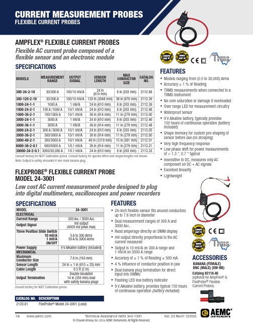
AMPFLEX ® FLEXIBLE CURRENT PROBESFlexible AC current probe composed of a flexible sensor and an electronic module FLEXPROBE ® FLEXIBLE CURRENT PROBE MODEL 24-3001Low cost AC current measurement probe designed to plug into digital multimeters, oscilloscopes and power recorders FEATURES• Models ranging from (0.5 to 30,000) Arms • Accuracy ± 1 % of Reading• TRMS measurements when connected to a TRMS instrument• No core saturation or damage if o verloaded • Over range LED for measurement c ircuitry • Waterproof sensor• 9 V Alkaline battery, typically provides 150 hours of continuous operation (battery included)• Shape memory for custom pre-shaping of sensor before use (no drooping)• Very high frequency response • Low phase shift for power m easurements of < 1.3 °, 0.7 ° typical• Insensitive to DC, measures only AC component on DC + AC signals • Excellent linearity • LightweightNote: Output is safety shrouded 4 mm male banana plug.Consult factory for NIST Calibration pricesFEATURES• 24-inch flexible sensor fits around conductors up to 7.6 inch in diameter• Dual measurement ranges of 300 A and 3000 A ac .• Read amperage d irectly on DMM d isplay • mV output directly p roportional to the AC current measured• Output is 10 mV/A on 300 A range and 1 mV/A on 3000 A range• Accuracy of ± 1 % of Reading ± 500 mA • 4 % influence of c onductor position in jaw • Dual banana plug t ermination for direct input into DMMs• Flashing LED low battery i ndicator• 9 V Alkaline battery, provides typical 150 hours of continuous operation (battery included)ACCESSORIESBANANA (FEMALE) BNC (MALE) (XM-BB) Catalog #2118.46(optional for AmpFlex ® & FlexProbe ® Flexible Current Probes)CATALOG NO.DESCRIPTION ®CURRENT MEASUREMENT PROBES GENERAL PURPOSE PROBES SELECTION CHARTCURRENT MEASUREMENT PROBES GENERAL PURPOSE PROBES SELECTION CHARTOSCILLOSCOPE & BNC TERMINATED PROBESNote: Consult factory for NIST Calibration priceMN261MN251TMN379TMH60MR417MR527*Phase shift indicated at maximum rating. Note: All probes are rated 600 V CAT III and CE compliant. Not all models are UL approved; please consult factory. Consult factory for NIST Calibration price.。
EP300系列产品使用说明书 ver 1.22-2
PON光功率计使用说明书Ver 1.22天津市德力电子仪器有限公司地址: 天津市高新技术产业园区(环外)海泰创新三路8号(300392)服务电话:022 2763 1088传真:022 2764 5002网址:电子邮件:deviser@保修仪器售出后保修3年,3年保修期到期之前,可以购买延长保修期服务。
用户的职责是:按照说明书来使用这台仪器,假如要维修,就把它送往本公司或指定代理维修站。
一般说来于保修期内,一切非人为使用不当的故障,当由德力公司免费维修。
用户需支付将产品退回至维修部门的运费和保险费,而将维修好的产品交付给用户的费用则由德力公司或指定代理维修站支付。
本公司为本产品设计的软件和硬件正确安装到仪器上后,仪器将执行它的编程指令。
但本公司不保证仪器的各种操作不间断或不出现错误信息。
保修只限于仪器,并不涉及使用不当而导致其它设备、生命及财产的损失。
保修限制保修不包括以下各项:①对因使用不当或有害清洁造成光探测器或光接口损坏而进行的更换,需要进行收费。
②随机赠送的电池或电源适配器。
③由于机械外力(撞击、跌落等)造成面板、开关、装置及机壳的变形损坏并涉及到内部器件的故障。
④擅自拆开仪器试图修理的。
⑤用户提货时,应当场查验,如遇仪器损毁,请向货运公司或部门交涉。
只有收货人(接收仪器的个人与单位)才有权就运输损毁向承运者提出赔偿要求。
开箱请小心开箱,并注意将全部附件放在一个地方,以防遗失。
我们建议最好保存原包装箱和包装材料,以备将来搬运时使用。
注意只有经过维修培训的人员才能维护本仪器。
为了避免损坏,未经过培训人员不应进行仪器的维护修理。
本说明书仅对随机产品有效,其中所载技术规格和操作方法可能改变,恕不另行通告。
使用一段时间后,如有何需要,请向生产商查询。
仪器断电后,内部电容仍可能带有电荷。
本公司保留所有版权,未经书面同意不得复制、改编或翻译。
目录一、安全性 (1)二、一般性说明 ................... 错误!未定义书签。
EP3001评估板手册说明书
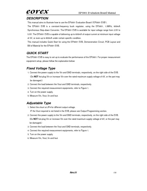
1/4DESCRIPTIONThis manual aims to illustrate how to use the EP3001 Evaluation Board (“EP3001 EVB”).The EP3001 EVB is a constant-frequency buck regulator, using the EP3001, 1.5MHz, 600mA Synchronous Step-down Converter. The EP3001 EVB is available for input voltage range from 2.5V to 5.5V. The EP3001 EVB is capable of delivering up to 600mA of output current at minimum input voltage of 3V, or even up to 800mA under certain specific condition.This manual includes Quick Start for using the EP3001 EVB, Demonstration Circuit, PCB Layout and Bill of Material for the EP3001 EVB.QUICK STARTThe EP3001 EVB is easy to set up to evaluate the performance of the EP3001. For proper measurement equipment setup, please follow the explanation below:Fixed Voltage Type1. Connect the power supply to the Vin and GND terminals, respectively, on the right side of the EVB. (Do NOT hot-plug Vin or increase Vin over the rated maximum supply voltage of 6V, or the part may be damaged.)2. Connect the load between the Vout and GND terminals, respectively.3. Connect the required measurement equipments, refer to Figure 1.4. Turn on the power supply.5. Measure Vin, Vout, Iin and Iout.Adjustable Type1. Select the shunt at JP4 for different output voltage.IF the Vout required is not listed in the EVB, please see Output Programming section. 2. Connect the power supply to the Vin and GND terminals, respectively, on the right side of the EVB. (Do NOT hot-plug Vin or increase Vin over the rated maximum supply voltage of 6V, or the part may be damaged.)3. Connect the load between the Vout and GND terminals, respectively.4. Connect the required measurement equipments, refer to Figure 1.5. Turn on the power supply.6. Measure Vin, Vout, Iin and Iout.2/4Jump Setting1. Default setting of JP1 is RUN, so as to enable the EP3001. If Shutdown condition is required, please turn off the power supply and switch JP1 to SHDN. Then power on to test the Shutdown condition. Do NOT keep JP1 floating at any time.2. JP3 is for voltage option only. FIXED is for fixed voltage option with the marking of “A2YW”, “A3YW”, “A4YW” and “C4YW”. ADJ is for adjustable voltage option with the marking of “A1YW”. Do NOT change JP3 at any time.3. JP4 is for output voltage selection for adjustable type. When AUX is selected, please see the following section.Output ProgrammingThe output programming resistors for adjustable type are listed in Table 1. If AUX with JP4 is selected, please put on R2F according to the following equation:+=1216.0R R V V out Table 1 Output Programming ResistorVout (V) R1 (K Ω) R2 (K Ω) 1.2 60 R2A = 60 1.5 60 R2B =90 1.8 60 R2C = 120 2.5 60 R2D =190 3.1 60 R2=250 3.3 60 R2E = 270 AUX60 R2F = FunctionFigure 1 EP3001 Evaluation Board Diagram3/4DEMONSTRATION CIRCUIT4/4BILL OF MATERIALItem Qty Ref. Part Description Manufacture/Part No.Note 11 C1CAP.,X5R Ceramic, 4.7uF,6.3V,20%,0805 MURATA,GRM31CR71A475KA01L2 1 C2CAP.,X5R,10Uf,6.3V,20%,1206 MURATA,GRM31CR70J106KA01L3 1 C3 CAP.,NPO, 22Pf,25V,20%,0603 GARRETT,0603CG220J9B204 1 L1 INDUCTOR,2.2uH,20% MURATA,LQH43CN2R2M03L 51 R1RES.,CHIP,60K,1/16W, 1%,0603AAC 6 1 R2ARES.,CHIP,60K,1/16W, 1%,0603AAC7 1 R2BRES.,CHIP,90K,1/16W, 5%,0603AAC8 1 R2CRES.,CHIP,120K,1/16W, 5%,0603AAC9 1 R2DRES.,CHIP,250K,1/16W, 5%,0603AAC10 1 R2ERES.,CHIP,270K,1/16W, 5%,0603AAC11 1U1IC,EP3001,SOT23-5A1YW, A2YW, A3YW, A4YW, C4YW。
Anton Paar SVM 3001 液体可视测量仪产品说明书
SVM™ Enables You to Certify Your Fuels for Both KinematicViscosity and Density in One GoRelevant for: producers (QC), fuel research, fuel wholesale traders, bulk consumers (e.g. vehicle fleet managers for incoming QC)The Anton Paar SVM™ 3001 allows for reliable determination of both kinematic and dynamicviscosity at all temperatures, which are relevant for diesel fuel. Get precision equal toASTM D445 with significantly less effort for cooling.1IntroductionBesides a number of other parameters, most diesel fuel types must fulfill viscosity specifications according to the respective standards. The SVM™ 3001 Stabinger Viscometer™ provides simultaneous determination of kinematic viscosity and densityaccording to ASTM D7042 (also DIN EN 16896) and D4052. It is an excellent solution for fast andeconomical viscosity measurement at standard as well as negative temperatures. Even for measuring the quality of winter diesel at -20 °C, no external cooling is required.This report describes specifically how to test diesel fuels with the SVM™ 3001 to get data comparable to ASTM D445, DIN 51562, and ISO 3104.2 InstrumentationFor testing diesel fuel at 40 °C, SVM™ 3001 does not need any additional accessories. For measurement at low temperatures, a supply of dry air is required. See chapter 2.1, "Accessories".For the -20 °C measurement of winter (arctic or polar) diesel, no external counter cooling is required. The instrument uses air cooling by an internal fan.2.1Accessories ▪ Glass syringe 5 mL2.1.1Drying facilities▪ Air preparation set dew point -40 °C or▪ Technical nitrogen and an appropriate pressure regulator to limit the maximum pressure to 1 bar The air preparation set allows the filling and cleaning at measuring temperature. Further, it keeps the interior of the instrument permanently dry.Figure 2: Air preparation set dew point -40 °C2.2 Installation For installing an SVM™ 3001 respectively the airpreparation set or a source of technical nitrogen, refer to the SVM™ 3001 Reference Guide.3 Measurement of diesel fuel 3.1Instrument preparationFor measurements in the standard temperature range, no special preparation is required. The cells should be clean, dry, and leak-tight. Perform regular checks and do preventive maintenance.For measurements at low temperatures, remove the measuring rotor. Purge the inside of the cell block for a few minutes with dry air to keep this tube dry. Insert the measuring rotor immediately afterwards and close the measuring cell lock. Now purge the measuring cell with dry air for a few minutes before cooling down to remove any traces of air humidity from the cells.3.2 SettingsFor measurements according to ASTM D7042▪ Method: Standard▪ Precision class: Precise ▪ RDV limit: 0.10 %▪ RDD limit: 0.0002 g/cm³ ▪ Automatic prewetting: yes ▪ Drying time:– built-in air pump, at 40 °C: 70 s– compressed dry air, 0.3 bar, at -20 °C: 60 sFor measurements according to ASTM D4052▪ Method: Standard▪ Precision class: Ultraprecise ▪ RDV limit: 0.10 %▪ RDD limit: 0.0001 g/cm³ ▪ Automatic prewetting: yes ▪ Drying time:– built-in air pump, at 40 °C: 80 s– compressed dry air, 0.3 bar, at -20 °C: 60 sAir preparation set – pressure▪ To prevent the cells from warming up too much when drying, 0.3 bar are sufficient.▪ Slow flow (few liters/min) to keep the interior of the instrument dry. Hose connected to the DRY AIR INTERNAL nozzle on the rear of SVM™ 3001.3.3 CalibrationBefore measuring the samples, perform a calibration. If required, apply a calibration correction to improve the reproducibility. Use a standard in the viscosity range of your diesel fuel samples. This can be a certified standard or a house-internal standard with kinematic viscosity values. In any case, you need reliable kinematic viscosity values at the measuring temperatures.To perform a calibration (correction), refer to the SVM™ 3001 Reference Guide.3.4 Sample preparationIf the sample is not freshly drawn from a production line or other reservoir, you can improve therepeatability by homogenizing the sample before taking the test specimen:▪ Fill approximately 100 mL of sample into a glass flask.▪ Close the flask and the original container immediately to avoid evaporation.▪ Stir the sample on a magnetic stirrer at low speed for approximately 5 minutes.3.5 FillingAlways use a glass syringe.The glass syringe supplied with the instrument has a Luer-Lock connector. Remove the filling hose from the measuring cell lock and attach an adapter Luer/UNF PEEK instead. Ensure that the measuring cells are leak tight, clean and dry.Fill at least 1.5 mL as first filling. After prewetting refill at least 1 mL or until the sample in the waste hose is free of bubbles. Sample volume: typically 5 mL3.6 Cooling times and sample throughput Sample throughput:▪ 40 °C: approx. 12 samples/hour ▪ -20 °C: approx. 8 samples/hourCooling times:Generally, the cooling time depends on the measuring temperature, and the ambient temperature,respectively, on the bath size and performance of the thermostat.When starting from room temperature and using air cooling, the SVM™ 3001 is ready for measurement at -20 °C after approximately 20 minutes.For better cooling performance or higher ambient temperatures (> 25 °C), use an external cooling circulator. Find suitable models in the SVM™ X001 Product Description List.3.7 Cleaning 3.7.1SolventsPetroleum benzine (hydrocarbon solvent, blend of mainly C7, C8, C9 n-alkanes) with a boiling range of 100 °C to 140 °C is a universal solvent for cleaning over a wide temperature range. Use this solvent as first solvent to remove the sample. To improve drying at low temperatures, use approximately 2 mL of n-heptane or n-hexane as second solvent.▪ Typical amount first solvent: 6 mL3.7.2Cleaning guidelinesThere is no special cleaning procedure required, as the sample is rather easy to remove. Consider the following hints:▪ Open the cleaning screen. Observe it during the cleaning procedure. It gives helpful information on the cleaning and drying status of the cells during the entire procedure.▪ Remove the sample from the cells by sucking it back into to syringe. This avoids leaking. ▪ For cleaning, a plastic syringe can be used. ▪ When using a single solvent, it must be volatile enough to dry up without leaving residues in the cells.▪ When using two solvents, perform a final flush with a drying solvent to remove any residues. ▪ Dry the measuring cells until the cleaning value turns green and stays steadily green. ▪For details, see the SVM™ X001 Instruction Manual or Reference Guide.4 ResultsThis report compares measurements of diesel fuel (DF-2) at 40 °C performed with SVM™ 3001(ASTM D7042) and with kinematic glass capillary viscometers (ASTM D445).Table 1: Comparison of ASTM D445 and D7042 results5References▪ ASTM D7042: Standard Test Method for Dynamic Viscosity and Density of Liquids by Stabinger Viscometer (and the Calculation of Kinematic Viscosity)▪ ASTM D4052: Standard Test Method for Density, Relative Density, and API Gravity of Liquids by Digital Density Meter▪ EN 16896: Petroleum products and relatedproducts - Determination of kinematic viscosity - Method by Stabinger Viscometer ▪ EN ISO 3104: Petroleum products -Transparent and opaque liquids - Determination of kinematic viscosity and calculation of dynamic viscosity▪ ASTM D445: Standard Test Method forKinematic Viscosity of Transparent and Opaque Liquids (and the Calculation of Dynamic Viscosity)▪ GOST 33-82 - Nefteprodukty. Metod opredeleniia kinematicheskoi i raschetdinamicheskoi viazkosti (Petroleum products. Method for determination of kinematic viscosity and calculation of dynamic viscosityContact Anton Paar GmbH Tel: +43 316 257-0**************************** APPENDIXAppendix A. About diesel fuelWhat is diesel fuel?Generally, diesel fuel is liquid fuel to power diesel engines used mainly in road vehicles, watercraft, rail vehicles, and stationary engines. It can be produced from different types of feedstocks.Petroleum dieselThis is a hydrocarbon mixture with approximately 8 to 21 carbon atoms per molecule. It is obtained by fractional distillation of crude oil under atmospheric pressure between 200 °C and 350 °C. Additionally, it contains additives. The most common grade is diesel fuel no. 2. An important parameter for the quality of a diesel fuel is the cetane number. The minimum cetane number is 51 according to EN 590. Typically, diesel fuels have a cetane number between 51 and 56. Higher cetane numbers are an indicator of better ignitability of the fuel when injected into the cylinder filled with hot compressed air. Viscosity is generally an important parameter for diesel fuel. Fuel, which is too highly viscous, can cause damage in the fuel pump (e.g. cam and follower wear) due to higher pressure. Too low viscosity may lead to a lack of lubrication. Viscosity also influences the fuel delivery rate and the atomization of the fuel during injection. BiodieselBiodiesel or FAME (fatty acid methyl ester) is an alternative diesel fuel derived from renewable feedstocks such as used cooking oils, rapeseed oil, animal fat, or soybean oil. It is obtained by transesterification. Pure biodiesel is known as B100. Mixtures of biodiesel with petroleum diesel are tagged as BXX, where XX is the percentage of biodiesel in the blend. The advantages of biodiesel compared to petroleum diesel are reduction of most exhaust emissions, improved biodegradability and a higher flash point.By the way – petroleum diesel also contains up to 7 % biodiesel according to country-specific laws.For transesterification, the oils or fats are mixed with methanol or ethanol and other additives. The ester linkages of these oils or fats (triglycerides, esters of free fatty acids) are cracked at normal pressure at approximately 60 °C. Then the fatty acids are transesterificated with the methanol or ethanol. The glycerin formed in this process is separated from the biodiesel. The transesterification process decreases biodiesel viscosity significantly compared to the basic material. The cetane number (a measure for the ignition performance) is increased. Synthetic dieselSynthetic diesel is not the same as biodiesel. It can be produced from any feedstock which contains carbon. This can be biomass, bio gas, natural gas or coal. The raw material is gasified into synthesis gas. After purification, this gas is converted into synthetic diesel fuel by variants of the Fischer-Tropsch process (originally, the Fischer-Tropsch synthesis was developed in the 1920s to produce fuel from coal). Depending on the feedstock, different types of production processes are known: biomass-to-liquid (BTL), gas-to-liquid (GTL), or coal-to-liquid (CTL), respectively. The most common variant is GTL. When using coal as feedstock, a disadvantage is a large release of greenhouse gases.Synthetic GTL diesel is free of sulfur, aromatics, nitrogen and others. It is not toxic and produces significant cleaner emission during combustion than diesel fuel refined from crude oil. Synthetic diesel has a high cetane number of 60, GTL diesel of 75 to 80. These fuels can be used in the same regions where diesel fuel is used, even in arctic zones.Winter dieselIn cold areas, diesel fuel tends to form solid wax particles, which thicken the fuel, clog fuel filters and injectors. Winter diesel uses special additives to lower the cold filter plugging point (CFPP, temperature at which wax particles form). The additives do not prevent the formation of wax particles, but they prevent the formation of large wax flakes. This means that the fuel stays liquid at lower temperatures. Basis for winter diesel can be petroleum diesel, a mixture of petroleum and biodiesel, or synthetic diesel. Depending on the area where it is used, one can distinguish between two types, winter diesel and arctic (polar) diesel.Diesel for cold climate zones is defined via the CFPP. EN 590 additionally states a viscosity limit at -20 °C. Appendix B. Why measure viscosity?Influence of viscosityViscosity is an essential parameter for the correct function of a diesel engine, as it directly influences the operation of the fuel injection system and of the fuel pump. The viscosity of biodiesel influences the lubrication of injection nozzle and injection pump, further the atomization of the fuel.Accurate monitoring of viscosity can serve to evaluate the quality of diesel fuels.Fuel injectionUnder high pressure, diesel fuel is injected directly or indirectly into the combustion chamber of a diesel engine via nozzles. The injection system produces a fine spray of fuel droplets, which evaporate rapidly when mixed with the hot compressed air in the cylinder. Droplet size and spray pattern are directly influenced by the fuel viscosity.If the viscosity is too high, the fuel droplets are not fine enough, which causes a worse combustion, more smoke and higher emissions. Too low viscosity can cause hot start problems or injector leakage.Fuel pump – performance and lubricationA too low viscosity can lead to a lack of lubrication of the fuel pump and consequently to increased wear or a failure. Too high viscosity at low temperatures will lead to problems in fuel conveyance – the higher the viscosity, the harder the pump must work to provide a constant fuel flow rate – and damages of the fuel injection pump (e.g. a seizure).Blending of diesel with biodieselFigure 3: Viscosity depending on biodieselconcentration, shows a summary result at 40 °C for diesel fuels with different contents of biodiesel. The viscosity of the product increases with increasing percentage of biodiesel.Figure 3: Viscosity depending on biodiesel concentrationThe viscosity curves follow a trend of power law according to the following equation (here shown for kinematic viscosity only): Equation 1:y = 2.3559 e 0.0059xy ... kinematic viscosityx ... % percentage by weight biodiesel in diesel fuelThis equation yields the calculation in the below table:Table 2: Viscosity calculation from equation 1This table shows, that if the percentage of biodiesel in diesel fuel does not exceed 5 %, both the limits of ASTM D975 can be met (see Table 3) and theenvironmental quality can be improved by adding 1 to 5 % of biodiesel without negative effects on efficiency and function of the engine.Viscosity parameters and typical viscosities The viscosity parameter for diesel fuels is kinematic viscosity. Depending on grade and usage, it is measured at +40 °C, further for winter qualitiesat -20 °C. The relevant specifications are stated in the respective standards and regulations.Table 3: Diesel fuel types – viscosity specifications* The viscosity limits of the ready blend product of biodiesel with petroleum diesel must not exceed the values given in ASTM D975. ** Maximum kinematic viscosity at -20 °C if the CFPP (cold filter plugging point) is -20 °C or lower. This applies to the CFPP classes F and 0 to 4 (see DIN EN 14214, EN 116/IP 309).Diesel fuel specification standards ▪ ASTM D975: Standard Specification for Diesel Fuel Oils▪DIN EN 14214: Automotive fuels. Fatty acid methyl esters (FAME) for diesel engines - Requirements and test methods▪ASTM D6751: Standard Specification forBiodiesel Fuel (B100) Blend Stock for Distillate Fuels▪ EN 116 / IP 309 Determination of CFPP▪MIL-DTL-16884M: Detail Specification of Fuel, Naval Distillate, F-75/F-76▪ GOST R 52368: Diesel Fuel Euro Specifications ▪ JIS K 2204: Diesel FuelLow temperature measurement – comparison to conventional viscosity measurementFor low temperature applications (-20 °C), there are generally two types of instruments available. Either large viscometer baths for simultaneously testing two or four capillaries, or compact desktop mini viscometers with 10-fold range capillaries. All these low temperature capillary viscometersrequire cooling liquids that stay clear at temperatures even lower than the measuring temperature. Such liquids usually are difficult to handle. They are either expensive (silicone oils) or have a low flash point (methanol) and involve a safety risk. On the contrary, even for testing at -40 °C, the counter cooling liquid for SVM™ 3001 is operated only at -5 °C, which permits the use of a low-price water/glycol mixture. Nor can these glass capillary viscometers perform cleaning and drying at the low measuringtemperatures – condensation is in the way. One automatic mini viscometer solves this problem by heating the apparatus for the cleaning procedure. However fast this is done, it still consumes more time and energy than the SVM™ 3001 with the air drying equipment.The following tables give an overview of the main differences between SVM™ 3001 and low temperature glass capillary viscometers:Table 4: Compare SVM™ 3001 to other viscometer baths。
福禄克 v3000 FC v3001 FC 安全须知 说明书
v3000 FCWireless AC Voltagev3001 FCWireless DC Voltage安全须知访问以注册您的产品并获取更多信息。
警告表示可能对用户造成危险的状况和操作。
警告为了防止可能发生的触电、火灾或人身伤害:∙仔细阅读所有说明。
∙请仅将产品用于指定用途,否则可能减弱产品提供的防护。
∙应按照指定的测量类别、电压或电流额定值使用。
∙请勿触摸大于 30 伏交流均方根、42 伏交流峰值或 60 伏的直流电压。
∙请勿在爆炸性气体、蒸汽周围或在潮湿环境中使用产品。
∙如有损坏,请不要使用产品。
∙如产品工作异常,请勿使用。
∙操作本产品前请确保电池盖关闭且锁定。
∙当显示电池电量不足指示时请更换电池,以防测量不正确。
∙请由经过认可的技术人员维修产品。
∙仅使用指定的备件。
∙请勿超出产品、探针或附件中额定值最低的单个元件的测量类别 (CAT) 额定值。
∙测量一个已知电压,以确定产品操作是否正常。
∙不要单独工作。
∙遵守当地和国家的安全规范。
穿戴个人防护用品(经认可的橡胶手套、面具和阻燃衣物等),以防危险带电导体外露时遭受电击和电弧而受伤。
PN 4466537 May 2014 (Simplified Chinese)© 2014 Fluke Corporation. All rights reserved.∙使用产品前先检查外壳。
检查是否存在裂纹或塑胶件缺损。
请仔细检查端子附近的绝缘体。
∙只能使用正确的测量类别 (CAT)、电压和电流额定探针、测试线以及转接器进行测量。
∙请勿使用已损坏的测试导线。
检查测试导线绝缘层是否损坏,是否有外露金属或有磨损迹象。
检查测试导线的通断性。
∙请将手指握在探头护指装置的后面。
∙测量时,请先连接零线或地线,再连接火线;断开时,请先切断火线,再断开零线和地线。
∙清洁产品前先移除输入信号。
∙取下护盖或打开机壳时,请勿操作产品。
这样做可能会接触到危险电压。
为确保安全运行和维护产品:∙如果长期不用仪器,请将电池取出,以防电池泄漏而损坏仪器。
TE3001 电气火灾监控设备 安装使用说明书
TE3001电气火灾监控设备安装使用说明书(Ver.1.0,2018.10)前言电气火灾监控系统是深圳市泰和安科技有限公司为适应工程设计需要而开发的一套系统。
电气火灾监控系统依据GB 50016-2014《建筑设计防火规范》、GB 50116-2013《火灾自动报警系统设计规范》、GB 25506-2010《消防控制室通用技术要求》、GB 14287.1-2014《电气火灾监控系统第1部分:电气火灾监控设备》标准要求而设计,为室内使用设备。
TE3001电气火灾监控设备采用壁挂式结构,模块式设计,具有功能强、可靠性高、配置灵活的特点。
系统采用128×64点汉字液晶显示,全汉字操作及提示界面。
打印机可打印系统所有报警、故障及各类操作的汉字信息。
最大容量为100个地址点,具有全面的现场编程能力。
本安装使用说明书应由专人负责,妥善保管,以备日后查用。
目录1 概述 (4)2 功能 (4)3 特点 (4)4 技术指标 (4)5 配置说明及结构特征 (5)5.1 外观及面板说明 (5)5.2 内部结构说明 (6)5.3外接端子说明 (7)5.4布线要求 (7)5.5接线说明 (7)6 安装与调式 (8)6.1 开箱检查 (8)6.2 监控设备内部配置及连接状况检查 (8)6.3 开机前检查 (8)6.4 安装方法 (8)6.5 外部设备检查 (9)6.6 调试 (9)7 操作说明 (9)7.1 键盘介绍 (9)7.2 键盘的解锁与锁键盘 (9)7.3进入主菜单 (10)7.4查询实时信息 (10)7.4.1报警信息查询 (10)7.4.2联动信息查询 (10)7.4.3故障信息查询 (11)7.4.4屏蔽信息查询 (11)7.5记录查询 (11)7.6登录查询 (11)7.6.1总线部件 (11)7.6.2回路登录信息 (12)7.6.3重新登录 (12)7.7屏蔽操作 (12)7.8用户操作 (13)7.8.1时间设置 (13)7.8.2打印设置 (13)7.8.3系统工作模式 (13)7.8.4密码设置 (13)7.8.5按键声设置 (14)7.8.6联动模式 (14)7.9管理员操作 (14)7.9.1分机网络设置 (14)7.9.2总线设备配置 (15)7.9.3离线设置 (16)7.9.4联动编程 (16)7.9.5恢复出厂设置 (16)7.10复位 (17)7.11查询 (17)7.12自检 (17)7.13 消音 (17)7.14 操作级别设置 (17)8 常见故障及维修 (17)9 日常维护及保修 (18)10 打印机使用说明 (18)请联系我们 (19)1 概述TE3001型电气火灾监控设备(简称监控设备)是根据国家标准GB14287.1-2014《电气火灾监控系统第1部分:电气火灾监控设备》,针对电气火灾进行实时监控的全新系统。
EBT3001以太网串口服务器芯片模块配置方式简介
EBT3001以太网芯片模块功能及配置方式简介EBT3001以太网芯片产品简介EBT3001以太网芯片是实现串口数据与以太网数据互相转换的串口芯片;该串口转以太网芯片具有多种Modbus网关模式以及MQTT/HTTP物联网网关模式,可满足各类串口设备/PLC 的联网功能。
EBT3001串口转以太网芯片功能特点支持多种工作模式(TCP Server、TCP Client、UDP Server、UDP Client);支持网页设置、配置工具设置、AT 指令设置参数;支持多路Socket 连接;支持多种校验(None、Odd、Even、Mark、Space);支持DHCP 功能;支持DNS 功能、域名解析;支持DNS 服务器地址自定义;支持多种Modbus 网关(简单协议转换、多主机模式、存储型网关、可配置型网关);支持快速接入阿里云、百度云、OneNET、华为云、3.1 版本标准MQTT 服务器;支持HTTP 协议(GET/POST 请求);支持虚拟串口;支持超时重启功能,重启时间自定义;支持短连接功能,短连接间隔时间自定义;支持心跳包、注册包功能;支持缓存清理功能;支持访问外网、局域网;独立设计测试套件,方便用户调试使用;支持在线升级功能。
EBT3001串口转以太网芯片Web设置配置可通过Web 设置方式,自定义设置相关参数。
打开浏览器,在地址栏输入设备IP(默认:192.168.3.7),进入页面,可查询、设置参数,最后点击“提交”菜单等待网页返回成功提示,即可生效。
注意:请勿在正常使用中进入网页配置,可能导致数据丢失,若进入网页配置则需要通过重启才能进入通讯模式。
网页配置初始化密码:123456,可自定义配置,仅支持6 位大小写字母与数值配置。
网页配置需要使用较新内核的浏览器才能正常使用,比如Microsoft Edge(96.0.1054.62)、Google chrome(96.0.4664.110)、Firefox(95.0.2)等。
- 1、下载文档前请自行甄别文档内容的完整性,平台不提供额外的编辑、内容补充、找答案等附加服务。
- 2、"仅部分预览"的文档,不可在线预览部分如存在完整性等问题,可反馈申请退款(可完整预览的文档不适用该条件!)。
- 3、如文档侵犯您的权益,请联系客服反馈,我们会尽快为您处理(人工客服工作时间:9:00-18:30)。
Edi-Tensor EPT3001
建议应用设计说明
Version:1
Date:2009/04/17
内容
一. EPT3001基本说明
1)外观说明
2)包装说明
二. EPT3001设计原理
1)动作原理
2)电源控制
3)电路设计
4)输出电位
5)旋转角度
6)layout设计
三. EPT3001建议应用功能
1)影像旋转或前后页相片选择
2)桌布更换
3)歌曲切换
4)静音开关
5)闹钟开关
6)简易游戏
四. 建议进阶功能
1)[确认]/[上卷页]/[下卷页] 按钮功能
一. EPT3001基本说明
1)外观说明
2)包装说明
二. EPT3001设计原理
1)动作原理
2)电源控制
1. 电源操作电压: 3.3V 、
2.8V
2. 建议与手机屏幕开关连动, 屏幕开启时此组件才开始动作, 可 避免误动作及达到省电效果。
3)电路设计
Operating voltage
(volt)
Input Current
(mA)
R1 (ohm) R2 (ohm) R3 (ohm)
3.3 3 630 33k 33k 2.8
3
470 33k 33k
[注] E1, E2只能接入GPIO pin; 无法直接接入[I 2C]
4)输出电位
[注] E1, E2讯号输出为连续不间断的,读取可藉由IC 程序设计,在 需求时才读取, 也可以一直读取, 依应用功能而定。
5)旋转角度
说明:
1.组件相对于空间Z 轴倾斜30°以内,可以正常作动。
2.组件旋转角度超过75°,输出讯号会进行切换。
例如旋转角度θ = 0° →
75°,讯号输出01 → 00。
6)layout设计
1.pad layout建议
2.组件layout位置建议位于屏幕中央或上方。
组件摆放方向建议为
辨识白点朝右下方。
三. EPT3001建议应用功能设计
1) 影像旋转或前后页相片选择
使用方式: 旋转或摇动
使用时机: 屏幕旋转或换相片
1-1影像旋转
1-1-1 影像向左旋转
0秒1秒2秒3秒4秒
時間軸
1-1-2 影像向右旋转
0秒1秒2秒3秒4秒
時間軸
1-2影像切换
1-2-1 相片后翻页– 换相片
0秒1秒2秒3秒4秒
時間軸
1-2-2 相片前翻页– 换相片
0秒1秒2秒3秒4秒
時間軸
2) 桌布更换
在桌布功能下, 设定方式如1)项[影像旋转或前后页相片选择]
3) 歌曲切换:
在歌曲模式, 设定方式如1)项[影像旋转或前后页相片选择]
4) 静音开关
使用方式: 翻转
使用时机: 来电时
0秒1秒2秒3秒4秒
時間軸
直接由(0,0)状况, 翻转至(1,1)状况, 停留1秒后, 再翻转回(0,0)状况, 做为功能开关; 第一次操作功能开启, 第二次操作功能关闭
注: 停留时间可在1~3秒(依设计需求自行调整)
5) 闹钟开关
使用方式: 摇动或旋转或翻转
使用时机: 当闹钟功能启动时
无论在那一种状态, 只要闹钟启动, 持续摇动或旋转或翻转手机1秒后, 闹钟关闭
[注] 摇动时间可在1~5秒(依设计需求自行调整)
6) 简易游戏
使用方式: 旋转, 摇动
使用游戏:
1)掷骰子
2) 百变求签
3) 大富翁接钱币
4) 推啤酒
四. 建议进阶功能
1) [功能开关]模式 – 特别功能
0 秒1秒2秒
時間軸
直接由(0,0)状况, 翻转至(1,1)状况, 停留1秒后, 再翻转回(0,0)状况, 做为功能开关; 第一次操作功能开启, 第二次操作功能关闭
2) [确认]/[上卷页]/[下卷页] 按钮功能
进入功能选项后,
1-1[确认]模式操作:
0秒1秒2秒3秒4秒
時間軸
1-2[上卷页]模式操作 – 右转
0秒1秒2秒3秒4秒
時間軸
可设定停留时间1~2秒后, 每0.5秒移动一个选项; 回复(0,0)时表示停止[上卷页]
1-3[下卷页]模式操作 – 左转
0秒1秒2秒3秒4秒
時間軸
可设定停留时间1~2秒后, 每0.5秒移动一个选项; 回复(0,0)时表示停止[下卷页]。