外文文献及翻译_CONTROL OF AN AXIAL PISTON PUMP USING A SINGLE-STAGE ELECTROHYDRAULIC SERVOVALVE
中英文文献翻译-混凝土泵车液压系统的认识
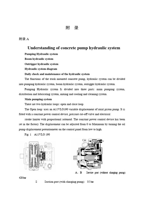
附录附录AUnderstanding of concrete pump hydraulic systemPumping Hydraulic systemBoom hydraulic systemOutrigger hydraulic systemHydraulic system diagramDaily check and maintenance of the hydraulic systemThe functions of the truck mounted concrete pump, hydraulic system can be divided into pumping hydraulic system, boom hydraulic system, outrigger hydraulic system.Pumping Hydraulic system Is divided into three parts: main pumping system, distribution and lubricating system, mixing and cooling and cleaning system.Main pumping systemThere are two hydraulic loops: open and close loop.The Open loop: uses an A11VLO190 variable displacement of axial piston pump. It is fitted with a constant power control device, pressure cut-off valve and electrical stroke limiter with proportional solenoid. The constant power control device has beenset in the factory. The displacement can be adjusted from 0 to Maximum by turning the oil pump displacement potentiometer on the control panel from low to high.Fig. 1 A11VLO 190A,B Service port (without charging pump) 420 barS Suction port (with charging pump) 35 barT1, T2 Air bleed, tankR Air bleed, oil drainM1 Measuring point, regulating chamberM Measuring point, service portG Port for positioning pressure (controller) for version with stroke limiter (H.., U2), HD and EP with screwed fitting GE10 – PLM (otherwise port G closed)The other is the control line, which can change the flow direction and the displacement of main pump through constant power valve, proportional solenoid pressure reducing valve, directional control valve and servo valve of main pump.The Closed loop: There is an auxiliary pump with relief valve that the setting pressure is 3.5Mpa in A4VG180. The auxiliary pump has two output ways. One is the charge oil line, which connects with suction line of main pump through the check valve in two pressure relief valves and add oil to main pump. At the same time excessive hydraulic oil return to oil tank through flushing valve and cooler to realize heat exchange for closed loop.A, B Service line ports SAE 1 1/4", high pressure series 420 barT1 Case drain or filling portT2 Case drain M33×2; 18 deepM A, M B Pressure gauge - operating pressure A, BR Air bleedS Boost suction portX1, X2Control pressure ports (before the orifice)G Pressure port for auxiliary circuitP S Control pressure supplyFa Filter outletFa1Filter outlet (filter assembly)Fe Filter inlet M33×2; 18 deepF S Port from filter to suction line (cold start)M H Port for balanced high pressureY1, Y2Remote control ports (only for HD control)Flushing valveUsed for closed loop to prevent excessive heat build-up in closed circuit operation. The setting pressure of flushing valve is 3.0MPaPressure reducing valve with proportional solenoidUsed for closed loop. The Output pressure is connected with the remote control port of main pump to control the displacement and is controlled by a proportional current signal and constant power valve. The displacement can be adjusted from 0 to Maximum by turning the displacement adjusting potentiometer.Constant power valveUsed for closed loop. When the hydraulic system pressure is over the setting pressure, the valve works to reduce the output pressure of the pressure reducing valve and maintain the constant power.Fig.3 Constant power valveMain pump suction filterOpen loop: filtration fineness 100u.Close loop: filtration fineness 20u.When the indicator in the vacuum gauge exceeds the safe area or the electric signal instrument gives a warning, the cartridge may be blocked. It should be clean or replace filter cartridge promptly.Filter filtration fineness is 20u in open loop. When the reading pressure of the vacuum gauge exceeds 0.35Mpa, the cartridge may be blocked. It should be clean or Return filterreplace filter cartridge promptly.Filter filtration fineness is 10u in closed loop. When the electricity deliver reports to the police, the cartridge may be blocked, it should be clean or replace filter cartridge promptly.Distribution and lubricating systemConstant pressure pumpFig.4 Constant pressure pumpAn A10VO28 constant pump is used for the distribution system of supply oil.The setting of the pressure control valve of the pump is 16Mpa. Once the system pressure is reached, the bump will keep this pressure then decrease the displacement. Thereis a pressure relief valve in the distribution circuit to act as a safety valve, which is set to 18Mpa.Plate ball valve (shut-off valve)Used to discharge the accumulator. It must be rotated the lever of shut-off valve anti-clockwise when the pumping finishes or stopped for maintenance, in order to discharge the pressure of theaccumulator. (Pressure gauge of distribution system is zero) AccumulatorInflation pressure is 8-9Mpa. Use Only Nitrogen to fill the accumulator. Charging pressure should not exceed these figures.Lubricating systemThere are two types. One is reciprocating centralized lubrication that is driven by oil from the swing cylinders of distribution system includes lubricating single pump (or double pump), distributor, damper and filter. The other is automatic centralized lubrication that is driven by a D.C motor with an independent grease tank and independent from the hydraulic system. The interval time of lubrication is carried out in the factory. The lubrication system works automatically when pumping.Mixing, cooling, cleaning systemOnly the Mixing, cooling, cleaning system are driven by motor in open loop.Gear pumpGear pump supplies oil to the mixing, cooling, cleaning system.Sandwich type relief valveThe pressure is set to 14Mpa.Ressure relayIf the mixing blade is stuck, the system pressure will raise. When the pressure exceeds the setting value (usually 10Mpa), the pressure relay will give a warning. The Solenoid directional control valve changes direction to let the mixing motor to rotate anti-clockwise. After 6 second the solenoid valve will reset, and the mixing motor will rotate clockwise again.Return filterThe filtration fineness is 10u in closed loop. The cartridge may be blocked when the electric alarm sounds. It should be replace promptly.Boom hydraulic systemBoom pumpBoom and outrigger use the same pump.37m and 40m truck mounted concrete pumps: A2FO23 fixed displacement pump44m and 47m truck mounted concrete pumps: A7VO55LRDS variable displacement pump, or A7VO55DRS variable displacement pump46m and 49m truck mounted concrete pumps: A7VO55LRDS variable displacement pumpFig.5 A7VO55DRS Fig.6 A7VO55LRDS Fig.7 A2FO23Boom proportional directional spool valveThe proportional directional spool valve with electro-hydraulic consists of pressure relief valve, pressure reducing valve, and flow control valve, and can becontrolled manual or by remote control.Fig.8 Boom proportional directional spool valveLoad-holding valveLoad-holding valve has thre e functions. (1) It acts as a lock when the cylinder isn’t moving. (2) Load-holding valve has twice relief function to protect boom against vibrating. It will be adjusted in the factory. (3) When the boom moves downward asSlewing load-holding valvegravity load, it can limit speed to prevent the boom falling too quickly and shaking.There are three main functions. Lock, overload protection and speed limiting.Outrigger hydraulic systemOutrigger hydraulic system and boom hydraulic system are used the same pump to supply oil. Outriggers should be set up before the boom is operated by the control levers or electric control button on both sides of the truck mounted concrete pump.Outrigger proportional directional spool valveIt is an integrated unit with a relief valve inside to control maximum pressure of theoutrigger hydraulic system.Fig .9 Outrigger proportional directional spool valveOutrigger hydraulic lockIt is used to lock the outrigger cylinders and pay attention to the vertical moving of the outrigger cylinder when working .Pressurerelief附录B混凝土泵车液压系统的认识泵送单元液压系统 臂架液压系统 支腿液压系统 液压原理图液压系统的日常保养及维护泵车液压系统按泵车功能可划分为泵送单元液压系统、臂架液压系统、支腿液压系统。
汽车变速器外文翻译

外文翻译Auto TransmissionFirst, an overview of automotive transmission and the development trendAutomobile available more than a century, especially from the mass production of motor vehicles and the automotive industry since the development of large, Car has been the economic development of the world for mankind to enter the modern life and have had a tremendous impact on the immeasurable, The progress of human society has made indelible contributions to the great, epoch-making set off arevolution. From From the vehicle as a power plant using internal combustion engine to start, auto transmission has become an important component. Is Generation is widely used in automotive reciprocating piston internal combustion engine with a small size, light weight, reliable operation and the use of The advantages of convenience, but its torque and speed range of smaller changes, and complex condition requires the use of motor vehicles Traction and the speed can be considerable changes in the scope. Therefore, its performance and vehicle dynamics and economy of There are large inter-contradictions, which contradictions of modern automotive internal combustion engine by itself is insoluble. Because Here, in the automotive power train set up the transmission and main reducer in order to achieve the purpose of deceleration by moment. Speed The main function of performance: ⑴ change gear ratio of motor vehicles, and expand the wheel drive torque and rotational speed of the Fan Wai, in order to adapt to constantly changing driving cycle, while the engine in the most favorable conditions within the scope of work; ⑵no change in the direction of engine rotation, under the premise of the realization of cars driving back; ⑶the realization of the free, temporary Interruption of power transmission, in order to be able to start the engine, idling, etc.. V ariable-speed drive transmission by the manipulation of institutions and agencies. Change the transmission ratio by way of transmission is divided into There are class-type, non-stage and multi-purpose three. Have class most widely used transmission. It uses gear drive, with a number of transmission ratio setting. Stepless transmission Continuously V ariable Transmission (CVT) transmission ratio of a certain The framework of multi-level changes may be unlimited, there is a common type of power and torque (dynamic fluid-type) and so on. Continuously V ariable Transmission Transmission development is the ultimate goal, because only it can make the most economical engine in working condition Can provide the best vehicle fuel economy and optimal power in order to provide the most comfortable By the feeling. Today's CVT is a typical representative of the CVTand IVT, however as a result of the reliability of Poor, non-durable materials and high cost issues, development is not very good. Comprehensive refers to transmission torque converter and the mechanical components have the level of transmission variable hydraulic mechanical Speed, the transmission ratio can be between the maximum and minimum range of a few discontinuous change for no class, but its Significantly lower transmission efficiency than the efficiency of gear drives. 2 By manipulation, transmission control type can be divided into mandatory, automatic and semi-automatic control to manipulate three - Species . Mandatory on the driver to manipulate the direct transmission gear shift control for the majority of motor vehicles used Also known as Manual Transmission Manual Transmission (MT). Automatic transmission control selection of the transmission ratio (transmission) is carried out automatically. Just add the driver to manipulate Speed pedal, you can control the speed, also known as Automatic Transmission Automatic Transmission (A T). It is According to the speed and load (throttle pedal travel) for two-parameter control, stall in accordance with the above two Parameters to automatically take-off and landing.A T and MT in common is that they are level transmission, but A T According to the speed of the speed shift automatically, you can eliminate the manual transmission "setback" of the shift feel. However, A T also have many drawbacks, such as body complex, mechanical efficiency is not high, high cost, reliability and control Sensitivity remains to be increasing . AMT (Automated Mechanical Transmission) is in the traditional dry clutch and manual transmission gear based on the transformation of form, mainly to change the part of the manual gearshift control. That is, the overall structure of the MT cases the same switch to electronically controlled automatic transmission to achieve. Semi-automatic control, there are two forms of transmission. A number of stalls is a common automatic control, and the remaining stalls manipulated by the driver; the other is pre-style, that is, pre-selected pilot stalls, the clutch pedal in the down or release the accelerator pedal, the for retirement or an electromagnetic device to shift the hydraulic device. In recent years, with advances in vehicle technology and road traffic density increased, the performance requirements of the transmission is also getting higher and higher. A large number of automotive engineers in improving the performance of automobile transmission study a great deal of effort devoted to the rapid transmission of technology development, such as A T, AMT, DCT, CVT and the emergence of IVT.2003 Hyundai A T, AMT, DCT, CVT forum reached a consensus on the following:in the next Development, MT will continue to be the most widely used automotive transmission, AMT will increase the proportion of the application, A T also Will occupy a large market share, CVT's use of certain limitations, can only be due to a number of small displacement Car, DCT (dual clutch transmission) will also be the budding growth. From 2003 to now, vehicle speed Thedevelopment of devices and the forum basically the consensus reached by consensus. By comparing the analysis, the traditional mechanical transmission is still the most widely used vehicle change Speed. Although it has many shortcomings, such as shifting the impact of large, bulky, cumbersome to manipulate and so on; however, it also There are many advantages, such as high transmission efficiency, reliable operation, long life, manufacturing processes mature and low cost. Therefore, if we can improve the mechanical transmission of the above-mentioned shortcomings, it still has great room for development.Second, Manual Transmission Fault DiagnosisManual transmission at the beginning of the fault diagnosis prior toFailure to confirm from other parts is not: to check the tire And wheels, to confirm the normal tire pressure, and the wheel is flat V alue of; to confirm instead of noise and vibration from the engine. Clutch , And steering and suspension, etc..(A), skip file1. PhenomenonV ehicle acceleration, deceleration, climbing or severe vehicle vibration, the gear lever neutral position automatically jump.2. Reasons① self-locking device of the ball did not enter the grooves or linked file does not meet the full-gear tooth meshing long;② self-locking device worn groove ball or serious, self-locking spring is too soft or broken fatigue;③ gear along the direction of tooth wear as a long cone-shaped;④ one or two too松旷shaft bearing, so that one or two three-axis and the crankshaft axis of the heart or different transmission and clutch shell shell bonding plane of the vertical axis the relative change in the crankshaft;⑤ Second Gear axis often axial or radial gap is too large;⑥ the axis of axial or radial gap is too large.3. Fault diagnosis and troubleshootingJump to file stalls Unascertained: After taking heat the entire vehicle, increase the use of continuous, slow approach to road test each file is determined.Will jump to the gear lever hanging file stalls the engine off, transmission cover removed carefully to observe the mating dance gear case file.① engagement does not meet the length, then the resulting fault;② to reach a total length of engagement, should continue to check;③ check mating wear parts: wear into a cone, then failure may be caused by;④ check b-axis of the gear profile and the axis of the axial and radial clearance, clearance is too large, then failure may be caused by;⑤ check self-locking devices, locking devices, if only a very small dynamic resistance, and even feel the ball is not plugged groove (the transmission cover caught in the vice, the hand-shaking shift stroke), the fault for the bad performance of self-locking ; Otherwise, the fault for the clutch and gearbox shell bonding plane and the vertical axis of the crankshaft caused by changes.(B), arbitrary files1. PhenomenonTechnical condition in the clutch normal circumstances, transmission at the same time put up or two files linked to the need to stall, the results linked to other stalls.2. Reasons① interlocking device failure: if the fork shaft, pin or interlocking interlocking ball too much wear and tear, etc.;② the bottom of the arc gear face wear and tear is too large or fork axis of the allocated blocks wear groove is too large;③ball pin gear lever broken or the ball-hole, ball松旷wear too. In short arbitrary file transmission is mainly due to institutional failure manipulation.3. Fault diagnosis and troubleshooting① linked to the need to stall, the results linked to the other stalls: rocking gear lever, to check their point of view before, if in excess of the normal range, while the lower end of failure by the gear lever ball pin and the positioning groove ball with or松旷, the ball is too large holes caused by wear and tear. Swung shift 360 °, compared with a broken pin.② If the pendulum angle to normal, still not on, or linked to more than picking file, then the lower end of failure by the gear lever away from the limitations arising from the groove in (due to break away from the bottom of the arc-shaped guide groove face wear and tear or wear).③ At the same time linked to the two files: the fault caused by the interlocking device failure.(C), the difficulties linked to files1. PhenomenonClutch technical condition, but can not be linked smoothly linked file into the stalls, often percussive sound gear.2. Reasons① synchronizer failure;② Bending fork shaft, locking the spring strong, ball injury, etc.;③ a shaft or a spline shaft bending injury;④ inadequate or excessive gear oil, gear oil does not meet the specifications.3. Fault diagnosis and troubleshooting①Synchronizer check whether the fall to pieces, cone ring is conical spiral groove wear, whether worn slider, spring is too soft, such as elastic.② If the Synchronizer normal, check whether the bending of a shaft, spline wear is severe.③ check whether the mobile axis normal fork.(D), abnormal sound transmission1. PhenomenonTransmission refers to transmission work abnormal sound when the sound is not normal.2. Reasons1) abnormal sound gearGear wear off very thin gap is too large, the impact of running in; bad tooth meshing, such as the repair did not replace the gear pairs. New and old gear with the gear mesh can not be correct; tooth metal fatigue spalling or damage to individual teeth broken; gear and the spline shaft with松旷, or the axial gear clearance is too large; axis caused by bending or bearing松旷space to change gears.2) Bearing ringSerious bearing wear; Bearing (outer) ring with the journal blocks (holes) with the loose; Ball Bearing Ma break-up or a point of ablation.3) ring made for other reasonsSuch as the transmission within缺油, lubricants have been thin, too thick or quality deterioration; transmission into the foreign body inside; some loose bolts fastening; odometer or the odometer shaft ring gear, such as fat.3. Troubleshooting①transmission issued metal dry friction sound, which is缺油and the poor quality of oil. Refueling and inspection should be the quality of oil, if necessary, replacement.② for moving into a file if the sound obvious, namely, the profile of gear tooth wear; If the occurrence of cyclical noise, while damage to individual teeth.③when the ring gap, and riding the clutch pedal under the noise disappeared after the general axis is a before and after the bearing or regular engagement ring gear; if any files are changed into the ring, after more than two-axis bearing ring.④transmission occurs when a sudden impact the work of sound, most of the tooth was broken and should be removed timely transmission inspection cover to prevent mechanicaldamage.⑤moving, only for transmission of a file into the ring gear made in the above-mentioned good premise, it should check with improper gear mesh, if necessary, should be re-assembling a pair of new gear. In addition, it may be synchronizer gear wear or damage should be repaired or replaced depending on the circumstances.⑥ when shifting gear ring made of impact, it may be the clutch or the clutch pedal can not be separated from stroke is incorrect, damaged synchronizer, excessive idling, gear improperly adjusted or tight-oriented, such as Bush. In such cases, to check whether the separation of the clutch, and then adjust the idle speed or the gear lever, respectively, the location, inspection-oriented with the bearing bushing and separation tightness.If excluded from the above examinations, the transmission is still made ring, should check the shaft bearings and shaft hole with the situation, bearing the state of their own technology, etc.; as well, and then view the odometer shaft and ring gear is made and, if necessary, be repaired or replacement.(E), transmission oil1. PhenomenonAround the transmission gear lubricants, transmission gear box to reduce the fuel can be judged as lubricant leakage.2. Reasons and troubleshooting① improper oil selection, resulting in excessive foam, or the volume too much oil, when in need of replacement or adjust the lubricant oil;② side cover is too loose, damaged gaskets, oil seal damage, damage to seals and oil seals should be replaced with new items;③ release and transmission oil tank and side cover fixed bolts loosening, tightening torque should be required;④ broken gear-housing shell or extended wear and tear caused by oil spills, must be replaced;⑤ odometer broken loose gear limit device must be locked or replaced; gear oil seal oil seal oil should be replaced.Third, the maintenance manual gearboxSantana is now as an example:Santana used to manually synchronize the entire, multi-stage gear transmission, there are four forward one block and reverse gear. Block are forward-lock synchronizer ring inertial, body-wide shift synchronizer nested engagement with a reasonable structure, the layout of a compact, reliable, long life and so on. However, if the use and maintenance is not the right way to do so, failure mayoccur at any time.The proper use of Synchronizer:1, the use of addition and subtraction block off both feet. Block addition and subtraction, if the clutch with one foot, then the speed at the time of addition and subtraction block must be correct, the timing should be appropriate and, if necessary, to addition and subtraction can be blocked off both feet, so that addition and subtraction method can reduce the block with Gear speed difference between the circumference, thereby reducing wear and tear Synchronizer to extend the life of Synchronizer.2, prohibited the use of tap-shift gear lever when the method (that is, a push of the operation of a song). Hand should always hold down the shift, this can greatly reduce the synchronizer sliding lock Moreton Central time and reduce wear and tear.3, no state in the gap off the use of force挂挡synchronizer start the engine. Moment of inertia as a great engine, the friction torque Synchronizer also small, so the time synchronization process is very long, so that lock ring temperature increased sharply, it is easy to burn synchronizer.4, is strictly prohibited by synchronizer clutch instead of the initial (that is, the use of non-use of the clutch friction synchronizer start挂挡role), control speed and braking.The correct use of lubricants:Santana at the factory, the transmission has been added to the quality of lubricating oil, under normal circumstances, the level of the transmission lubrication need to be checked. However, when normal travel 100,000 kilometers 10,000 kilometers -20 after the first lubricating oil must be replaced. Santana grade lubricants used in transmission as follows: Gear Oil API-GLA (MIL-L2105), SAE80 or SAE80W-90 grade汽车变速器一、汽车变速器概述及发展趋势汽车问世百余年来,特别是从汽车的大批量生产及汽车工业的大发展以来,汽车己为世界经济的发展、为人类进入现代生活,产生了无法估量的巨大影响,为人类社会的进步作出了不可磨灭的巨大贡献,掀起了一场划时代的革命。
Rotary Power Axial Piston Pumps和Cam Motors商品说明书

ROTARY POWER has over35years experience in the design and development of high quality Hydraulic equipment.Our current product range includes:-"A"Axial Piston Pumps for heavy-duty open circuit applications.Wide range of controls.Excellent life characteristics.Suitable for most fluids,including HLP,HFA,HFB,HFC,HFD,HFR,HFE,Isocyanates&Polyols.Fixed and variable capacities from11.5to125cm3/rev."C"Axial Piston Pumps for high accuracy fluid metering with precision flow controls and high-pressure capability.Specifically designed for the Polyurethane Industry.Capacities from2to125cm3/rev."XL"Cam Motors of radial piston configuration.Wheel/shaft/torque module configurations.Design offers high-speed capability.Capacities from150to 1120cm3/rev."X K"C a m M o t o r s r a d i a l p i s t o n c o n f i g u r a t i o n o f f e r i n g static/dynamic brakes,single/2speed,wheel/shaft&torque-module mount options.Heavy-Duty External Load&High-Speed options.Capacities from1000to5000cm3/rev."SMA"Motors heavy-duty radial piston/eccentric configuration,offering excellent life.Withstands high mechanical and hydraulic shock loads.350bar Continuous pressure rating.Speed&power ratings significantly greater than standard HTLS motors.Displacements from200to16,400cm3/rev.Wholly owned subsidiaries in the USA and Germany and a network of distributors throughout the world provide product support in most countries.ROTARY POWER is a company within British Engines Ltd(BEL)group, which was established over60years ago.The British Engines group of companies design manufacture and market a wide range of engineered products for offshore,electrical, construction,engineering and other industries,employing nearly700 people on a4600sq m site in Newcastle upon Tyne,England.SMA FEATURESI Most SMA motors are designed for continuous350bar&intermittent 490bar duty.I Will withstand higher peak pressures.I Designed for continuous high power use.I Designed to operate over a wide speed range.I Up to150:1for standard models.I Up to1000:1for some special models.I Minimal no load pressure drop even at high speed.I Efficient design based on hydrostatic &taper roller bearings.I Built to withstand high mechanical& hydraulic shock load.I Hardened high tensile steel crankshaft supported in large taper roller bearings.I Gears may be mounted directly on motor shafts(please ask for details).I Max system pressure allowed on inlet and outlet ports simultaneously.I This allows greater system flexibility.I True freewheel possible.I Recirculating freewheel possible.I Displacement ratios range1.6-2.6 I for multi-motor circuits,series/parallel circuits are possible.I Typically60%higher rating than standard SMA motors.I Suitable for use with most hydraulic fluids.I HFA,HFB,HFC,HFD.High EfficienciesFluid VersatilityHigh Power Options Multi Displacements FreewheelSeries Operation RobustHigh Power Capability High Speed RangeHigh Pressure CapabilityS M A R A D I A L P I S T O N M O T O R SOPERATIONSELECTIONCODESDATA-ROTATING SHAFT C1/T1ROTATING SHAFT C1/T1DATA-TORQUE ARM MOUNT ROTATINGTORQUE ARM MOUNT ROTATINGDATA-ROTATING SHAFT,MULTI DISPLACEMENTROTATING SHAFT,MULTI DISPLACEMENTROTATING SHAFT,MULTI DISPLACEMENT‘C’Configuration:By separating the bore and wall areas of the pistons,so they can be pressurised simultaneously or independently.Pressurising the full area gives maximum torque anddisplacement,whilst pressurising the wall or bore areas gives intermediate and minimum displacements respectively.‘T’Configuration:By separating each bank of this double-bank motor,so each bank can be pressurised simultaneously or independently.Pressurising both banks gives maximum torque anddisplacement,whilst pressurising only one bank gives minimum displacements respectively.In each case,flow is directed to individual displacement areas through dual galleries in the crankshaft,via an integral pilot-operated selector valve,mounted on the distributor housing.This valve ensures that the non-pressurised area remains full of hydraulic fluid,thus allowing displacement to be changed while the motor is turning,under load.S M AR A D I A L P I S T O N M O T O R Sradially in a cylinder block mounted on an eccentric on the driveshaft.Hydraulic fluid under pressure is fed to each piston in turn from axial galleries in the crankshaft through a timing slot in the eccentric.The pistons are supported by flat reaction pads inside the motor case.Pressurising the pistons produces a turning moment on the eccentric by direct hydraulic pressure,thus eliminating connecting rods or other mechanical linkage between piston and crankshaft and the resultant losses associated with such components.Each piston is supported at the reaction pad end by a hydrostatic bearing and is free to float sideways to accommodate the orbiting action of the cylinder block.Correct location of the cylinder block relative to the reaction pads is maintained by a coupling.The crankshaft is supported on large taper roller bearings capable ofaccepting both radial and axial external loads.Fluid is fed to and from the crankshaft galleries through a rotating range.Only hydraulic system pressure retains the pistons against their respective pads;therefore if the motor isisolated from the rest of the system the piston sleeves are free to retract,thus allowing the cylinder block to orbit without pumping fluid and consequently with negligibleresistance.Piston retraction is achieved by pressurising the motor case.Drive is re-engaged by opening the hydraulic supply to the motor,when the pistons resume their normal working position against their respective pads.During this process the large hydrostatic bearing surface has adampening effect,preventing harsh contact between eachS M A R A D I A L P I S T O N M O T O R SS M AR A D I A L P I S T O N M O T O R Sframe size.(Refer to page 16for definition of ‘intermittent’)e the above chart for Initial Frame Size selection &then consult the appropriate Technical Data sheet,for specific motor capabilities.Output torque (NM)=Motor displacement (cc)x delta pressure (bar)x ηm 20πFlow (lpm)=Motor displacement (cc)x rotational speed (rpm)1000x ηvOutput power (Kw)=Output torque (NM)x rotational speed (rpm)9550Where:ηm =Mechanical efficiency ηv =Volumetric efficiency For approximate estimates of performance use:ηm =0.95ηv =0.95.S M A R A D I A L P I S T O N M O T O R SS M A RA D I A L P I S T O N M O T O R SS M A R A D I A L P I S T O N M O T O R SIdeally suited to applications requiring high powers or high speeds•Select Standard option,where application power/speed allows,if best volumetric efficiency is required.•Otherwise,select High Power option,for max motor performance.•Options include Viton seals,speed sensors,shaft-up seal cover vent porting,4port distributor.S M A R AD I A L P I S T O N M O T O R SS M A R A D I A L P I S T O N M O T O R SIdeally suited to torque-arm mounted applications requiring high powers or high speeds.•Options include Hall-Effect&Proximity type speed sensor ports&Viton Seals •Request mating shaft and central mounting bolt dimensional drawings from RPS M A R A D I A L P I S T O N M O T O R SS M A R A D I A L P I S T O N M O T O R SC2Ideally suited to applications requiring high power,combined with high speed range.•Motors may be run in both directions•Displacements may be changed dynamically,during normal motor operation •Displacement change is signalled hydraulically•Options include Viton seals,speed sensor ports and shaft up seal cover vent porting.S M AR A D I A LP I S T O NM O T O R SIdeally suited to applications requiring fine positional speed control,combined with high speeds [high speed range].•Motors may be run in both directions•High-pressure port requires application designation,to provide minimum internal motor leakage •Displacements may be changed dynamically,during normal motor operation•Displacement change is signalled hydraulically•Options include Viton seals,speed sensor ports and shaft up seal cover vent porting.S M A R A D I A L P I S T O N M O T O R Sdiscussed with Rotary Power.Always examine the motor externally to check that damage has not occurred during transit.Ensure that the areas around the protective plugs are clean and remove all protective coatings.Do not remove protective plugs from the main ports and drain connections until system flushing is complete and imminent connection to the circuit is to be made.Case mountingProvision is made for locating the motor by means of a spigot diameter on the motor case.The motor should be mounted on a flat,machined face with a pilot diameter machined to the nominal spigot+0.025to+0.075mm. Clearance should be provided for the fillet radius between the motor spigot and mounting face.Fixing is by either5 or10mounting bolts,depending upon motor model.All fixing holes provided should be utilised.If heavy or frequent torque reversals are anticipated,one or more of the attachment holes should be reamed in conjunction with the mounting bracket and then bolts fitted.Torque Arm MountingPlease consult Rotary Power for details.Shaft details C1/C2/T1/T2Two standard output shaft end options are available on the SMA motor range;cylindrical shaft with parallel key or BS involute side fit splined shaft.Motor drive connections should be designed to eliminate unnecessary axial and radial loads and thus prolong bearing life.A cylindrical shaft is recommended for a flexible coupling output connection,and a splined shaft used where the driven shaft is rigidly connected to the motor.Alignment of the two shafts should be maintained within0.05 mm TIR.Splined shafts should be assembled using molybdenum grease,or preferably in an oil bath.When using cylindrical shafts in applications where pressures are high or where reverse loadings or shock loads are expected then the coupling should be shrunk onto the shaft to provide an interference fit.Note:hammering or pressing components onto the shaft may cause damage to the crankshaft bearings.S M AR A D I ALPI ST ONM O T O R SThe drain port that is to be used should be installed in the highest possible position.The bore size of the drain line should be large enough to minimise case pressure under all operating conditions.Rotary Power can advise case flow and flushing flow (if applicable)for each specific model so that drain lines can be sized correctly.For shaft up applications,an optional top vent must be used and for shaft down an optional distributor end vent port must be used.These are to be used in conjunction with the main case drain port,which itself must be looped up to the level of the top or distributor vent,to prevent siphoning.Motor case pressure should be kept to a minimum.Continuous high pressure will adversely affect the life of the shaft seal system,and also affect the minimum boost pressure requirements for correct motor operation.Motor drain lines should be independently returned to the tank.requirements,please contact Rotary Power.ports from the pressure supply and connecting them direct to tank.The case pressure needs to be developed by adding flow to the motor case,and creating a back pressure in the drain line (nominally 2Bar above any remaining main port pressures).This retracts and holds the pistons in their respective bores and provides internal lubrication to hydrostatic bearings.It is possible to engage and dis-engage freewheel whilst the motor is rotating.However,due to the potentially high flow rates that may be required,the high risk of pump cavitation damage and excessive motor case pressures,it is highly recommended where possible to engage and dis-engage freewheel whilst the motor is stationary.S M AR AD I ALPI STO NM O TO R SFiltration B25ratio 75or better for a simple closed loop system.most low to medium speed applications this has no detectable effect.However,where speed is high or where the machine mass is very low,it may be beneficial to install a counterbalance weight.starting torque efficiency is 92%.low as 5rpm for a standard motor and 10rpm for the high power version.Special designs are available to provide optimised low speed operation.temperatures may be permissible if required through the use of alternative seal materials,providing the fluid viscosity remains within the optimum range.A temperature differential above 30degrees Centigrade between the motor and the bulk oil should be avoided.A case warming flow taken from a ‘hot’part of the circuit can be used to minimise this differential.35302520151050T e m p e r a t u r e D e g r e e s CS M AR A D I A LP I S T O NM O T O R Smotor temperature and the bulk oil temperature.Flushing flow on graph below can be used for guidance to meet temperature.(Valves can be supplied,consult with Rotary Power)Mechanical efficiency is high on all models being around 95%at pressures above 200Bar.Volumetric efficiency is dependant upon the specific model applied.durations which provide an acceptable life for the application.(Refer to Rotary Power product support department for motor life estimates,based on typical application duty cycle).Intermittent values quoted in the technical charts may occur for up to 10%of every minute of a known duty cycle.Positive gauge pressure must be maintained at both main ports at all times while the motor is under load,whether or not the motor shaft is rotating.Boost pressure should not be less than 7Bar above case pressure,with a fluid viscosity of 30cSt.When using higher viscosity fluids,higher boost pressures will be required.For over-running conditions,consult Rotary Power.This allows for operation of the motors in a seriescircuit.40353025201510503505001000134020003500700010L16LFlushing/Warming FlowFrame sizeF l o w (l /m i n )S M AR A D I A LP I S T O NM O T O R Sreplacement.Seal kits are available and it is recommended that a suitable stock level is held.Motors returned for factory overhaul should have been cleaned externally and drained of fluids.Transport plugs should be fitted to all ports as soon as machine pipe work has been removed and before the motor is dismounted.All ancillaryequipment should be removed where possible and the unit should be clearly labelled,stating who has sent it,and where from.Please contact ROTARY POWER product support department for further information.1.During system assembly thoroughly descale,clean and flush all pipework,fittings and the reservoir.Fill the system with new,filtered fluid that meets required specifications regarding viscosity at envisaged operating temperature,type and cleanliness for all components fitted within the system.Motor requirements are given in each technical data section.The motor case must be filled through the motor case drain port on rotating shaft motors or,through one of the case vent ports located in the crankcase on rotating case motors.Ensure the case drain line is filled and all connections tightened.2.Check the rotation-flow information given on the installation drawing.3.Start the drive pump slowly-for engines,turn over on the starter motor for a few seconds at a time.-for electric motors,by a series of rapid on /off cycles.This is to ensure the pump internal components are filled with oil.Run the system at 25%max high flow and low pressure,actuate all systems in all modes until all entrained air in the system has been released.This air could cause some pulsation but,the motor should run smoothly after approximately ten minutes operation.4.After the motor rotation has been proved under no-load conditions,it may be operated up to maximum pressure.5.Check and top up fluid level if necessary.6.The motor case pressure should be checked in all operating modes to ensure that the maximum allowable value for the specific motor model is not exceeded.7.Check and adjust all settings where necessary in compliance with all supplier’s instructions to system requirements.8.Check steady state operating temperature is in accordance with system and component requirements.9.Check for and repair any leaks.10.After the first few hours running,clean or renew (asappropriate )all filters.11.The following points should be incorporated in themachine maintenance instructions:After one hundred hours operation ;A.Check the security of all mounting bolts and socket headscrews used in the assembly of the motor.B.Check the security of the drive coupling and pipeconnections.C.Clean or replace filter elements as recommended by themanufacturer.UKROTARY POWERSt.PetersNewcastle upon TyneNE61BSTel:+44(0)1912764444Fax:+44(0)1912764462 E.mail:*************************USAROTARY POWER INC6009West41st StreetSuite1ASioux Falls,SD57106USATel:+1(605)3615155Fax:+1(605)3621949E.mail:********************GERMANYROTARY POWERVertriebsgesellschaft mbHNordstrasse7852078Aachen-BrandGermanyTel:+49(0)241955190Fax:+49(0)2419551919E.mail:*******************。
外文翻译
Design and control of a hydraulic pressJ. A. Ferreira, P. Sun and J. J. GrácioAbstract—The present paper describes the development of a 100kN hydraulic actuated press to perform aluminum stamping operations as well as mechanical tests. The press has two hydraulic servomechanisms: a hydraulic cylinder, driven by a servo-solenoid flow control valve, to support the punch tool; a hydraulic cylinder, where the chamber pressure is controlled by a servo-solenoid pressure control valve, to support the operations of loading and unloading of the press blank holder. A real time DSP based control card form dSPACE, which is directly programmed by the Matlab/Simulink environment, is used to implement the control and monitoring tasks and to perform data acquisition. The cylinders piston positions and chambers pressures are acquired with two optical scales and with analogue pressure sensors, respectively. The software setup allows the implementation of a hybrid controller (force + position) for the punch in such a way that it will be easy to switch between position and/or force control. A computer vision system is also integrated with the press control system in order to measure experimental data based on video images. An experiment to automatically measure the springback angle on an aluminum stamping operation is used, as an example, to show the functionality of the overall control and instrumentation systems.I. INTRODUCTIONHYDRAULIC power systems and actuators have been used for a long time, mainly in circumstances where high loads are encountered or large forces are needed. They present a price and weight benefit over the equivalent electro-mechanical systems needed to generate the same force or torque. Hydraulically actuated systems are used in a wide range of industrial applications, and continue to be a popular and relatively inexpensive power source. These systems provide similar performance to electric motors, including high durability, the ability to produce large forces, and relatively quick response times [1], as well as the benefit of lower costs. Due to the improvement of present technology and the emergence of new technology, hydraulic systems are able of being utilized in an ever-increasing range of applications. Hydraulic systems are essential to the technological processes which need high mechanical power such as stamping, punching, forming or extruding, just to name a few. Most of these processes are performed with hydraulic presses. There are many varieties of hydraulic presses performing many different processes. Most of the presses, used in industry, utilize open-loop motion and are manually or PLC operated. Nowadays, press manufacturers already offer computer controlled solutions with motion and/or force control. However these solutions are usually proprietary and it is difficult, if not impossible, the experimentation of new control algorithms or the integration of new features or new sensors. That is a problem when special equipment is needed, as for example, equipment to be used in mechanical tests. This kind of equipment usually requires special features and need to be developed as an open system that may incorporate new functionalities. This flexibility must also be guaranteed when selecting control and instrumentation software solutions because new experiments or controllers must be setup quickly. This paper reports the design of a computer controlled and operated hydraulic press to perform stamping tasks as well as mechanical tests such as compression, tensile or fatigue tests. In order to achieve this flexibility the hydraulic press is fully instrumented with position and pressure sensors and with a computer vision system. The Matlab/Simulink package was used to develop all the software.II. HYDRAULIC PRESSA. Hardware platformThe press has two hydraulic servomechanisms: one supports the punch tool and the other is to be used in operations of loading and unloading of the blank holder. Fig. 1. presents two images of the press during development and while performing an experiment of automatically measuring the springback [2] of an aluminum sheet in a stamping operation.The overall hydraulic circuit implemented to operate the press is shown in Fig. 2. The cylinder which is used to actuate the punch tool is a Bosch-Rexroth® servo cylinder with 80mm piston diameter, a range of motion of 200mm and has low friction hydrodynamic seals to improve dynamic performance. The motion control of the punch tool is accomplished using a Bosch-Rexroth® servo-solenoid valve, model NG6 OBE with integrated electronics, that has a functional bandwidth of 120 hz for inputs of r 5% of the maximum valve input signal. The second cylinder is driven by a servo-solenoid pressure control valve from BoschRexroth, also with integrated electronics, in order to better control the blank holder force. The hydraulic power is provided by a variable displacement axial piston pump, model PVQ10 from Vickers®, along with a 5dm3 capacity accumulator, model IVH 5-330 from OLAER®. The hydraulic system is able to work up to 200bar pressure being the maximum punch force approximately 100KN. The cylinders piston positions (xp and xd) are measured with two Fagor® optical position sensors, with a resolution of 1 m P and an operational range of 220 mm. The hydraulic force applied to the punch tool is indirectly measured through two pressure analogue sensors from Norgren®, model 18S, 4-20 mA, installed in the cylinder chambers (P1 and P2).Fig. 1. Photos of the hydraulic press: (Left) stamping process and image acquisition system; (Right) Press during development.Fig.2. Hydraulic circuit of the pressData acquisition and control of the press are handled by a real time DSP based control card, model DS1102 from dSPACE®. The control and operation of the press are accomplished by the use of the computer card in conjunction with the Matlab/Simulink® platform. This hardware/software setup allows the simultaneous monitoring and acquisition of data as well as the change of control parameters and press operations in real time.A computer vision system is also introduced in the system. A low cost firewire digital camera, model Fire-I Board Camera from Unibrain®, is used to record the press operations. The digital camera uses a CCD solid-state image sensor, with a square pixel array, and supports the VGA format. The image acquisition is performed with Matlab Image Acquisition Toolbox and its synchronization is done with MLIB/MTRACE library provided by dSPACE.B. Software platformAll the software to control, operate and monitoring the hydraulic press is implemented in the Matlab/Simulink environment. Fig. 3. shows a schema of the software platform used while developing applications for the hydraulic press. Real-Time Workshop (RTW) generates ANSI C code automatically, optimized for execution in real time, from Simulink models. The Real Time Interface (RTI), from dSPACE, expands the RTW with a set of tools that allow the compilation of the ANSI C code generated by RTW, the incorporation of dSPACE functions and loading of the executable program to the real time hardware. The RTI also generates a file with the references of the parameters and signals used in the Simulink model. This enables the update of parameters and monitoring of variables through the Matlab (using the MLIB/MTRACE library). It is also possible to use ControlDesk, which is also supplied by dSPACE, in order to interact with the real timeapplication. This package also allows the fast development of interfaces for experiments through drag & drop mechanisms, since it provides a set of predefined virtual instruments. The use of MLIB/MTRACE libraries also allows to carry through test experiments that may need a predefined sequence, as for example, to perform controller parameter optimization. Communication with the real hardware is established through an interface which makes possible the input and output of analog/digital signals.III. CONTROLLER IMPLEMENTA TIONIn order to control the punch tool a position/force hybrid structure is proposed (Fig. 4.). The hybrid position/force controller structure allows independent gains to be used for both the position and force control [3]. As shown the controller is implemented in such a way that a position controller (Gp=1, Gf=0) or a force controller (Gp=0, Gf=1) or a contribution from both (hybrid position + force controller) may be used. The force gain (Gf) and the position gain (Gp) allow to define the contribution of the position and force controllers for the control signal applied to the valve. It should be noticed that control laws should be developed to enable smooth transitions between the different control modes. This paper describes the punch position controller.Fig. 3. Platform used to develop and running hydraulic press experimentsFig. 4. Hydraulic circuit and control system diagram of the punch tool servomechanismA. Trajectory definitionThe trajectories normally associated with hydraulic presses are divided into three distinct phases. The first is the approach phase, where there is a high velocity/low force relationship as the piston moves with no applied external load - only the cylinder seal frictional forces which oppose the motion and the gravitation force which acts in the same direction as the motion are present. The second is the work phase, where the piston has made contact with the work piece and a low velocity/high force relationship is encountered. The final part is the return phase, which is similar to the approach phase (a high velocity/low force relationship), but where both frictional and gravitational forces now act in the opposite direction as the motion of the cylinder. For the actual press in the approaching phase the punch follows a smooth curve given by a third order polynomial trajectory that starts with null velocity and arrives, at working position, with the velocity desired for the stamping experiment; in the second phase, the work phase, the punch advances at a constant velocity until the die extremity is not reached; the last phase, the returning phase, starts with the stamping velocity and arrives at the initial position with a null velocity. The overall trajectory is generated before the experiment takes place and is inserted in the control program (with a Look-up-table block) when performing the stamping experiments. Fig. 5. showssuch kind of trajectory.Fig. 5. Example of Controldesk experiments layout performing when performing a stamping operation in the hydraulic pressB. Punch position controllerThe punch position trajectory is controlled with a fuzzy logic controller (FLC) as it had a very good performance in previous tests in a similar environment [4].Fuzzy Logic Control (FLC) is not based on any model and can be easily applied to highly nonlinear systems. The basic idea of Fuzzy Logic Control was first suggested by Zadeh [5], [6] and the first implementation of a fuzzy logic controller was reported by Mamdani and Assilan [7]. FLC is based on an input-output function that maps each numerical input to a low-resolution quantization interval and calculates the control signal based on an output quantization interval. As there are only a few (usually seven or nine) fuzzy quantization intervals covering the input and output domains, the mapping relationship can be easily expressed using ifthen formalisms [7], [9]. These low-resolution domains use linguistic terms to define mathematical properties, while fuzzy logic controllers were developed as a result of observing that expert human operators usually use linguistic terms to define operational parameters. The essence of FLC is that appropriate linguistic fuzzy rules are selected to describe the operational status of the system. The process involved in FLC is to convert exactly, or “crisp”mathematical input values to linguistic terms using membership functions, consult a rule base that evaluates the linguistic value to determine a suitable output, and then convert this linguistic output to a crisp, mathematical control signal [10].The input values for the punch position fuzzy feedback control was the error between the setpointand the output of the system, and the derivative of the error. The controller is implemented with the Mamdani-type rule base [7], with seven membership functions for the error and seven for the derivative of the error, a total of forty-nine rules are generated for the controller. Considering the defined membership functions and the fuzzy rule base, a fuzzy logic control surface can be generated, through the Matlab Fuzzy Logic Toolbox to illustrate, in three dimensions, the controller output over the entire input domain, error and derivative of the error. This control surface is useful to visualize the control signal over the entire range of the inputs. The control surface is shown in Fig. 6.Fig. 6. Fuzzy Logic Controller control surfaceIn order to utilize the fuzzy logic controller in real-time with the dSPACE computer card and Simulink®, a twodimensional Look-up Table is generated from the Fuzzy Logic toolbox in Matlab. The selected parameters which create the table were intervals of 0.05 for the inputs, the error and the derivative of the error. For input values between the 0.05 intervals, the output value is established by linear interpolation. The FLC is implemented as a masked system control block in Simulink®. The block diagram of the controller is shown in Fig. 7.Fig.7. Simulink Block Diagram of the Fuzzy Logic ControllerIn this model, the position error is the difference between the reference signal and the actual position of the piston. The “Zero-Order Hold”block samples the error and holds that value until the next sampling time, discretizing the continuous input signal. The “Discrete Filter”blockprovides the derivative of the error between sampling times. The saturation limits are set to 1 and –1 in all the “Saturation”blocks. Once a value for the error and the derivative of the error are found, they are cross-referenced in the “Look-Up Table”to find the control signal (output). The gains Ke (error gain), Kde (derivative of the error gain) and Ku (output gain) are the controller parameters. A model of the hydraulic servomechanism of the punch was used to parameterize the fuzzy logic controller [3]. The algorithm chosen to optimize the controller parameters is the Integrated Squared Error (ISE). This is used as the cost function utilizing Matlab®’s built-in cost-minimizing function fminsearch. The possible problem with this technique is that the start points for the optimization variables are very critical because the fminsearch function tends to find local minimum, which may not necessarily yield the best performance. The control parameters were optimized for a sample of the punch trajectory (top of Fig. 9.). The optimized parameters were 750 eK = , 175 deK = and 1 uK = .IV. SPRINGBACK MEASUREMENT EXPERIMENTThis section presents an aluminum stamping experiment where the overall system functionality is presented.The automatic measurement of the springback angle, by using computer vision techniques, is also stated. The stamping experiment to measure the springback is based on an example of a sheet undergoing unconstrained cylindrical bending [11]. There is no blank holder so therefore the deformation is bending-dominant. Due to the die geometry (Fig. 8.), which has complex contact boundary conditions during forming, the springback after forming is large. In this experiment the springback is measured through the angle Ϊas can be seen in Fig. 8. (left side). The dimensions of the aluminum alloy sheet (Al 6022) used in the experiments are: 120 L mm (length), 30W mm (width) and 1t mm (thickness).Fig. 8. (Left) Die geometry:1 23.5R mm ,2 25.0R mm3 4.0 R mm .(Right) Springback angle, T .The punch approaches the die with a point to point trajectory and then advances with a constant velocity trajectory until the aluminum plate reaches the die extremity (top of Fig. 9.).Fig. 10. Hydraulic force and piston velocity during stamping operation.The springback angle was calculated by the sum of the angles measured between the extremity part of the sheet and the vertical plane. The measuring method is based on the following image processing actions: the original image (top left of Fig. 11) is converted to a grayscale image; the image is filtered with a median filter and then the intensity values are adjusted; the grayscale image is converted, by thresholding, to a binary image; after the isolated points are removed by applying a morphological “clean”operation on the binary image. All these image operations are performed during the stamping experiment by using the Matlab Image Processing ToolboxFig. 11. Images used to measure the springback angleThe binary image that results from the above actions is shown in the top right of Fig. 11. From the binary image two windows (shown in the bottom left/right of Fig. 11.), containing the two extremity “lines”, are selected to apply the algorithm that calculates the springback angle: the algorithm starts finding two horizontal lines that intercept the white “line”near the bottom and top extremities; then the median point of the white “line”, that has the same line index, is found for both top and bottom horizontal lines. The value of H and L, shown in Fig. 12., is consequently calculated and used to find the angle between the white “line”and the vertical plane: ()2 atan / 180/ LH RQ =×. In order to reduce the error the same procedure is repeated with two different horizontal lines near the previous ones. The angle is calculated and then the mean value is used as the value of 2 R . The same procedure is applied to calculate 1 R using the left window image. Thus the value for the springback angle is: 12 RRR =+. In the example of Fig. 12. the angles are: 1 29.4ºR = , 2 27.7ºR = and 57.1ºR = . The springback effect is expressed as the difference between the angle R after unloading and the minimum angle that occurs when the punch reach the die extremity (see Fig. 9.). In the present example the minimum angle is 30.6º, thus the angle difference is 30.6º26.5ºR= . The angle R , measured with the above described method, was compared with manual angle measurements. The comparison proves that the automatic method is very accurate. In order to evaluate springback evolution the angle R is calculated during 5 hours after unloading. Fig. 13. shows, as expected, that the springback angle continues increasing during a long time after unloading. The accuracy of the actual vision measurement system was confirmed, within the whole measurement range, by manual measurements with a high-precision angle gage from Mitutoyo®, Universal Bevel Protractor. The calibration process confirm an accuracy of r0,5º.Fig. 12. Illustration of the method to measure de angle 2Fig. 13. Measure of the springback angle during 5 hours after unloadingV. CONCLUSIONThe present paper describes the design and control of a hydraulic press to perform controlled stamping and mechanical tests operations. The software interface is adequate to easily upgrade the system with new features as what has been done with the computer vision described in this paper. The Fuzzy Logic Controller provides a good performance for the realized position control experiments. However, new control schemes can be introduced in the system with a minimumintegration effort. The springback angle in a stamping experiment is automatically measured by using vision and image processing techniques. The image acquisition and the stamping operations are synchronized and the springback angle is calculated during loading and after unloading operations. The proposed method to measure the springback angle is very accurate when compared with manual angle measurements.There is an ongoing work to implement the force controller for the punch tool. Future work also involves the mathematical modeling of the overall hydraulic press, and the development of the force controller, in order to improve the hybrid controller performance.REFERENCES[1] R. Dorf and R. Bishop, Modern Control Systems, Addison-Wesley, 1995.[2] C. A. Queener, R.J. De Angelis, “Elastic Springback and Residual Stresses in Sheet Metal Formed by Bending,”ASM Transactions, vol. 61, pp. 757-768, 1968. [3] ne,M.W.Dunnigan, A.C.Clegg, P.Dauchez and L.Cellier, "A Comparison between Robust and Adaptive Hybrid Position/Force Control Schemes for Hydraulic Underwater Manipulators," Trans. of the Inst. Measurement and Control, V ol. 19, No. 2, 1997. [4] J. Cruz and J. A. Ferreira, “Testing and Evaluation of Control Strategies for a Prototype Hydraulic Press,”in Proc. IMECE'03, 2003 International Mechanical Engineering Congress & Exposition, Washington, D.C., November, 2003. [5] L.A. Zadeh, “A rationale for fuzzy control,”J. Dynamic Syst.Meas.Control, vol.94, series G, pp.3-4, 1972. [6] L.A. Zadeh, “Outline of a new approach to the analysis of complex systems and decision processes,”IEEE Trans. Syst., Man., Cyber., vol. SMC-3, no. 1, pp. 28-44, 1973. [7] E.H Mandani and S. Assilan, “An experiment in linguistic synthesis with a fuzzy controller,”Int. Journal of Man-Machine Studies, vol. 7, pp. 1-13, 1975. [8] H. T. Nguyen and M. Sugeno, Fuzzy Systems: Modeling and Control, Kluwer Academic Publishers, 1998. [9] E. M. Petriu, Fuzzy Systems for Control Applications, University of Ottawa. Available:http://www.site.uottawa.ca/~petriu/, 2006. [10] K. A. Edge “The Control of Fluid Power Systems –Responding to the Challenges,”Proc. Instn. Mech. Engrs. Part I: Journal of Systems and Control Engineering, vol. 211, pp. 91-110, 1997. [11] J. W. Yoon, F. Pourboghratc and K. C. Yang, “Springback prediction for sheet metal forming process using a 3D hybrid membrane/shell method,”Int. Journal of Mechanical Sciences, vol. 44, pp. 2133–2153, 2002.液压机的设计与控制J. A. Ferreira, P. Sun 和J. J. GracioDesign and control of a hydraulic press摘要:本文件介绍了开发一个100KN的采用液压技术的压力机并展示了铝冲压系统以及相关的机械测试。
波士顿·雷克斯罗特电子控制系统简介说明书

1/26Information on available spare parts:/spcVariable-speed pressure and flow control system Sytronix DFEn 5000Type SYDFEn-2XWith axial piston variable displacement pump A10VSO.../31Size 18 to 140Component series 2XMaximum operating pressure 280 barRE 62240/12.11Replaces: 30030, onlyType SYDFEnTable of contentsFeaturesAn SYDFEn-2X control system is used for the electro-hydraulic control of swivel angle, pressure and power/torque of an axial piston variable displacement pump.The control system consists of the following components:- Axial piston variable displacement pump A10VSO.../31- VT-DFPn-2X proportional valve as pilot valve including induc-tive position transducer for valve position sensing. The pilot valve includes electronics for control of the system.- Position transducer for sensing the swivel angle- Pressure transducer with suitable signal level and dynamics (optionally HM 16, otherwise separate order)- Preload valve with integrated pressure relief function SYDZ (optional)Contents PageFeatures 1Ordering code 2Cross section 6Schematic diagrams 7Technical data 9Electrical connection 11Closed-loop control quality 12Transition function 12Unit dimensions14Unit dimensions: Combination pumps 15Hubs for through-drives 16Unit dimensions: Through-drives17Torsionally flexible couplings for attachment to a standard electric motor24Project planning information25More information about this control system25H7111_dC o u r t e s y o f C M A /F l o d y n e /H y d r a d y n e ▪ M o t i o n C o n t r o l ▪ H y d r a u l i c ▪ P n e u m a t i c ▪ E l e c t r i c a l ▪ M e c h a n i c a l ▪ (800) 426-5480 ▪ w w w .c m a f h .c o mO rdering code: Pump of the Sytronix DFEn 5000 control system SYDFEn-2X/071R -P R A 12N00-0000-…123456789See following pagesSeries1Control system with internal digital electronics, variable-speed, DFEn 5000SYDFEn-2XPump combinations (see order example page 4)SY2DFEn-2X, SY3DFE3-2X● = available - = not available Preferred program1) ANSI B92.1a-1976, 30° pressure angle, flat root, side fit, tolerance class 52) Also observe the conditions for the attachment pumps on page 16.Ordering code: Pilot and preload valve of the Sytronix DFEn 5000 control system SYDF En-2X/071R-P R A12N00-0000-A0A0F L2-* 123456789101112131415161717Further details in the plain text e.g. SO variantComment on feature 11: Valve, installation orientation of integrated electronicsClockwise direction of rotation, installation orientation 0Clockwise direction of rotation,installation orientation 2Counterclockwise direction of rotation,installation orientation 0Counterclockwise direction of rotation,installation orientation 21) With the SYDFEn control system with the additional function (feature 12 of the ordering code) "Teach-in version for cyclic operation" and with analog interfaces, the plug-in connector X2 cannot be used as actual pressure value input. Thus, a sepa-rate pressure transducer has to be used and connected to plug-in connector X1 in this case.Ordering code: Order examplesOrder example for single pump:SYDFEn-2X/100R-PSA12KC3-0000-A0A0VXXO rder example for pump combination:Both material numbers and/or type designations are to be connected by means of "+".Main pump (1st pump)+Attachment pump (2nd pump)SY2DFEn-2X/100-100/01292063+01292063SY2DFEn-2X/100-100/SYDFEN-2X/100R-PSA12KD5-0000-A0A0VX3+SYDFEN-2X/100R-PSA12KD5-0000-A0A0VX3 DoublepumpSize of the main pumpSize of the attachment pumpMaterial number without "R9" for the main pump ortype designation if material number is not knownPump combination, mounted with accessoriesMaterial number without "R9" for the attachment pump or type designation if material number is not knownExample of name plate of an SY2DFEn pump combinationWord markSY2DFEN-2X/071-071/01234567+01234567Notice:For enquiries regarding the control system, material number,production order number, serial number, and date of manu-facture are necessary.O rdering code: AccessoriesVersion 10/2011, enquire availabilityAccessories for Sytronix DFEn 5000Material number Data sheetMating connector 12-pin for central connection X1 without cable (assembly kit) R90088467108006 Mating connector 12-pin for central connection X1 with cable set 2 x 5 m R900032356Mating connector 12-pin for central connection X1 with cable set 2 x 20 m R900860399Mating connector for interface X3, M12, straight, can be connected independently,R9010769105-pin, shielded, A-coded, cable diameter 6...8 mmPressure transducer HM 12-1X measurement range 315 bar (4...20 mA)R90019987129933 Pressure transducer HM 13-1X measurement range 315 bar (0...10 V)R90017437429933 Pressure transducer HM 17-1X measurement range 315 bar (4...20 mA)R90077306530269 Pressure transducer HM 17-1X measurement range 315 bar (0.1...10 V)R90077312430269 Test device VT-PDFE-1-1X/V0/0R90075705129689-B Compact power supply unit VT-NE32-1X R90008004929929Converter USB/serial for laptops without serial interfaceR901066684VT-ZKO-USB/S-1-1X/V0/0Cable for connecting a Win-PED PC (RS232) to the X2 interface, length 3 m R901156928T connector for the simultaneous connection of a Win-PED PC (RS232) andR901117164use of the pressure transducer at connector X2More accessories PageHubs for through-drives16Torsionally flexible couplings for attachment to a standard electric motor241Swash plate 2Pilot valve 3Counter spool 4Actuating piston 5Spring6Inductive position transducer for valve position 7Swivel angle position sensor 8Proportional solenoid 9Valve spoolCross section10Spring11Integrated electronics 12Connector X113Connector X2 for connection of the HM 16 pres-sure transducer 14Mating connector X3 for connecting the CAN bus 15Drive shaft 16Connection flange17Subplate, optionally with through-driveSchematic diagram: Actuating system supplied internallyActuator(q V; p)1) When using the HM 16 pressure transducer:Installation in P (pump) or MP1 (preload valve) in connection with electronic version "actual pressure value input F". When using an external pressure transducer:Installation in the P1 line (preferably close to the actuator) and electrical connection via the central connector. When using a preload valve, the pressure transducer is to be connected to P1 or MP1.(q V ; p )Schematic diagram: Actuating system supplied externallyActuator 1) The use of a pressure relief and anti-cavitation valve (checkvalve with 0.2 bar spring) is essential in order to prevent dry-running in case of an error.I mportant notices on the external supply:– In the case of an actuating system with external supply, the pump will - in case of voltage failure - not swivel to zero stroke but to the negative stop (displacement of 100 % flow from the system to the tank).– With an active fault message, it is imperative that the machine control reacts (e.g. switching off the drive motor of the pump, interrupting the external supply of the actuating system).– Command values for pressure and flow must always be greater than zero (p Command ≥ 3 bar, αCommand ≥ 5 %), as due to drift or tolerances, there is no exact "zero" pressure or "zero" swivel angle. In the unfavorable case, smaller command value provisions may lead to cavitation.– The actual pressure value must not be less than 10 bar for more than 10 minutes (lubrication).3) Maximum pressure limitation must be provided by the customer!4) Observe upper limit for external pilot oil pressure! (seeoperating instructions), recommendation: 20 bar absolute.2)Pressure transducerMounting optionsCommentHM 16P Only in connection with actual pressure value input "F"HM 12 / HM 13 / HM 17P1Preferably close to the actuatorTechnical data (For applications outside these parameters, please consult us!)1) The values are applicable at an absolute pressure of 1 barin suction port S. With a reduction of the displacementor an increase in the inlet pressure, the speed can beincreased according to the following characteristic curve.With a reduced inlet pressure, the speed is to be reduced.2) In case of higher radial forces, please consult us3) In case of higher pressures, please consult us1,21,11,00,90,70,80,91,01,61,21,00,91,40,8Displacement Vg/Vgmax→Speedn/nmax→Inletpressurepabs[bar]→electricOperating voltage UB24 VDC +40 % –5 % Operating range (short-time operation)Upper limit UB (t)max35 VLower limit UB (t)min21 VCurrent consumption (in static control operation)Rated current IRated0.6 AMaximum current Imax1.25 AInputs Actual pressure value inputX1; pin 10 and 11U or I Parameterizable:0...20 mA; 4...20 mA;0...10 V; 0…5 V; 0.5…5 V; 0.1...10 V; 1...10 VAnalog current inputs, load RB100 ΩAnalog voltage inputs RE≥ 100 kΩDigital inputs Logic 0≤ 8 VLogic 1≥ 14 VOutputs ncommand/ UOUT1 1)UAImax±10 V2 mAαactual/ UOUT2 2)UAImax±10 V2 mADigital outputs Logic 0Ua< 1 VLogic 1Ua≥ UB– 5 V; 10 mA (short-circuit-proof)Ambient temperature range at the pump ϑ0…50 °CStorage temperature range (pump+electronics)ϑ0…70 °CElectronics design Integrated in the pilot valve (OBE) Electrical connection See page 11Protection class according to EN 60529Pump incl. pilot valve IP 65 with mounted and locked plug-in connectors Technical data (For applications outside these parameters, please consult us!)Notice:For information on the environment simulation testing for the areas of EMC (electromagnetic compatibility), climate and me-chanical load, see data sheet 30030-U.1, 2) The outputs are parameterizable, condition as supplied see page 111234567891011E lectrical connection X2: Serial interface RS232 and a selectable digital input S1/pressure transducer input for HM 16(mating connector M12)Top viewMating connectorPin Signal input Pin Signal RS2321OUT, +U B2RxD3Reference L04Analog input 0.5...5 V for HM 16 or digital input 0 V low, 10 V high (max. 12 V)Depending on additional function (feature 12 of the ordering code):– Teach-in version: Digital input "Variable-speed operation ON, S1"– Real-time version: Input as analog input for pressure trans-ducer HM 165TxDAssignment of connector or mating connector and cable set Pin Signal Description Signal direction Type ofsignal Assignment in the cable set (accessories)1+U B Voltage supplyIN 24 V DC1Supply line 3 x 1.0 mm ²20 V = L0Reference potential for the voltage supply -2PE Earth Earthing connection for the electronics-Green/yellow 3Fault Signals failures, e.g. cable break command / ac-tual values, controller monitoring (logic 0 = error)OUT Logic 24 V White Supply line 10 x 0.14 mm ² shielded (one end of the shield must be con-nected to the control!)4M0Reference potential for analog signals -Yellow 5AI2Analog input AI2Standard: Swivel angle command value IN Analog ±10 V Green 6U OUT2Analog outputStandard: Actual swivel angle value normalized OUT Analog ±10 V Violet7AI1Analog input AI1Standard: Pressure command value IN Analog 0...10 V Pink 8U OUT1Analog outputStandard: Speed command value OUTAnalog ±10 VRed9DI1Digital input DI1Depending on additional function (feature 12 ofthe ordering code):– Teach-in version: Synchronization bit DI1– Real-time version: Activate real-time operationINLogic 24 VBrown10Actual pres-sure value H Actual pressure value input: Signal level depends on feature 14 in the ordering code. INAnalog Black 11Actual pres-sure value L -AnalogBlue n.c.GrayX1: Central connectionMating connector according to EN 175201-804 (12-pin), ordering code see section Accessories on page 5Closed-loop control qualitySwivel angle controlPressure control 1)Linearity tolerance ≤ 1.0 %≤ 1.5 % (≤ 1.0 % 2)Temperature error ≤ 0.5 % / 10 K ≤ 0.5 % / 10 K Hysteresis ≤ 0.2 %≤ 0.2 %Repeatability≤ 0.2 %≤ 0.2 %1) Without considering the pump pulsation 2) Using the integrated calibration functionTransition function with pressure command value step with spool design "A"The specified curve shapes and control times refer to a drive speed of 1500 rpm and are only reached with an optimization of the pressure controller.Notices:– The specified values are only valid when using the system-related components specified in this data sheet.– At pressures < 20 bar, higher tolerances have to be anticipated due to lower actuating forces.T 95 % in ms with a connected hydraulic fluid volume (lines and actuators)Hydraulic fluid volumeT 95 %< 5 l 150 ms 5 – 10 l 200 ms 15 – 25 l250 msFor pressures up to 40 bar, the values of the response times are larger.Top view ConnectorPin Signal input Pin Signal CAN 1n.c.3CAN GND 2IN, digital IN2 (DI2)Depending on additional function (feature 12 of the ordering code):– Teach-in version: Start teach-in, S2– Real-time version: Manual speed provision active, speed isaccepted according to the real-time operation status and the setting of the R parameters.4CAN-HIGH5CAN-LOW X3: CAN bus and digital input 2 (connector M12)E lectrical connection (continued)Transition function with swivel angle command value step with spool desi gn "A"Size 100 p = 50 barSize 140 pUnit dimensions (dimensions in mm)Size 18 to 140(Valve mounting direction "0"; shaft design "S"; without through-drive "N00")with direction of rotation counterclockwise with direction of rotation clockwiseSpace required for removing Dimension A7 → installation space required for connecting the optional pressure transducer HM 16Pilot oil port "Z"Size A1A3A4A5A6A6 I A6 II A7A8 I A8 II A8 III 18120198158631786311560233125100281282081586319580115602431351154513421815863205901156025314512571146232158632541041506026715915010015123715863247100147602721641501401622501437825711014760285182150The unit dimensions of the base pump (axial piston variable displacement pump A10VSO.../31) are contained in data sheet 92711.Unit dimensions: Combination pumps (dimensions in mm)Main pump A10VSO 18A10VSO 28A10VSO 45A10VSO 71A10VSO 100A10VSO 140Attachmentpump A 1A 2A 3A 4A 1A 2A 3A 4A 1A 2A 3A 4A 1A 2A 3A 4A 1A 2A 3A 4A 1A 2A 3A 4A10VSO 18164204349399164204349399184229374424217267412462275338483533275350495554A10VSO 28164204368.5410184229393.5435217267431.5473275338502.5544275350514556A10VSO 45184229413453217267451491275338522562275350534574A10VSO 71217267484524275338555595275350567609A10VSO 100275338613664275350625679A10VSO 140275350625688A10VSO.../31 + A10VSO.../31(SYDFEn-2X/... + SYDFEn-2X/...)Main pump Attachment pumpH ubs for through-drivesHubs for the combination of single pumps or the combination of SYDFEn with other pumps. Observe that the attachment pump has a splined shaft SAE J744 with the specified diameter.To the attachment pumps listed in the table, the following conditions apply:– SYDFE and A10VSO with shaft S or R– Internal gear pump PGH with shaft R, flange U2, see data sheet 10223– Internal gear pump PGF3 with shaft J, flange U2, see data sheet 10213– External gear pump AZPF with shaft R, front cover R, see data sheet 10089Also observe that the through-drive of the main pump and the flange of the attachment pump (see ordering code page 2)are identical. Check in the current data sheet of the gear pump whether the shaft ends have the specified dimensions.Main pump SYDFE or A10VSO...Attachment pump Size 18Size 28Size 45Size 71Size 100Size 140ø shaft Pump type (examples)R902436099R902436199R902436100R902436200R902436201R9024362023/4″ 19-4(SAE A-B)SYDFE-2X, A10VSO..31Size 018 shaft SR902436098R902436084R902436083R902436101R9024361027/8″ 22-4(SAE B)SYDFE-2X, A10VSO..31Size 028 shaft RPGF3R902436103R910968921R902436105R9024362041″ 25-4(SAE B-B)SYDFE-2X, A10VSO..31Size 045 shaft RPGH4R902436085R902436086R9024361061 ¼″ 32-4(SAE C)SYDFE-2X, A10VSO..31Size 071 shaft RR910943565R9109435551 ½″ 38-4(SAE C-C)SYDFE-2X, A10VSO..31Size 100 shaft SPGH5R9109321721 ¾″ 44-4(SAE D)SYDFE-2X, A10VSO..31Size 140 shaft SR910943528R910986299R910943529R910943545R910943560R9109435515/8″ 16-4(SAE A)1PF2G2, PGF2,PGH2, PGH3, AZPFUnit dimensions: Through-drives (dimensions in mm)KD3Flange ISO 100, 2-hole for the attachment of– SYDFEn-2X (size 28 and size 45, flange A)– A10VSO..31 (size 28 and size 45, flange A, see data sheet 92711)Sectional presentation with examples for hubs(order number for hubs see page 16) Top view Hub 7/8″Hub 1″Size A1A2A3A4A5A62820441.717.8--M12; 15 right through4522941.717.946.718.4M12; 14 right through7126744.120.349.120.8M12; 20 deep1003384117.645.918.2M12; 20 deep14035041.11845.918.3M12; 20 deepUnit dimensions: Through-drives (dimensions in mm)KD5Flange ISO 125, 2-hole for the attachment of– SYDFEn-2X (size 71 and size 100, flange A)– A10VSO..31 (size 71 and size 100, flange A, see data sheet 92711)Sectional presentation with examples for hubs(order number for hubs see page 16) Top view Hub 1 ¼″Hub 1 ½″Size A1A2A3A4A5A67126758.621.8--M16; 20 right through10033856.419.563.97.9M16; 20 deep14035055.417.473.37.9M16; 24 deepUnit dimensions: Through-drives (dimensions in mm)KD7Flange ISO 180, 4-hole for the attachment of– SYDFEn-2X (size 140, flange B)– A10VSO..31 (size 140, flange B, see data sheet 92711)Sectional presentation with examples for hubs(order number for hubs see page 16) Top view Hub 1 ¾″140350758M16; 22 right throughUnit dimensions: Through-drives (dimensions in mm)KC1Flange SAE 82-2 (SAE A, 2-hole) for the attachment of– SYDFEn-2X (size 18, flange C)– A10VSO..31 (size 18, flange C, see data sheet 92711)– PGF2 (shaft J, flange U2, see data sheet 10213)– PGH2 and PGH3 (shaft R, flange U2, see data sheet 10223)– AZPF (shaft R, front cover R, see data sheet 10089)Sectional presentation with examples for hubs(order number for hubs see page 16)Top view Hub 5/8″Hub 3/4″Size A1A2A3A4181824043M10; 14.5 deep282043947M10; 16 deep4522940.553M10; 16 deep712674061M10; 20 deep1003384065M10; 20 deep1403504177M10; 17 deepUnit dimensions: Through-drives (dimensions in mm)KC3Flange SAE 101-2 (SAE B, 2-hole) for the attachment of– SYDFEn-2X (size 28 and size 45, flange C)– A10VO..31 (size 28 and size 45, flange C, see data sheet 92701)– PGF3 (shaft J, flange U2, see data sheet 10213)– PGH4 (shaft R, flange U2, see data sheet 10223)Sectional presentation with examples for hubs(order number for hubs see page 16) Top view Hub 7/8″Hub 1″Size A1A2A3A4A5A6A7282044316.547-M12; 15 deep452294216.55318.446.7M12; 18 deep712674316.56120.849.1M12; 20 deep1003384116.56510.565M12; 20 deep1403504416.57718.345.9M12; 20 deepUnit dimensions: Through-drives (dimensions in mm)KC5Flange SAE 127-2 (SAE C, 2-hole) for the attachment of– SYDFEn-2X (size 71 and size 100, flange C)– A10VO..31 (size 71 and size 100, flange C, see data sheet 92701)– PGH5 (shaft R, flange U2, see data sheet 10223)Sectional presentation with examples for hubs(order number for hubs see page 16) Top view Hub 1 ¼ ″Hub 1 ½ ″Size A1A2A3A4A5A6A77126755.517.961--M16; 18 deep1003385717.965865M16; 25 deep1403506017.977977.3M16; 32 deepUnit dimensions: Through-drives (dimensions in mm)KC6Flange SAE 152-4 (SAE D, 4-hole) for the attachment of – SYDFEn-2X (size 140, flange D)– A10VO..31 (size 140, flange D, see data sheet 92701)Sectional presentation with examples for hubs(order number for hubs see page 16)Top viewHub 1 ¾ ″Size A1A3A4A514035010.577M16; 24 deepT orsionally flexible couplings for attachment to a standard electric motor Motor SYDFEn-2XFrame size/ characteristic Shaft diameter Size 18Shaft S, 3/4 ″Size 28Shaft S or R, 7/8 ″Size 45Shaft S or R, 1 ″100/0112/028R901038012R901038017 132/038R900704699R901012344R900772898 160/042R900726977R900991864R900994283 180/048R900032918R900062159 200/055R901038026R901038025 225/060R900750847R901066409 250/065R900988348Motor SYDFEn-2XFrame size/ characteristic Shaft diameter Size 71Shaft S or R, 1 ¼″Size 100Shaft S, 1½ ″Size 140Shaft S, 1 ¾ ″160/042R900228413180/048R900240468R900242567200/055R901038021R901104689R901038048 225/060R900228375R901050508R900988121 250/065R900986404R901046864R900708084 280/075R900218487R901055216R901052451 315/080R901046894 1)R901041730 1) 315/180R9010468851) Up to 40 °CProject planning information– Always shield command and actual value lines. Observe the notices in the instructions 30014-B, section 7.6.– The distance to aerial lines or radios must be at least 1 m.– Do not lay signal lines close to power cables.– Supplementary notices on the SYDFEn control system can be found in the operating instructions (See section "More infor-mation about this control system" on this page).More information about this control systemOperating instructions for SY(H)DFEn30014-BUser manual CANopen interface for SY(H)DFEn30014-02-ZData sheet for axial piston variable displacement pump A10VSO../3192711Data sheet for pilot valve VT-DFP.-2X29016Data sheet for pump preload valve SYDZ 0001-1X29255Data sheet for swivel angle sensor VT-SWA-1-1X30268Data sheet for pressure transducer HM 12-1X and HM 13-1X29933Data sheet for pressure transducer HM 16-1X30266Data sheet for pressure transducer HM 17-1X30269Operating instructions for test device VT-PDFE29689-BCurrent information is also available on the Internet at the address /sydfe (English) or http://www.boschrexroth.de/sydfe (German).Bosch Rexroth AG HydraulicsZum Eisengießer 197816 Lohr am Main, Germany Phone +49 (0) 93 52 / 18-0 Fax +49 (0) 93 52 / 18-23 58 ***************************** www.boschrexroth.de © This document, as well as the data, specifications and other informa-tion set forth in it, are the exclusive property of Bosch Rexroth AG. It may not be reproduced or given to third parties without its consent.The data specified above only serve to describe the product. No state-ments concerning a certain condition or suitability for a certain applica-tion can be derived from our information. The information given does not release the user from the obligation of own judgment and verification. It must be remembered that our products are subject to a natural process of wear and aging.NotesBosch Rexroth AG HydraulicsZum Eisengießer 197816 Lohr am Main, Germany Phone +49 (0) 93 52 / 18-0 Fax +49 (0) 93 52 / 18-23 58 ***************************** www.boschrexroth.de © This document, as well as the data, specifications and other informa-tion set forth in it, are the exclusive property of Bosch Rexroth AG. It may not be reproduced or given to third parties without its consent.The data specified above only serve to describe the product. No state-ments concerning a certain condition or suitability for a certain applica-tion can be derived from our information. The information given does not release the user from the obligation of own judgment and verification. It must be remembered that our products are subject to a natural process of wear and aging.NotesBosch Rexroth AG HydraulicsZum Eisengießer 197816 Lohr am Main, Germany Phone +49 (0) 93 52 / 18-0 Fax +49 (0) 93 52 / 18-23 58 ***************************** www.boschrexroth.de © This document, as well as the data, specifications and other informa-tion set forth in it, are the exclusive property of Bosch Rexroth AG. It may not be reproduced or given to third parties without its consent.The data specified above only serve to describe the product. No state-ments concerning a certain condition or suitability for a certain applica-tion can be derived from our information. The information given does not release the user from the obligation of own judgment and verification. It must be remembered that our products are subject to a natural process of wear and aging.Notes。
Diesel engines
Diesel engines:A diesel engine (also known as a compression-ignition engine) is an internal combustion engine that uses the heat of compression to initiate ignition to burn the fuel, which is injected into the combustion chamber. This is in contrast tospark-ignition engines such as a petrol engine (gasoline engine) or gas engine (using a gaseous fuel as opposed to gasoline), which uses a spark plug to ignite an air-fuel mixture. The engine was developed by German inventor Rudolf Diesel in 1893.The diesel engine has the highest thermal efficiency of any regular internal or external combustion engine due to its very high compression ratio. Low-speed diesel engines (as used in ships and other applications where overall engine weight is relatively unimportant) can have a thermal efficiency that exceeds 50%.Diesel engines are manufactured in two-stroke and four-stroke versions. They were originally used as a more efficient replacement for stationary steam engines. Since the 1910s they have been used in submarines and ships. Use in locomotives, trucks, heavy equipment and electric generating plants followed later. In the 1930s, they slowly began to be used in a few automobiles. Since the 1970s, the use of diesel engines in larger on-road andoff-road vehicles in the USA increased. As of 2007, about 50% of all new car sales in Europe are diesel.How diesel engines workThe diesel internal combustion engine differs from the gasoline powered Otto cycle by using highly compressed hot air to ignite the fuel rather than using a spark plug (compression ignition rather than spark ignition).In the true diesel engine, only air is initially introduced into the combustion chamber. The air is then compressed with a compression ratio typically between 15:1 and 22:1 resulting in 40-bar (4.0 MPa; 580 psi) pressure compared to 8 to 14 bars (0.80 to 1.4 MPa) (about 200 psi) in the petrol engine. This high compression heats the air to 550 °C (1,022 °F). At about the top of the compression stroke, fuel is injected directly into the compressed air in the combustion chamber. This may be into a (typically toroidal) void in the top of the piston or a pre-chamber depending upon the design of the engine. The fuel injector ensures that the fuel is broken down into small droplets, and that the fuel is distributed evenly. The heat of the compressed air vaporizes fuel from the surface of the droplets. The vapour is then ignited by the heat from the compressed air in the combustion chamber, the droplets continue to vaporise from their surfaces and burn, getting smaller, until all the fuel in the droplets has been burnt. The start of vaporisation causes a delay period during ignition and the characteristic diesel knocking sound as the vapour reaches ignition temperature and causes an abrupt increase in pressure above the piston. The rapid expansion of combustion gases then drives the piston downward, supplying power to the crankshaft.As well as the high level of compression allowing combustion to take place without a separate ignition system, a high compression ratio greatly increases the engine's efficiency. Increasing the compression ratio in a spark-ignition engine where fuel and air are mixed before entry to the cylinder is limited by the need to prevent damaging pre-ignition. Since only air is compressed in a diesel engine, and fuel is not introduced into the cylinder until shortly before top dead centre (TDC), premature detonation is not an issue and compression ratios are much higher.Mechanical and electronic injectionMany configurations of fuel injection have been used over the past century(1901–2000). Most present day (2008) diesel engines use a mechanical single plunger high-pressure fuel pump driven by the engine crankshaft. For each engine cylinder, the corresponding plunger in the fuel pump measures out the correct amount of fuel and determines the timing of each injection. These engines use injectors that are very precise spring-loaded valves that open and close at a specific fuel pressure. Separate high-pressure fuel lines connect the fuel pump with each cylinder. Fuel volume for each single combustion is controlled by a slanted groove in the plunger which rotates only a few degrees releasing the pressure and is controlled by a mechanical governor, consisting of weights rotating at engine speed constrained by springs and a lever. The injectors are held open by the fuel pressure. On high-speed engines the plunger pumps are together in one unit. The length of fuel lines from the pump to each injector is normally the same for each cylinder in order to obtain the same pressure delay.A cheaper configuration on high-speed engines with fewer than six cylinders is to use an axial-piston distributor pump, consisting of one rotating pump plunger delivering fuel to a valve and line for each cylinder (functionally analogous to points and distributor cap on an Otto engine)Many modern systems have a single fuel pump which supplies fuel constantly at high pressure with a common rail (single fuel line common) to each injector. Each injector has a solenoid operated by an electronic control unit, resulting in more accurate control of injector opening times that depend on other control conditions, such as engine speed and loading, and providing better engine performance and fuel economy. Both mechanical and electronic injection systems can be used in either direct or indirect injection configurations. 2-stroke diesel engines with mechanical injection pumps can be inadvertently run in reverse, albeit in a very inefficient manner, possibly damaging the engine. When this occurs, massive amounts of soot are ejected from the air intake. This was often a consequence of push starting a vehicle using the wrong gear.[citation needed] Large ship 2-stroke diesels are designed to run in either direction, obviating the need for a gearbox.Indirect and direct injections:An indirect injection diesel engine delivers fuel into a chamber off the combustion chamber, called a pre-chamber or ante-chamber, where combustion begins and then spreads into the main combustion chamber, assisted by turbulence created in the chamber. This system allows for a smoother, quieter running engine, and because combustion is assisted by turbulence, injector pressures can be lower, about 100 bar (10 MPa; 1,500 psi), using a single orifice tapered jet injector. Mechanical injection systems allowed high-speed running suitable for road vehicles (typically up to speeds of around 4,000 rpm). The pre-chamber had the disadvantage of increasing heat loss to the engine's cooling system, and restricting the combustion burn, which reduced the efficiency by 5–10%.[34] Indirect injection engines are cheaper to build and it is easier to produce smooth, quiet-running vehicles with a simple mechanical system. In road-going vehicles most prefer the greater efficiency and better controlled emission levels of direct injection. Indirect injection diesels can still be found in the many ATV diesel applications. Direct injection diesel engines have injectors mounted at the top of the combustion chamber. The injectors are activated using one of two methods - hydraulic pressure from the fuel pump, or an electronic signal from an engine controller.Hydraulic pressure activated injectors can produce harsh engine noise. Fuel consumption is about 15 to 20% lower than indirect injection diesels. The extra noise is generally not a problem for industrial uses of the engine, but for automotive usage, buyers have to decide whether or not the increased fuel efficiency would compensate for the extra noise.Electronic control of the fuel injection transformed the direct injection engine by allowing much greater control over the combustion.Common rail direct injection and unit direct injectionIn common rail systems, the separate pulsing high-pressure fuel line to each cylinder's injector is also eliminated. Instead, a high-pressure pump pressurizes fuel at up to 2,500 bar (250 MPa; 36,000 psi),[38]in a "common rail". The common rail is a tube that supplies each computer-controlled injector containing a precision-machined nozzle and a plunger driven by a solenoid or piezoelectric actuator. Unit direct injection also injects fuel directly into the cylinder of the engine. In this system the injector and the pump are combined into one unit positioned over each cylinder controlled by the camshaft. Each cylinder has its own unit eliminating the high-pressure fuel lines, achieving a more consistent injection. This type of injection system, also developed by Bosch, is used by Volkswagen AG in cars (where it is called a Pumpe-Düse-System—literally pump-nozzle system) and by Mercedes Benz ("PLD") and most major diesel engine manufacturers in large commercial engines (CAT, Cummins, Detroit Diesel, Electro-Motive Diesel, V olvo). With recent advancements, the pump pressure has been raised to 2,400 bar (240 MPa; 35,000 psi),[36] allowing injection parameters similar to common rail systemsEmissions:In diesel engines, conditions in the engine differ from the spark-ignition engine, since power is directly controlled by the fuel supply, rather than by controlling the air supply. Thus when the engine runs at low power, there is enough oxygen present to burn the fuel, and diesel engines only make significant amounts of carbon monoxide when running under a load.Diesel exhaust is well known for its characteristic smell; but this smell in recent years has become much less because thesulfur is now removed from the fuel in the oil refinery.Diesel exhaust has been found to contain a long list of toxic air contaminants. Among these pollutants, fine particle pollution is perhaps the most important as a cause of diesel's harmful health effects.Power and torqueFor commercial uses requiring towing, load carrying and other tractive tasks, diesel engines tend to have better torque characteristics. Diesel engines tend to have their torque peak quite low in their speed range (usually between 1600 and 2000 rpm for a small-capacity unit, lower for a larger engine used in a truck). This provides smoother control over heavy loads when starting from rest, and, crucially, allows the diesel engine to be given higher loads at low speeds than a petrol engine, making them much more economical for these applications. This characteristic is not so desirable in private cars, so most modern diesels used in such vehicles use electronic control, variable geometry turbochargers and shorter piston strokes to achieve a wider spread of torque over the engine's speed range, typically peaking at around 2500–3000 rpm. While diesel engines tend to have more torque at lower engine speeds than petrol engines, diesel engines tend to have a narrower power band than petrol engines. Naturally aspirated diesels tend to lack power and torque at the top of their speed range. This narrow band is a reason why a vehicle such as a truck may have a gearbox with as many as 18 or more gears, to allow the engine's power to be used effectively at all speeds. Turbochargers tend to improve power at high engine speeds; superchargers improve power at lower speeds; and variable geometry turbochargers improve the engine's performance equally by flattening the torque curve.NoiseThe characteristic noise of a diesel engine is variably called diesel clatter, diesel nailing, or diesel knock.[55] Diesel clatter is caused largely by the diesel combustion process; the sudden ignition of the diesel fuel when injected into the combustion chamber causes a pressure wave. Engine designers can reduce diesel clatter through: indirect injection; pilot or pre-injection; injection timing; injection rate; compression ratio; turbo boost; and exhaust gas recirculation (EGR).[56] Common rail diesel injection systems permit multiple injection events as an aid to noise reduction. Diesel fuels with a higher cetane rating modify the combustion process and reduce diesel clatter. CN (Cetane number) can be raised by distilling higher quality crude oil, by catalyzing a higher quality product or by using a cetane improving additive.A combination of improved mechanical technology such as multi-stage injectors which fire a short "pilot charge" of fuel into the cylinder to initiate combustion before delivering the main fuel charge, higher injection pressures that have improved the atomization of fuel into smaller droplets, and electronic control (which can adjust the timing and length of the injection process to optimise it for all speeds and temperatures), have partially mitigated these problems in the latest generation of common-rail designs, while improving engine efficiency.ReliabilityThe lack of an electrical ignition system greatly improves the reliability. The high durability of a diesel engine is also due to its overbuilt nature (see above), a benefit that is magnified by the lower rotating speeds in diesels. Diesel fuel is a better lubricant than petrol so is less harmful to the oil film on piston rings and cylinder bores; it is routine for diesel engines to cover 250,000 miles (400,000 km) or more without a rebuild.Due to the greater compression ratio and the increased weight of the stronger components, starting a diesel engine is harder than starting a gasoline engine of similar design and displacement. More torque s required to push the engine through compression. Either an electrical starter or an air-start system is used to start the engine turning. On large engines, pre-lubrication and slow turning of an engine, as well as heating, are required to minimise the amount of engine damage during initial start-up and running. Some smaller military diesels can be started with an explosive cartridge, called a Coffman starter, which provides the extra power required to get the machine turning. In the past, Caterpillar and John Deere used a small petrol pony engine in their tractors to start the primary diesel engine. The pony engine heated the diesel to aid in ignition and used a small clutch and transmission to spin up the diesel engine. Even more unusual was an International Harvester design in which the diesel engine had its own carburetor and ignition system, and started on petrol. Once warmed up, the operator moved two levers to switch the engine to diesel operation, and work could begin. These engines had very complex cylinder heads, with their own petrol combustion chambers, and were vulnerable to expensive damage if special care was not taken (especially in letting the engine cool before turning it off).。
amesim轴向柱塞泵的例子
Model of a fixed displacement axial piston pump with swash plate design PurposeThe aim of this demo is the modelling of an axial piston pump with swash plate design having a fixed displacement. This demo includes a specific submodel for calculation of forces and torques acting on the fixed swash plate.Open this demo$AME/demo/Solutions/Fluids/SwashPlatePump/OneDOF.ameDescriptionFigure 1a shows a simplified view of an axial piston pump with fixed swash plate. This pump has 5 pistons. A Cartesian coordinate system is used, as shown in the picture.Figure 1a : Fixed displacement axial piston pump of the swash platedesignFigure 1b shows the front view of the pump, where "R" is the radius of the pitch circle while an arrow indicates the numbering of the pistons. The angular position of the first piston ("fi1") is also shown in the same picture.Figure 1b : Fixed displacement axial piston pump with swash plate designFigure 1c shows the side view of the pump, where the swash plate angle is depicted.Figure 1c : Fixed displacement axial piston pump of the swash platedesignFigure 2 shows the complete pump model including three specific components marked with labels.Figure 2: Model of fixed displacement axial piston pump of the swashplate designFigure 3 shows a supercomponent for the calculation of volumetric flow rate between the pumping cylinders, the inlet port and the outlet port. This is the valve plate functioning. Depending on the angular position of the pumping cylinder, there is a connection either with the inlet or with the outlet port. There is an angular phase between the pumping cylinders. The flow area is a look-up table function of the piston's angular position.Figure 3: Supercomponent for the valve plateFigure 4 shows a specific submodel SWASH_ACT_MECH701. This submodel represents a single pumping piston-cylinder block-swash plate mechanism. This is a mechanism with 2 degrees of freedom (2DOF), where the first DOF is the cylinder block rotation while the second DOF is the swash plate rotation.Figure 4: Submodel for the pumping piston-cylinder block-swash platemechanismFor more details refer to the submodel documentation.SWASH_PISTON_MECH705 - swash_mechanicDescriptionSWASH_ACT_MECH701 represents a single pumping piston-cylinderblock-swash plate mechanism. This is a 2DOF mechanism, where the first DOF is the rotation of the cylinder block and the second DOF is the rotation of the swash plate.Port 1 is normally connected to an inertia submodel, which represents the swash plate inertia.Port 2 is normally connected to an inertia submodel, which represents the cylinder block and driving shaft inertia.Port 3 is normally connected to a torque source. This can be anotherSWASH_ACT_MECH701 for the neighbouring piston orSWASH_ACT_MECH701 submodel to connect a swash plate actuator or a zero torque source in case the swash plate is fixed.Port 4 is normally connected to an HCD piston. This is the pumping piston located in cylinder block.Port 5 has an output signal, which is actual rotational angle of the piston. UsageThis submodel can be used for variable or fixed displacement axial piston machines of the swash plate design, both pumps and motors.External variablesReal parametersParameter settingsThe pitch circle radius "Rpiston" and initial angular position of piston "fi0" are defined accordingly to the following picture:Radius of pitch circle and init angle position of piston Sketches and equationsPlease look the reference for the equations used in the model. References[1] IVANTYSYN J., IVANTYSYNOVA M.: Hydrostatic pumps and motors, Tech Books International 2003.Figure 5 shows a specific submodel SPL_2DOF701 for the evaluation of the swash plate loads, in particular: forces, torques and trajectories of forces. This is a dynamic submodel, which can be used for pumps having up to 9 pistons.Figure 5: Submodel for calculation of swash plate loadsFor more details refer to the submodel documentation.SPL_2DOF701 - evaluation of the swash plate loadsDescriptionSPL_2DOF701 evaluates the loads on the swash palte, in particular forces, torques and track of the point of action of the resultatnt force. This is a dynamic submodel, which can be used for pumps having up to 9 pistons.Port 1 has an input signal, this signal is a multiplex of all rotational angle signals of all the pistons.Port 2 has an input signal, this single signal is rotarional angle of the swash plate.Port 3 has an input signal, this signal is a multiplex of all z-forces from of all the pistons, which act on the swash plateUsageThis submodel can be used for variable or fixed displacement axial piston machines with the swash plate design, both pumps and motors.The mathematical model uses the cartesian coordinate system shown in the figure below:The swash plate angle is defined in the figure below:External variablesInternal variablesReal parametersParameter or Variable groupsParameter or Variable groups hierarchyParameter settingsSince the model is dynamic, the user will be asked to set the number of pumping pistons which is an integer number up to 9 pistons.The pitch radius "R" is defined in the following picture:Sketches and equationsPlease look the reference for equations used.The following figures show some simulation results obtained for the following operating conditions:∙constant angular speed: 1500 [rpm]∙initial value of the pressure in the system: 0 [bar]∙loading orifice kept at constant opening during the whole run.Figure 6 shows the volumetric flow rate generated by the pump, flow ripples are well visible.Figure 6: Flow rate at the outlet port BFigure 7 shows 5 volumetric flow rate curves which represent the contributions of every pumping piston. These are flows into the outlet port B. During the first period there is no connection to the outlet port and the flow is 0 [L/min]. During the second period, the connection with the outlet port is open. Negative flow peaks are visible, when a pumping cylinder passes from the suction port to the outlet port.Figure 7: Flow rate contributions of 5 pistons into the outlet port B Figure 8 shows the delivery pressure and the pressure inside one of the pumping cylinders. Pressure ripples are well visible.Figure 8: Pressure in the outlet port BFigure 9 shows x,y and z components of the resultant force acting on the swash plate and the resultant force acting in the normal direction to the swash plate.Figure 9: Resultant force acting on the swash plateFigure 10 shows the track of the point of action of the resultant force. This is projection into x-y plane. The butterfly shape is typical of the odd number of pumping pistons.Figure 10: Trajectory of the resultant force acting on the swash plate Figure 11 shows a screen shot of animation of the resultant force acting on the swash plate. Feel free to run the animation within AMESim.Figure 11: Forces acting on the swash pla。
包装设计外文翻译文献
Metallurgist,Vol. 47,Nos. 11–12,2003PRESS-SHEARS FOR CUTTING AND/ORBALING SCRAP METALBruno J. J. WientzekShears were the first machines used to break up scrap metal. Guillotine shears with a mechanical drive were made long before World War I and were designed to cut bars,tubes,light sections,plate crop,and other items. The small size of the opening between the blades precluded the use of these machines for cutting large pieces of scrap.A new type of machine was built in the 1930s – alligator shears. These machines still had a mechanical drive,but the opening between the blades was larger and the productivity of the machine was increased. However,there was still a risk of accidents in using these shears,since some of the scrap that had to be cut was fed manually.After World War II,the demand for shears rose due to the large stocks of accumulated scrap metal. Alligator shears were provided with an additional attachment to compress (press) the scrap metal. This device was located in front of the blade opening. However,it compressed tubes and other types of scrap so much that they were able to pass through the open-ing without being cut. At the same time,different sizes of alligator shears were being made in large quantities. Indeed,there was hardly any scrap-processing floor that was not equipped with alligator shears.Facing increasingly stringent requirements on the productivity and safety of scrap-processing equipment,machine-builders were compelled to develop a new type of shears that could process large volumes of scrap in a short time with min-imal use of manual labor. These requirements were met by hydraulic shears.In addition to conventional hydraulic shears – which are loaded by a crane or special excavators and are designed only to cut metal – press-shears are also now on the market. Press-shears can not only cut scrap metal up to 6 mm thick,but can also bale lightweight scrap. One line of press-shears is the SIERRA series,made by the company SIERRA International Machinery.We will examine the principle of operation of SIERRA model T1000 (with a cutting force of 1000 ton-f). This model includes a charging box,a charging chamber,and two movable covers. When in the closed position,the covers compact (com-press) the charged material into a bale (Fig. 1). The cross-sectional dimensions of the bale – 700 ×900 mm – correspond to the dimensions of the closed pressing chamber. The length of the bale is regulated within the range from 250 to 1000 mm by changing the stroke of the cylinder of the pusher. The pusher moves the already-formed bale to guillotine shears (Fig. 2) for subsequent cutting (Fig. 3a). The cutting force is created by a hydraulic system that acts on the vertical cylinders of the blades with a maximum pressure of 350 bars. Movable crossheads are secured to the rods of the cylinders,and the top blade – which cuts the scrap at a 12°angle – is in turn secured to the crossheads. The guides of the crossheads are composed of replaceable bronze slabs that are lubricated automatically through a central lubrication system. The horizontal bottom blade is stationary. Both blades have four cutting edges,which quadruples their service life. To facilitate the blades’replacement,the press-shears are equipped with sectional blades having three sections. The opening between the blades measures 970 ×740 mm.The 1000-ton-f cutting force makes it possible to cut scrap having different cross sections; rectangular,95 ×900 mm; square,165 ×165 mm; circular,185 mm in diameter. The press-shears can cut scrap with a strength of up to 45 kgf/mm2. The density of the bale depends on the material of the scrap and the fullness of the charging chamber and is within the range 450–1200 kg/m3.The charging chamber (Fig. 4) has a length of 9000 mm,width of 2450 mm,and height of 1400 mm with the cov-ers in the open position. When the covers are closed,the chamber’s width and height are 900 mm and 700 mm,respective-DOBRO GmbH. Translated from Metallurg,No. 11,pp. 58–60,November 2003.0026-0894/03/1112-0473$25.00 ©2003 Plenum Publishing Corporation473Fig. 1. Compression of scrap in SIERRA press-shears.Fig. 2. Guillotine shears of the SIERRA press-shears.Fig. 3. Diagram of operation of SIERRA press-shears in the compression and cuttingregime (a) and the compression regime alone (b).ly. The entire interior of the chamber is lined with replaceable slabs of the high-strength steel Hardox:the bottom is made of Hardox 500 (the units of strength are from the Brinnell scale),while the walls are made of Hardox 400. The thickness of the face slabs of the bottom,the side walls,and the flat cover is 25 mm,and the thickness of the curved cover is 20 mm.The length of the charging chamber can be increased to allow the press-shears to process tubes or beams up to 15m long.474Fig. 4. Charging chamber.Fig. 5. Horizontal pusher-cylinder – compression cylinder.The pressing operation is performed with a specially shaped curved cover and a flat straight cover brought into motion by three cylinders with a short stroke. As a result,the covers can be moved rapidly into position while exerting a uni-form pressing force. Each cover exerts a pressing force of 310 ton-f.The vertical clamp of the press-shears is made of Hardox 400 high-strength steel,while the guides are made of replaceable bronze slabs. Lubricant is delivered through a central lubrication system. The pressing force exerted by the clamp is 180 ton-f.The force created by the horizontal cylinder of the pusher – the pressing cylinder (Fig. 5) – reaches 165 ton-f. The head of the pusher is also made of Hardox 400. The piston rod is shielded from damage by a protective front plate. The pressing force and the length of the pusher’s stroke are regulated.Bales with a density of up to 1200 kg/m3can be made in the processing of scrap up to 6 mm thick. In this case,the vertical clamp is moved to its lowest point and the pusher is used to compress the scrap into a bale (Fig. 3b).With the pusher travelling a distance of 600 mm and the clamp and blades raised to their normal heights,the press-shears can make at least 4–5 cuts a minute. A short stroke (raising and lowering) can also be chosen for the clamp and the blade,which significantly increases the number of cuts per minute. These figures are accurate for materials with a strength of up to 45 kgf/mm2.The press-shears have a productivity of 15–35 tons/h when processing pieces of steel scrap of moderate size. The productivity of the equipment depends on the material,the density of the charge,and the skill of both the operator of the exca-475vator that charges the scrap and the operator of the press-shears. Many years of practical experience have shown that their average productivity is 22 tons/hr. Here,with allowance for obligatory downtime (waiting,interruptions,maintenance,and adjustments),productivity ranges from 20 to 27 tons/h and depends on the time of year. Thus,over the course of a year,the press-shears can process 137,000–152,000 tons of scrap.The standard model of the press-shears is equipped with three 90-kW electric motors made by the company ABB. The motors are directly connected to Rexroth axial-piston pumps and Denison vane pumps. Taking into account the machin-ery built into the system,the press-shears can develop a total power of 320 kW.The press-shears are equipped with a hydraulic system made by Rexroth. The optimization of the design of the com-ponents and their operating regimes ensures that the system will deliver a large amount of power while keeping energy con-sumption low. The system is provided with protection from high pressure and has 100% filtration capability,thanks to the inclusion of four magnetic filters with 10-µm cells. Standard equipment is used to heat (and cool) the hydraulic oil. If nec-essary,additional measures can be implemented in order to be able to operate the press-shears at extremely low temperatures. The hydraulic oil should have a viscosity of 22 for outside operation of the machine and 36 for inside operation.The supply voltage of the press-shears is 380 V at 50 Hz,while the input is 320 kW. The system is controlled by means of programmable controllers made by the Allen Bradley company. These controllers operate on direct current at 24 V. The above-described system operates reliably under extreme conditions in different scrap-processing facilities. The control circuits of the valves are also supplied with 24 V dc. All of the tasks involved in the operation of the press-shears are depict-ed visually on a control panel located in a control room. The tasks can be managed in both the manual and automatic regimes.The lubrication system automatically delivers the necessary amount of lubricant to the guides of the guillotine shears and the vertical clamp during each stroke. The operation of the system is monitored visually and regulated both manually and automatically. If necessary,a central lubrication system can be used to lubricate the cylinders of the covers.The total weight of the SIERRA T1000 press-shears is 155 tons. Its installation requires a 22.0 ×8.5 m foundation slab 300–400 mm thick. The slab is constructed as a steel framework (channels or I-beams) that is then filled with concrete.The optimum configuration of the components of the press-shears is determined at the proposed site of installation. The charging box can be installed to the left or the right,depending on the location of the machine proper. As a variant,two charging boxes can be used (one on each side). The locations of the control room and the hydraulic system are also deter-mined at the site. If the press-shears are located outside,a lightweight enclosure – such as one composed of panels – can be erected to house the hydraulic system.The company SIERRA International Machinery has been making scrap-processing machinery since 1962. SIERRA is also itself a large scrap processor,in addition to being involved with the disassembly of large metal structures and provid-ing environmental services. Most of the work the company does in this area involves the use of SIERRA-made equipment. The advantages of the latter have been demonstrated through practical experience. Among them are the following:• the use of a unique charging system;• the possibility of using the press-shears not only for cutting,but also (if necessary) as a highly productive baling press;• execution of the required operations at high speeds;• the use of an efficient Rexroth hydraulic system;• the use of different materials for the guides of the blades and the clamp (Hardox steels and bronzes),which pre-vents scratches and major equipment breakages during heavy-duty operation;• ease of control of the covers;• the safe operation of the press-shears,thanks to the presence of a self-diagnostic system;• low energy consumption;• low cost.The subsidiary SIERRA Europe Recyling Ltd. was created in 2001 and operates in the European market. In the Russian market,SIERRA has been exclusively represented by the company DOBRO GmbH since October 2002. The first machines have already been shipped by this firm. Among the important services the company offers clients are profession-al consulting on equipment selection and quick and professional servicing of installed machinery on site.476。
外文翻译---利用基于计算机的测量系统对液压泵的参数进行选择的方法
附录三英文文献MEASUREMENT SCIENCE REVIEW, Volume 1, Number 1, 2001 MEASUREMENTS OF SELECTED PARAMETERS OF A HYDRAULICPUMP BY MEANS OF ACOMPUTER-BASED MEASURING SYSTEMTadeusz Zloto 1), Zygmunt Biernacki 2), Marek Kurkowski 2),1) Institute of Machine Technology and ProductionAutomation,CzestochowaTechnical University,Al. Armii Krajowej 21, 42-200Czestochowa, Poland, e-mail:zloto@itm.pcz.czest.pl2) Institute of Electronics and Control Systems, CzestochowaTechnicalUniversity,Al. Armii Krajowej 17, 42-200 Czestochowa, Poland,e-mail: biernac@el.pcz.czest.pl , marekekb@poczta.onet.plAbstract: The basic characteristic parametersof the pump operation are presented. Theparameters are monitored by a computer-basedmeasuring system at a hydraulic stand. Thestructure of the measuring system and the constructionof the measuring converters applied inthe system are described.1 INTRODUCTIONDue to their important advantages, hydraulicdrives and controls are commonly applied ina number of fields of mechanical engineering.The still increasing demand for hydraulic drivesencourages research on new constructional solutionsintended to improve operatingparameters,efficiency and to lower production cost.Each hydrostatic system has adisplacementpump as a basic part. The pump changes mechanicalenergy into the energy of pressure ofa liquid operating agent. Then, the latter kind ofenergy is transmitted to ahydraulic engine whereit is changed back into mechanical energy.At present, it is axial multipiston pumpswhich are the most often applied in high-pressuresystems. The compact construction of multipistonpumps makes it possible to obtain higherefficiency per unit of volume. Because of that theweight of machines in which multipiston pumpsare used may be lighter. In many respects, suchas reliability, efficiency, energy saving andautomation of industrial processes, the requirementson pumps areincreasing. Intensive researchon the construction of pumps will certainlybring about new developments.2 CHARACTERISTIC QUANTITIES OFTHE PUMP OPERATIONIn a perfect pump, where no losses occur, thepower given out by the driving engine is equal tothe power supplied to the system by the operatingagent, according to the formula:t t t N M Q p ω=⋅=⋅∆ (1)where:Nt is the theoretical power ;Mt is the theoretical torque at the pump shaft ;ωis the angular velocity of the shaft ;Δp = p2 . p1 is the difference between forcingpressure p2 and suction pressure p1。
Axial Piston Variable Pump A7VO
be chosen, taken the tank temperature (open circuits) into account.
Limits of viscosity range
The following values apply in extreme cases:
Special measures are necessary in the temperature range from -40°C and -25°C (cold start phase), please contact us.
For detailed information about use at low temperatures, see RE 90300-03-B.
The A7VO variable pump is not suitable for operation with HFA. If HFB, HFC and HFD or environmentally acceptable hydraulic fluids are being used, the limitations regarding technical data and seals mentioned in RE 90221 and RE 90223 must be observed.
Negative control
With stroke limiter
Negative control
Pressure controller
Remote controlled
04 With load sensing
Hydraulic control, pilot-pressure related for starting up without load. Optimum operating viscosity must be reached within approx. 15 minutes.
- 1、下载文档前请自行甄别文档内容的完整性,平台不提供额外的编辑、内容补充、找答案等附加服务。
- 2、"仅部分预览"的文档,不可在线预览部分如存在完整性等问题,可反馈申请退款(可完整预览的文档不适用该条件!)。
- 3、如文档侵犯您的权益,请联系客服反馈,我们会尽快为您处理(人工客服工作时间:9:00-18:30)。
附件C :译文用单极电液伺服阀控制轴向柱塞泵爱荷华州立大学工程研究学院工程科学与机械学系(爱荷华州) 50011 A. Akers穆尔黑德州立大学工业研究部(明尼苏达州 穆尔黑德)56560 S. J. Lin【摘要】最优控制理论应用于一个轴向活塞泵和单级电液伺服阀组合的压力调节器设计。
该控制阀已建模,最优控制的规则也已经制定。
为了开环和优化控制系统,已经获得了流量阶跃输入的时间响应曲线和输入伺服阀的电流强度。
实验结果已经和那些没有被作为蓝本的斜盘式制动器的供应阀门进行比较。
该伺服阀控制系统的建模意味着系统的响应频率和压力峰值的极大提高。
【引言】轴向柱塞泵在航空、工业、农业系统中都很重要。
该泵可以传送大量的特殊能量,还可以改变能量的流量。
对轴向柱塞泵的流量和压力的控制是通过改变斜盘的角度来实现的。
该斜盘驱动器是由单级或二级的电液伺服阀进行控制的。
单级伺服阀是由一个力矩马达直接连接一个四通滑阀而组成的。
阀芯阀由力矩电机定位,由液压执行器指挥控制流向(图1)。
二级伺服阀有一个用于倍增力矩电机输出的前置放大器,足以克服流体黏附力和由加速度或振动产生的力。
插板,喷气管,阀门和阀芯可作为第一级,而第二级几乎是普遍的阀芯的类型。
从历史上看单级伺服阀的稳定性和反应都优于那些使用二级的,但是,自从重量在航天系统中变得特别重要,近期的努力重点放在了完善更轻便的二级伺服阀。
然而,工程的紧密公差要求及其他因素导致成本过高,因此,单级伺服阀更可能用于工业应用,因为具有竞争力的价格是必要的。
此外,流体动力元件设计者认为产生相对较大的阀芯力量是很有必要的。
一些不可避免的出现在液压油和有时出现在气阀座上的力量(约100牛顿),往往会切断金属或其它芯片,这点在二级阀阀芯的线轴上是不会出现的。
好几项致力于研究和改善轴向柱塞泵动态控制系统的研究已经在进行当中。
Harpur [1] and Merritt [2] 使用线性扰动分析来研究有微分区插孔的三通伺服阀和有等面积插孔的四通伺服阀的控制系统。
Dreymuller [3] 用劳斯系数数组研究轴向柱塞泵的最佳性能。
Mack et al. [4] 验证了给变量泵安装微机接口用于控制泵的流量和压力以达到对泵的动作进行补偿的可行性。
最近,Zeiger and指导教师评定成绩 (五级制):指导教师签字:Akers [5] 应用最优控制理论为轴向柱塞泵设计了一个压力调节器。
他们的研究结果表明,直线性最优控制方法没有为流量干扰提供足够的压力强度。
不过,增强最优控制通过它的流量干扰抵消能量,提供了良好的解决办法。
他们的工作并没有考虑到使用的伺服阀的类型,而是提出了这样一个疑问:这样一个装置的频率和阻尼能够得到什么样的代表值。
相关伺服阀的短缺使得人们认为对于设计泵时使用不同伺服阀的影响的全面调查相当重要。
本文介绍了单级伺服阀进行的工作,考虑第一伺服阀型。
在这项工作中,推导出了轴向柱塞泵系统的状态方程。
此外,Zeiger and Akers [5] 依靠单级伺服阀,并且对压力时间曲线进行比较从而对泵的斜盘的驱动建模。
一、 动力系统模型到控制执行器的流量连续性忽略了可压缩性的影响,表示为 .q v c LD K X K P α=- (1)当流量连续性的原则是适用于在泵的排放量控制线,我们得到图1 泵系统的物理模型()d L d P s P C P d Q Vβωα=-+- (2)关于斜盘活塞的任何角位置的瞬时扭矩在参考文献(6)中已得出。
通过该模型计算出的力矩的准确性总在实验值的10%以内。
研究结果还表明,扭矩和压力之间的关系因为泵的不同而不同,斜盘倾角和斜盘角速度在实际范围内大致呈线性关系。
这种分析使我们能够编写在一个线性方程形式扭矩,由于斜盘施加的扭矩是由执行机构平衡(有弹簧和压力的力量对他们进行作用)。
因此p d D sp L K P K K J P D ααααα+++= (3)该永磁力矩电机用于移动的伺服阀阀芯产生转矩由下式给予d t m T K i K θ=∆+ (4)对转子运用牛顿第二定律,我们得到a a a d V V V L J B KT X X X T r r r =+++ (5)对作用在阀芯上的流体压力也同样进行了分析,我们可以把方程(5)写成222V V V V V V X X X k i ξωωω∆+∆+∆=∆ (6)因为2220.43a m s Va VK K r wP J r M ω-+=+2222()(0.43)a fa V a m s B r B J r M K K r wP ξ+=+-+20.43ta m s rK k K K r wP =-+状态变量的分配如下:1232;;()d X P X X X αα=∆=∆=∆= (7) 454;()V V X X X X X =∆=∆= (8) 两个控制输入如下21;su i u Q =∆=∆ (9)方程(2),(3)及(6) - (9)可变成状态和输出方程形式:511222133244252000000100000000000010002L p c D sp sp Cc spc sp v dC x x V V vx x u K K K K D KqD x x u JJ K J K J x x x x k v v ωααβββωωξω⎛⎫-⎛⎫⎪⎛⎫-⎛⎫ ⎪ ⎪ ⎪ ⎪⎪ ⎪ ⎪⎪ ⎪⎛⎫⎪ ⎪+ ⎪=+⎪ ⎪ ⎪---⎪ ⎪⎝⎭ ⎪ ⎪ ⎪ ⎪ ⎪⎪ ⎪⎪ ⎪ ⎪⎝⎭⎝⎭⎝⎭⎪--⎝⎭(10)()1234510000x x y x x x ⎛⎫⎪ ⎪⎪= ⎪ ⎪ ⎪⎝⎭ (11)该轴向活塞泵控制框图单级伺服阀如图2所示 ,它显示了功能组件是如何联接的,并且确定了每个组件的响应数学方程。
二、最优控制设计该控制系统的主要目标是设计一个控制规则,使输出d P ∆(整个泵压力变化的不同)接近于0,这样可以流量和其他因素变化的时候保持恒定的压力。
此外,过度的压力峰值能够维持在可承受的限度内。
线性动态系统的最优调节器问题表现为包括确定一个矢量控制u (t )的最小化功能[][()()()()]T T J u X t QX t U t Ru t dt∞=+⎰ (12)根据已知条件()()X AX t Bu t =+(0)o X X =()0X ∞=(),0u t u t ∃<<∞如果Q是一个真正的对称,半正定矩阵,R 是一个真正的对称,正定矩阵。
最优控制法把价值函数降低到最小值,方程(12)可以被转化为*()()u t K X t = (0)t <<∞ (13) 当反馈增益矩阵为1T K R B P -=- (14)并且当P 是对称的,正面的稳态方程定解10T T A P PA PA PBR B P Q -+--+= (15)当矩阵Q和R 在方程(12)中所代表的相对比较重要的值都被精确确定,把方程(13)中的最优控制规则作为条件借出方程(15),这些值不断的传送给数据处理器,产生反馈信号对伺服阀进行控制。
最佳闭环系统,可得到如下()X A BK X =+ Y C X = (18) 特征值()A BK +是矩阵Q和R 闭环系统的极点。
该比重可能会取得理想的瞬时变化的反应[7]。
三、结果图2 单级伺服阀轴向柱塞泵的结构框图开环系统的初始数据,我们可以单独的使用一个干扰步骤输入包括i =-0.01/s= 1mA s Q ∆∆和。
下游量的数值可以假设为0.5,1.0和2,压力波动,斜盘角,斜盘角速度就可以求解。
正如预期的达到峰值压力干扰的时间随着V 的增加而增加,随着初始速率的变化,压力始终保持不变。
当0.01/s 用作一个输入步骤时,稳定的斜盘角度被看作与下游量成正比。
而且当下游量增长的时候,斜盘也会有一个超过起稳态位置的增长趋势。
当使用干扰电流的时候,初速度的变化是与下游量无关的。
四、最优控制系统对最优控制器的性能已经进行了研究,它的计算结果和参考文献【5】所展现的一样,缺乏对现存控制系统进行改善的稳健性。
因此,它不会被完全的用作为一个控制器。
为本文所使用的配置响应计算结果再次证实,此方面还需要增强。
这个增强只须将最佳比例控制器转换成比例加积分控制器。
这种将有助于增强响应时间,超调量,并减少稳态误差。
本文中使用的这种控制器,如图(3)所示,可以看出,使用增量积分d P ∆使这个增强达到了一个相当完美的程度。
这个过程导致了一个六指令系统。
该方法用于分析选择矩阵Q 和由产生的不同控制规则组成的标量、工程量R 的影响,然后计算性能指标和策绘了从方程解最优控制泵的根位置。
为Q 矩阵和R 选择合适的值以达到减少稳定时间、超调量和稳态错误的系统响应的结果。
挑选的值如下:2234100000001000001000000010000001000010Q ---⎛⎫ ⎪ ⎪ ⎪=⎪ ⎪ ⎪ ⎪ ⎪⎝⎭210R -=用来对干扰进行响应的数据是与一个系列22泵和一个典型的单级电液伺服阀 联系的。
这些数据在表一中给出,其中为流动性能的稳定值也一并给出。
图3 加强的最优控制五、响应图的响应已经表示在图4至7里面。
该系统最佳下对于一个阶跃s Q= -0.01/s游量再次假定为1。
对于有下游量0.5和2的次优的系统,同样进行了研究。
压力反应图4所示的是V的较小速度和较小峰值。
此外,在参考文献【5】中可以知道,当泵在最优化控制与正确的单级阀模型条件下时,响应频率大约是平时的三倍,而峰值的压力也同样因为这个三倍的变化而减少了。
当循环是封闭的时候,响应是相当的快。
从图6和7可以观察到V值对斜盘角速度、阀芯移位和峰值速度有非常重要的影响。
此外,当下游量减半或变成最优值的两倍时,频率响应也有±20%的变化。
图8给出了将泵的转速从210rad/s减少到126 rad/s对响应的影响。
通过对Akers and Zeiger [5]的工作的再次直接比较,可以看出压力峰值的过冲大幅减图4 优化系统的压力——时间响应曲线,0.01/s Q s ∆=-图5 斜盘角度的时间响应(最优系统),0.01/s Q s ∆=-图6 斜盘角速度的时间响应(最优系统),0.01/sec s Q ∆=-图7 阀芯位移的时间响应(最优系统),0.01/s s Q ∆=-少而频率却增加了。
参考文献【5】中提及,该曲线也显示出这样一个相同的趋势:当转速提高时,较小峰值和频率同样也会增大。
六、结论用一个单级伺服阀以驱动斜盘并且控制泵压来建立一个商用的轴向柱塞泵模型是可行的。
开环系统已经开始研究,并且最优控制准则也已经在那时制定。
最优闭环系统的时间响应曲线已经提出。
闭环系统、优化系统时间响应之间的比较同时在开环系统和一个用工程实践【5】假定频率值和斜盘控制执行机构的阻尼值的系统中进行。