WINDOWS下DG搭建顺序
硬盘物理坏道修复

对于个人电脑用户来说,硬盘的更新频率一般没有CPU 或显示卡那么快--即使要买新硬盘,老硬盘也要挂在机箱里发挥余热,所以人们最不愿意看到硬盘出故障,尤其是当硬盘中保存了珍贵的数据资料时。
硬盘属逻辑损坏倒也罢了,大不了重装软件,但物理损坏呢?其实只要情况不是特别严重,用一些方法处理,一般也能解决问题。
首先来看看硬盘有了物理损伤,也就是有了坏道后有哪些现象:1.读取某个文件或运行某个软件时经常出错,或者需要经过很长时间才能操作成功,其间硬盘不断读盘并发出刺耳的杂音,这种现象意味着硬盘上载有数据的某些扇区已坏。
2.开机时系统不能通过硬盘引导,软盘启动后可以转到硬盘盘符,但无法进入,用SYS命令传导系统也不能成功。
这种情况比较严重,因为很有可能是硬盘的引导扇区出了问题。
3.正常使用计算机时频繁无故出现蓝屏。
对于前面3种情况,我们一般都有办法作或多或少地补救。
以下提供了几种方法来对硬盘的坏道作修复,要注意的是,应该优先考虑排在前面的方法。
1.首先从最简单的方法入手。
在资源管理器中选择硬盘盘符,右击鼠标,在快捷菜单中选择“属性”,在“工具”项中对硬盘盘面作完全扫描处理,并且对可能出现的坏簇作自动修正。
对于以上第2种情况即不能进入 Windows的现象,则可以用Windows 的启动盘引导机器,然后在“A:>”提示符后键入“scand isk X:”来扫描硬盘,其中“X”是具体的硬盘盘符。
对于坏簇,程序会以黑底红字的“B”(bad)标出。
2.实际上,第1种方法往往不能奏效,因为Windows对“坏道”的自动修复很大程度上是对逻辑坏道而言,而不能自动修复物理坏道,所以有必要考虑对这些坏道作“冷处理”。
所谓“冷处理”就是在这些坏道上作标记,不去使用,惹不起还躲得起。
记住第1种方法中坏道的位置,然后把硬盘高级格式化,将有坏道的区域划成一个区,以后就不要在这个区上存取文件了。
要说明的是,不要为节约硬盘空间而把这个区划得过分“经济”,而应留有适当的余地,因为读取坏道周围的“好道”是不明智的--坏道具有蔓延性,如果动用与坏道靠得过分近的“好道”,那么过不了多久,硬盘上新的坏道又将出现。
LSI_SAS9271_8i_RAID配置管理

Raid5配置方法
• 点击【Add to SPAN】,将刚才创建好的磁盘组加入到右侧方框内
Raid5配置方法
• 点击【Next】下一步
Raid5配置方法
• 阵列参数配置:第一个参数“Raid Level”选择Raid5,其余保持默认
Raid5配置方法
• 最后一个参数“Select Size”输入阵列容量大小,最大值可参考右侧绿字提示(其中R5代表做 Raid5的最大容量),完成后点击【Accept】
1个DG配置2个VD的方法
1个DG配置2个VD的方法
• update size是选择剩余容量,或者可以自行输入容量大小(不要大于剩余容量)
1个DG配置2个VD的方法
常见问题处理
• 硬盘亮黄灯不代表硬盘一定有故障,而是硬盘离线了。有可能是出现了以下几种情况: 1、人为拔插过硬盘 2、硬盘没有插到位,接触不良 3、意外断电,影响了阵列信息 4、硬盘 发生逻辑上的I/O错误 5、硬盘本身故障 • 因为硬盘发生了逻辑上的I/O错误,因为做了Raid以后,需要多块硬盘协同工作,不仅要把
• 2 常见问题处理
• 2.1 一块硬盘显示红色Offline(或者Failed) • 2.2 一块硬盘显示红色PD Missing • 2.2.1 方法1:Clear Foreign Configuration • 2.2.2 方法2:Replace Missing PD • 2.3 多块硬盘显示红色PD Missing
Raid1配置方法
• 未使用的硬盘可以继续创建阵列,也可以配置成热备盘
Raid5配置方法
• 左侧方框内可以看到所有未使用的硬盘。我们选择全部,然后点击下方的【Add to Array】 将其加入到右侧方框内。
实验:GPT与MBR磁盘互相转换
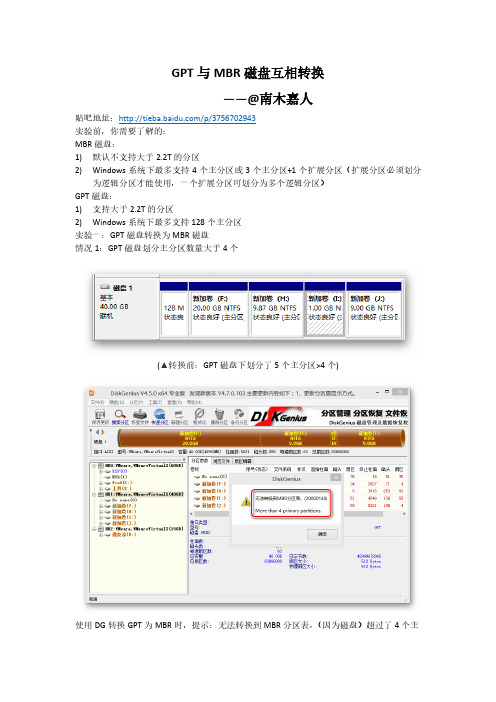
(▲转换前:MBR 磁盘下划分了 3 个主分区+1 个扩展分区)
使用 DG 转换时,提示:转换为 GPT 磁盘后,只有较新的系统才能正常读写(32 位 XP 不支 持 GPT) ;只有基于 EFI 的电脑系统才能从 GPT 磁盘正常启动;如果原 MBR 磁盘存在逻辑分 区,逻辑分区将被转换为主分区,且删除扩展分区 但是,转换可以进行下去,转换为 GPT 磁盘如下图:
GPT 与 MBR 磁盘互相转换 ——@南木嘉人
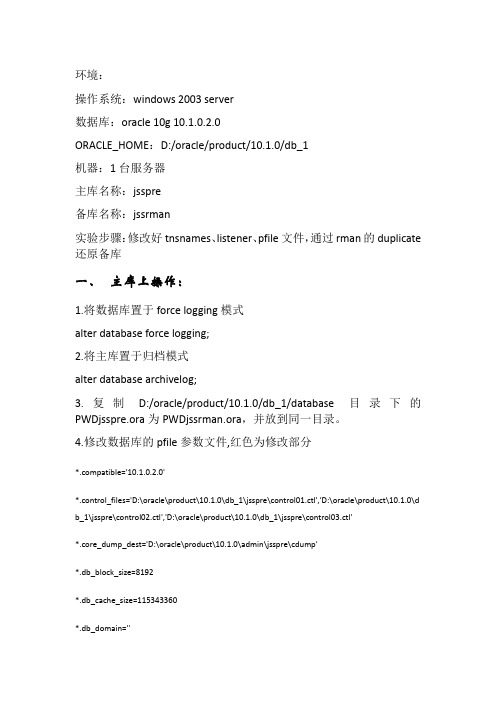
贴吧地址:/p/3756702943 实验前,你需要了解的: MBR 磁盘: 1) 默认不支持大于 2.2T 的分区 2) Windows 系统下最多支持 4 个主分区或 3 个主分区+1 个扩展分区(扩展分区必须划分 为逻辑分区才能使用,一个扩展分区可划分为多个逻辑分区) GPT 磁盘: 1) 支持大于 2.2T 的分区 2) Windows 系统下最多支持 128 个主分区 实验一:GPT 磁盘转换为 MBR 磁盘 情况 1:GPT 磁盘划分主分区数量大于 4 个
(▲在已有 4 个主分区的 MBR 磁盘上进行新分区操作时会提示:基本磁盘将被转换为动态 磁盘,转换为动态磁盘后,我们将无法从这个磁盘的任何分区(除了当前的启动分区)启 动已经安装的系统) 在这里,又出现两个陌生的名词:基本磁盘、动态磁盘 什么是基本磁盘和动态磁盘? 微软官方说明如下: 基本磁盘和动态磁盘是 Windows 中的两种硬盘配置类型。大多数个人计算机都配置为基本 磁盘,该类型最易于管理。高级用户和 IT 专业人员可能使用动态磁盘,他们通常为提高 性能和可靠性而使用计算机中的多个硬盘来管理数据。 只有 Windows Vista Enterprise 和 Windows Vista Ultimate 版本支持动态磁盘。 更多了解请看这里:/zh-CN/windows-vista/What-are-basic-anddynamic-disks 从基本磁盘转换为动态磁盘后, 我们很有可能就无法正常启动系统了, 所以建议大家在这种 情况下,就不要强行转换为动态了。 如果真的要在已有 4 个主分区的 MBR 磁盘上新建分区,建议,你先将某一个主分区转换为 扩展分区,然后在这个扩展分区下创建新的逻辑分区。
安装_扫描枪安装使用教程_2011-12-2

扫描枪安装教程安装PC端的安装分二个部份:A)安装MS ActiveSync;B)配置通讯接口程序;C)配置与SAP 接口。
安装前首先要识别所安装的扫描枪,不同的扫描枪所使用的所使用的通信接口程序是不一样的,1-3代扫描枪使用的是玖龙程序scan,第4代扫描枪使用的接口程序是sapscan。
a.第一代扫描枪,东莞暂时只有六期国废成品库及外租仓库还有在使用,暂无图。
b. 第二代扫描枪c. 第三代扫描枪d. 第四代扫描枪注意从外观各枪上的英文识别扫描枪的型号,现在东莞基地用得比较多的是三代和四代。
1,在管理员权限下安装MSActiveSync(与通讯座连接驱动程序)这是微软提供的标准通讯工具,现在最新的版本是4.5 (Microsoft ActiveSync 4.5),东莞基地枪座连接驱动都用此版本,安装路径:\\Dgfile02\nd_files_5\东莞电脑部\02、技术支持区\30、扫描枪配置文件\扫描枪\Kyman-Net\PC\MS ActiveSync。
安装Microsoft ActiveSync 4.5过程中默认设置即可,直到安装完成后,重启电脑。
ActiveSync 与PC机的连接方式,可以是多样的,直通电缆(串口、USB),机座+电缆(串口、USB );使用USB通讯比较方便。
安装完毕之后,将扫描器轻轻放在机座上,在任务栏上可以看到有个连接的图标,正常连接后图标激活。
使用MS ActiveSync进行连接的时候,要注意一点:打开连接设置:选择可以使用如下端口进行连接:串口COM1或USB连接。
同时,在终端上的控制面板—〉Setting—〉Control Panel—〉PC Connection,选择默认的同桌面电脑的连接方式为USB注:在ActiveSync 连接时,会询问是否建立合作伙伴关系,取消即可。
2,通讯接口程序只需要copy执行程序和相应的动态库即可。
A)由于该程序是利用 开发的,所以必须安装DotNetFrameWrok的环境(\\Dgfile02\nd_files_5\东莞电脑部\02、技术支持区\30、扫描枪配置文件\扫描枪\Kyman-Net\PC\DotNet Framework2.0),安装过程如下:1)、安装DotNetFrameWork 2.0。
windows操作系统下用duplicate创建物理standby数据库
环境:操作系统:windows 2003 server数据库:oracle 10g 10.1.0.2.0ORACLE_HOME:D:/oracle/product/10.1.0/db_1机器:1台服务器主库名称:jsspre备库名称:jssrman实验步骤:修改好tnsnames、listener、pfile文件,通过rman的duplicate 还原备库一、主库上操作:1.将数据库置于force logging模式alter database force logging;2.将主库置于归档模式alter database archivelog;3.复制D:/oracle/product/10.1.0/db_1/database目录下的PWDjsspre.ora为PWDjssrman.ora,并放到同一目录。
4.修改数据库的pfile参数文件,红色为修改部分*.compatible='10.1.0.2.0'*.control_files='D:\oracle\product\10.1.0\db_1\jsspre\control01.ctl','D:\oracle\product\10.1.0\d b_1\jsspre\control02.ctl','D:\oracle\product\10.1.0\db_1\jsspre\control03.ctl'*.core_dump_dest='D:\oracle\product\10.1.0\admin\jsspre\cdump'*.db_block_size=8192*.db_cache_size=115343360*.db_domain=''*.db_file_multiblock_read_count=16*.db_name='jsspre'*.dispatchers='(PROTOCOL=TCP) (SERVICE=jssbookXDB)'*.java_pool_size=50331648*.job_queue_processes=10*.large_pool_size=115343360*.nls_language='SIMPLIFIED CHINESE'*.nls_territory='CHINA'*.open_cursors=300*.pga_aggregate_target=125829120*.processes=150*.remote_login_passwordfile='EXCLUSIVE'*.shared_pool_size=314572800*.sort_area_size=65536*.undo_management='AUTO'*.undo_tablespace='UNDOTBS1'*.user_dump_dest='D:\oracle\product\10.1.0\admin\jsspre\udump'*.DB_RECOVERY_FILE_DEST_SIZE=2147483648*.LOG_ARCHIVE_DEST_1='LOCATION=D:\ORACLE\PRODUCT\10.1.0\DB_1\DATABASE\ARCHIVE VALID_FOR=(ALL_LOGFILES,ALL_ROLES) DB_UNIQUE_NAME=JSSPRE'*.LOG_ARCHIVE_DEST_2='SERVICE=JSSRMAN LGWR ASYNCVALID_FOR=(ONLINE_LOGFILES,PRIMARY_ROLE) DB_UNIQUE_NAME=JSSRMAN'*.LOG_ARCHIVE_DEST_STATE_1=ENABLE*.LOG_ARCHIVE_DEST_STATE_2=ENABLE*.LOG_ARCHIVE_FORMAT='ARC%S%R.%T'*.LOG_ARCHIVE_MAX_PROCESSES=8*.LOG_ARCHIVE_CONFIG='DG_CONFIG=(JSSPRE,JSSRMAN)'*.STANDBY_FILE_MANAGEMENT='AUTO'5.修改完成后shutdown immediatecreate spfile from pfile='上面的参数文件'; startup二、备库操作1.修改刚才的参数文件如下红色部分:*.compatible='10.1.0.2.0'*.db_block_size=8192*.db_cache_size=115343360*.db_domain=''*.db_file_multiblock_read_count=16*.db_name='jsspre'*.dispatchers='(PROTOCOL=TCP) (SERVICE=jssbookXDB)' *.java_pool_size=50331648*.job_queue_processes=10*.large_pool_size=115343360*.nls_language='SIMPLIFIED CHINESE'*.nls_territory='CHINA'*.open_cursors=300*.pga_aggregate_target=125829120*.processes=150*.remote_login_passwordfile='EXCLUSIVE'*.shared_pool_size=314572800*.sort_area_size=65536*.undo_management='AUTO'*.undo_tablespace='UNDOTBS1'*.USER_DUMP_DEST='D:\jssrman\udump'*.LOG_ARCHIVE_CONFIG='DG_CONFIG=(jsspre,jssrman)'*.LOG_ARCHIVE_DEST_1='location=D:\jssrman\archivelogVALID_FOR=(ALL_LOGFILES,ALL_ROLES) DB_UNIQUE_NAME=jssrman'*.LOG_ARCHIVE_DEST_2='SERVICE=jsspre LGWR ASYNCVALID_FOR=(ONLINE_LOGFILES,PRIMARY_ROLE) DB_UNIQUE_NAME=jsspre' *.LOG_ARCHIVE_DEST_STATE_1=ENABLE*.LOG_ARCHIVE_DEST_STATE_2=ENABLE*.LOG_ARCHIVE_MAX_PROCESSES=8*.log_archive_format='arc%s%r.%t'*.STANDBY_FILE_MANAGEMENT='AUTO'*.DB_FILE_NAME_CONVERT='D:\oracle\product\10.1.0\db_1\jsspre','D:\jssrman\oradat a'*.LOG_FILE_NAME_CONVERT='D:\oracle\product\10.1.0\db_1\jsspre','D:\jssrman\orada ta'*.BACKGROUND_DUMP_DEST='D:\jssrman\bdump'*.DB_UNIQUE_NAME='jssrman'*.CONTROL_FILES='D:\jssrman\oradata\stdct01.ctl','D:\jssrman\oradata\stdct02.ctl','D:\js srman\oradata\stdct03.ctl'*.CORE_DUMP_DEST='D:\jssrman\cdump'*.STANDBY_ARCHIVE_DEST='D:\jssrman\archivelog\'*.db_recovery_file_dest='d:\jssrman\flash_recovery_area'*.db_recovery_file_dest_size=2147483648*.audit_file_dest='d:\jssrman\adump'*.audit_trail='db'2.在D:\jssrman目录下建立adump bdump cdump dpump pfile udump oradata archivelogflash_recovery_area文件夹.3.创建oracleservice并加装到nomount状态在CMD中输入oradim -new -sid jssrmanset ORACLE_SID=jssrmansqlplus/@jssrman as sysdbacreate spfile from pfile='参数文件';startup nomountquit三、由于在一台电脑上创建物理standby数据库,修改本电脑的tnsnames、listener文件就可以了。
ASRock H71M-DG3 Motherboard 安装指南说明书

1ASRock H71M-DG3 Motherboard En g l i s h Copyright Notice:No part of this installation guide may be reproduced, transcribed, transmitted, or trans-lated in any language, in any form or by any means, except duplication of documentation by the purchaser for backup purpose, without written consent of ASRock Inc.Products and corporate names appearing in this guide may or may not be registered trademarks or copyrights of their respective companies, and are used only for identi fi ca-tion or explanation and to the owners’ bene fi t, without intent to infringe.Disclaimer:Speci fi cations and information contained in this guide are furnished for informational use only and subject to change without notice, and should not be constructed as a commit-ment by ASRock. ASRock assumes no responsibility for any errors or omissions that may appear in this guide.With respect to the contents of this guide, ASRock does not provide warranty of any kind, either expressed or implied, including but not limited to the implied warranties or condi-tions of merchantability or fi tness for a particular purpose. In no event shall ASRock, its directors, of fi cers, employees, or agents be liable for any indirect, special, incidental, or consequential damages (including damages for loss of pro fi ts, loss of business, loss of data, interruption of business and the like), even if ASRock has been advised of the pos-sibility of such damages arising from any defect or error in the guide or product.This device complies with Part 15 of the FCC Rules. Operation is subject to the following two conditions:(1) this device may not cause harmful interference, and(2) this device must accept any interference received, including interference that may cause undesired operation.CALIFORNIA, USA ONLYThe Lithium battery adopted on this motherboard contains Perchlorate, a toxic substance controlled in Perchlorate Best Management Practices (BMP) regulations passed by the California Legislature. When you discard the Lithium battery in California, USA, please follow the related regulations in advance.“Perchlorate Material-special handling may apply, see/hazardouswaste/perchlorate”ASRock Website: Published April 2012Copyright ©2012 ASRock INC. All rights reserved.Motherboard LayoutEnglish1 1155-Pin CPU Socket 13 Chassis Speaker Header (SPEAKER 1, White)2 ATX 12V Power Connector (ATX12V1) 14 System Panel Header (PANEL1, White)3 CPU Fan Connector (CPU_FAN1) 15 USB 2.0 Header (USB6_7, Blue)4 ATX Power Connector (ATXPWR1) 16 USB 2.0 Header (USB8_9, Blue)5 2 x 240-pin DDR3 DIMM Slots 17 COM Port Header (COM1)(Dual Channel: DDR3_A1, DDR3_B1, Blue) 18 Print Port Header (LPT1, White)6 Intel H61 Chipset 19 Front Panel Audio Header7 32Mb SPI Flash (HD_AUDIO1, White)8 SATA2 Connector (SATA2_1, Blue) 20 PCI Express 2.0 x1 Slot (PCIE2, White)9 Chassis Fan Connector (CHA_FAN1) 21 Clear CMOS Jumper (CLRCMOS1)10 SATA2 Connector (SATA2_0, Blue) 22 PCI Express 3.0 x16 Slot (PCIE1, Blue)11 SATA2 Connector (SATA2_3, Blue) 23 Power Fan Connector (PWR_FAN1)12 SATA2 Connector (SATA2_2, Blue)12345679101112814131516171819202122232ASRock H71M-DG3 Motherboard3ASRock H71M-DG3 Motherboard En g l i s hI/O Panel* There are two LED next to the LAN port. Please refer to the table below for the LAN port LED indications.LAN Port LED IndicationsActivity/Link LED SPEED LED Status Description Status Description Off No Link Off 10Mbps connection Blinking Data Activity Orange 100Mbps connection On Link Green 1Gbps connection ACT/LINK LED SPEED LED LAN Port 1 PS/2 Mouse Port (Green) 7 USB 2.0 Ports (USB23) * 2 LAN RJ-45 Port 8 USB 2.0 Ports (USB01) 3 Line In (Light Blue) 9 DVI-D Port** 4 Front Speaker (Lime) 10 D-Sub Port5 Microphone (Pink) 11 PS/2 Keyboard Port (Purple)6 USB 2.0 Ports (USB45)** To enable Multi-Streaming function, you need to connect a front panel audio cable to the front panel audio header. Please refer to below steps for the software setting of Multi-Streaming. For Windows ® XP:After restarting your computer, you will fi nd “Mixer” tool on your system. Please select “Mixer ToolBox” , click “Enable playback multi-streaming”, and click “ok”. Choose “2CH” or “4CH” and then you are allowed to select “Realtek HDA Primary output” to use Rear Speaker and Front Speaker, or select “Realtek HDA Audio 2nd output” to use front panel audio. Then reboot your system.For Windows ® 7 / Vista TM :After restarting your computer, please double-click “Realtek HD Audio Manager” on the system tray. Set “Speaker Con fi guration” to “Quadraphonic” or “Stereo”. Click “Deviceadvanced settings”, choose “Make front and rear output devices playbacks two different audio streams simultaneously”, and click “ok”. Then reboot your system.4ASRock H71M-DG3 MotherboardEnglish1. Introduction Thank you for purchasing ASRock H71M-DG3 motherboard, a reliable motherboard produced under ASRock’s consistently stringent quality control. It delivers excellent performance with robust design conforming to ASRock’s commitment to quality and endurance.This Quick Installation Guide contains introduction of the motherboard and step-by-step installation guide. More detailed information of the motherboard can be found in the user manual presented in the Support CD. 1.1 Package Contents ASRock H71M-DG3 Motherboard (Micro ATX Form Factor: 8.9-in x 6.8-in, 22.6 cm x 17.3 cm)ASRock H71M-DG3 Quick Installation Guide ASRock H71M-DG3 Support CD 2 x Serial ATA (SATA) Data Cables (Optional)1 x I/O Panel Shield ASRock Reminds You...To get better performance in Windows ® 7 / 7 64-bit / Vista TM / Vista TM 64-bit, it is recommended to set the BIOS option in Storage Con fi guration to AHCI mode. For the BIOS setup, please refer to the “User Manual” in oursupport CD for details.5ASRock H71M-DG3 Motherboard En g l i s h 1.2 Specifications Platform - Micro ATX Form Factor: 8.9-in x 6.8-in, 22.6 cm x 17.3 cm - All Solid Capacitor designCPU - Supports 3rd and 2nd Generation Intel ® Core TM i7 / i5 / i3 in LGA1155 Package- Supports Intel ® Turbo Boost 2.0 Technology- Supports K-Series unlocked CPU- Supports Hyper-Threading Technology (see CAUTION 1) Chipset - Intel ® H61- Supports Intel ® Rapid Start Technology and Smart Connect TechnologyMemory - Dual Channel DDR3 Memory Technology (see CAUTION 2) - 2 x DDR3 DIMM slots- Supports DDR3 1600/1333/1066 non-ECC, un-buffered memory (DDR3 1600 with Intel ® Ivy Bridge CPU, DDR3 1333 with Intel ® Sandy Bridge CPU)- Max. capacity of system memory: 16GB (see CAUTION 3) - Supports Intel ® Extreme Memory Pro fi le (XMP) 1.3 / 1.2 with Intel ® Ivy Bridge CPUExpansion Slot - 1 x PCI Express 3.0 x16 slot (blue @ x16 mode)* PCIE 3.0 is only supported with Intel ® Ivy Bridge CPU. With Intel ® Sandy Bridge CPU, it only supports PCIE 2.0. - 1 x PCI Express 2.0 x1 slotGraphics * Intel ® HD Graphics Built-in Visuals and the VGA outputs can be supported only with processors which are GPU integrated.- Supports Intel ® HD Graphics Built-in Visuals: Intel ® Quick Sync Video 2.0, Intel ® InTru TM 3D, Intel ® Clear Video HD Technology, Intel ® Insider TM , Intel ® HD Graphics 2500/4000 with Intel ® Ivy Bridge CPU- Supports Intel ® HD Graphics Built-in Visuals: Intel ® Quick Sync Video, Intel ® InTru TM 3D, Intel ® Clear Video HDTechnology, Intel ® HD Graphics 2000/3000, Intel ® Advanced Vector Extensions (AVX) with Intel ® Sandy Bridge CPU - Pixel Shader 5.0, DirectX 11 with Intel ® Ivy Bridge CPU. Pixel Shader 4.1, DirectX 10.1 with Intel ® Sandy Bridge CPU.- Max. shared memory 1760MB with Intel ® Ivy Bridge CPU. Max. shared memory 1759MB with Intel ® Sandy Bridge CPU. (see CAUTION 4)English- Dual VGA Output: support DVI-D and D-Sub ports byindependent display controllers- Supports DVI with max. resolution up to 1920x1200 @ 60Hz- Supports D-Sub with max. resolution up to 2048x1536@ 75Hz- Supports HDCP function with DVI port- Supports Full HD 1080p Blu-ray (BD) / HD-DVD playbackwith DVI portAudio - 5.1 CH HD Audio (Realtek ALC662 Audio Codec)LAN - PCIE x1 Gigabit LAN 10/100/1000 Mb/s- Realtek RTL8111C- Supports Wake-On-LAN- Supports PXERear Panel I/O I/O Panel- 1 x PS/2 Mouse Port- 1 x PS/2 Keyboard Port- 1 x D-Sub Port- 1 x DVI-D Port- 6 x Ready-to-Use USB 2.0 Ports- 1 x RJ-45 LAN Port with LED (ACT/LINK LED and SPEEDLED)- HD Audio Jack: Line in/Front Speaker/Microphone Connector- 4 x SATA2 3.0 Gb/s connectors, support NCQ, AHCI andHot Plug functions- 1 x Print Port header- 1 x COM port header- CPU/Chassis/Power FAN connector- 24 pin ATX power connector- 4 pin 12V power connector- Front panel audio connector- 2 x USB 2.0 headers (support 4 USB 2.0 ports) BIOS Feature- 32Mb AMI BIOS- AMI UEFI Legal BIOS with GUI support- Supports “Plug and Play”- ACPI 1.1 Compliance Wake Up Events- Supports jumperfree- SMBIOS 2.3.1 Support- IGPU, DRAM, PCH, CPU PLL, VTT, VCCSA VoltageMulti-adjustment6ASRock H71M-DG3 Motherboard7ASRock H71M-DG3 Motherboard E n g l i s h WARNING Please realize that there is a certain risk involved with overclocking, includingadjusting the setting in the BIOS, applying Untied Overclocking Technology, orusing the third-party overclocking tools. Overclocking may affect your systemstability, or even cause damage to the components and devices of your system.It should be done at your own risk and expense. We are not responsible for possible damage caused by overclocking. Support CD - Drivers, Utilities, AntiVirus Software (Trial Version),CyberLink MediaEspresso 6.5 Trial, Creative Sound Blaster X-Fi MB - Trial, ASRock MAGIX Multimedia Suite - OEM Unique Feature - ASRock Extreme Tuning Utility (AXTU) (see CAUTION 5) - ASRock Instant Boot- ASRock Instant Flash (see CAUTION 6)- ASRock APP Charger (see CAUTION 7)- ASRock SmartView (see CAUTION 8)- ASRock XFast USB (see CAUTION 9)- ASRock XFast LAN (see CAUTION 10)- ASRock XFast RAM (see CAUTION 11)- Hybrid Booster:- ASRock U-COP (see CAUTION 12)- Boot Failure Guard (B.F.G.)- Combo Cooler Option (C.C.O.) (see CAUTION 13) Hardware - CPU Temperature SensingMonitor - Chassis Temperature Sensing- CPU/Chassis/Power Fan Tachometer- CPU/Chassis Quiet Fan (Allow Chassis Fan Speed Auto-Adjust by CPU Temperature)- CPU/Chassis Fan Multi-Speed Control- Voltage Monitoring: +12V, +5V, +3.3V, CPU Vcore OS - Microsoft ® Windows ® 7 / 7 64-bit / Vista TM / Vista TM 64-bit / XP / XP 64-bit compliant (see CAUTION 14)Certi fi cations - FCC, CE, WHQL- ErP/EuP Ready (ErP/EuP ready power supply is required) (see CAUTION 15)* For detailed product information, please visit our website: English8ASRock H71M-DG3 Motherboard9ASRock H71M-DG3 Motherboard En g l i shEnglish14. ASRock XFast RAM is not supported by Microsoft® Windows® XP / XP64-bit.15. EuP, stands for Energy Using Product, was a provision regulated by Eu-ropean Union to defi ne the power consumption for the completed system.According to EuP, the total AC power of the completed system shall beunder 1.00W in off mode condition. To meet EuP standard, an EuP readymotherboard and an EuP ready power supply are required. According toIntel’s suggestion, the EuP ready power supply must meet the standardof 5v standby power effi ciency is higher than 50% under 100 mA currentconsumption. For EuP ready power supply selection, we recommend youchecking with the power supply manufacturer for more details.10ASRock H71M-DG3 Motherboard11ASRock H71M-DG3 Motherboard En g l i s h 2. InstallationPre-installation PrecautionsTake note of the following precautions before you install mother-board components or change any motherboard settings.1. Unplug the power cord from the wall socket before touching anycomponent. Failure to do so may cause severe damage to themotherboard, peripherals, and/or components.2. To avoid damaging the motherboard components due to staticelectricity, NEVER place your motherboard directly on the car-pet or the like. Also remember to use a grounded wrist strap ortouch a safety grounded object before you handle components.3. Hold components by the edges and do not touch the ICs.4. Whenever you uninstall any component, place it on a groundedantstatic pad or in the bag that comes with the component.5. When placing screws into the screw holes to secure the moth-erboard to the chassis, please do not over-tighten the screws!Doing so may damage the motherboard.2.1 CPU InstallationFor the installation of Intel 1155-Pin CPU,please follow the steps below.Before you insert the 1155-Pin CPU into the socket, please check if theCPU surface is unclean or if there is any bent pin on the socket. Do notforce to insert the CPU into the socket if above situation is found. Other-wise, the CPU will be seriously damaged.1155-Pin Socket OverviewEnglishStep 1. Open the socket:Step 1-1. Disengaging the lever by depressingdown and out on the hook to clearretention tab.Step 1-2. Rotate the load lever to fully open po-sition at approximately 135 degrees.Step 1-3. Rotate the load plate to fully open po-sition at approximately 100 degrees.Step 2. Remove PnP Cap (Pick and Place Cap).1. It is recommended to use the cap tab to handle and avoid kickingoff the PnP cap.2. This cap must be placed if returning the motherboard for afterservice.Step 3. Insert the 1155-Pin CPU:Step 3-1. Hold the CPU by the edges whereare marked with black lines.Step 3-2. Orient the CPU with IHS (IntegratedHeat Sink) up. Locate Pin1 and thetwo orientation key notches.For proper inserting, please ensure to match the two orientation keynotches of the CPU with the two alignment keys of the socket.black linePin1alignment keyalignment keyPin11155-Pin CPU1155-Pin Socketorientation key notchorientation key notch12ASRock H71M-DG3 Motherboard13ASRock H71M-DG3 Motherboard En g l i s h Step 3-3. Carefully place the CPU into thesocket by using a purely vertical mo-tion.Step 3-4. Verify that the CPU is within the sock-et and properly mated to the orientkeys.Step 4. Close the socket:Step 4-1. Rotate the load plate onto the IHS.Step 4-2. While pressing down lightly on loadplate, engage the load lever.Step 4-3. Secure load lever with load plate tabunder retention tab of load lever.2.2 Installation of CPU Fan and HeatsinkFor proper installation, please kindly refer to the instruction manuals of your CPU fan and heatsink.Below is an example to illustrate the installation of the heatsink for 1155-Pin CPU.Step 1. Apply thermal interface material onto center ofIHS on the socket surface.Step 2. Place the heatsink onto the socket. Ensure fan cables are oriented on side closest to theCPU fan connector on the motherboard (CPU_FAN1, see page 2, No. 3).Step 3. Align fasteners with the motherboard through-holes.Step 4. Rotate the fastener clockwise, then pressdown on fastener caps with thumb to installand lock. Repeat with remaining fasteners.If you press down the fasteners without rotating them clockwise, theheatsink cannot be secured on the motherboard.Step 5. Connect fan header with the CPU fan connector on the motherboard.Step 6. Secure excess cable with tie-wrap to ensure cable does not interfere withfan operation or contact other components.Please be noticed that this motherboard supports Combo CoolerOption (C.C.O.), which provides the fl exible option to adopt three dif-ferent CPU cooler types, Socket LGA 775, LGA 1155 and LGA 1156.The white throughholes are for Socket LGA1155/1156 CPU fan.14ASRock H71M-DG3 MotherboardEnglish2.3 Installation of Memory Modules (DIMM)This motherboard provides two 240-pin DDR3 (Double Data Rate 3) DIMM slots, and supports Dual Channel Memory Technology. For dual channel configuration, you always need to install two identical (the same brand, speed, size and chip-type) memory modules in the DDR3 DIMM slots to activate Dual Channel Memory Technology. Otherwise, it will operate at single channel mode.1. It is not allowed to install a DDR or DDR2 memory module intoDDR3 slot;otherwise, this motherboard and DIMM may bedamaged.2. If you install only one memory module or two non-identicalmemory modules, it is unable to activate the Dual ChannelMemory Technology.3.Some DDR3 1GB double-sided DIMMs with 16 chips may notwork on this motherboard. It is not recommended to install themon this motherboard.notchInstalling a DIMMPlease make sure to disconnect power supply before adding orremoving DIMMs or the system components.Step 1. Unlock a DIMM slot by pressing the retaining clips outward.Step 2. Align a DIMM on the slot such that the notch on the DIMM matches the break on the slot.The DIMM only fi ts in one correct orientation. It will cause permanent damage to the motherboard and the DIMM if you force the DIMM into the slot at incorrect orientation. Step 3. Firmly insert the DIMM into the slot until the retaining clips at both endsfully snap back in place and the DIMM is properly seated.15ASRock H71M-DG3 Motherboard En g l i sh 2.4 Expansion Slots (PCI Express Slots)There are 2 PCI Express slots on this motherboard.PCIE slots:PCIE1 (PCIE 3.0 x16 slot; Blue) is used for PCI Express x16 lane widthgraphics cards.PCIE2 (PCIE 2.0 x1 slot; White) is used for PCI Express cards with x1lane width cards, such as Gigabit LAN card, SATA2 card, etc.Only PCIE1 slot supports Gen 3 speed. To run the PCI Express in Gen3 speed, please install an Ivy Bridge CPU. If you install a Sandy BridgeCPU, the PCI Express will run only at PCI Express Gen 2 speed.Installing an expansion cardStep 1. Before installing the expansion card, please make sure that the powersupply is switched off or the power cord is unplugged. Please read the documentation of the expansion card and make necessary hardwaresettings for the card before you start the installation.Step 2. Remove the system unit cover (if your motherboard is already installedin a chassis).Step 3. Remove the bracket facing the slot that you intend to use. Keep thescrews for later use.Step 4. Align the card connector with the slot and press fi rmly until the card iscompletely seated on the slot.Step 5. Fasten the card to the chassis with screws.Step 6. Replace the system cover.English2. If you have installed onboard VGA driver from our support CD to your systemalready, you can freely enjoy the benefi ts of dual monitor function after yoursystem boots. If you haven’t installed onboard VGA driver yet, please installonboard VGA driver from our support CD to your system and restart yourcomputer.2.5 Dual Monitor and Surround Display FeaturesDual Monitor FeatureThis motherboard supports dual monitor feature. With the internal VGA output sup-port (DVI-D and D-Sub), you can easily enjoy the benefi ts of dual monitor feature without installing any add-on VGA card to this motherboard. This motherboard also provides independent display controllers for DVI-D and D-Sub to support dual VGA output so that DVI-D and D-sub can drive same or different display contents.To enable dual monitor feature, please follow the below steps:1. Connect DVI-D monitor cable to DVI-D port on the I/O panel, and connect D-Submonitor cable to D-Sub port on the I/O panel.D-Sub port DVI-D port16ASRock H71M-DG3 Motherboard17ASRock H71M-DG3 Motherboard En g l i s h Surround Display FeatureThis motherboard supports surround display upgrade. With the internal VGA output support (DVI-D and D-Sub) and external add-on PCI Express VGA cards, you can easily enjoy the bene fi ts of surround display feature.Please refer to the following steps to set up a surround display environment:1. Install the PCI Express VGA card on PCIE1 slot. Please refer to page 15 for proper expansion card installation procedures for details.2. Connect DVI-D monitor cable to DVI-D port on the I/O panel, and connect D-Sub monitor cable to D-Sub port on the I/O panel. Then connect othermonitor cables to the corresponding connectors of the add-on PCI Express VGA card on PCIE1 slot.3. Boot your system. Press <F2> or <Del> to enter UEFI setup. Enter “Onboard VGA Share Memory” option to adjust the memory capability to [32MB], [64MB],[128MB], [256MB] or [512MB] to enable the function of D-sub. Please make sure that the value you select is less than the total capability of the system memory. If you do not adjust the UEFI setup, the default value of “Onboard VGA Share Memory”, [Auto], will disable D-Sub function when the add-on VGA card is inserted to this motherboard.4. Install the onboard VGA driver and the add-on PCI Express VGA card driver to your system. If you have installed the drivers already, there is no need to install them again.5. Set up a multi-monitor display.For Windows ® XP / XP 64-bit OS:Right click the desktop, choose “Properties”, and select the “Settings” tab so that you can adjust the parameters of the multi-monitor according to the steps below.A. Click the “Identify” button to display a large number on each monitor.B. Right-click the display icon in the Display Properties dialog that you wish to be your primary monitor, and then select “Primary”. When you use multiple monitors with your card, one monitor will always be Primary, and all additional monitors will be designated as Secondary.C. Select the display icon identi fi ed by the number 2.D. Click “Extend my Windows desktop onto this monitor”.E. Right-click the display icon and select “Attached”, if necessary.F. Set the “Screen Resolution” and “Color Quality” as appropriate for the second monitor. Click “Apply” or “OK” to apply these new values.G. Repeat steps C through E for the diaplay icon identi fi ed by the number one, two, three and four.EnglishFor Windows® 7 / 7 64-bit / Vista TM / Vista TM 64-bit OS:Right click the desktop, choose “Personalize”, and select the “DisplaySettings” tab so that you can adjust the parameters of the multi-monitoraccording to the steps below.A. Click the number ”2” icon.B. Click the items “This is my main monitor” and “Extend the desktop ontothis monitor”.C. Click “OK” to save your change.D. Repeat steps A through C for the display icon identifi ed by the numberthree and four.6. Use Surround Display. Click and drag the display icons to positions representingthe physical setup of your monitors that you would like to use. The placementof display icons determines how you move items from one monitor to another.HDCP FunctionHDCP function is supported on this motherboard. To use HDCPfunction with this motherboard, you need to adopt the monitorthat supports HDCP function as well. Therefore, you can enjoythe superior display quality with high-defi nition HDCPencryption contents. Please refer to below instruction for moredetails about HDCP function.WhatisHDCP?HDCP stands for High-Bandwidth Digital Content Protection,aspecifi cation developed by Intel® for protecting digitalentertainment content that uses the DVI interface. HDCP is acopy protection scheme to eliminate the possibility ofintercepting digital data midstream between the video source,or transmitter - such as a computer, DVD player or set-top box -and the digital display, or receiver - such as a monitor, televisionor projector. In other words, HDCP specifi cation is designed toprotect the integrity of content as it is being transmitted.Products compatible with the HDCP scheme such as DVDplayers, satellite and cable HDTV set-top-boxes, as well as fewentertainment PCs requires a secure connection to a compliantdisplay. Due to the increase in manufacturers employing HDCPin their equipment, it is highly recommended that the HDTV orLCD monitor you purchase is compatible.18ASRock H71M-DG3 Motherboard19ASRock H71M-DG3 Motherboard En g l i s h 2.6 Jumpers SetupThe illustration shows how jumpers aresetup. When the jumper cap is placed onpins, the jumper is “Short”. If no jumper capis placed on pins, the jumper is “Open”. Theillustration shows a 3-pin jumper whosepin1 and pin2 are “Short” when jumper capis placed on these 2 pins.Jumper Setting Description Clear CMOS Jumper(CLRCMOS1)(see p.2, No. 21)Note: CLRCMOS1 allows you to clear the data in CMOS. To clear and reset the system parameters to default setup, please turn off the computer and unplugthe power cord from the power supply. After waiting for 15 seconds, use a jumper cap to short pin2 and pin3 on CLRCMOS1 for 5 seconds. However, please do not clear the CMOS right after you update the BIOS. If you need to clear the CMOS when you just fi nish updating the BIOS, you must boot up the system fi rst, and then shut it down before you do the clear-CMOS ac-tion. Please be noted that the password, date, time, user default pro fi le, 1394 GUID and MAC address will be cleared only if the CMOS battery is removed.Clear CMOSDefault20ASRock H71M-DG3 MotherboardEnglish2.7 Onboard Headers and ConnectorsOnboard headers and connectors are NOT jumpers. Do NOT placejumper caps over these headers and connectors. Placing jumper capsover the headers and connectors will cause permanent damage of themotherboard!Serial ATAII ConnectorsThese four Serial ATAII (SATA2_0: see p.2, No. 10)(SATAII) connectors support (SATA2_1: see p.2, No. 8)SATA data cables for internal (SATA2_2: see p.2, No. 12)storage devices. The current (SATA2_3: see p.2, No. 11) SATAII interface allows up to3.0 Gb/s data transfer rate.Serial ATA (SATA) Either end of the SATA data Data Cable cable can be connected to the (Optional) SATA / SATAII hard disk or the SATAII connector on thismotherboard.USB 2.0 HeadersBesides six default USB 2.0 (9-pin USB6_7)ports on the I/O panel, there (see p.2 No. 15) are two USB 2.0 headers onthis motherboard. EachUSB 2.0 header can supporttwo USB 2.0 ports.(9-pin USB8_9)(see p.2 No. 16)1USB_PWR P-8GND DUMMYUSB_PWR P+8GND P-9P+9SATA2_1SATA2_0SATA2_3SATA2_2Print Port Header This is an interface for print (25-pin LPT1) port cable that allows (see p.2 No. 18) convenient connection of printer devices.1AFD#ERROR#PINIT#GND SLIN#STB#SPD0SPD1SPD2SPD3SPD4SPD5SPD6SPD7ACK#BUSY PE SLCT21ASRock H71M-DG3 Motherboard En g l i s h J_SENSEOUT2_L 1MIC_RETPRESENCE#GND OUT2_RMIC2_R MIC2_LOUT_RET Front Panel Audio Header This is an interface for front (9-pin HD_AUDIO1) panel audio cable that allows(see p.2 No. 19) convenient connection and control of audio devices.System Panel Header This header accommodates (9-pin PANEL1) several system front panel (see p.2 No. 14)functions.Connect the power switch, reset switch and system status indicator on thechassis to this header according to the pin assignments below. Note thepositive and negative pins before connecting the cables.PWRBTN (Power Switch):Connect to the power switch on the chassis front panel. You may con fi gurethe way to turn off your system using the power switch.RESET (Reset Switch):Connect to the reset switch on the chassis front panel. Press the resetswitch to restart the computer if the computer freezes and fails to perform anormal restart.PLED (System Power LED):Connect to the power status indicator on the chassis front panel. The LEDis on when the system is operating. The LED keeps blinking when the sys-tem is in S1 sleep state. The LED is off when the system is in S3/S4 sleepstate or powered off (S5).1. High De fi nition Audio supports Jack Sensing, but the panel wire onthe chassis must support HDA to function correctly. Please follow theinstruction in our manual and chassis manual to install your system.2. If you use AC’97 audio panel, please install it to the front panel audioheader as below:A. Connect Mic_IN (MIC) to MIC2_L.B. Connect Audio_R (RIN) to OUT2_R and Audio_L (LIN) to OUT2_L.C. Connect Ground (GND) to Ground (GND).D. MIC_RET and OUT_RET are for HD audio panel only. You don’tneed to connect them for AC’97 audio panel.E. To activate the front mic.For Windows ® XP / XP 64-bit OS:Select “Mixer”. Select “Recorder”. Then click “FrontMic”.For Windows ® 7 / 7 64-bit / Vista TM / Vista TM 64-bit OS:Go to the "FrontMic" Tab in the Realtek Control panel. Adjust“Recording Volume”.。
USB编程电缆驱动程序安装说明书-232
USB编程电缆驱动程序安装说明概述USB编程电缆是通过将电脑的USB接口模拟成传统的串行口(通常为COM3),从而使用现有的编程软件或通信软件,通过编程电缆与PLC等设备的传统接口进行通信。
功能●支持的操作系统Windows2000/Windows XP●完全兼容USB V1.1和USB CDC V1.1规范●USB总线供电(非隔离电缆)、或USB总线供电与PLC的编程口同时供电(隔离型电缆)●波特率:300bps~1Mbps自动适应●每台PC只支持一根USB编程电缆系统要求请在使用USB编程电缆之前确认你的电脑是IBM PC兼容型并具备以下最低系统要求:●Intel兼容586DX4-100MHz中央处理器或更高●一个标准的USB接口(4-pin A型插座)●运行操作系统为Windows2000或Windows XP驱动程序的安装驱动程序的安装非常简单,只需按提示进行即可,以Windows XP为例,按以下步骤进行:安装驱动会安装两次,一次安装串行总线控制器里的驱动。
第二次安装端口(也称串口)。
请安以下步骤安装1、打开将要连接USB编程电缆的电脑电源,并确认电脑的USB口已经启动并正常工作。
2、将USB编程电缆插入电脑的USB接口,Windows将检测到设备并运行添加新硬件向导帮助你设置新设备,插入驱动程序光盘并单击下一步继续。
如果Windows没有提示找到新硬件,那么在设备管理器的硬件列表中,展开“通用串行总线控制器”,选择带问号的USB设备,单击鼠标右键并运行更新驱动程序。
3、选择”否,暂时不”,然后点下一步。
3、Windows将检测到安装信息,显示“DGYCGK USB High Speed SerialConverter ”设备,并出现如下没有通过Windows徽标测试的信息框,单击“从列表或指定位置安装(高级)”。
4、把上面两个选项打上钓,在“浏览”里把路径指向光盘所对应的驱动,然后点“下一步”。
田岛刺绣软件
DG/ML 花样设计软件用户手册
此手册叙述下述产品功能 ! 达 5 级级别的花样设计软件能力 ! 花样设计资源管理器 只对正常绣花 ( 没有 Chenille)
DG/ML 机器管理器补充材料
此手册的补充材料叙述下述产品功能 ! 机器管理器直接连接 ! 来自绣花机反馈 ! 机器操作报告 ! 机器网络设定的技术细节 当用户购买机器管理器直接连接选项时 提供给他们机器管理器补充 材料 不要单独使用此手册 应当和花样设计软件用户手册一起使用 不需要其它组件
把花样设计另存为位图图象
DG/ML 是您可以把花样设计图象保存到磁盘或直接用电子邮件传送 可 以作为有或没有背景颜色或织物的位图来俘获图象 可以用 TrueView TM 或其它方法来俘获 包括连接线 轮廓线和 DG/ML 中提供的任何 其它显示选项
花样设计管理
DG/ML 花样设计浏览软件已经分别被 花样设计资源管理器 要比以前的功能多得多 排序 定位和显示 可以更快地为花样设计
8100600
DG/ML 版本注解 V7.0
DG/MLV7.0 的内容
此章详细叙述生产组件包 有值选项和 V7.0DG/ML 组件包的组件
DEll DG_存储系列指南
Dell™ PowerVault™ MD3200和 MD3220 存储阵列部署指南注:“注”表示帮助您更好地使用计算机的重要信息。
警告:“注意”表示如果不遵循说明,就有可能损坏硬件或导致数据丢失。
警告:“警告”表示可能会造成财产损失、人身伤害甚至死亡。
____________________本说明文件中的信息如有更改,恕不另行通知。
© 2010 Dell Inc. 版权所有,翻印必究。
未经 Dell Inc. 书面许可,严禁以任何形式复制这些材料。
本文中使用的商标:Dell、DELL徽标、和 PowerVault 是 Dell Inc. 的商标;Intel和Pentium 是 Intel Corporation 在美国和其他国家/地区的注册商标;Microsoft、Windows、和Windows Server是 Microsoft Corporation 在美国和/或其他国家/地区的商标或注册商标;Red Hat和Red Hat Enterprise Linux是 Red Hat, Inc. 在美国和其他国家/地区的注册商标;SUSE是Novell, Inc.在美国和其他国家/地区的注册商标;VMware是 VMware, Inc. 在美国和/或其他辖区的注册商标或商标(“标志”);Citrix是 Citrix Systems, Inc. 和/或其多个子公司的商标,并且可能已在美国专利商标局及其他国家/地区注册。
本说明文件中可能使用其他商标和商品名称来指拥有相应商标和商品名称的公司或其产品。
Dell Inc. 对其他公司的商标和商品名称不拥有任何所有权。
2010 年 6 月 修订版 A00目录1简介 (5)系统要求 (5)Management Station 要求 (5)存储阵列简介 (6)2硬件安装 (7)存储设备配置规划 (7)关于存储阵列连接 (8)存储阵列布线 (8)冗余和非冗余配置 (8)单控制器配置 (9)双控制器配置 (12)PowerVault MD1200 系列扩展柜布线 (18)使用之前已配置的 PowerVault MD1200系列扩展柜进行扩充 (18)使用新的 PowerVault MD1200系列扩展柜进行扩充 (19)3软件安装 (21)在 iSCSI 型主机服务器上 (21)图形化安装(推荐) (22)控制台安装 (22)无提示安装 (23)格瞒34安装后任务 (25)验证存储阵列搜索 (26)初始设置任务 (26)5卸载软件 (29)从 Microsoft Windows 中卸载 (29)从 Linux 卸载 (30)A附录—负载均衡 (31)Windows 负载均衡策略 (31)带子集的循环 (31)带子集的最少队列深度 (31)修改 Windows Sever 2008的负载均衡策略 (32)在 Linux 中设置负载均衡策略 (32)4格瞒简介5简介本指南提供部署 Dell™ PowerVault™ MD3200 和MD3220 存储阵列的相关信息。
WinSock网络编程
WinSock 网络编程1. 概述80's 初,ARPA(美国国防部高级研究计划局)®加利福尼亚大学Berkeley 分校提供资金,®开发在UNIX 下实现TCP/IP 协议。
®为TCP/IP 开发了一个API –– Socket 接口(套接口)–– 俗称Bekeley 套接口模型。
90's 初,Microsoft 等公司®基于Bekeley 套接口模型®制定了Windows Sockets 规范(简称WinSock)®已是TCP/IP 网络的标准。
1993.1,v1.1 1995.5,v2.0,增加了QOS (网络服务质量控制)2. WinSock 模型提供TCP/IP 传输层的接口:①TCP(传输控制协议)提供虚电路和面向连接的数据流传输服务。
实现无差错无重复的顺序数据传输。
Z D r i v e r eo n.c o m .②UDP(用户数据报协议)提供无连接的数据报传输服务。
数据通过相互独立的报文进行传输,是无序的,并且不保证可靠、无差错。
3. WinSock DLL·WinSock 与操作系统的关系动态链接库·动态链接库: 16位版:WINSOCK.DLL 32位版:WSOCK32.DLL①DLL 装载WinSock 服务由动态连接库WinSock DLL 提供,它完成WinSock 的初始化任务,协商WinSock 的版本支持,并分配必要的资源。
在使用WinSock API 之前,必须调用:· int WSAStartup(WORD v, (LPWSADATA)&WD)其中:v ––– 指示应用程序对WinSock 版本的要求, 低字节为主版本号,高字节为副版本号。
例:v1.1 ® v=Ox0101, v2.0 ® v=Ox0002,WD ––返回WinSock 的实现信息。
- 1、下载文档前请自行甄别文档内容的完整性,平台不提供额外的编辑、内容补充、找答案等附加服务。
- 2、"仅部分预览"的文档,不可在线预览部分如存在完整性等问题,可反馈申请退款(可完整预览的文档不适用该条件!)。
- 3、如文档侵犯您的权益,请联系客服反馈,我们会尽快为您处理(人工客服工作时间:9:00-18:30)。
精心整理物理standby 创建及维护一:服务器的环境配置双机DATAGUARD 配置,首先需要满足的基础环境就是两台独立运行且互访通畅的服务器。
参照即将作为主机的服务器配置,包括系统版本,内存配置,硬盘空间等软硬件参数对我们的备库服务器进行准备。
因为实际应用环境中,当主机出现不可挽回的故障后,备机将切换成为主机,承受主机等同的运行负荷。
二: 三:1、将1.11.223、配置oracle 1确保2创建适当的日志组,一般而言,standbyredo 日志文件组数要比primary 数据库的onlineredo 日志文件组数至少多一个。
Standbyredolog 的操作方式与onlineredolog 几乎一模一样,只不过在创建或删除时需要多指定一个standby 关键字,例如添加:SQL>alterdatabaseaddstandbylogfile('e:\lmis\STANDBYREDO01.LOG')size50M;删除也同样简单:SQL>alterdatabasedropstandbylogfilegroup4;验证standbyredolog 文件组是否成功创建SQL>SELECTGROUP#,THREAD#,SEQUENCE#,ARCHIVED,STATUSFROMV$STANDBY_LOG;4、创建primary数据库客户端初始化参数文件注:主要此处修改项较多,为了方便,我们首先创建并修改pfile,然后再通过pfile重建spfile,你当然也可以通过altersystemset命令直接修改spfile内容。
SQL>createpfile=’e:\lmis.ora’fromspfile;文件已创建。
下列参数为primary角色需添加的相关初始化参数:DB_UNIQUE_NAME=lmisprmLOG_ARCHIVE_CONFIG='DG_CONFIG=(lmisprm,lmisstd)'LOG_ARCHIVE_DEST_1='LOCATION=E:\lmis\archive以下参数为转为Standby)等数5确定-----selectFILE_NAMEfromdba_data_filesunionallselectTABLESPACE_NAME表空间,FILE_NAME数据文件,BYTES/1024/1024容量fromdba_temp_files)orderby表空间,数据文件表空间数据文件容量1 DATA E:\LMIS\DATAFILE\INF01.DBF 10242 INDX E:\LMIS\DATAFILE\INDX01.DBF 5123 LMIS E:\LMIS\DATAFILE\DATA01.DBF 20484 LMIS E:\LMIS\DATAFILE\DATA02.DBF 10245 LMIS E:\LMIS\DATAFILE\DATA03.DBF 10246 RBSG E:\LMIS\DATAFILE\RGSG01.DBF 20487 SYSAUX E:\LMIS\DATAFILE\SYSAUX01.DBF 10248 SYSTEM E:\LMIS\DATAFILE\SYSTEM01.DBF 10249 TEMP E:\LMIS\DATAFILE\TEMP01.DBF 102410 TOOLS E:\LMIS\DATAFILE\TOOLS01.DBF 1024-----联机重做日志文件SELECTgroup#,status,type,memberFROMV$LOGFILE;GROUP# STATUS TYPE MEMBER1 1 ONLINE E:\LMIS\LOGFILE\REDO01.LOG2 2 ONLINE E:\LMIS\LOGFILE\REDO02.LOG345676如果当前7通过1服2SQL>ALTERDATABASECREATESTANDBYCONTROLFILEAS'E:\LMIS\LOGFILE\CONTROL01.CTL';注意哟,控制文件通常需要有多份,你要么手工将上述文件复制几份,要么用命令多创建几个出来。
另外,创建完控制文件之后到standby数据库创建完成这段时间内,要保证primary数据库不再有结构性的变化(比如增加表空间等等),不然primary和standby同步时会有问题。
3、创建初始化参数文件注:主要此处修改项较多,为了方便,我们首先创建并修改pfile,然后再通过pfile重建spfile,你当然也可以通过altersystemset命令直接修改spfile内容。
primary服务器执行SQL>createpfilefromspfile;文件已创建。
修改初始化参数文件中的参数(黑色加粗字体为需要修改的内容)DB_NAME=lmisDB_UNIQUE_NAME=lmisstdLOG_ARCHIVE_CONFIG='DG_CONFIG=(lmisprm,lmisstd)'CONTROL_FILES='E:\LMIS\LOGFILE\CONTROL01.CTL','E:\LMIS\LOGFILE\CONTROL02.CTL'DB_FILE_NAME_CONVERT='E:\lmis\datafile','E:\lmis\datafile'LOG_FILE_NAME_CONVERT='E:\lmis\logfile','E:\lmis\logfile'LOG_ARCHIVE_FORMAT='ARC%S_%R.%T'LOG_ARCHIVE_DEST_1='LOCATION=E:\lmis\archiveVALID_FOR=(ALL_LOGFILES,ALL_ROLES)DB_UNIQUE_NAME=lmisstd'数比如45、配置5.1通过5.1复位置是5.3配置Standby服务器和primary服务器都需要配置,一个监听,两个服务名(pri,std),服务名要使用dedicate模式(SERVER=DEDICATED)。
5.4通过该pfile创建spfileSQL>createspfilefrompfile='D:\backup\initjsspdg.ora';文件已创建。
6、启动standby注意哟,咱们前面说过的,物理standby极少情况下可以以read-write模式打开,某些情况下可以以readonly模式打开,所以默认情况下,加载到mount状态即可,11G可以打开数据库。
SQL>STARTUP;7启动日志实时应用SQL>ALTERDATABASERECOVERMANAGEDSTANDBYDATABASEUSINGCURRENTLOGFILEDISCONNECTFROMSESSION;提示:disconnectfromsession子句并非必须,该子句用于指定启动完应用后自动退出到命令操作符前,如果不指定的话,当前session就会一直停留处理redo应用,如果想做其它操作,就只能新建一个连接。
8、查看同步情况8.1连接到primary数据库,查询已经存在的归档日志文件。
SQL>SELECTSEQUENCE#,FIRST_TIME,NEXT_TIMEFROMV$ARCHIVED_LOGORDERBYSEQUENCE#;8.2连接到standby数据库,查询已经存在的归档日志文件。
SQL>SELECTSEQUENCE#,FIRST_TIME,NEXT_TIME-8.3在8.4,在8.5在SEQUENCE#APP------------8YES9YES10YES11IN-MEMORY提示:APPLIED列值为YES或IN-MEMORY表明对应的归档日志已经被应用五:第二部分物理角色转换1,角色转换前的准备工作1.1检查各数据库的初始化参数,主要确认对不同角色相关的初始化参数都进行了正确的配置。
1.2确保可能成为primary数据库的standby服务器已经处于archivelog模式。
1.3确保standby数据库的临时文件存在并匹配primary数据库的临时文件。
2,物理standby的Switchover2.1检查是否支持switchover操作--primary数据库操作SQL>SELECTSWITCHOVER_STATUSFROMV$DATABASE;SWITCHOVER_STATUS-----------------TOSTANDBY1rowselected角色,2.2启动首先将2.32.4待原看看是,如否则检查其初始化参数文件中的设置,提示一下,比着原primary数据库的初始化参数改改。
2.5转换角色到primary--待转换standby数据库操作通过下列语句转换standby到primary角色:SQL>ALTERDATABASECOMMITTOSWITCHOVERTOPRIMARYWITHSESSIONSHUTDOWN;数据库已更改。
2.6完成转换,打开新的primary数据库SQL>alterdatabaseopen;数据库已更改。
注:如果数据库处于openread-only模式的话,需要先shutdown然后直接startup即可。
2.7备机上启动日志实时应用SQL>ALTERDATABASERECOVERMANAGEDSTANDBYDATABASEUSINGCURRENTLOGFILEDISCONNECTFROMSESSION;3,物理standby的failoverfailover之后,原primary数据库默认不再是dataguard配置的一部分。
如果待转换角色的standby处于maximumprotection或maximumavailability模式的话,归档日志应该是连续存在的,这种情况下你可以直接从第3步执行,否则建议你按照操作步骤从第1步开始执行。
一般情况下failover都是表示primary数据库瘫痪,最起码也是起不来了,因此这种类型的不影响3.119092这一步非常重要,3.2分别在必须primary数据库此时已经无法打开,甚至无法访问,那你只好听天由命喽。
3.3停止备机日志应用SQL>ALTERDATABASERECOVERMANAGEDSTANDBYDATABASECANCEL;3.4启动failover执行下列语句:SQL>ALTERDATABASERECOVERMANAGEDSTANDBYDATABASEFINISH;数据库已更改。