EEPROM分析仪使用方法
ilentEB网络分析仪使用方法精编版

i l e n t E B网络分析仪使用方法公司内部编号:(GOOD-TMMT-MMUT-UUPTY-UUYY-DTTI-前面板:部件的名称和功能按键工作通道/迹线区用于选择工作通道和迹线的一组按键。
输入区E5061B 的前面板上提供了用于输入数字数据的一组按键。
仪器状态区与宏程序功能、存储和调用功能、控制/管理功能以及预设 E5061B(将其返回到预设状态)相关的一组按键。
标记/分析区用于通过使用标记等来分析测量结果的一组按键。
最小值、峰值和带有目标值的点)。
还可以查找带宽参数(最多六个)并显示它们。
Marker Fctn 在中显示“Marker Fctn”菜单。
通过操纵“Marker Function”菜单,不仅可以指定通道中的标记扫描范围和标记耦合,还可以显示迹线上的统计数据。
Analysis在中显示“Analysis”菜单。
通过操纵“Analysis”菜单,可以使用故障定位、SRL 和每个极限测试的分析功能。
浏览区(前面板上没有标签)浏览区中的按键和旋钮用于在功能键菜单、表格(极限表、分段表等)或对话框中的选定(高亮显示的)区域中进行浏览,以及通过增加或减少来更改数据输入区域中的数值。
当使用屏幕上显示的浏览区按键,从两个或多个对象(功能键菜单、数据输入区域等)中选择一个要操纵对象的时,首先按中的 Foc(聚焦)键,以选择要操纵的对象(将焦点置于该对象上),然后操纵浏览区按键(旋钮),在选定(高亮显示)的对象之间移动或更改数值。
下面的描述说明了当焦点在功能键菜单上时和当焦点在数据输入区域中时浏览区按键的作用。
有关操纵表和对话框的更多信息,请参考所有这些功能的操纵步骤。
按键名称说明旋钮(顺时针旋转或逆时针转上下移动对功能键的选择(高亮显示)。
动)上/下箭头键上下移动对功能键的选择(高亮显示)。
右箭头键显示上一层功能键菜单。
左箭头键显示下一层功能键菜单。
Enter或旋钮(按下)执行选定功能键的功能。
EEPROM实验说明

“EEPROM只读存储器的应用”实验说明实验内容一按照实验教程的要求,完成在文件缓冲区第1行输入16个字形码,实验箱数码管上分别显示0、1、2、……e、F等十六个字符。
实验步骤如下:1.数据下载⑴ .将实验箱左下角的拨动开关置于左侧“编程”方式。
⑵.双击桌面TopWin6 图标→弹出TopWin Ver6.33T窗口。
⑶.选择器件:在主菜单“操作”栏中点击“选择器件”,弹出TOP0窗口,选择芯片类型“电擦除存储器”→选择芯片公司“ATMEL”→选择芯片型号“AT28C64B”→确认。
或者点击“选择芯片的型号”图标,弹出sellecte chip窗口,点击“ALL”→点击“ATMEL”→点击“AT28C64B”→确定。
⑷.在主菜单“操作”栏中点击“擦除器件”或者点击“擦除器件”图标。
⑸.在文件缓冲区第1行,用鼠标左键点亮第一个FF,将实验教程中的编程数据(八段共阴字形码)共计16个,去掉前面的0和后面的H,变成如FD、61、DB、F3 …从左至右依次正确输入。
⑹. 在主菜单“操作”栏中点击“写器件”→点击“校对”→点击“读器件”。
或者点击“写器件”图标→点击“比较器件与缓冲区数据”图标→点击“读器件中内容到缓冲区”图标。
2.硬件电路接线,实验结果⑴.将实验箱左下角的拨动开关置于右侧“实验”方式,此时位于开关右边的灯亮。
⑵.实验连线:将EEPROM芯片的地址输入端A3、A2、A1、A0分别连接4个开关;将芯片的数据输出端O7、O6…O1、O0分别连接共阴八段数码管的a、b…g、h(Dp)端。
⑶.打开实验箱电源(在实验箱后面)。
⑷.在开关上改变EEPROM的地址输入从0000到1111共计16个状态,八段共阴数码管上分别显示0、1、2、……e、F等十六个字符。
实验内容二完成在文件缓冲区第n行上述输入16个字形码,在实验箱数码管上分别显示0、1、2、……e、F等十六个字符。
实验步骤同上,要注意的是实验连线时,要使芯片的地址必须与字形码在缓冲区的地址相符。
网络分析仪详细操作使用(E5062A)

添加副标题
CLICK HERE TO ADD TITLE
CONTENTS
目录
1
WORKREVIEW
添加标题
2
添加标题
UNDERWORK
测量时注意输入功率、电压、电流不要超过设备给出的最高参考值;
02
做好静电防护。设备中的高敏感微电路在测试连接或者断开连接时易被静电损坏,故操作时应佩带接地手环 ,设备机壳地应与电源地连接完好;
NAVIGATION按钮区
当focus选定屏幕菜单时,其最上方的菜单标题区域显示为蓝色(未选定时为灰色),导航区按钮工作如下所述:
当focus选定屏幕菜单时
.选择旋钮:屏幕菜单子选项上下移动(高亮显示) .上、下键:屏幕菜单子选项上下移动(高亮显示) .向左键:显示屏幕菜单上一层菜单 .向右键:显示屏幕菜单下一次子菜单 .按压旋钮或Enter:选定当前高亮的子选项 当按下数据输入子选项后,focus自动转移到数据输入区域。 2)当focus选定数据输入区域时 当focus选定数据输入区域时,数据输入框变为蓝色,导航区按钮工作如下所述: .选择旋钮:以较小的步进值增大或减小数据输入区内的数值 .上、下键:以较大的步进值增大或减小数据输入区内的数值 .左、右键:在数据输入区内移动光标(|),与输入区的按钮一起使用可以每次改变输入数据的一位数值。
然后,根据需要断开后面板的电源线。
在正常使用情况下,禁止在开机状态下直接拔掉后面板的电源线,始终保持后面板的电源开关处于ON。如果直接拔线或者关闭后面板的开关,关机持续将不工作,这可能损坏设备的软硬件,并导致设备故障。
错误的关机方式将导致再次开机后进入“安全模式”。在这种情况下,先正常关机使其进入standby状态,然后再次开机可进入正常工作模式。
安吉芯电子8560E EC-系列频谱分析仪安全功能与易失性特性指南说明书

1981Table of ContentsContacting Agilent Sales and Service Offices (3)Products Covered by this Document (4)Security Terms and Definitions (5)Instrument Memory (6)Memory Clearing, Sanitization and Removal Procedures (9)User and Remote Interface Security Measures (12)Deleting User Information (12)Screen and Annotation Blanking (13)SCPI/GPIB Control of Interfaces (13)Remote Access Interfaces (14)Procedure for Declassifying a Faulty Instrument (15)References (16)Contacting Agilent Sales and Service OfficesAssistance with test and measurement needs and information on finding a local Agilent office is available on the internet at:/find/assist.If you do not have internet access, please contact your field engineer.Note: In any correspondence or telephone conversation, refer to the instrument by its model number and full serial number. With this information, the Agilent representative can determine whether your unit is still within its warranty period.3Products Covered by this DocumentProduct Family Name Product Names Model NumbersPortable Spectrum Analyzers 8560E-Series Spectrum Analyzer 8560E, 8561E, 8562E, 8563E, 8564E, 8565E8560EC-Series Spectrum Analyzer 8560EC, 8561EC, 8562EC, 8563EC, 8564EC,8565EC(All models were sold with either Agilent or Hewlett-Packard branding.)This document describes instrument security features and the steps to declassify an instrument through memory sanitization or removal. It provides a statement regarding the volatility of all memory types, and specifies the steps required to declassify an instrument through memory clearing, sanitization, or removal.For additional information, go to:/find/securityNote: Be sure that all information stored by the user in the instrument that needs to be saved is properly backed up before attempting to clear any of the instrument memory. Agilent Technologies cannot be held responsible for any lost files or data resulting from the clearing of memory. Be sure to read this document entirely before proceeding with any file deletion or memory clearing.4Security Terms and DefinitionsTerm DefinitionClearing As defined in Section 8-301a of DoD 5220.22-M, clearing is the process of eradicating the data on media before reusing the media so that the data can no longer be retrieved using the standardinterfaces on the instrument. Clearing is typically used when the instrument is to remain in anenvironment with an acceptable level of protection.Instrument Declassification A term that refers to procedures that must be undertaken before an instrument can be removed from a secure environment, such as is the case when the instrument is returned for calibration. Declassification procedures include memory sanitization or memory removal, or both. Agilent declassification procedures are designed to meet the requirements specified in DoD 5220.22-M, Chapter 8.Sanitization As defined in Section 8-301b of DoD 5220.22-M, sanitization is the process of removing or eradicating stored data so that the data cannot be recovered using any known technology.Instrument sanitization is typically required when an instrument is moved from a secure to anon-secure environment, such as when it is returned to the factory for calibration.Agilent memory sanitization procedures are designed for customers who need to meet therequirements specified by the US Defense Security Service (DSS). These requirements arespecified in the “Clearing and Sanitization Matrix” in Section 5.2.5.5.5 of the ISFO ProcessManual.Secure Erase Secure Erase is a term that is used to refer to either the clearing or sanitization features of Agilent instruments.56Instrument MemoryThis section contains information on the memory components present in your instrument.The tables provide details of the size of each memory component, its type, how it is used, its location, volatility, and the sanitization procedure.Table 1: Instrument Memory - Base InstrumentMemory Type and SizeW r i t a b l e D u r i n g N o r m a l O p e r a t i o nD a t a R e t a i n e d W h e n P o w e r e d O f fPurpose/ContentsData Input MethodLocation in Instrument and RemarksSanitization ProcedureMain Memory (UVEPROM) (E-Series) 12 Mbit No Yes Firmware operating memory Programmed beforeinstalled (no user files) A2 Controller Board Contains no user dataNoneMain Memory (Flash) (EC-Series) 16 Mbit No Yes Firmware operating memory Programmed beforeinstalled (no user files) A2 Controller Board Contains no user dataNoneBattery-backed Display Memory (SRAM) (E-Series only) 128 kbit Yes Yes Display processing, trace dataFirmwareoperationsand userA2 Controller Board The battery can be removed to clear the memory, but must be reinstalled for complete instrument functionality See Table 3Battery-backed Display Memory (SRAM) (EC-Series) 2 MbitYes Yes Display processing, trace data Firmwareoperationsand userA2 Controller Board The battery can be removed to clear the memory, but must be reinstalled for complete instrument functionalitySee Table 37Memory Type and SizeW r i t a b l e D u r i n g N o r m a l O p e r a t i o nD a t a R e t a i n e d W h e n P o w e r e d O f fPurpose/ContentsData Input MethodLocation in Instrument and RemarksSanitization ProcedureBattery-backed User Memory (SRAM) (Both E & EC) 2 Mbit (1.2 Mbit if serial prefix is 3305A or lower) YesYesUsed to store instrument state files, trace data, and user preselector peak informationFirmware operations and userA2 Controller Board The battery can be removed to clear the memory, but must be reinstalled for complete instrument functionalitySee Table 3Config & Cal Memory (EEPROM) (Both E & EC) 64 kbit (16 kbit if firmware version is earlier than 931216) Yes YesConfig and cal data. Serial & model No., installed options, frequency response cal data, preselector tuning, microcircuit bias values, focus & intensity values, elapsed time data, ext. mixer conv. loss factors, and User Power On State. Firmware operations and userA2 Controller Board Memory IC is socketed and can be removed. This IC is A2U23 in EC Series and A2U500 or A2U501 in E-Series.See Table 68Table 2: Additional Instrument Memory - with 85620A Mass Memory Module Memory type and sizeW r i t a b l e d u r i n g n o r m a l o p e r a t i o n D a t a R e t a i n e d w h e n p o w e r e d o f fPurpose/ContentsData Input MethodLocation in Instrument and RemarksSanitization ProcedureModule control (UVEPROM) 1.5 or 2 Mbit No Yes Firmware operating memory Operatingsystem (notuser) Module attaches to rear of instrument and this memory is in the module.NoneDLP Storage (SRAM) 1 Mbit YesYesStorage of DLP’s (downloadableprograms). User files User-saved dataModule attaches to rear of instrument and this memory is in the module.See Table 4Memory card (Battery-backed SRAM) Size depends on card used.Yes YesUser files, including trace data and instrument state files.User-saved data and DLP’sThe memory card is inserted into the Mass Memory Module (attached to rear of instrument).See Table 5Memory Clearing, Sanitization and Removal ProceduresThis section explains how to clear, sanitize, and remove memory from your instrument, for all memory that can be written to during normal operation and for which the clearing and sanitization procedure is non-trivial.Table 3: SRAMDescription and purpose Display memory used to process the display data and trace data, and user memory used to store instrument state files and user preselector peak information.Size Display memory, E-Series: 128 kbitDisplay memory, EC-Series: 2 MbitUser memory, E- & EC-Series: 2 Mbit (1.2 Mbit if the serial prefix is 3305A or lower) Memory clearing This memory can be cleared by removing the battery and leaving the power off for at leastone hour. All data stored in the memory will be cleared.If a module such as the 85620A is attached, the module must be removed to access thebattery. Remove the battery by first removing the two screws that attach the battery coverto the rear panel. The battery can then be removed from its holder. The battery voltage tothe SRAM is controlled by a battery manager circuit and stored in a capacitor on the A2Controller Board; so shorting the terminals on the battery holder does not acceleratememory clearing.This procedure complies with the clearing requirements specified for SRAM in the“Clearing and Sanitization Matrix” in Section 5.2.5.5.5 of the ISFO Process Manual. Memory sanitization Follow the procedure described in “Memory clearing” above. The procedure complies with the sanitization requirements specified for SRAM in the “Clearing and Sanitization Matrix”in Section 5.2.5.5.5 of the ISFO Process Manual.Memory removal Refer to the service documentation for your instrument to remove and replace the A2Controller Board. (The memory chips are soldered onto the controller board and are difficultto remove.)Write protecting Not applicable.Memory validation When the SRAM is cleared, an error 718 “BATTERY ?” message will appear on the display when the instrument is powered on.9Table 4: SRAM (85620A Module)Memory used to store DLP’s and user data in the 85620A Mass Memory Module. Description andpurposeSize 1 MbitMemory clearing Remove module and keep it in secure area, or remove battery from module for at least one hour before reinserting.This procedure complies with the clearing requirements specified for SRAM in the“Clearing and Sanitization Matrix” in Section 5.2.5.5.5 of the ISFO Process Manual. Memory sanitization Follow the procedure described in “Memory clearing” above. The procedure complies with the sanitization requirements specified for SRAM in the “Clearing and Sanitization Matrix”in Section 5.2.5.5.5 of the ISFO Process Manual.Memory removal The entire 85620A can be removed from the rear of the instrument and kept in a securearea. See the user documentation for the 85620A.Write protecting Not applicable.Memory validation Not applicable.Table 5: SRAM (Memory Card)Description andMemory used to load DLPs and store user data in the 85620A Mass Memory Module. purposeSize Dependent on card used.Memory clearing Remove card and keep it in secure area, or remove battery from card for at least one hour before reinserting.This procedure complies with the clearing requirements specified for SRAM in the“Clearing and Sanitization Matrix” in Section 5.2.5.5.5 of the ISFO Process Manual. Memory sanitization Follow the procedure described in “Memory clearing” above. The procedure complies with the sanitization requirements specified for SRAM in the “Clearing and Sanitization Matrix”in Section 5.2.5.5.5 of the ISFO Process Manual.Memory removal The memory card is readily removable from the 85620A and can thus be retained in asecure location.Write protecting Not applicable.Memory validation Not applicable.10Table 6: EEPROMDescription and purpose Configuration and calibration memory used to store the configuration and calibration data, including serial and model number, installed options, frequency response calibration data, preselector tuning, microcircuit bias values, focus and intensity values, elapsed time data, external mixer conversion loss factors, and User Power On State.Size 64 kbit (16 kbit if firmware version is earlier than 931216)Memory clearing Since this memory contains mostly instrument configuration and calibration data, it cannot be cleared without destroying the integrity of the instrument. However, this memory storesonly two types of data that would require manual clearance. These are External mixerconversion loss factors and User Power On state, which may be cleared using theprocedure found under “User and Remote Interface Security Measures.”Memory sanitization This memory cannot be sanitized in compliance with the sanitization requirementsspecified for EEPROM in the “Clearing and Sanitization Matrix” in Section 5.2.5.5.5 of theISFO Process Manual.To meet declassification requirements, see “Memory removal” in this table.Memory removal This memory may be removed, but for proper operation, it must be replaced by a newmemory chip with the instrument configuration and calibration information. This memorychip is in a socket on the A2 Controller Board. (EC-Series: A2U23. E-Series: A2U500 orA2U501.) See the service documentation for location and removal of the A2 ControllerBoard and location of this memory.Write protecting Not applicable.Memory validation Not applicable.11User and Remote Interface Security MeasuresThis section includes the following topics:•Deleting User Information•Screen and Annotation Blanking•SCPI/GPIB Control of InterfacesDeleting User InformationThis section describes procedures that allow you to clear user Information from memory, without clearing the entire memory.Information Type Clearing ProcedureInstrument states Up to ten states can be stored in the Instrument State Registers. Instrument statesinclude frequency, amplitude, bandwidth, and other settings. The state softkeys arenamed according to the current screen title, if one was used when the state was saved.The state registers are cleared by storing the instrument preset state in them.To save the preset state to all state registers, press [PRESET][SAVE], set {SAVE LOCK}to OFF, press {SAVE STATE}, then press each of the ten state register softkeys.To clear the “Last State,” press the PRESET button twice: [PRESET][PRESET].User preselector peak information The user preselector peak information can be cleared by overwriting it with the factory preselector peak information.To do this, press [RECALL][MORE]{FACTORY PRSEL PK}[SAVE]{SAVE PRSEL PK}.Trace data Up to eight traces can be saved in the Trace Storage registers. As with the state storage,the trace softkeys are named according to the current screen title, if one was used whenthe trace was saved. The trace registers are cleared by storing the instrument presettrace to them.To save the preset trace to all trace registers, press [PRESET][SAVE], set {SAVE LOCK}to OFF, press {SAVE STATE}{SAVE TRACE A}, then press each of the eight trace registersoftkeys.Display memory Press [PRESET].This stores the preset condition into the memory.Information Type Clearing ProcedureExternal mixer conversion loss factors (Does not apply to instruments with the Tracking Generator, Option 002)When using external mixing, the user can enter conversion loss factors for bands A, Q, U, V, E, W, F, D, G, Y, and J. Each of these bands has multiple predefined frequency points (a total of 79 correction points) all of which may need to be reset or cleared if external mixing has been used. The default value for all of these points is 30 dB, which is what they should be set to when clearing the memory.To access this information, press [AUX CTRL]{EXTERNAL MIXER}, then [FULL BAND]. Use the UP or DOWN arrow to select “A BAND.” To reset the data for this band, press {AMPTD CORRECT}{CNV LOSS VS FREQ} and then enter 30 dB for each of the correction points in the list. (Use the UP and DOWN arrows to scroll through the list.) Repeat this procedure for each band to reset all of the values.User Power On state Press [PRESET][SAVE]{PWR ON STATE}.Screen and Annotation BlankingTable 7: Disabling Display ParametersFunction Key Sequence Remote CommandAnnotations [DISPLAY]{MORE 1 of 2}{ANNOT ON OFF} ANNOT OFF | ONGraticule [DISPLAY]{MORE 1 of 2}{GRAT ON OFF} GRAT OFF | ONDisplay Line [DISPLAY]{DISPL LIN ON OFF} DL OFF | ONThreshold [DISPLAY]{THRESHLD ON OFF} TH OFF | ONFrequency [DISPLAY]{MORE 1 of 2}{FREQ DSP OFF} FDSP OFFTrace [TRACE]{BLANK A} or {BLANK B} BLANK TRA | TRBSoftkeys [HOLD] HDExecuting all of the above sequences may render the display completely blank. Screen elements can be unblanked by executing similar key sequences, or by pressing [PRESET].Consult your User’s Guide for complete information on the proper use of these commands. Some of them may affect program operation.SCPI/GPIB Control of InterfacesThe GPIB command LLO (local lockout) can be sent by the controller to disable front-panel keyboard access.Remote Access InterfacesThe user is responsible for providing security for the I/O ports for remote access by controlling physical access to the I/O ports. The I/O ports must be controlled because they provide access to most user settings, user states, and the display memory.For the 8560E/EC-Series, the only I/O port is the GPIB port.Procedure for Declassifying a Faulty InstrumentIf the instrument is not able to power on, the user information cannot be cleared using the front panel or the remote interface. The only choice in this situation is to take manual steps to remove any user information that may be present. This includes removing the user SRAM backup battery, the 85620A Mass Memory Module, and possibly the EEPROM. Component ProcedureUser SRAM backup battery This can be removed through the rear panel of the instrument. If a module, such as the85620A, is attached, the module must be removed to access the battery.Remove the two screws that attach the battery cover, then remove the battery from itsholder. The battery must be removed for at least one hour, while the analyzer isdisconnected from the AC power source.85620A Mass Memory Module If this module is installed on the rear of the instrument, it can be removed and kept in the secure area when the inoperative instrument is removed.EEPROM All user-stored information in the instrument will be cleared once the SRAM backupbattery and 85620A Mass Memory Module have been removed as described above,with two exceptions. The two exceptions are external mixer conversion loss factorsand a user-saved Power On State, as these are saved in EEPROM, which does notrequire battery backup. If no conversion loss factors and no user-defined Power OnState have been saved, no further action is required. However, if conversion lossfactors or a user-defined Power On State have been saved (or if it is not knownwhether they have been saved), the EEPROM will need to be removed. The EEPROMcontaining this information is in a socket on the A2 Controller Board. For the 8560EC-Series instruments, it is A2U23. For the 8560E-Series instruments, it is either A2U500or A2U501. Information on how to access the A2 Controller Board can be found in theservice guide for the instrument in question.An inoperative instrument can normally be returned to operating condition withouthaving this EEPROM installed. If the instrument in question is going to be returned tothe secure area once the repair is completed, the EEPROM that was removed could bereinstalled when the instrument is returned, if the repair was minor and did not requirenew correction data to be written to the EEPROM. If necessary, a new EEPROM can beinstalled by an Agilent Service Center and reprogrammed as needed. If a new EEPROMis installed, any user data that was saved in the old EEPROM must be copied to thenew EEPROM.References1. DoD 5220.22-M, “National Industrial Security Program Operating Manual (NISPOM)”United States Department of Defense. Revised February 28, 2006.May be downloaded in Acrobat (PDF) format from:/isp/fac_clear/download_nispom.html2. ISFO Process Manual for the Certification and Accreditation of Classified Systems under theNISPOMDefense Security Service.DSS-cleared industries may request a copy of this document via email, by following the instructions at:/isp/odaa/request.htmlThis information is subject to change without notice.© Agilent Technologies, Inc. 2005-2011Published in USA, August 2011Supersedes: July 201108560-90174。
分析仪使用方法

分析仪使用方法分析仪是一种用于分析物质成分和性质的仪器设备,广泛应用于化学、生物、环境、医药等领域。
正确的使用方法对于保证分析仪的准确性和稳定性至关重要。
本文将介绍分析仪的使用方法,包括准备工作、样品处理、仪器操作和数据分析等方面,希望能够帮助使用者更好地使用分析仪进行科研工作。
首先,准备工作是分析仪使用的第一步。
在使用分析仪之前,需要对仪器进行必要的检查和维护。
确保仪器处于正常工作状态,包括检查仪器的供电情况、仪器的连接情况、仪器的灵敏度和稳定性等。
同时,还需要准备好实验所需的试剂和标准样品,确保实验能够顺利进行。
其次,样品处理是分析仪使用的关键环节。
在进行样品处理时,需要严格按照实验操作规程进行,避免样品受到外界污染或损坏。
在样品处理过程中,还需要注意样品的保存和标识,确保实验结果的可靠性和准确性。
接下来是仪器操作。
在进行仪器操作时,需要仔细阅读仪器的操作说明书,了解仪器的使用方法和操作步骤。
在操作过程中,需要注意仪器的稳定性和精度,避免操作失误导致数据误差。
同时,还需要及时记录实验数据,确保数据的完整性和可靠性。
最后是数据分析。
在实验数据得到后,需要进行数据分析和处理。
对于分析仪所得的数据,需要进行合理的统计和分析,得出科学的结论。
同时,还需要对实验结果进行验证和比对,确保实验结果的准确性和可信度。
总之,分析仪的使用方法包括准备工作、样品处理、仪器操作和数据分析等方面。
正确的使用方法能够保证实验结果的准确性和可靠性,为科研工作提供有力的支持。
希望本文所介绍的分析仪使用方法能够对使用者有所帮助,使他们能够更好地运用分析仪进行科研工作。
K24C系列EEPROM烧写操作流程
K24C系列EEPROM烧写操作流程一:烧录器型号适用于K24C系列EEPROM的烧录器有:周立功EasyPro系列,SmartPro系列、LPC Pro 等二:烧写步骤1)确认烧录器、软件版本支持烧录该型号之组件。
2)将烧录器与电脑连接,并上电。
3)将EEPROM装入烧录器的插座中(注意方向)。
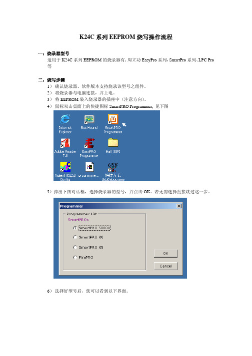
4)鼠标双击桌面上的快捷图标SmartPRO Programmer, 见下图5)弹出下图对话框,选择烧录器的型号,并点击OK。
若无需选择直接跳过这一步。
6)选择好型号后,您可以看到以下界面。
7)“芯片”菜单,点击“选择芯片”,或在快捷工具栏中点击“选择”。
见下图参见下图红色标记处。
9)打开“选项”菜单,点击“系统设置”,或点击快捷工具栏内的“设置”,参见下图10)在设置对话框内选中所需设置,点击“确定”。
11)点击“编辑”菜单,选择“编辑缓冲区”或“填充缓冲区”,或点击“打开”菜单其中:“编辑缓冲区”您可以进行所有字节编辑,填写您所需数据。
光标停留处可以通过键盘输入。
“填充缓冲区”您可以对所有字节进行编辑,但填充的数据是单一的。
当然您可以通过“打开”文件菜单,导入您所需要的hex文件。
12)若您对每个芯片设置不同的ID,可以点击“芯片”菜单,选择“芯片编号”13)在“芯片编号”对话框中填写您要设定的不同ID的地址段,变化量(自增步长),初始值,自增方式。
例如,我要求每个芯片除了00000040h---00000045h的数据不同,其余地址数据都相同,那么在“自增首址”中填入00000040h,“自增末址”中填入00000045h,自增步长为“1”,初始文件为“00”。
既第一个芯片的00000040h的数据为00,第二个芯片的00000040h的数据为01,其余数据都相同。
14)点击快捷工具栏的“编程”,开始烧录数据。
见下图,若您进行了第12、13步的操作,请在“芯片编号自增”栏打勾。
15)编程结束后,您可以选择“校验”,对烧录好的数据进行对比是否出错。
分析仪的操作方法
分析仪的操作方法
分析仪的操作方法如下:
1. 准备工作:将分析仪与电源连接,并确保电源已接通。
同时,检查仪器是否处于正常工作状态,如指示灯是否亮起。
2. 样品准备:将待分析的样品按照仪器的要求进行处理和准备。
可以将样品置于特定容器中,并确保样品的数量和质量符合仪器的要求。
3. 样品处理:根据分析的需要,在样品中添加适当的试剂或溶剂,以便在分析过程中达到最佳效果。
4. 获取数据:将样品置于分析仪的检测区域,并启动仪器开始分析过程。
根据仪器的不同,可能需要根据提示将样品放置于指定位置或调整仪器的一些参数。
5. 分析过程:仪器会自动对样品进行分析,并根据样品的性质和要求测量不同的参数。
在这个过程中,可以持续观察仪器显示屏上的数据变化。
6. 数据处理:一旦分析完成,仪器会生成分析结果。
可以根据需要对这些结果进行统计、计算或其他的处理操作。
7. 故障排除:如果在操作过程中出现异常情况,如仪器故障或数据不准确等问
题,可以参考仪器的说明书或向仪器厂商咨询,以排除故障并获得准确的分析结果。
8. 清洁和维护:在操作完成后,需要对仪器进行清洁,以确保下次使用的准确性和可靠性。
此外,定期维护和保养仪器也是十分重要的,可以延长仪器的使用寿命。
需要注意的是,不同的分析仪器因其不同的测量原理和功能特点,其操作方法和步骤可能会有所不同。
因此,在使用任何分析仪器之前,应详细阅读仪器的操作手册并遵循生产厂家提供的指导。
汽车仪表EEPROM编程器说明书
汽车仪表E2PROM编程器南京汽车仪表厂一.概述根据以前我厂NNPR仪表、重卡仪表和IVECO单表速比烧录过程中存在的一些如不能满足到汽车装备现场操作、单片机与微机数据烧录转换速率不匹配以及操作工人很容易发生误操作等问题,特开发手提式汽车仪表EEPROM编程器。
它具有以下特点和功能:(1)手体式EEPROM编程器是不需要使用PC机,只需使用单片机控制系统,就可以对汽车仪表上的EEPROM通过I2C总线数据传输方式进行读写,方便快捷,成本低廉。
(2)手提式EEPROM编程器可以满足到汽车装备现场操作的要求。
(3)手提式EEPROM编程器完全可以满足任意改写汽车仪表速比,里程公里数小计和累计的读和清零要求。
(4)手提式EEPROM编程器是一个完整的单片机控制系统,对不同表型EEPROM的操作,只需将拨码开关拨到相应的速比数,接上相应的配套束线即可。
无需在外接其它配套电源和PC机。
(5)本系统具有自保护功能,当选择表型的档位与实际要烧录的仪表型号不同而进行烧录时,系统将报警以提醒操作有误。
有效杜绝了误操作。
二.技术参数1:该编程器的工作电压为:AC220V,保险丝规格为:2A。
2:对外提供5V、12V、28V直流电压。
3:转速表、里程表速比显示4位,读写操作时第2-5位显示;累计公里数显示6或7位(其中单表显示为6位),小计公里数后4位显示,精度为0.1。
4:工作电压可切换,为12V或28V,三.操作说明1.打开电源开关,系统进入初始化,四组数码管显示全零,蜂鸣器、读成功指示灯和写成功指示灯都工作一会,以示正常。
2.如果选择开关选中某一表型,转速表速比、里程表公里脉冲数数码管的后四位分别显示拨码开关上的示数,其他两组数码管则熄灭;如果选择开关没选中任一表型,则四组数码管一直闪动显示全零,以提醒操作者先选好表型。
3.选种表型后,用相应的线束插在仪表电路板的烧录口上,即可对该种表型进行烧录。
4.在拨码开关上调到要写入的速比数。
EEPROMI2C操作说明
I2C协议2条双向串行线,一条数据线SDA,一条时钟线SCL。
SDA传输数据是大端传输,每次传输8bit,即一字节。
支持多主控(multimastering),任何时间点只能有一个主控。
总线上每个设备都有自己的一个addr,共7个bit,广播地址全0.系统中可能有多个同种芯片,为此addr分为固定部分和可编程部份,细节视芯片而定,看datasheet。
1.1 I2C位传输数据传输:SCL为高电平时,SDA线若保持稳定,那么SDA上是在传输数据bit;若SDA发生跳变,则用来表示一个会话的开始或结束(后面讲)数据改变:SCL为低电平时,SDA线才能改变传输的bit1.2 I2C开始和结束信号开始信号:SCL为高电平时,SDA由高电平向低电平跳变,开始传送数据。
结束信号:SCL为高电平时,SDA由低电平向高电平跳变,结束传送数据。
1.3 I2C应答信号Master每发送完8bit数据后等待Slave的ACK。
即在第9个clock,若从IC发ACK,SDA会被拉低。
若没有ACK,SDA会被置高,这会引起Master发生RESTART或STOP流程,如下所示:1.4 I2C写流程写寄存器的标准流程为:1. Master发起START2. Master发送I2C addr(7bit)和w操作0(1bit),等待ACK3. Slave发送ACK4. Master发送reg addr(8bit),等待ACK5. Slave发送ACK6. Master发送data(8bit),即要写入寄存器中的数据,等待ACK7. Slave发送ACK8. 第6步和第7步可以重复多次,即顺序写多个寄存器9. Master发起STOP写一个寄存器写多个寄存器1.5 I2C读流程读寄存器的标准流程为:1. Master发送I2C addr(7bit)和w操作1(1bit),等待ACK2. Slave发送ACK3. Master发送reg addr(8bit),等待ACK4. Slave发送ACK5. Master发起START6. Master发送I2C addr(7bit)和r操作1(1bit),等待ACK7. Slave发送ACK8. Slave发送data(8bit),即寄存器里的值9. Master发送ACK10. 第8步和第9步可以重复多次,即顺序读多个寄存器读一个寄存器读多个寄存器1.前言对于大多数工程师而言,I2C永远是一个头疼的问题。
分析仪操作原理及其操作方法
分析仪操作及原理注意:1、标定前请确认标气背景气、标定气含量,保证通入仪器的是对应的标气。
2、百分含量仪器通入标气后需稳定10分钟以上方可标定,微量仪器需稳定时间更长一些,待数值稳定以后再进行标定。
CO2红外气体分析仪(AIA1203)这台仪器为ABB生产EL2020系列型号为Uras26,测量范围0~5~20ppm.vol.CO2,精度为±1%一、测量原理(红外式)根据不同组分气体对不同波长的红外线具有选择性吸收的特性而工作的分析仪表。
测量这种吸收光谱可判别出气体的种类;测量吸收强度可确定被测气体的浓度。
各种多原子气体(CO,CO2,CH4等)对红外线某一段电磁波的辐射都能具有一定的吸收能力,而且这种吸收能力对波长具有选择性,只有当红外光谱中某一段光谱的频率与物质分子本身的频率一致时,该物质分子才吸收这一段红外光谱的辐射能。
我们把能吸收的这一段红外线光谱称为该气体的特征吸收波段。
气体吸收了红外线光谱的辐射能后,一部分可转变成热能,使温度升高。
红外线光谱的辐射又特别显著,这就能让我们利用各种元件,如热电堆、热敏电阻等去测量红外线辐射能的大小。
二、标定1、选择校准菜单:menu calibrate manual calibration.2、用箭头键选择zero gas。
3、接通零点气。
操作零点气钢瓶减压阀组件,使输出压力控制在20kpa,将操作面板上多通阀(5MV)切向―零点气‖,打开测量流量计,调整―测量‖转子流量计旋钮,使进气量控制在30L/H左右。
4、确认零点气连接上并且零点气浓度值输入后。
按ENTER键确认。
5、当测量示值显示稳定,按ENTER键开始校准零点。
6、接受校准结果按ENTER键;不接受校准结果返回步骤6按BACK键;不接受校准结果返回测量状态按MEAS键。
7、用箭头键选择SPAN GAS(零点标定完成后会自动跳到zero 和span的选择窗口。
8、按4步骤接通量程气。