光欣电子PDF规格书91-21SUGC-S400-A4-TR10
S400Ed-B3-Ma-061130-001用户手册说明书

127178CONTENTSPRODUCT FEATURES ACOUSTIC CHARTS INSTALLATION DIMENSIONS SPECIFICATION LIMITED WARRANTY□□□□□□□2-way 3-transducer full range plastic speakerComprising double 4" high sensitivity, big power pro woofers.One 25mm silk soft dome tweeter 120° x 120° dispersion Single-amp. modeSuits venues like supermarket or coffee house for background music application. Also canbe used in conference room or for personal multi-media purpose as a monitor.Special mounting bracket is designed for convenient min. 10°splay angle adjustment of the cabinet vertically.PRODUCT FEATURESSPECIFICATIONTransducersFrequency Response(-3dB)Dispersion(H ×V)Sensitivity(1m/1W)Crossover Point Power(RMS)Rated Impedance DC Impedance THDInput Connectors Net Weight Gross Weight Dimensions (W ×D ×H)Packing Dimensions(W ×D ×H)Power(Program)Power(Peak)SPL(1m)Max.SPL(1m)LF: 4"×2HF: 1'’×180Hz-20kHz92dB 3kHz 80W 4Ω3.6Ω<3%4.5kg 5.5kg120 ×1201×NL4111dB 117dB 160W 320W 182×182×320mm 230×230×375mm1 0 0dBS1809 01088 0 367 0 - 366 0 - 1085 0- 180501002005001k 2k 5k 10k 20k 20Hz1 4 0Deg 1 1 08 05 02 0- 1 0501002005001k 2k 5k 10k 20k 20Hz2 5 2D e g1 4 43 6- 7 2- 1 8- 2 8D e gFREQUENCY RESPONSEFREQUENCY RESPONSE20 Hz 501002005001K 2K 5K 10K20K Ohm345678910203040506070 Deg-180-150-120-90-60-300306090120150180Ohm345678910203040506070 Deg-180-150-120-90-60-300306090120150180HF IMPEDANCELF IMPEDANCE0- 10- 15- 20- 25dB 2 0050 01K2K5K1 0K2 0K 1 50 Hz01.53.04.5- 5ms100.0dBSPL90.080.070.050.060.018010836- 36- 108- 180D e gTHDWATERFALL100Hz160Hz200Hz400Hz630Hz1.0kHz1.6kHz3.15kHz6.3kHz 10kHz 16kHz2.5kHz0°30°60°90°120°150°180°210°240°270°300°330°0°30°60°90°120°150°180°210°240°270°300°330°0°30°60°90°120°150°180°210°240°270°300°330°0°30°60°90°120°150°180°210°240°270°300°330°0°30°60°90°120°150°180°210°240°270°300°330°0°30°60°90°120°150°180°210°240°270°300°330°0°30°60°90°120°150°180°210°240°270°300°330°0°30°60°90°120°150°180°210°240°270°300°330°0°30°60°90°120°150°180°210°240°270°300°330°0°30°60°90°120°150°180°210°240°270°300°330°0°30°60°90°120°150°180°210°240°270°300°330°0°30°60°90°120°150°180°210°240°270°300°330°HORIZONTAL DIRECTIVITYThe data of S400 horizontal directivity were collected by testing the speaker system in a big anechoic chamber.100Hz160Hz200Hz400Hz630Hz1.0kHz1.6kHz3.15kHz6.3kHz 10kHz 16kHz2.5kHz0°30°60°90°120°150°180°210°240°270°300°330°0°30°60°90°120°150°180°210°240°270°300°330°0°30°60°90°120°150°180°210°240°270°300°330°0°30°60°90°120°150°180°210°240°270°300°330°0°30°60°90°120°150°180°210°240°270°300°330°0°30°60°90°120°150°180°210°240°270°300°330°0°30°60°90°120°150°180°210°240°270°300°330°0°30°60°90°120°150°180°210°240°270°300°330°0°30°60°90°120°150°180°210°240°270°300°330°0°30°60°90°120°150°180°210°240°270°300°330°0°30°60°90°120°150°180°210°240°270°300°330°0°30°60°90°120°150°180°210°240°270°300°330°The data of S400 vertical directivity were collected by testing the speaker system in a big anechoic chamber.VERTICAL DIRECTIVITY182mm320m m182mmINSTALLATIONDIMENSIONSTop viewFront view吊装吊装平放50mm50m mLIMITED WARRANTYIf malfunction occurs during the specified warranty period from the date of original purchase,the product will be repaired or replaced without charge by Elder Audio.The Limited Warranty does not apply to:(a)exterior finish or appearance;(b)certain specific items described in the individual product data sheet or owner's manual;(c)malfunction resulting from use or operation of the product other than as specified in theindividual product data sheet or owner's manual;(d)malfunction resulting from misuse or abuse of the product;(e)malfunction occurring at any time after repairs have been made to the product by anyoneother than Elder Audio Service or any of its authorized service representatives.To obtain warranty service, customer must deliver proof of purchase of the product in the formof a bill of sale or receipt invoice.S400 Speakers and Speaker Systems are guaranteed against malfunction due to defects in materials or workmanship for a period of three (3) years from the date of original purchase. The Limited Warranty does not apply to burned voice coils or malfunctions such as cone and/or coil damage resulting from improperly designed enclosures. Additional details are included in the Limited Warranty statement.S400 Accessories are guaranteed against malfunction due to defects in materials or workmanship for a period of one (1) year from the date of original purchase. Additional details are included in the Limited Warranty statement.S400 Flying Hardware (including enclosure-mounted hardware and rigging accessories) is guaranteed against malfunction due to defects in materials or workmanship for a period of one (1) year from the date of original purchase. Additional details are included in the Limited Warranty statement.Specifications are subject to change without notice.。
CITIZEN 电子 CITISENSOR PR-40-T 光电传感器规格说明书

9. Precautions 9-1. Soldering(1) Manual Soldering1) Solder with silver content is recommended.2) As to CITISENSORs that have absorbed moisture by any chance, baking isrecommended prior or the soldering process to prevent CITISENSORs from the possible crack problem due to the absorbed moisture.3) The use of the soldering iron in less than 25W and the temperature of iron tip must be kept at no higher than 350°C.4) Force or stress must not be applied to the resin portion while soldering. 5) It is requested to solder each land within 3 seconds.6) It is requested that products should be handled after their temperature has dropped down to the normal room temperature.(2) Reflow soldering1) Following soldering paste is recommended Melting temperature: 178 ~ 192°C. Composition: Sn 63 %, Pb 37 %2) The temperature profile at the top surface of the parts is recommended as shown below.3) It is requested that products should be handled after their temperature has dropped down to the normal room temperature.(3) Lead free soldering1) Following soldering paste is recommended Melting temperature: 216 ~ 220°C.Composition: Sn 3.5Ag 0.75Cu2) The temperature profile at the top surface of the parts is recommended as shown below.3) It is requested that products should be handled after their temperature has dropped down to the normal room temperature.Reflow soldering of the above profile is allowed two times.ApprovedCheckedDrawnSymbol CITISENSORNamePR-40140~160°C4°C sec.Max10sec.Max240°C Max More than 1min.T e m p e r a t u r eTime4°C /sec.Max140sec160~180°C4°C /sec.MaxT e m p e r a t u r eTime4°C /sec.Max260°C Max 220°C60~70secReferenceAug.22,2007M.Okuwaki9-2. CleaningPerform the cleaning after soldering strictly in conformity to the following conditions:· Cleaning Agent : Alcohol· Temperature and Time: 30 seconds under the temperature below 50°C or 3 minutes below 30°C.· Ultrasonic Cleaning : 300W or less9-3. Other Precaution1) It is requested to avoid any stress added to the resin portion while heating.2) It is requested to avoid any friction by sharp metal nail etc. to the resin portion. 10. Precautions on Designing1) The Current limiting Resistor should be placed on the circuit to drive within the rating. Also the design should be done to avoid the reverse voltage (over-current) applied instantaneously when turned ON or OFF .2) When the Pulse Driving Current is applied, the average current consumptionshould be within the rating. Also the design should be done to avoid the reverse voltage applied when put off.3) Recommended Soldering Pattern<For Reflow Soldering>The above dimensions are recommended,but the mountability study should be conducted in advance at your site.4) When assembling the circuit board into the finished products, pay attention to avoid the component parts from touching with other parts.ApprovedChecked DrawnSymbol CITISENSORNamePR-40ReferenceAug.22,2007M.Okuwaki0.60.60.60.60.30.375。
WiebeTech FRTX400H-QJ 用户手册说明书

FRTX400H-QJ™USER’S MANUALRevised December 30, 2008Thank you for purchasing WiebeTech’s FRTX400H-QJ. FRTX400H-QJ features WiebeTech’s write-blocked technology, quadruple connectivity for each bay, and power/access LEDs all inside of a tough, durable aluminum frame and lid. Whether in the field or in a lab FRTX400H-QJ is a must-have for forensic investigators.Features•TrayFree™ technology! Simply slide in a SATA drive and shut the door. Each SATA bay offers a lock for additional security, and shock protection for longer drive life. All metal bays.•Copy data from IDE or SATA drives. Bays one (PATA) and three (SATA) are write-blocked. Bays two and four (SATA) are read/write making it possible to write to SATA drives from the write-blocked drives.•Quadruple connectivity. FRTX400H-QJ comes with all the cables you need to connect to eSATA, FireWire 800, FireWire 400 and USB.•Each hard drive has its own data channel for maximum speed.•Power and access LEDs let you know status of your hard drives.•Sturdy aluminum case provides excellent heat dissipation and rugged durability.•Heavy duty handle allows for easy transport.Table of Contents1. Pre-Installation Steps 3 1.1 FRTX400H-QJ Accessories 31.2 Identifying Parts 32. Using FRTX400H-QJ 4 2.1 Installing a Host Bus Adapter (HBA) 4 2.2 Jumper Configuration for3.5-inch IDE/PATA HDD 4 2.3 Installing Hard Drives 42.3.1 SATA HDD: 3.5-inch 42.3.2 IDE/PATA HDD: 3.5-inch 52.3.3 SATA HDD: 2.5-inch 6 2.4 FRTX400H-QJ Host Connections 7 2.5 Connecting FRTX400H-QJ to your Computer 72.6 Daisy Chaining 73. Usage with Mac and Windows Operating Systems 7 3.1 Usage with Macintosh Computers 73.1.1 Compatibility 73.1.2 Using Volumes 7 3.2 Usage with Windows Operating System 83.2.1 Compatibility 83.2.2 Using Volumes 84. Frequently Asked Questions 85. Technical Specifications 9Forensic Device User AdvisoryWe recommend that you perform a final check on this product.Prior to first use, please verify that the write-blocking function of this product is working properly. This is easily done: attach a known good formatted drive, and verify that the drive mounts properly on your computer. Use a drive that has data on it that you are willing to overwrite. Transfer files to the drive. The files will appear to transfer to the drive. Thereafter, unmount the drive and remount the drive. The files that you wrote to the drive should not appear after the drive is remounted. If they do appear, there is a problem with your Forensic Device, and you should contact our support department immediately for further instructions.1. Pre-Installation Steps1.1 FRTX400H-QJ AccessoriesCheck the accessories with your FRTX400H-QJ. Please contact WiebeTech if any parts are missing or damaged. The box should contain the following items:1.2 Identifying PartsTake a moment to familiarize yourself with the parts of the FRTX400H-QJ. This will help you to better understand the remaining instructions.Accessories QuantityFRTX400H-QJ unit 1 2.5-inch SATA HDD holster 1 eSATA to eSATA cable 4 FireWire 800 to 800 cable 4 FireWire 800 to 400 cable 4 USB cable 4 Power cord1 Packet of screws and keys1 Manual and Warranty Information(on CD)WARNING: Do not block the ventilation fan during operation. Overheating may damage the device or the hard drives.Bays one and three are write-blocked Bays two and four are read/write Front View Key lock Ejection handleHandle Key lock Rear View 8cm Fan Power ConnectionPower Switch FireWire Ports Power Supply Fan USB Port eSATA Port2. Using FRTX400H-QJ2.1 Installing a Host Bus Adapter (HBA)(Optional) Install a host bus adapter (HBA) with FireWire 800 or eSATA ports into an empty expansion slot inside your computer. If your computer already has available FireWire or eSATA ports, or if you would rather use USB, you can skip this step. Compatible cards are available from WiebeTech (). The following general steps will work for most cards. Instructions for individual cards may vary, so consult your card’s user manual.a) Power down the computer system.b) Insert the PCI card into an available PCI slot. Do not force it, but it will take firm pressure to fullyseat the interface. It may help to gently rock the card back and forth as you apply pressure. c) Once the card is fully seated in the slot, secure it in place with a screw. d) Turn the computer back on.2.2 Jumper Configuration for3.5-inch IDE/PATA HDDIf using a 3.5-inch IDE/PATA drive configure the jumpers on your hard drive. The drive must be set to the Master setting. Consult the instructions for your drive (some drives display configuration information on the drive’s label). A few drives have both “Master with Slave Present” and “Master without Slave” options. Choose the latter in this case. In rare cases, if the Master setting does not work then try Cable Select.2.3 Installing Hard Drives2.3.2 SATA HDD: 3.5-inchFor SATA drives simply pull on the ejection handle and open the door. Then just slide in your SATA drive and shut the door behind it. The drive slides in with the label up and the SATA connection on the drive isthe side that slides in first. For extra security for yourharddrive you can lockthe bay, butmake sure tounlock it before pulling on the ejection handle again.IDE interfaceJumper PinsPower Rear of hard drive (Example)2.3.1 IDE/PATA HDD: 3.5-inchFor IDE/PATA drives, pull gently on the handle to slide the tray out. If the tray doesn’t slide out easily, do not continue to pull on the handle. Check the lock and make sure that the tray is unlocked.Once the tray is out, remove the tray’s top and bottom coverings with the leverage key. Attach your IDE/PATA drive to the ribbon cable and to the 4-pin power cable.Put the drive into the tray and secure it with screws. Set the top and bottom coverings back onto the tray and put the tray back into the bay of the FRTX. Lock the tray—the tray will notpowerif left in the unlocked position—and then move on to the next step.Leverage Key2.3.3 SATA HDD: 2.5-inchOpen up one of the SATA bays. Slide the 3.5-inch to 2.5-inch converter in with the SATA connection towards the back and the black grilled top facing up as the picture below shows.Place the 2.5-inch SATA HDD into the drive slot located on the front of the 3.5-inch to 2.5-inch converter.When the 2.5-inch drive makes it’s connection inside of the 3.5-inch to 2.5-inch converter then you can push the converter all the way inside the TrayFree bay. To uninstall the converter and drive simply pull on the ejection handle on the TrayFree bay and push the eject button on the 3.5-inch to 2.5-inch converter. The 2.5-inch SATA drive should eject slightly, justbecautiousandhold the converter horizontal when ejecting a 2.5-inch drive.Eject Button(Mac)2.4 FRTX400H-QJ Host ConnectionsConnect the eSATA, FireWire or USB cable from your computer into the port on the FRTX400H-QJ.2.5 Connecting FRTX400H-QJ to your ComputerPlug in the data cables and power cord. The FRTX400H-QJ connects to your computer through FireWire, eSATA or USB. Each drive has its own dedicated connection for maximal data speeds. Plug one end of each cable to the back of the unit. Insert the other end into an open port on the computer.2.6 Daisy ChainingIf daisy-chaining, join all four bays together using three FireWire cables. Connect a fourth FireWire cable to one of the remaining open FireWire ports on the back of the FRTX. Plug the other end of that cable into an open FireWire port on the computer. Be sure to label your drives in such a way that you’ll know which one you’re accessing on the computer.Your product is now ready to use! Turn on the power switch on the back of the unit. If your target drives are already formatted, you can begin using them right away. Otherwise you can format them at this time to prepare them for usage with your computer. For obvious reasons, drives in the write-blocked bays cannot be formatted.3. Usage with Mac and Windows Operating Systems3.1 Usage with Macintosh Computers3.1.1 CompatibilityThe FRTX400H-QJ is Plug-and-Play compatible under OS X. No drivers are needed. The USB2 port is USB 1.1 compatible.3.1.2 Using VolumesIf the hard drive attached to the FRTX400H-QJ is already formatted, an icon representing the drive’s volume will appear (mount) onthe desktop. You can begin using the volume right away. If the drive is unformatted and you are using a write-blocked bay, try moving to a Windows based OS for usage. If you are using a read/write bayamessage will appear on the desktop saying that thedisk isunreadable. You can use OS X’s Disk Utility to easily format the drive.eSATA USB FireWire 800 FireWire cables(Windows XP)Eject the volume before powering down the unit by dragging the volume’s icon to the trash bin, or by selecting the volume then pressing Command-E. Shutting down the unit without first ejecting the volume can result in data loss.3.2 Usage with Windows Operating System3.2.1 CompatibilityThe FRTX400H-QJ is Plug-and-Play compatible with Windows XP and Vista. No drivers are needed on this operating system. The USB2 port is USB 1.1 compatible.3.2.2 Using VolumesIf the hard drive attached to the FRTX is already formatted, you can begin using the volume right away. If the drive is unformatted and you are using a write-blocked bay, try moving to a Mac based OS for usage. If you are using a read/write bay a message will appear on the desktop saying that the disk is unreadable. If no window appears, you can find the volume by right-clicking the “My Computer” icon and going to “Manage.” When “Computer Management” appears you can select “Disk Management” to begin formatting your volume as NTFS.Eject the volume before powering down the unit by single-clicking the green arrow icon on the task bar, then selecting “Safely remove….” Windows will indicate whenit is safe to disconnect the dock. Shutting down the unit without first ejecting thevolume can result in data loss.4. Frequently Asked QuestionsQ: I've attached my RTX400-QR and can see the volume, but it shows up twice. Which one is the realvolume?A: If you are seeing your RTX400-QR volume mounted twice, chances are the unit is connected to the computer using both the eSATA and FireWire connections. When this is the case, the OS may attempt to mount the RTX twice resulting in two volumes appearing. Simply turn off the RTX and unplug one of the connections to resolve the problem.Q: Why won't the computer let me eject or unmount my drive?A: There may be a software application running in the background with an active link to the drive. Sometimes, you may see a message such as "The disk is in use and could not be ejected. Try quitting applications and try again."It could be a background application like Sherlock or the Finder. This is not a defect or issue caused by the WiebeTech device. Try invoking the Force Quit feature in OS X to see what software may be running. For Windows XP, the equivalent command is CTRL-SHIFT-ESC.Drives connected to the computer via eSATA cannot be ejected in Windows the way FireWire drives can. However, freeware utilities are available on the internet that provide a similar function.Q: Why does my eSATA device appear as a Parallel SCSI device in System Profiler?A: The "Serial ATA" tab in System Profile shows devices attached to the internal SATA bus, but not always devices attached to an eSATA host card. Sometimes these devices will appear under the heading "Parallel SCSI" instead. This is entirely normal and does not indicate a problem with the device or its drivers.5. Technical SpecificationsProduct name/code: FRTX400H-QJ (35440-2509-0000)Host Interfaces: eSATA: up to 3 Gbps (95MB/s approximate actual speed)Dual FireWire 800: up to 800 Mbps (55MB/s approximate actual speed) USB 2.0: up to 480 Mbps (30MB/s approximate actual speed)Drive Types Supported: Bay One: 3.5″ IDE/PATA hard drive up to 750GB. Write-blocked.Bay Two: 3.5” SATA 1 or SATA 2 hard drives up to 1TB. Read/Write. Bay Three: 3.5” SATA 1 or SATA 2 hard drives up to 1TB. Write-blocked. Bay Four: 3.5” SATA 1 or SATA 2 hard drives up to 1TB. Read/Write.Bridges All bridges are Oxford 934DSB TrayFree™ Technology: Yes, with bays two, three and four Shock Absorbing Bays: Yes, with bays two, three and four Lockable Bays: Yes, on all baysPower LED: Yes, on all baysAccess LED: Yes, on all baysOperating System Requirements: Windows XP and VistaMac OS XLinux distributions using Kernel version 2.4 or above (USB only)Operating Temperature: 50 – 85° Fahrenheit (10 – 30° Celsius) Operating Humidity: 5% to 95%, noncondensingPower Switch: 2 position: On / OffPower Supply: Input: 100-240VAC Output: 220 WattsCooling Fan: 8cm Ball Bearing FanExternal Material: Aluminum alloy caseShipping Weights: 16 lbs sans drivesFRTX400H-QR Weight: 14 lbs sans drivesDimensions: (177mm W x 270mm D x 231mm H)Warranty: 2-year limited warranty. See warranty statement for details and limitations. WiebeTech offers free phone support for 90 days after purchase (1-866-744-8722). After 90 days, email support is available at *********************.FRTX400H-QJ, RTX and TrayFree are trademarks of CRU-DataPort. Other marks are the property of their respective owners.© 2008 CRU-DataPort. All rights reserved.If you have any questions or problems, please contact *********************for technical support. If you are interested in purchasing more WiebeTech products, check our website or contact *******************. We appreciate being able to serve you!。
4路通用调光器SDK-U4-10(EIB)操作手册说明书
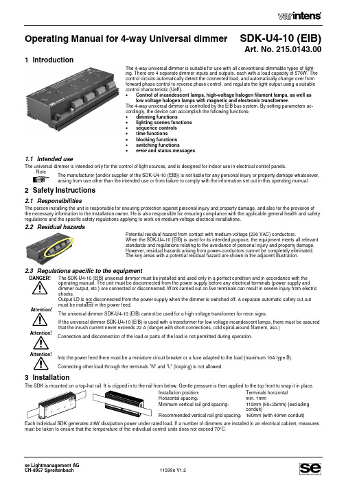
Operating Manual for 4-way Universal dimmer SDK-U4-10 (EIB)Art. No. 215.0143.001 IntroductionThe 4-way universal dimmer is suitable for use with all conventional dimmable types of light-ing. There are 4 separate dimmer inputs and outputs, each with a load capacity of 570W. The control circuits automatically detect the connected load, and automatically change over from forward phase control to reverse phase control, and regulate the light output using a suitable control characteristic (Ueff). • Control of incandescent lamps, high-voltage halogen filament lamps, as well aslow voltage halogen lamps with magnetic and electronic transformer.The 4-way universal dimmer is controlled by the EIB bus system. By setting parameters ac-cordingly, the device can accomplish the following functions: • dimming functions • lighting scenes functions • sequence controls • time functions • blocking functions • switching functions • error and status messages1.1 Intended useThe universal dimmer is intended only for the control of light sources, and is designed for indoor use in electrical control panels.The manufacturer (and/or supplier of the SDK-U4-10 (EIB)) is not liable for any personal injury or property damage whatsoever, arising from use other than the intended use or from failure to comply with the information set out in this operating manual. Instructions2.1 ResponsibilitiesThe person installing the unit is responsible for ensuring protection against personal injury and property damage, and also for the provision ofthe necessary information to the installation owner. He is also responsible for ensuring compliance with the applicable general health and safety regulations and the specific safety regulations applying to work on medium-voltage electrical installations.2.2 ResidualhazardsPotential residual hazard from contact with medium-voltage (230 VAC) conductors.When the SDK-U4-10 (EIB) is used for its intended purpose, the equipment meets all relevant standards and regulations relating to the avoidance of personal injury and property damage. However, residual hazards arising from power-conductors cannot be completely eliminated. The key areas with a potential residual hazard are shown in the adjacent illustration.2.3 Regulations specific to the equipmentDANGER!The SDK-U4-10 (EIB) universal dimmer must be installed and used only in a perfect condition and in accordance with the operating manual. The unit must be disconnected from the power supply before any electrical terminals (power supply and dimmer output, etc.) are connected or disconnected. Work carried out on live terminals can result in severe injury from electric shocks.Output LD is not disconnected from the power supply when the dimmer is switched off. A separate automatic safety cut-out must be installed in the power feed.The universal dimmer SDK-U4-10 (EIB) cannot be used for a high voltage transformer for neon signs.If the universal dimmer SDK-U4-10 (EIB) is used with a transformer for low voltage incandescent lamps, there must be assured that the inrush current never exceeds 22 A (danger with short connections, cold spiral-wound filament, aso.) Attention!Connection and disconnection of the load or parts of the load is not permitted during operation.Into the power feed there must be a miniature circuit breaker or a fuse adapted to the load (maximum 10A type B). Connecting other load through the terminals "N" and "L" (looping) is not allowed.3 InstallationThe SDK is mounted on a top-hat rail. It is clipped in to the rail from below. Gentle pressure is then applied to the top front to snap it in place.Installation position: Terminals horizontal Horizontal spacing:min. 1mmMinimum vertical rail grid spacing:115mm (90+25mm) (excluding conduit)Recommended vertical rail grid spacing: 160mm (with 40mm conduit)Each individual SDK generates 23W dissipation power under rated load. If a number of dimmers are installed in an electrical cabinet, measures must be taken to ensure that the temperature of the individual control units does not exceed 70°C.SDK-U4-10 (EIB) Operating Manual 24 Control ModesThe SDK is controlled by a EIB standard bus.The following illustrations show the connections used and the required settings.4.1 Connection of the EIB busThe EIB bus contains power supply (24V) as well as the bus signal (tele-gram) in a 2wire twisted pair cable.Connect the EIB bus to the two plug-in terminals marked "BUS". Connect the negative polarity to the black and the positive to the red plug-in termi-nal.4.2 Operating ParametersThe system programmer can set the following parameters for each channel: • Operating mode (each channel separately or two parallel) • Switching functions • Time functions • Lighting scenes functions • Sequence control • Blocking functions • Operating and error status4.3 CommissioningWhen delivered, the SDK-U4-10 (EIB) has no device and group addresses.The needed functions can be activated in the parameter setting. During project management with the ETS software only the activated objects will be visible.Important:Due to the built in bus coupler (BCU 2.1) the following measures must be taken before commissioning the device: for ETS 2.0 V1.2 / 1.3 and for ETS 3.0- service packs and all patches must be installed - product data base must not be older than 09/2005The application program must always be completely copied into the device. Partial copies lead to malfunctioning.For announcing the device to the system, press the "PROG"-button with a small screwdriver. The red LED will light up during the transmission.3SDK-U4-10 (EIB) Operating Manual5 LoadCircuitThe 4-way universal dimmer is capable ofcontrolling 230V incandescent lamps, low voltage halogen lamps with electronic or magnetic transformers up to a maximum current of 2.5 A (570 W). The dimmed voltage is present at output "LD". The universal dim-mer uses transistor circuitry to control the output voltage.Mixed load (inductive and capacitive) on one output are not allowed!From one channel to the next channel on the same dimmer the connections "N" and "L" may be looped (two terminals per connection). It is not allowed to connect another device through these terminals.Test function:Each circuit can be individually tested bypressing the relevant "TEST"-key on the power section. One press of the key switches the circuit on. A second, long press activates dimming, while a third press reverses the dimming into brightening. To switch off, it is necessary to interrupt the power supply (safety cut-out). A value generated with the test-key is overwritten if another value is demanded from the EIB bus (and vice versa).INCANDESCENT LAMPLOW-VOLTAGE-HALOGENLAMP5.1 Parallel power connectionTo increase the power, two dimming circuits ( A+B and C+D ) can be software-connected in parallel ( 2 x 570W = 1140W ). • The circuits connected together must be in the same phase. • On the power section, the contacts of the common dimming circuits must be connected together (L with L, N with N and LD with LD). • The parallel connection must be software-programmed.6 LED Indicators on the DimmerThe dimmer has 1 LED on the interface section and 4 LEDs on the power section:Interface section: Red LED ON During pressing the programming button the LED is on. OFF Unit is operating normally or supply is not connected. Power section:Green LED 1–4 ON Dimming circuit on (over the EIB bus or the "Test" keys). OFF Dimming circuit off.7 Fault Finding and EliminationFaultRemedyLamp does not brighten.The relevant lighting circuit can be dimmed or brightened by pressing one of the keys on the power sec-tion, after removing the bus cable. If the circuits do not respond, check the load circuit wiring.Check the bus voltage on the SDK (red LED must come on while pressing the programming button).SDK-U4-10 (EIB) Operating Manual 4 8 Technical DataTypeArticle number Mechanical data:SDK-U4-10 (EIB) 215.0143.00Case: Steel sheet with aluminium coolerDimensions: Width:216.5mmHeight: 90 mmDepth: 44 mm (from top-hat pr.)Weight: 850gInstallation: On DIN top-hat profile rails 35 mmMains power connection: 4 plug-in terminals max. 2.5 mm²Load connection: 1 plug-in terminal max. 2.5 mm²Control connections:Ambient conditions:2 plug-in terminals max. 0.8 mm²Ambient temperature: ta 0-40 °C max. Do not blockairflow at cooler.Storage temperature: 70 °C max.Air humidity: 10%...80% relative air humidity,non-condensingCase temperature: tc 70 °C max.IP protection: IP20Electrical data: per channelMains voltage: 230 V ±10%Mains frequency: 50 / 60 HzPreliminary fuse: 10 A max. (type B)Dimming output technology: Transistor-driven forward phasecontrol / reverse phase controlMaximum load, dimming output: 570 W / VA (2.5A) resistive / inductive / capacitiveMinimum load, dimming output: 5 W resistiveLeakage power at rated load: 5.7 W at rated loadLeakage power on standby: 1.4 WCooling: Naturalaircirculation No-load voltage: Approx. 55 V rmsShort-circuit protection: Electronic fast cut-offOverload protection: Temperature monitoring. (triggervalue approx. 85°C)Symmetry errors: Not measurableImpulse switching flank: 100µs, rated load with inc.-lamp Operational and fault indicator: Green "Run" LED per channelKeys (integrated single-key control): On / brighter / dimmer. (for test purposes at initial start-up)Insulation: 2500 V betw. interface / dimmer Switch-on delay: approx. 1s (mains switch-on)The product data base for the SDK-U4-10 (EIB) can be found in the "download"-section on www.se-ag.ch. Control:Operational voltage: 28VDV (from EIB-Bus) Bus protocol: EIBIndications: LED (Program) red Control elements: Programming buttonCE mark:as per 89/336/EWG and 73/23/EWGEN 60669-2-1 Safety requirementsEN 55015 Interference transmission EN 55014-2 (VDE 0875) Radio interferenceEN 61000-3-2 HarmonicsWould you like more «varintens» information? Visit our web site! www.se-ag.che-mail:*************se Lightmanagement AGGüterstrasse 11, CH-8957 Spreitenbach, SwitzerlandTel. +41 56 418 76 11, Fax +41 56 401 49 86。
思捷光电 MARS-F 系列光纤式单色红外测温仪 使用说明书

MARS-F系列光纤式单色红外测温仪使用说明书常州思捷光电科技有限公司地址:江苏省常州经济开发区丁堰街道联丰路101号联谷智造中心2幢101室 E-mail:****************TEL**************FAX**************目录1.1概述 (4)1.2产品特点 (4)1.3光纤式单色红外测温仪原理 (5)1.4适用场合 (6)1.5技术参数 (6)1.5.1MARS-FS技术参数 (6)1.5.2MARS-FG技术参数 (7)1.6接线表...................................................................................................................................................................82.1安装调试...............................................................................................................................................................82.1.1安装...........................................................................................................................................................82.1.2调试.......................................................................................................................................................102.1.2.1发射率系数调整............................................................................................................102.1.2.2选择测量模式................................................................................................................142.1.2.3设置报警值(上限报警,下限报警),模拟量输出起始值,终点值等。
Cessna产品型号说明书
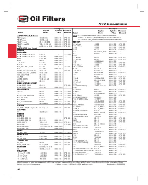
CESSNA150 A thru M O-200 CH48108-1 CFO-100-1F150 F thru M O-200 CH48108-1 CFO-100-1A150L O-200 CH48108-1 CFO-100-1FA150 O-200 CH48108-1 CFO-100-1152 O-235-L2C, H2C CH48110-1 –162 0-200-D CH48108-1 –C-172172 A thru H O-300 CH48108-1 CFO-100-1172 I thru M O-320 CH48110-1 CFO-100-1172N O-320-H2AD CH48103-1 –172P O-320-D2J CH48111-1 CFO-101-1F172 D thru H O-300 CH48108-1 CFO-100-1FR172 E thru K IO-360 CH48108-1 CFO-100-1R172K IO-360-K CH48108-1 –172R and S IO-360-L2A CH48110-1 –172RG O-360-F1A6 CH48110-1 CFO-100-1172S IO-360-L2A CH48110-1 –177 O-320 CH48110-1 CFO-100-1177A, B O-360-A1F6D CH48103-1 CFO-100-1177RG IO-360-A1B6D CH48103-1 CFO-100-1180 A thru J O-470 CH48108-1 CFO-100-1180Q O-470-U++ CH48108-1 CFO-100-1180-S/N 53087 & Up 1111O-470-U++ CH48108-1 –C-182182 A Thru P O-470 CH48108-1 CFO-100-1182Q, R O-470-U++ CH48108-1 CFO-100-1182S IO-540-AB1A5 CH48110-1 –A182 K thru N O-470 CH48108-1 CFO-100-1182-S/N 67042 & Up O-470-U++ CH48108-1 –F182-S/N 00130 & Up O-470-U++ CH48108-1 –R182 O-540-J3C5D CH48103-1 CFO-100-1T182 O-540-L3C5D CH48103-1 CFO-100-1TR182, FTR182 O-540-L3C5D CH48103-1 CFO-100-1185 A thru D IO-470, IO-520 CH48108-1 CFO-100-1A185E, F IO-470, IO-520 CH48108-1 CFO-100-1185-S/N 03852 & Up IO-520 CH48108-1 –188 O-470, IO-520 CH48108-1 CFO-100-1188-S/N 03474 & Up IO-520D CH48109-1 –T188-S/N 03474 & Up TSIO-520 CH48109-1 –205A IO-470 CH48108-1 CFO-100-1C-206 IO-540 CH48110-1 CFO-100-1206 A thru G IO-520 CH48108-1 CFO-100-1206H IO-540-AC1A5 CH48110-1 –206-S/N 05030 & Up IO-520 CH48109-1 –206-S/N 05030 & Up TSIO-520 CH48109-1 –U206 IO-520 CH48108-1 CFO-100-1T-206H TI0540-AJ1A CH48110-1 –TU-206 TSIO-520 CH48108-1 CFO-100-1P206 IO-520 CH48108-1 CFO-100-1TP206 TSIO-520 CH48108-1 CFO-100-1207 IO-520 CH48108-1 CFO-100-1207-S/N 05227 & Up IO-520 CH48109-1 –T207-S/N 05227 & Up TSIO-520 CH48109-1 –T207 TSIO-520 CH48108-1 CFO-100-1210 IO-470, IO-520 CH48108-1 CFO-100-1210-S/N 63373-63375 & Up IO-520 CH48109-1 –T210-S/N 63373-63375 & Up TSIO-520 CH48108-1 –P210-S/N 278 &Up TSIO-520 CH48108-1 –T210, P210-S/N 1-277 TSIO-520++ CH48108-1 CFO-100-1 32Aircraft engines not listed, but equipped with oil fi lters at overhaul, may accept Champion fi lters. Write Aviation Service Deptment for further information. Please include description of your engine. ++ Reference page 25-26 for other TCM application data. * Requires Lyco (54E23093) AEROSPATIABLE (SocataTB9 Tampico O-320-D2A CH48110-1 CFO-100-1TB10 Tobago O-360-A1AD CH48110-1 CFO-100-1TB20 Trinidad IO-540-C4D5D CH48103-1 CFO-100-1TB21 Trinidad TC TIO-540-AB1AD CH48103-1 CFO-100-1TB30 AEIO-540-L1B5D CH48103-1 CFO-100-1AEROSTAR (See Piper)BEECHBONANZAE33A, F33A, F33B, F33C IO-520 – CFO-100-1E33A, F33A, F33B, F33C IO-520B CH48109-1 –G-33 IO-470N CH48108-1H-35 O-470 CH48108-1 –J, K, M-35 IO 470-C CH48108-1N, P-35 IO-470-N CH48108-1S35, V35, V35A, V35B IO-520 – CFO-100-1S35 IO-520B CH48109-1 –V35TC, V35A-TC, V35B-TC TSIO-520 – CFO-100-1V35TC, V35A-TC, -V35B-TC TSIO-520D CH48109-1 –V35, V35A, V35B IO-520B CH48109-1 –36, A36 IO-520B CH48109-1 –A36TC, B36TC TSIO-520-UB CH48109-1 –B36-550 IO-550 CH48109-1 –DEBONAIR/BONANZAC33A, E33A, E33C IO-520 – CFO-100-1C33A, E33A, F33C IO-520B CH48109-1 –MUSKETEERSport III O-320 CH48110-1 CFO-100-123 O-320 CH48110-1 CFO-100-1A23-19, 19A, B19 Sport O-320 CH48110-1 CFO-100-1A23, 23, A23A IO-346 – CFO-100-1A23, A23A IO-346A CH48109-1 –B23, C23 Sundowner O-360 CH48110-1 CFO-100-1B23 O-360A4JD CH48103-1 CFO-100-1SIERRA24, A-24, A-24R, B-24R, C-24R IO-360, -L2A CH48110-1 CFO-100-1SKIPPER77 O-235-L2C CH48110-1 –BEECHBARONC55, D55, E55, 58 IO-520 – CFO-100-1C55, D55, E55, 58 IO-520C CH48109-1 –56TC, A56TC TIO-541-E CH48104-1 CFO-101-1Baron 58P TSIO-520-L++ – CFO-100-1Baron 58P, 58TC TSIO-520-L, -W, -B CH48108-1 –Baron 58C, 550 IO-550 CH48109-1 –DUKE60, A60, B60 TIO-541 CH48104-1 CFO-101-1QUEEN AIR65, 70 IGSO-480 CH48111-1 CFO-101-180, 88, B80 IGSO-540 CH48111-1 CFO-101-1TRAVEL AIR95, B95 O-360 CH48110-1 CFO-100-1B95A, D95A, E95 IO-360, L2A CH48110-1 CFO-100-1DUCHESS LO-360-A1G6D &76 O-360-A1G6D CH48103-1BELLANCA17-31A, 17-31ATC IO-540-K CH48110-1 CFO-100-117-31A Viking IO-540-K CH48110-1 CFO-100-117-31A Viking IO-520-D – CFO-100-117-31ATC Turbo TIO-540 CH48110-1 CFO-100-1ChampionEngine Spin-On ChampionModel Model Filter ElementChampionEngine Spin-On ChampionModel Model Filter ElementNOTE: A ll Cessna aircraft modifi ed under Cessna Service BulletinSEB-93-1 or MEB 93-1, require Champion Oil Filter CH48108-1.The CH48109-1 may also be used if clearance permits installation.Aircraft Engine ApplicationsCESSNA T303 LTSIO-520-AE &TSIO-520-AE CH48109-1 –310 C thru Q IO-470 CH48108-1 CFO-100-1310 RIO-520-M CH48108-1 –T310P, Q, R TSIO-520-B CH48108-1 CFO-100-1320-A TSIO-470 CH48104-1 –320-B, C TSIO-470 CH48109-1 CFO-101-1320-D TSIO-520 – CFO-100-1320-D, E, F TSIO-520-B CH48108-1 –335 TSIO-520-EB CH48109-1 –336 IO-360 CH48108-1 CFO-100-1337 IO-360 CH48108-1 CFO-100-1P337, P337H TSIO-360 CH48108-1 CFO-100-1T337H TSIO-360-H CH48108-1 CFO-100-1340 TSIO-520-K CH48108-1 –340A TSIO-520-N, -NB CH48109-1 CFO-100-1401/402TSIO-520-E CH48108-1 CFO-100-1402C TSIO-520-VB CH48109-1 CFO-100-1404GTSIO-520-M CH48111-1 CFO-101-1411-S/N 000 thru 0126 GTSIO-520-C CH48104-1 –411-S/N 0127 and up GTSIO-520-C CH48111-1 CFO-101-1414, 414A TSIO-520-J, -N CH48108-1 –421A, BGTSIO-520-D, -H, CH48111-1 CFO-101-1421C-S/N 1017 thru 1404 -L, -N, ++ CH48111-1 CFO-101-1CIRRUS AIRCRAFT SRV, SR20I0-360ES CH48108-1SR22I0-550N CH48109-1COLUMBIA/LANCAIR COLUMBIA 300, 350 I0-550N CH48109-1 CFO-100-1COLUMBIA 400 TS10-550 CH48109-1 CFO-100-1DIAMOND AIRCRAFT DA20-1C I0-240 CH48108-1 CFO-100-1DA40-180I0-360 CH48110-1 CFO-100-1GULFSTREAM AMERICAN (Single Engine Models)AA-1, 1A, 1B, 1B Trainer, TR 2/Lyco O-235 CH48110-1 CFO-100-1A1C Lynx, T-Cat Lyco O-235-L CH48110-1 CFO-100-1AA-5 Traveler Lyco O-320-E CH48110-1 CFO-100-1AA-5A Cheetah Lyco O-320-E CH48110-1 CFO-100-1AA-5B Tiger Lyco O-360-A4K CH48110-1 CFO-100-1Cougar 2/Lyco O-320-D CH48110-1 CFO-100-1COMMANDER 112, 112A IO-360-C, -L2A CH48110-1 CFO-100-1112TC TO-360-C1A6D CH48103-1 CFO-100-1114IO-540-T4A5D CH48103-1 CFO-100-1500B, 500U IO-540 CH48110-1 CFO-100-1700TIO-540-R2AD CH48103-1 CFO-100-1 33Aircraft engines not listed, but equipped with oil fi lters at overhaul, may accept Champion fi lters. Write Aviation Service Deptment for further information. Please include description of your engine. ++ Reference page 25-26 for other TCM application data. * Requires Lyco (54E23093)MAULEM5-180C, MX7-180 O-360-C, -C1F CH48110-1 M5-210C IO-360D, -L2A M5-210TCTO-360-C1A6D CH48103-1 M5-235C, M6-235, M7-235 O-540-J1A5D CH48103-1 MX-7-235O-540-W1A5D CH48103-1MOONEY AIRCRAFTM20A, B, Mark21O-360 CH48110-1M20D MasterO-360 CH48110-1 CFO-100-1 M20C RangerO-360 CH48110-1M20G StatesmanO-360CH48110-1 CFO-100-1 M20E ChaparralIO-360, -L2A CH48110-1 CFO-100-1 M20F Executive IO-360, -L2ACH48110-1 CFO-100-1 M20J-201 IO-360-A3B6D, -L2A CH48103-1 – M20K-231 TSIO-360-G, LB CH48108-1 M20M-TLS TIO-540-AFIA, B CH48110-1M20RIO-550 CH48108-1 –M22 Mustang TIO-541CH48110-1 CFO-100-1 M20K-252 TSE TSIO-360-MB1CH48108-1 –PIPER CUBPA-18 “150” O-320 CH48110-1 CFO-100-1 TRI-PACERPA-22 “150”O-320 CH48110-1 CFO-100-1 PA-22 “160”O-320CH48110-1 CFO-100-1 COMANCHEPA-24 “180” O-360CH48110-1 CFO-100-1 PA-24 “250”O-540 or IO-540 CH48110-1 CFO-100-1 PA-24B, PA-24C “260”O-540 or IO-540 CH48110-1 CFO-100-1 PA-24 Turbo “260”IO-540 CH48110-1 CFO-100-1 PAWNEEPA-25 “150” O-320 CH48110-1 CFO-100-1 A25 “260”O-540 CH48110-1 CFO-100-1 PA-36 Brave6-285B CH48109-1 –PA-36-375 Brave IO-720-D1C CH48110-1 CFO-100-1 PA-36-400 BraveIO-720D1CD CH48104-1 CFO-101-1 CHEROKEE, CADET PA-28 “140”O-320 CH48110-1 CFO-100-1 PA-28 “150”O-320 CH48110-1 CFO-100-1 PA-28 “160”, “161” O-320 CH48110-1 CFO-100-1 PA-28 “180”O-360CH48110-1 CFO-100-1 PA-28 “180”, “181”O-360-A4M CH48110-1 CFO-100-1 PA-28 “235”O-540 CH48110-1 CFO-100-1 PA-28 “151”O-320CH48110-1 CFO-100-1 ARROWPA-28R “180”IO-360, L2ACH48110-1 CFO-100-1 PA-28R “180 IO-360-C1CD, L2A CH48103-1 CFO-100-1 PA-28R “200” Arrow II IO-360, L2A CH48110-1 CFO-100-1 PA-284 “200” Turbo Arrow IIITSIO-360 CH48108-1 – PA-28-R-201TTSIO-360-F1CH48108-1Champion Engine Spin-On Champion Model ModelFilter ElementChampionEngine Spin-On Champion Model ModelFilter Element Aircraft Engine Applications34TWIN COMMANCHEPA-30 “160” Turbo IO-320 CH48110-1 CFO-100-1PA-39 “160” IO-320 CH48110-1CFO-100-1LIO-320 CH48110-1 CFO-100-1PA-39 “160” Turbo IO-320 CH48110-1 CFO-100-1LIO-320 CH48110-1 CFO-100-1NAVAJOPA-31 “300” IO-540 CH48110-1 CFO-100-1PA-31 “310” Turbo TIO-540 CH48110-1 CFO-100-1PA-31 “325” IO-540-F2BD CH48103-1 CFO-100-1LTIO-540-F2BD CH48103-1 CFO-100-1PA-31 “350” Chieftain TIO-540-J2BD CH48103-1 CFO-100-1LTIO-540-J2BD CH48103-1 CFO-100-1PA-31P “425” TIGO-541 CH48104-1 CFO-101-1PA-31P “350” Mojave TIO/LIO-540-V2AD CH48104-1SENECAPA-34 IO-360C CH48110-1 CFO-100-1LIO-360C CH48110-1 CFO-100-1PA-34 IO-360-C1E6D CH48103-1 CFO-100-1LIO-360-C1E6D CH48103-1 CFO-100-1Seneca II LTSIO-360-E CH48108-1 –TSIO-360-E CH48108-1 –Seneca III TSIO-360-KB CH48108-1PA-34-220T LTSIO-360-KB CH48108-1PIPER AEROSTARPA-60-600, -600A IO-540-G, -K CH48110-1 CFO-100-1PA-60-604, -601B IO-540-P, -S CH48110-1 CFO-100-1PA-60-601P IO-540-S CH48110-1 CFO-100-1PA-60-602P IO-540-AA1A5 CH48110-1 CFO-100-1SEMINOLEPA-44-180 O-360-E1AD CH48103-1* CFO-100-1PA-44-180T TO-360-E1A6DLTO-360-E1A6D CH48103-1* CFO-100-1 ChampionEngine Spin-On ChampionModel Model Filter ElementChampionEngine Spin-On Champion Model Model Filter ElementDAKOTAPA-28-235 O-540-J3A5D CH48103-1* CFO-100-1PA-28-201T TSIO-360-FB CH48108-1 –CHEROKEE SIXPA-32 “260” O-540 CH48110-1 CFO-100-1PA-32 “300” IO-540 CH48110-1 CFO-100-1PA-32R “300” IO-540-K1AD CH48103-1* CFO-100-1PA-32R “300” TIO-540-S1AD CH48103-1* CFO-100-1PA-32RT-300T TIO-540-S1AD CH48103-1* CFO-100-1PA-32-301 IO-540-K1G5D CH48103-1* CFO-100-1PA-32-301 TIO-540-S1AD CH48103-1* CFO-100-1PA-32R-301 IO-540-K1G5D CH48103-1* CFO-100-1PA-32R-301 TIO-540-S1AD CH48103-1* CFO-100-1TOMAHAWKTrainer PA-38-112 O-235-L2C CH48103-1* CFO-100-1MALIBUPA-46-301P Cont TSIO-520-BE CH48109-1MALIBU MIRAGEPA-46-350-P Lyco TIO-540-AE2A CH48103-1APACHEPA-23 “150” O-320 CH48110-1 CFO-100-1PA-23 “160” O-320 CH48110-1 CFO-100-1PA-23 “235” O-540 CH48110-1 CFO-100-1AZTECPA-23 “250” O-540 CH48110-1 CFO-100-1“C” PA-23 IO-540 CH48110-1 CFO-100-1PA-23 Turbo “250” IO-540 CH48110-1 CFO-100-1“C”, “D”, “E”, “F”PA-23 Turbo “250” TIO-540 CH48110-1 CFO-100-1Dimensional DataChampion Thread Dry WeightPart No. A B C D (SAE) Lbs./Kg.CH48103-1 4.48” (11.4 cm) 0.43” (1.09 cm) 1.00” Hex (2.54 cm) 3.71” (9.4 cm) 13/16-16-UNS-2B 1.32lbs. (0.59kg) CH48104-1 5.73” (14.6 cm) 0.43” (1.09 cm) 1.00” Hex (2.54 cm) 3.71” (9.4 cm) 13/16-16-UNS-2B 1.41lbs. (0.64kg) CH48108-1 4.48” (11.4 cm) 0.43” (1.09 cm) 1.00” Hex (2.54 cm) 3.71” (9.4 cm) 3/4-16-UNF-2B 1.40lbs. (0.64kg) CH48109-1 5.73” (14.6 cm) 0.43” (1.09 cm) 1.00” Hex (2.54 cm) 3.71” (9.4 cm) 3/4-16-UNF-2B 1.51lbs. (0.68kg) CH48110-1 4.48” (11.4 cm) 0.43” (1.09 cm) 1.00” Hex (2.54 cm) 3.71” (9.4 cm) 3/4-16-UNF-2A 1.38lbs. (0.63kg) CH48111-1 5.73” (14.6 cm) 0.43” (1.09 cm) 1.00” Hex (2.54 cm) 3.71” (9.4 cm) 3/4-16-UNF-2A 1.47lbs. (0.67kg)Popular spin-on oil fi ltersAircraft engines not listed, but equipped with oil fi lters at overhaul, may accept Champion fi lters. Write Aviation Service Department for furtherinformation. Please include description of your engine. * Requires Lyco (54E23093)Aircraft Engine Applications。
67-21SUGC-S400-A4-TR8中文资料
元器件交易网EVERLIGHT ELECTRONICS CO.,LTD.Technical Data Sheet TOP View LEDs67-21SUGC/S400-XX/TR8Features․P-LCC-2 package. ․White package. ․Optical indicator. ․Colorless clear window. ․Wide viewing angle. ․Suitable for vapor-phase reflow, Infrared reflow and wave solder processes. ․Computable with automatic placement equipment. ․Available on tape and reel (8mm Tape). ․Pb-free ․The product itself will remain within RoHS compliant version.Descriptions․ The 67-21 series is available in soft orange, green,blue and yellow. Due to the package design, the LED has wide viewing angle and optimized light coupling by inter reflector. This feature makes the SMT TOP LED ideal for light pipe application. The low current requirement makes this device ideal for portable equipment or any other application where power is at a premium.Applications․Automotive: backlighting in dashboard and switch. ․Telecommunication: indicator and backlighting in telephone and fax. ․Flat backlight for LCD, switch and symbol. ․Light pipe application. ․General use. Device Selection Guide Chip Material InGaN Emitted Color Super Green Lens Color Water ClearEverlight Electronics Co., Ltd. Device No. : DSE-671-213 prepared date:07-29-2005Rev. 3Page: 1 of 9Prepared by: Bennett元器件交易网EVERLIGHT ELECTRONICS CO.,LTD.67-21SUGC/S400-XX/TR8Package DimensionsEverlight Electronics Co., Ltd. Device No. : DSE-671-213 prepared date:07-29-2005Rev. 3Page: 2 of 9Prepared by: Bennett元器件交易网EVERLIGHT ELECTRONICS CO.,LTD.Notes: .All dimensions are in millimeters67-21SUGC/S400-XX/TR8Absolute Maximum Ratings (Ta=25℃)Parameter Reverse Voltage Forward Current Operating Temperature Storage Temperature Soldering Temperature Electrostatic Discharge Power Dissipation Peak Forward Current(Duty 1/10 @ 1KHZ) Symbol VR IF Topr Tstg Tsol ESD Pd IFP Rating 5 25 -40 ~ +85 -40~ +100 260 (for 5 second) 150 110 100 Unit V mA ℃ ℃ ℃ V mW mAElectro-Optical Characteristics (Ta=25℃)Parameter Symbol *Chip Rank. A4Luminous IntensityMin. 150 250 300 -------------------------Typ. 279 432 500 120 518 525 35 3.5 -----Max.UnitConditionIvA5 X6-----mcdIF=20mAViewing Angle2θ1/2 λp λd ∆λ VF IR-----------------------------------------4.3 50deg nm nm nm V μAIF=20mA IF=20mA IF=20mA IF=20mA IF=20mA VR=5VPeak Wavelength Dominant Wavelength Spectrum Radiation BandwidthForward VoltageReverse Current*67-21SUGC/S400-XX/TR8Chip RankEverlight Electronics Co., Ltd. Device No. : DSE-671-213 prepared date:07-29-2005 Rev. 3 Page: 3 of 9Prepared by: Bennett元器件交易网EVERLIGHT ELECTRONICS CO.,LTD.67-21SUGC/S400-XX/TR8Typical Electro-Optical Characteristics CurvesEverlight Electronics Co., Ltd. Device No. : DSE-671-213 prepared date:07-29-2005Rev. 3Page: 4 of 9Prepared by: Bennett元器件交易网EVERLIGHT ELECTRONICS CO.,LTD.67-21SUGC/S400-XX/TR8Label explanationCAT: Luminous Intensity Rank HUE: Dom. Wavelength Rank REF: Forward Voltage RankReel DimensionsNote: The tolerances unless mentioned is ±0.1mm ,Unit = mmEverlight Electronics Co., Ltd. Device No. : DSE-671-213 prepared date:07-29-2005Rev. 3Page: 5 of 9Prepared by: Bennett元器件交易网EVERLIGHT ELECTRONICS CO.,LTD.67-21SUGC/S400-XX/TR8Carrier Tape Dimensions: Loaded quantity 2000 PCS per reel.Note: The tolerances unless mentioned is ±0.1mmMoisture Resistant PackagingLabelAluminum moisture-proof bagDesiccantLabelEverlight Electronics Co., Ltd. Device No. : DSE-671-213 prepared date:07-29-2005Rev. 3Page: 6 of 9Prepared by: Bennett元器件交易网EVERLIGHT ELECTRONICS CO.,LTD.67-21SUGC/S400-XX/TR8Reliability Test Items And ConditionsThe reliability of products shall be satisfied with items listed below. Confidence level:90% LTPD:10%No. 1 2Items Reflow Soldering Temperature CycleTest Condition Temp. : 260℃±5℃ Min. 5sec. H : +100℃ 15min ∫ 5 min L : -40℃ 15min H : +100℃ 5min ∫ 10 sec L : -10℃ 5min Temp. : 100℃ Temp. : -40℃ IF = 20 mA 85℃/ 85%RHTest Sample Ac/Re Hours/Cycles Size 6 min 300 Cycles 22 PCS. 22 PCS. 0/1 0/13 4 5 6 7Thermal Shock High Temperature Storage Low Temperature Storage DC Operating Life High Temperature / High Humidity300 Cycles 1000 Hrs. 1000 Hrs. 1000 Hrs. 1000 Hrs.22 PCS. 22 PCS. 22 PCS. 22 PCS. 22 PCS.0/1 0/1 0/1 0/1 0/1Everlight Electronics Co., Ltd. Device No. : DSE-671-213 prepared date:07-29-2005Rev. 3Page: 7 of 9Prepared by: Bennett元器件交易网EVERLIGHT ELECTRONICS CO.,LTD.67-21SUGC/S400-XX/TR8Precautions For Use1. Over-current-proof Customer must apply resistors for protection , otherwise slight voltage shift will cause big current change ( Burn out will happen ). 2. Storage 2.1 Do not open moisture proof bag before the products are ready to use. 2.2 Before opening the package, the LEDs should be kept at 30℃ or less and 90%RH or less. 2.3 The LEDs should be used within a year. 2.4 After opening the package, the LEDs should be kept at 30℃ or less and 70%RH or less. 2.5 The LEDs should be used within 168 hours (7 days) after opening the package. 2.6 If the moisture absorbent material (silica gel) has faded away or the LEDs have exceeded the storage time, baking treatment should be performed using the following conditions. Baking treatment : 60±5℃ for 24 hours. 3. Soldering Condition 3.1 Pb-free solder temperature profile3.2 Reflow soldering should not be done more than two times. 3.3 When soldering, do not put stress on the LEDs during heating. 3.4 After soldering, do not warp the circuit board. 4.Soldering Iron Each terminal is to go to the tip of soldering iron temperature less than 280℃ for 3 seconds within once in less than the soldering iron capacity 25W. Leave two seconds and more intervals, and do soldering of each terminal. Be careful because the damage of the product is often started at the time of the hand solder.Everlight Electronics Co., Ltd. Device No. : DSE-671-213 prepared date:07-29-2005Rev. 3Page: 8 of 9Prepared by: Bennett元器件交易网EVERLIGHT ELECTRONICS CO.,LTD.67-21SUGC/S400-XX/TR85.Repairing Repair should not be done after the LEDs have been soldered. When repairing is unavoidable, a double-head soldering iron should be used (as below figure). It should be confirmed beforehand whether the characteristics of the LEDs will or will not be damaged by repairing.EVERLIGHT ELECTRONICS CO., LTD. Office: No 25, Lane 76, Sec 3, Chung Yang Rd, Tucheng, Taipei 236, Taiwan, R.O.CTel: 886-2-2267-2000, 2267-9936 Fax: 886-2267-6244, 2267-6189, 2267-6306 Everlight Electronics Co., Ltd. Device No. : DSE-671-213 prepared date:07-29-2005Rev. 3Page: 9 of 9Prepared by: Bennett。
M710e 用户指南和硬件维护手册说明书
第 3 章 计算机锁. . . . . . . . . . . . 9
锁住计算机外盖 . . . . . . . . . . . . . . 9 连接 Kensington 式钢缆锁 . . . . . . . . 10 连接钢缆锁 . . . . . . . . . . . . . . . 11
图 7. 连接钢缆锁
第 3 章 . 计 算 机 锁 11
12 M710e 用户指南和硬件维护手册
第 4 章 更换硬件
本章提供如何为您的计算机更换硬件的说明。
更换硬件之前
注意:打开计算机或尝试进行任何修理之前,请先阅读本节和《重要产品信息指南》。
更换硬件之前需要注意的事项 • 仅使用 Lenovo 提供的计算机组件。 • 安装或更换选件时,请使用本手册中列出的相应说明以及随选件附带的说明。 • 在全世界大部分地区,Lenovo 都要求退回有问题的 CRU。CRU 附带有关此事宜的信息,或将
2 M710e 用户指南和硬件维护手册
后视图
注:您的计算机型号可能与插图略有不同。
图 2. 后视图
1 音频输出接口 3 VGA 输出接口 5 USB 3.1 Gen 1 接口(2) 7 串口 9 线缆锁插槽 (2) 11 安全锁插槽 13 PCI-Express 卡区域
2 DisplayPort® 输出接口 4 USB 2.0 接口(2) 6 电源线接口 8 以太网接口 10 挂锁环 12 串口(选配)
图 1. 前视图
1 光盘驱动器弹出/关闭按钮 3 内置扬声器(选配) 5 读卡器插槽(选配) 7 电源按钮
2 光盘驱动器状态指示灯 4 存储驱动器状态指示灯 6 电源指示灯 8 麦克风接口
Spectrex 40 40UFL 双光感应器产品说明书
Headquarters: 8200 Market Boulevard | Chanhassen | MN 55317 | USATel: +1 (973) 239-8398 | +1 (800) 452-2107 (US only) | Fax: +1 (973) 239-7614 | Houston: +1 (832) 321-5229E-mail:*********************|40/40UFL ULTRA FAST UV-IRCombined Explosion and High Sensitivity Flame DetectorExplosives & munitions Offshore Oil & Gas Onshore Oil & Gas Petrochemical plants Storage tank farms Aircraft hangars Chemical plantsPower generation facilities Pharmaceutical industry Printing industry• UV/IR Dual-Sensor• High-Speed Response - 20 msec to flash fire • Solar blind• Automatic Built-In-Test (BIT) - to assure continued reliable operation• Heated window - for operation in harsh weather conditions (snow, ice, condensation)• Multiple output options for maximum flexibility and compatibility- Relays (3) for Alarm, Fault and Auxiliary - Analogue output for fast detection - 0-20mA (stepped)- HART Protocol for maintenance and asset management - RS-485, Modbus Compatible• High reliability - MTBF - minimum 150,000 hours • Approved to Safety Integrity Level 2 (SIL2 – TUV)• 5-Year warranty• User programmable via HART or RS-485• Hazardous area zones:- Zones 1 & 2 with IIC gas group vapors present - Zones 21 & 22 with IIIC dust type present • Ex approved to: - ATEX & IECEx - FM/FMC/CSA - TR CU (EAC)• 3rd party performance - EN54-10 (VdS) - FM3260WarehousesAutomotive industryWaste disposal facilities Aerospace industryHydrogen Fuel Cell IndustryHydrogen Vehicle Parking & Refueling Battery Charging Areas Refinery HydrogenationSpace Industry Hydroxyl PropellantStatic Fuel Cell Systems40/40R40/40U-UB 40/40L4-L4B 40/40UFL 40/40L-LB 40/40I 40/40M The new SharpEye UV-IR High-Speed Optical Flame detector 40/40UFL is designed to meet two major requirements:- High-Speed Response (20 msec)- High Reliability (immunity to false alarm)This detector is based on our well known military detector used in Armored Vehicle Explosion Suppression System combined with the industrial UV-IR detector 40/40LB.The 40/40UFL can detect hydrocarbon-based fuel and gas fires, hydroxyl and hydrogen fires, as well as metal and inorganic fires.The UV/IR flame detector senses radiant energy in the short wave section of both the ultraviolet and infrared portions of the electromagnetic spectrum. The signals from both sensors are analyzed for frequency, intensity and duration. Simultaneous detection of radiant energy i n both the UV and IR sensors triggers a n alarm signal.The UV sensor incorporates a special logic circuit that helps prevent false alarms caused by solar radiation.Spectral Response UV: 0.185 - 0.260 µm; IR: 2.5-3.0 µm Detection RangeFuel ft / m Fuel ft / mFuel ft / m (at highest Sensitivity Setting n-Heptane 66 / 20 Ethanol 95% 25 / 7.5 LPG*43 / 13for 1ft 2 (0.1m 2 Gasoline 66 / 20 Methanol 26 / 8 Polypropylene Pellets 43 / 13 Diesel Fuel 49 / 15 IPA (Isopropyl Alcohol) 43 / 13 Ammonia** 20 / 6 JP5 50 / 15 Hydrogen* 37 / 11 Silane**6 / 1.8Kerosene 50 / 15 Methane*26 / 8 16 / 5Adjustable Time Delay Up to 30 secondsField of View Horizontal 100º; Vertical 95º Built-in-Test (BIT) AutomaticTemperature Range Operating: -67°F to +167ºF (-55ºC to +75ºC) Option: -67ºF to +185ºF (-55ºC to +85ºC)Storage: -67ºF to +185ºF (-55ºC to +85ºC)HumidityUp to 95% non-condensing (withstands up to 100% RH for short periods) Heated OpticsTo eliminate condensation and icing on the window Operating Voltage 24 VDC nominal (18-32 VDC)Power Consumption Standby: Max. 90mA (110mA with heated window)Alarm: Max. 130mA (160mA with heated window)Cable Entries 2 x 3/4" - 14NPT conduits or 2 x M25 x 1.5mm ISO Wiring12 - 22AWG (0.3mm 2 - 2.5mm 2)Electrical Input Protection According to MIL-STD-1275BElectromagnetic Compatibility EMI/RFI protected to EN61326-3 and EN61000-6-3SPST volt-free contacts rated 2A at 30V DC Analogue Output 4-4.7V at detectionBIT Fault:2mA ± 10% UV: 12mA ± 5% Resistance Loop: 100-600 ΩNormal: 4mA ± 10% Warning: 16mA ± 5%HART Protocol Optional HART communications on the 0-20mA analog current (FSK) - used for maintenance, Dimensions Detector 4" x 4.6" x 6.18" (101.6 x 117 x 157 mm)Weight Detector (St.St.) 6.1 lb (2.8 kg) Detector, aluminum 2.8 lb (1.3 kg)Tilt mount 2.2 lb (1.0 kg)Environmental Standards Meets MIL-STD-810C for Humidity, Salt & Fog, Vibration, Mechanical Shock, High Temp, Low Temp Water and DustIP66 and IP67 per EN60529, NEMA 250 6PPerformance EN54-10 (VdS) FM3260Reliability IEC61508 - SIL2 (TUV)Tilt Mount 40/40-001 789260-1 (3" pole) *777263 (Plastic)Duct Mount 777670 USB RS485 Harness Kit 794079Ex db eb op is IIC T4 Gb Ex db eb op is IIC T4 Gb Ex tb op is IIIC T96°C Db Ex tb op is IIIC T106°C Db (-55°C ≤ Ta ≤ +75°C) (-55°C ≤ Ta ≤ +85°C)FM/FMC/CSA Class I Div. 1, Groups B, C & D Class II/III Div. 1, Groups E, F & GTR CU (EAC) 1 Ex db eb op is IIC T4 Gb X Ex tb op is IIIC T96°C Db X (–55°C ≤ Ta ≤ +75°C) 1 Ex db eb op is IIC T4 Gb X Ex tb op is IIIC T106°C Db X (–55°C ≤ Ta ≤ +85°C) 1 Ex db eb mb op is II T4 Gb X Ex tb op is IIIC T98°C Db X (–55°C ≤ Ta ≤ +75°C)。
矿产
矿产资源开发利用方案编写内容要求及审查大纲
矿产资源开发利用方案编写内容要求及《矿产资源开发利用方案》审查大纲一、概述
㈠矿区位置、隶属关系和企业性质。
如为改扩建矿山, 应说明矿山现状、
特点及存在的主要问题。
㈡编制依据
(1简述项目前期工作进展情况及与有关方面对项目的意向性协议情况。
(2 列出开发利用方案编制所依据的主要基础性资料的名称。
如经储量管理部门认定的矿区地质勘探报告、选矿试验报告、加工利用试验报告、工程地质初评资料、矿区水文资料和供水资料等。
对改、扩建矿山应有生产实际资料, 如矿山总平面现状图、矿床开拓系统图、采场现状图和主要采选设备清单等。
二、矿产品需求现状和预测
㈠该矿产在国内需求情况和市场供应情况
1、矿产品现状及加工利用趋向。
2、国内近、远期的需求量及主要销向预测。
㈡产品价格分析
1、国内矿产品价格现状。
2、矿产品价格稳定性及变化趋势。
三、矿产资源概况
㈠矿区总体概况
1、矿区总体规划情况。
2、矿区矿产资源概况。
3、该设计与矿区总体开发的关系。
㈡该设计项目的资源概况
1、矿床地质及构造特征。
2、矿床开采技术条件及水文地质条件。
- 1、下载文档前请自行甄别文档内容的完整性,平台不提供额外的编辑、内容补充、找答案等附加服务。
- 2、"仅部分预览"的文档,不可在线预览部分如存在完整性等问题,可反馈申请退款(可完整预览的文档不适用该条件!)。
- 3、如文档侵犯您的权益,请联系客服反馈,我们会尽快为您处理(人工客服工作时间:9:00-18:30)。
EVERLIGHT ELECTRONICS CO.,LTD.Technical Data Sheet 1.9mm Round Subminiature Lead LEDs91-21SUGC/S400-XX/XXXFeatures․Package in 12mm tape on 7" diameter reels. ․Compatible with automatic placement equipment. ․EIA Std. package. ․Mono-color type. ․Pb-free ․The product itself will remain within RoHS compliant version.F1F291-21Descriptions․The 91-21 SMD taping is much smaller than leaded components . Thus enable smaller board size. Higher packing density. Reduced storage space and finally smaller equipment to be obtained. ․Besides, light weight makes them ideal for miniature applications. ․Furthermore by automation assembly machines the accuracy is anticipated.F7/TR7F9/TR9F10/TR10Applications․Small indicator for indoor applications. ․Flat backlight for LCD, switches and symbols. ․Indicator and backlight in office equipment. ․Indicator and backlight for battery driven equipment. ․Indicator and backlight for audio and video equipment. ․Automotive : backlighting in dashboards and switches. ․Telecommunication:indicator and backlighting in telephone and fax.Device Selection GuideChip Material InGaN Emitted Color Brilliant Green Lens Color Water ClearEverlight Electronics Co., Ltd. Device No. : DLE-912-337 Prepared date: 07-29-2005Rev. 2.0Page: 1 of 10Prepared by: Forrest ChenEVERLIGHT ELECTRONICS CO.,LTD.91-21SUGC/S400-XX/XXXPackage Outline DimensionsEverlight Electronics Co., Ltd. Device No. : DLE-912-337 Prepared date: 07-29-2005Rev. 2.0Page: 2 of 10Prepared by: Forrest ChenEVERLIGHT ELECTRONICS CO.,LTD.91-21SUGC/S400-XX/XXXAbsolute Maximum Ratings (Ta=25℃)Parameter Reverse Voltage Forward Current Operating Temperature Storage Temperature Soldering Temperature Electrostatic Discharge Power DissipationPeak Forward Current(Duty 1/10 @ 1KHz)Symbol VR IF Topr Tstg Tsol ESD Pd IFPRating 5 25 -40 ~ +85 -40 ~ +100 260 for 5 Sec. 150 110 100Unit V mA ℃ ℃ ℃ V mW mAElectro-Optical Characteristics (Ta=25℃)Parameter Symbol Chip Rank A4 MIN. ---2000Luminous IntensityTYP. 200 2300 235 2850 260 3150 25 518 525 35 3.5 ----MAX. -----------------------------4.3 50UnitConditionIF=2mA IF=20mA mcd IF=2mA IF=20mA IF=2mA IF=20mA deg nm IF=20mA nm nm V μA VR=5VIVA5---2400A6Viewing Angle Peak Wavelength---28002θ1/2 λp λd △λ VF IR--------------------------------------Dominant WavelengthSpectrum Radiation Bandwidth Forward VoltageReverse CurrentEverlight Electronics Co., Ltd. Device No. : DLE-912-337 Prepared date: 07-29-2005Rev. 2.0Page: 3 of 10Prepared by: Forrest ChenEVERLIGHT ELECTRONICS CO.,LTD.91-21SUGC/S400-XX/XXXTypical Electro-Optical Characteristics CurvesEverlight Electronics Co., Ltd. Device No. : DLE-912-337 Prepared date: 07-29-2005Rev. 2.0Page: 4 of 10Prepared by: Forrest ChenEVERLIGHT ELECTRONICS CO.,LTD.91-21SUGC/S400-XX/XXXLabel explanationCAT: Luminous Intensity Rank HUE: Dom. Wavelength Rank REF: Forward Voltage Rankxxxxxx xxxxxxRoHSxxxxxxxxxxxx xxxx xxxxxxxxReel & Carrier Tape DimensionsEverlight Electronics Co., Ltd. Device No. : DLE-912-337 Prepared date: 07-29-2005Rev. 2.0Page: 5 of 10Prepared by: Forrest ChenEVERLIGHT ELECTRONICS CO.,LTD.91-21SUGC/S400-XX/XXXLoaded quantity per reel 1000 PCS/reel1TR7TR9Everlight Electronics Co., Ltd. Device No. : DLE-912-337 Prepared date: 07-29-2005Rev. 2.0Page: 6 of 10Prepared by: Forrest ChenEVERLIGHT ELECTRONICS CO.,LTD.91-21SUGC/S400-XX/XXXLoaded quantity per reel 1000 PCS/reelTR10Unit :mmMoisture Resistant PackagingLabelAluminum moistue-proof bagDesiccantLabelEverlight Electronics Co., Ltd. Device No. : DLE-912-337 Prepared date: 07-29-2005Rev. 2.0Page: 7 of 10Prepared by: Forrest ChenEVERLIGHT ELECTRONICS CO.,LTD.91-21SUGC/S400-XX/XXXReliability Test Items And Conditions The reliability of products shall be satisfied with items listed below. Confidence level : 90 % LTPD : 10 % Test Sample No. Items Test Condition Ac/Re Hours/Cycles Size Temp. : 260℃±5℃ 6 Min. 22 Pcs. 0/1 1 Reflow Soldering Min. 5 sec. 2 Temperature Cycle H : +100℃ 15 min. ∫ 5 min. L : -40℃ 15 min. H : +100℃ 5 min. ∫ 10 sec. L : -10℃ 5 min. Temp. : 100℃ Temp. : -40℃ IF = 20 mA 85℃/85%RH 300 Cycles 22 Pcs. 0/13Thermal Shock High Temperature Storage Low Temperature Storage DC Operating Life High Temperature / High Humidity300 Cycles 1000 Hrs. 1000 Hrs. 1000 Hrs. 1000 Hrs.22 Pcs.0/14 5 6 722 Pcs. 22 Pcs. 22 Pcs. 22 Pcs.0/1 0/1 0/1 0/1Everlight Electronics Co., Ltd. Device No. : DLE-912-337 Prepared date: 07-29-2005Rev. 2.0Page: 8 of 10Prepared by: Forrest ChenEVERLIGHT ELECTRONICS CO.,LTD.91-21SUGC/S400-XX/XXXPrecautions For Use1. Over-current-proof Customer must apply resistors for protection , otherwise slight voltage shift will cause big current change ( Burn out will happen ). 2. Storage 2.1 Do not open moisture proof bag before the products are ready to use. 2.2 Before opening the package, the LEDs should be kept at 30℃ or less and 90%RH or less. 2.3 The LEDs should be used within a year. 2.4 After opening the package, the LEDs should be kept at 30℃ or less and 70%RH or less. 2.5 The LEDs should be used within 168 hours (7 days) after opening the package. 2.6 If the moisture absorbent material (silica gel) has faded away or the LEDs have exceeded the storage time, baking treatment should be performed using the following conditions. Baking treatment : 60±5℃ for 24 hours. 3. Soldering Condition 3.1 Pb-free solder temperature profile3.2 Reflow soldering should not be done more than two times. 3.3 When soldering, do not put stress on the LEDs during heating. 3.4 After soldering, do not warp the circuit board. 4. Soldering Iron Each terminal is to go to the tip of soldering iron temperature less than 280℃ for 3 seconds within once in less than the soldering iron capacity 25W. Leave two seconds and more intervals, and do soldering of each terminal. Be careful because the damage of the product is often started at the time of the hand solder.Everlight Electronics Co., Ltd. Device No. : DLE-912-337 Prepared date: 07-29-2005Rev. 2.0Page: 9 of 10Prepared by: Forrest ChenEVERLIGHT ELECTRONICS CO.,LTD.91-21SUGC/S400-XX/XXX5.Repairing Repair should not be done after the LEDs have been soldered. When repairing is unavoidable, a double-head soldering iron should be used (as below figure). It should be confirmed beforehand whether the characteristics of the LEDs will or will not be damaged by repairing.EVERLIGHT ELECTRONICS CO., LTD. Office: No 25, Lane 76, Sec 3, Chung Yang Rd, Tucheng, Taipei 236, Taiwan, R.O.CTel: 886-2-2267-2000, 2267-9936 Fax: 886-2267-6244, 2267-6189, 2267-6306 Everlight Electronics Co., Ltd. Device No. : DLE-912-337 Prepared date: 07-29-2005Rev. 2.0Page: 10 of 10Prepared by: Forrest Chen。