汽车电器教案 第六章信号系统
汽车电器-照明信号系统组成与作用
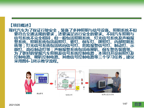
照明系统的组成及作用学习目标(1)了解照明系统的组成及作用;(2)了解信号警示系统的组成及作用一、照明信号系统的基本组成现代汽车为了保证行驶安全,装备了多种照明与信号设备。
照明系统不但要符合交通法规的要求,还要满足运行安全的要求。
不同汽车照明与信号系统不完全相同,但一般包括照明系统、灯光信号系统及声响报警系统。
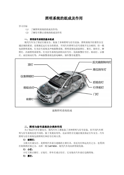
照明系统包括前照灯、雾灯、倒车灯、牌照灯、内部照明系统等;灯光信号系统包括转向信号灯、危险报警信号灯、制动灯、示廓灯、高位制动灯等;声响报警系统包括电喇叭、倒车警告装置等。
速腾照明系统组成二、照明与信号系统的分类和作用为了保证汽车行驶安全,现代汽车上都装备了多种照明与信号设备,但不同汽车照明与信号系统也是不同的,除了美观实用外,还必须符合交通法规及保证行车安全。
汽车照明与信号系统包括照明灯和信号灯两大类。
1)前照灯:又称大灯或头灯,是照明汽车前方道路的主要灯具。
有近光灯和远光灯之分。
也有四灯制和两灯制之分,功率一般为40~60W。
现代汽车均向四等制发展。
2)小灯:小灯又称示廓灯、示宽灯、停车灯或示位灯。
它安装在汽车前后边缘四角。
3)雾灯:用于雨雪天气行车时道路照明,有前雾灯和后雾灯两种。
4)仪表灯照明灯:用于仪表照明,以便于驾驶员获取行车信息和进行正确操作,其仪表灯数量依车型而定。
5)顶灯:用于车内照明。
有的车辆顶灯还具有门灯的作用,即当车门关闭不严会亮,以便提醒驾驶员注意6)牌照灯:安装在汽车尾部的牌照上方,用于夜间照亮汽车牌照。
工作灯。
用于在排除汽车故障或检修时提供照明。
2.警告信号灯的分类及作用1)转向信号灯:在汽车转弯时,发出明暗交替的闪光信号,以示汽车向左或向右转向行驶,转向灯一般有四只或六只,光色为橙色。
2)危险报警灯:与转向信号灯共用。
当车辆出现故障停止路面上时,按下危险报警开关,全部转向灯同时闪亮,提醒其他车辆避让。
3)制动灯:安装在汽车后面,当踩下制动踏板时,便发出较强的红光,以示本车制动或减速停车,向后车或行人发出灯光信号以便提醒。
汽车电器设备教案

汽车电器设备教案第一章:汽车电器设备概述1.1 汽车电器设备的作用1.2 汽车电器设备的发展历程1.3 汽车电器设备的分类与组成1.4 汽车电器设备的重要性与日常维护第二章:电源系统2.1 蓄电池的结构与工作原理2.2 发电机的作用与类型2.3 电压调节器的功能与调整2.4 电源系统的故障诊断与维修第三章:启动系统3.1 启动机的组成与工作原理3.2 启动机的控制原理与电路3.3 启动系统的主要部件与检修3.4 启动系统的常见故障与排除第四章:点火系统4.1 点火系统的基本原理与类型4.2 点火线圈、点火塞的结构与检修4.3 点火提前角的调整与控制4.4 点火系统的故障诊断与维修第五章:照明与信号系统5.1 照明系统的基本组成与功能5.2 信号系统的种类与作用5.3 照明与信号系统的故障诊断与维修5.4 照明与信号系统的日常维护与保养第六章:汽车空调系统6.1 汽车空调系统的作用与类型6.2 制冷剂的作用与回收方法6.3 空调压缩机的工作原理与检修6.4 空调系统的故障诊断与维修第七章:防盗系统7.1 汽车防盗系统的基本原理7.2 防盗装置的类型与作用7.3 防盗系统的故障诊断与维修7.4 防盗系统的日常维护与保养第八章:电动调节装置8.1 电动调节装置的种类与作用8.2 电动座椅的调节原理与检修8.3 电动后视镜的调节原理与检修8.4 电动调节装置的故障诊断与维修第九章:汽车电子控制系统9.1 汽车电子控制系统的概述9.2 电子控制单元(ECU)的结构与功能9.3 传感器的作用与类型9.4 汽车电子控制系统的故障诊断与维修第十章:汽车电器设备故障诊断与检测方法10.1 故障诊断的重要性与方法10.2 故障检测设备与工具的使用10.3 常见故障案例分析与排除10.4 汽车电器设备的定期检查与维护重点和难点解析重点环节:1. 汽车电器设备的作用与重要性2. 各个系统的结构与工作原理3. 故障诊断与维修方法4. 日常维护与保养难点环节:1. 电子控制单元(ECU)的结构与功能2. 传感器的作用与类型3. 故障检测设备与工具的使用4. 常见故障案例分析与排除详细补充和说明:重点环节1:汽车电器设备的作用与重要性汽车电器设备是现代汽车的重要组成部分,它们为汽车提供了照明、启动、点火、空调等功能,保障了汽车的安全性和舒适性。
6照明和信号系统-汽车电器设备(英文版)
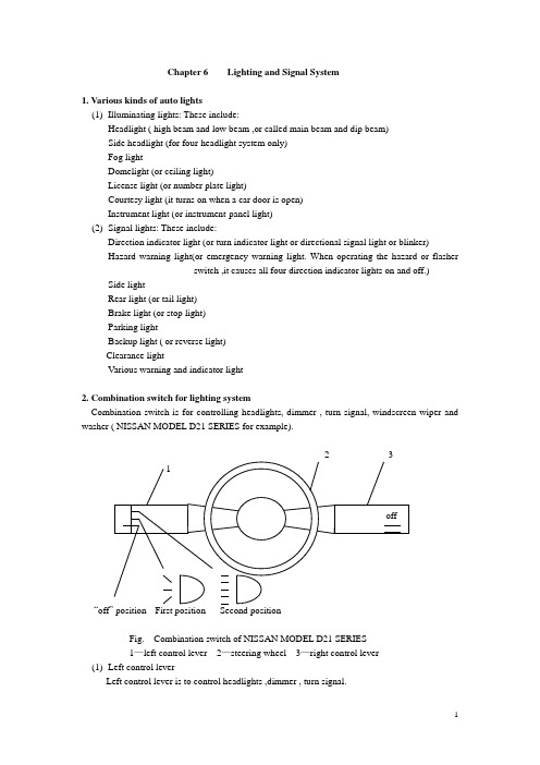
Chapter 6 Lighting and Signal System1. Various kinds of auto lights(1)Illuminating lights: These include:Headlight ( high beam and low beam ,or called main beam and dip beam)Side headlight (for four-headlight system only)Fog lightDomelight (or ceiling light)License light (or number plate light)Courtesy light (it turns on when a car door is open)Instrument light (or instrument-panel light)(2)Signal lights: These include:Direction indicator light (or turn indicator light or directional signal light or blinker)Hazard warning light(or emergency warning light. When operating the hazard or flasherswitch ,it causes all four direction indicator lights on and off.) Side lightRear light (or tail light)Brake light (or stop light)Parking lightBackup light ( or reverse light)Clearance lightVarious warning and indicator light2. Combination switch for lighting systemCombination switch is for controlling headlights, dimmer , turn signal, windscreen wiper and washer ( NISSAN MODEL D21 SERIES for example).“offFig. Combination switch of NISSAN MODEL D21 SERIES1—left control lever 2—steering wheel 3—right control lever(1)Left control leverLeft control lever is to control headlights ,dimmer , turn signal.●Lighting:Turn the switch to the first position: The side, tail, license plate and instrument panel lights will come on.Turn the switch to the second position: Headlights will come on and all the other lights remain on. To select the high beam, push the level forward. Pull it back to select the low beam.●Passing signal:Pulling the lever toward you will turn on the passing signal even when the headlight switch is “off”.●Turn signal:Move the lever up or down to signal to the turning direction. When the turn is completed, the turn signals cancel automatically.●Lane change signal:To indicate a lane change, move the lever up or down to the point where lights begin flashing.(2)Right control lever2—speed: “off”positionlow speed pull to washhigh speed2—speed with mist switch mist“off”positionlow speed pull to washhigh speed2—speed with intermittence “off”positionintermittentlow speed pull to washhigh speedTurn the ignition switch to “ACC” or “on” and move the lever down to operate the wiper.Move the lever up to wipe off a misty windscreen if this equipped. The wiper will operate only once.Pull the lever toward you to operate the washer.3. Relays and bulbs3.1 Relays(1)Function:Relays use a low control current to operate a solenoid, then the switch contacts can transmit very high working current.(2)Types of relaysThere are three basic types: normally-open (make)Normally-closed (break)Double-throw (changeover)88 86 85 88a 87 86 85 87a 87 86 85 88a 87aFig. Relays(3) Operation:A relay can be defined as an electromagnetic switch in which the contacts are actuated by asolenoid (an electromagnetic coil). The control current needed to operate the electromagnet is only 0.2 to 1 A, depending on the relay. However, the switch contacts can transmit very high working currents(up to 2000A for instance at the starting motor solenoid switch). It is advantageous to use a relay so that the high load between the electrical source and the consumer can be transmitted through a wire of generous cross-section and this can be kept short, whereas the control wire between the switch and the relay coil, which is subject to only very low loads, can be made as long as necessary.(3)Application:Relays are often used in horn, headlight, electric fuel pump, fog light and starting circuits.3.2 Light bulbs(1) Types of light bulbThere are two basic types according to the number of filament:Single-filament bulbDouble-filament bulbFor headlight bulbs, two types of common incandescent and halogen-wolfram bulbs can be of option.(3)Power selection of typical light bulbsBulb power should be selected according to the specifications. This is a example for Audi 100.Headlight 60 W/55 W (double filament for high beam and low beam,enclosed-type headlight)Side light 8 WStop light/tail light 21 W/5W (double filament)Direction indicator light 21 WReverse light 21 WLicense plate light 5 WFog light 55WParking light 4WDomelight 10WInstrument-panel light 2W4. Headlight4.1 Types of headlightThere two basic types of round and rectangular headlights according to the shape, and two types of semi-enclosed and enclosed (or vacuum) headlights according to the construction.The rectangular type has become increasingly popular in recent years. They fit the tapered front-end style of the modern cars.4.2 Headlight circuit:A typical headlight circuit is as shown below.dipswitchhigh beam leftlow beam lefthigh beam indicatorhigh beam rightlow beam rightside leftrear leftinstrument panelside rightrear rightlicense plate4.3 OperationRefer to the combination switch (left control lever).4.4 Headlight aimingAiming adjustment is made by turning screws in a spring-loaded holder. Top screw is for up-and-down adjustment. Side screw is for left-to-right adjustment.2Round type rectangular type1—Horizontal aim adjusting screw 2—Vertical aim adjusting screw4.5 Inspecting headlight circuitAccording to the different wiring circuit, checking procedures are different. Generally follow below.●Use public fuse: One bulb is not working. Check bulb or connection.Two or more bulbs are not working. Check fuse and switch.●Use separate fuse: One bulb is not working. Check fuse and bulbTwo or more bulbs are not working. Check switch or relay.5. Stop light (or brake light)Stoplight often uses double-filament bulbs, sharing with tail light. This is similar to those used in the headlights. The stop light must be brighter than tail light so that it can be seen in daylight.5.1 Stop light circuit:A typical stop light circuit is as shown below.5.2 OperationWhen depressing brake pedal, the stop light switch closes. Stop lights come on.5.3 Types of stop light switchThere are two basic types.Mechanical attached to brake pedalAttached to operating mechanismPressure-activated hydraulicPneumatic (for air pressure braking system)contactsspringterminalmechanical type pressure-activated typeFig. Schematic view5.4 Inspecting stop light circuit●One bulb is not working: check bulb or connection.●Two bulbs are not working: check fuse, then stop light switch. For checking stop lightswitch, you can directly connect two terminals and pinpoint whether the switch isoperative or not.6. Backup light (or reverse light)The backup lights come on when the shift lever is moved to“R”position. At the same time, the reverse alert device sounds.6.1 Backup light circuitA typical backup light circuit is as shown below.reverse lightFig. Simplified backup light circuit6.2 OperationWhen shifting into reverse, reverse switch is closed. Reverse light comes on. Meanwhile, current flows through horn and it sounds. At the same time, current also flows through coil L1 and coil L2. As two magnetic field directions are opposite, the resultant magnetic force is poor. Relay contacts remain closed. After the capacitor is charged, current and magnetic field in coil L2 disappears. The resultant field is strong enough to open the relay contacts. Horn stops sounding. Then the capacitor discharges through two coils. This resultant field keeps contacts still open until it discharges fully. Then relay contacts close again and horn resumes sounding. This cycle repeats while the reverse light switch is closed.6.3 Inspecting backup light circuit:●One bulb is not working: check the bulb or connection.●Two bulbs are not working: if it sounds, check the circuit.If it doesn’t sound, check fuse and switch.●Bulbs are on, but no sound: check the reverse alert device. (procedure: horn, contacts,capacitor, coils)7. Direction indicator lightThis is often called the flasher circuit. In this circuit, a flasher relay makes and breaks the current flow between 60 to 120 times every minute, so producing a flashing light.7.1 Direction indicator light circuitA typical direction indicator light circuit is as shown below.Front leftRear leftFig. Simplified direction indicator light circuit7.2 Types of flasher and operationThere are three types of flasher.(1)Hot wire type: It uses resistance wire. When current flows, it expends and contracts as itheats up or cools down, to operate contacts.(2)Capacitor type: It uses capacitor, charging and discharging. This activates the two coils tooperate the contacts. (Refer to backup light)(3)Electronic type: It uses capacitor, charging and discharging. This activates the triodes tooperate the circuit.When moving up or down the direction indicator switch, the flasher works and intermittently allows the current to flow. This will makes and breaks the right or left direction indicator light circuit to give a turn signal.7.3 Inspecting direction indicator light circuit●If one bulb is not working, check the bulb or connection.●If one-side bulbs are not working, check indicator switch.●If all bulbs are not working, check fuse, ignition switch, flasher unit.●If no flashing or kept on, check flasher unit.8. Electric hornMost horns are of the vibrating diaphragm type. To get a melodious sound, cars are often equipped with two horns of different tones. So it better to use horn relay to pass high current.8.1 Horn circuitA typical horn circuit is as shown below.8.2 OperationWhen depressing the horn button, horn relay is activated. Magnetic coil makes contact points close. Current flows from battery to horns through horn relay. The horns sound.8.3 Inspecting horn circuit●One horn loses sound: check horn or connection. Tune up horn if necessary.●Two horns lose sound: check fuse, horn button switch and relay.●Horn sound is low: check battery condition, relay contact points condition, and tune uphorns if necessary.8.4 Horn adjustment:●Tone adjustment: adjust the gap between iron core and iron armature in the horn.●Volume adjustment: adjust the pressure of contacts inside the horn by adjusting screw.9. Optical fiber lightingIn many cars, the instrument panel requires lights at many places to illuminate the speedometer, the indicating gauges, and the various controls. Because of the small spaces available, it becomes a problem to locate light bulbs where they are needed. To eliminate this problem, some cars use fiber-optic conductors. Theses conductors are made up of a very large number of extremely fine and flexible threads, or fibers , of pure glass which are bound together into a bundle, or cord. Each fiber has the property of being able to conduct light, even around bends or corners. As light starts down the fiber, it is reflected off the outer surface of the fiber. If the fiber is curved, the light keeps bouncing off the outer surfaces with little loss. By the time the light comes out the other end of the fiber, it is almost as strong as when it entered.Now, to utilize this effect, fiber bundles(each with many fibers) are run from a central light source to the various outlets on the instrument panel where light is needed. Therefore, only one light bulb is needed to provide light at many places. Installation and servicing problems are made easier to solve by the use of the fiber bundles. Only one light bulb needs to be replaced if a burnout occurs, the fiber bundles can be bent almost any way without damaging them.。
汽车照明信号系统课件
6.2 前照灯及其控制电路
汽车在白天行驶时,如果 遇到阴沉沉的雨雪天气,或 通过黑暗的涵洞、隧道时, 驾驶员为了行车安全而打开 前照灯,可有时在光线转亮 之后一直到停车断开点火开 关,容易忘记关灯。
6.2 前照灯及其控制电路
6.2.4 前照灯类型
按光学组件的结构不同,将前照灯分为半封闭式、封闭式两种。
半封闭式前照灯的结构如图6-16a、图6-17和图6-18所示,其配光镜是 靠卷曲反射镜边缘上的牙齿而紧固在反射镜上的,两者之间垫有橡胶密 封圈,灯泡只能从反射镜后端装入。
a)半可折式(白炽灯泡) b)封闭式灯泡
图6-4 以发光二极管LED为光源的汽车后组合灯
10
第6章 汽车照明信号系统
6.1 汽车灯具
常见内部灯具有顶灯、阅读灯、行李厢灯、门灯、踏步灯、 仪表照明灯、报警及指示灯、工作灯等,如图6-5所示。
图6-5 常见汽车内部灯具 1—发动机罩下灯;2—工作灯;3—仪表照明灯、报警指示灯; 4—顶灯;5—门灯;6—阅读灯;7—行李厢灯;8—开关照明灯
丝焊在反射镜底座的灯丝支架上,反射镜的反射面经真空镀 铝。其结构如图6-16b、c所示。
a)半可折式(白炽灯泡) b)封闭式灯泡 c)封闭式卤素灯泡 图6-16 单通前照灯类型
26
第6章 汽车照明信号系统 (1)投射式前照灯。
6.2 前照灯及其控制电路
投射式前照灯外形特点是装用很厚的无刻纹的凸型 散光镜,由于反射镜是椭圆形的,所以外径很小, 结构如图6-19所示。
灯非常相似(图6-22),亮度是卤素灯泡的2.5倍,寿命可达
卤素灯泡的5倍。
图6-21 HID气体放电灯灯泡实物
29
第6章 汽车照明信号系统
6.2 前照灯及其控制电路
中职汽车电器设备构造与维修(电子科技大学出版社)教案:照明与信号系统——前照灯控制电路
电容式闪光器结构:它由一只大容量电解电容器和双线圈继电器组成。
工作原理:接通转向灯开关(左或右)后,串联线圈经触点、转向信 号灯构成回
教
学
内
容
大。产生较强磁场,吸动衔铁,使触点张开。此过程中,串联线圈通电时间极短,转向信号灯不亮。触点张开后电容器经串联线圈、并联线圈、转向灯开关、转向灯及转向指示灯构成充电回路.由于充电电流很小,此时转向灯与转向指示灯不亮。触点在串并联线圈的合成磁场(方向相同)作用下,仍保持张开状态。电容器充足电后.并联线圈电流消失,铁心吸力减小,触点在复位弹簧作用下闭合,转向灯与转向指示灯亮;同时,电容器经并联线圈及触点放电,由于串联线圈与并联线圈磁场方向相反,铁心吸力极小,触点保持闭合状态。当电容器放电结束后,并联线圈电流消失,在串联线圈磁场作用下,触点再次张开,转向灯与转向指示灯变暗,电容在电容器再次充电。如此周而复始,转向灯与转向指示灯不停地以此频率闪烁。
在汽车起步、转弯、变更车道或路边停车时,需要打开转向信号灯以表示汽车的趋向,提醒周围车辆和行人注意。转向信号灯系统由闪光继电器(简称闪光器)、转向开关、转向灯和转向指示灯等组成。当接通危险报警信号开关时,所有转向信号灯同时闪烁,表示车辆遇紧急情况,请求其他车辆避让。根据GB 7258—1997 机动车运行安全技术条件》规定,危险报警灯不得受点火开关控制。
教学设备
板书,多媒体
教学
环节
教学活动内容及组织过程
个案补充
教
学
内
容
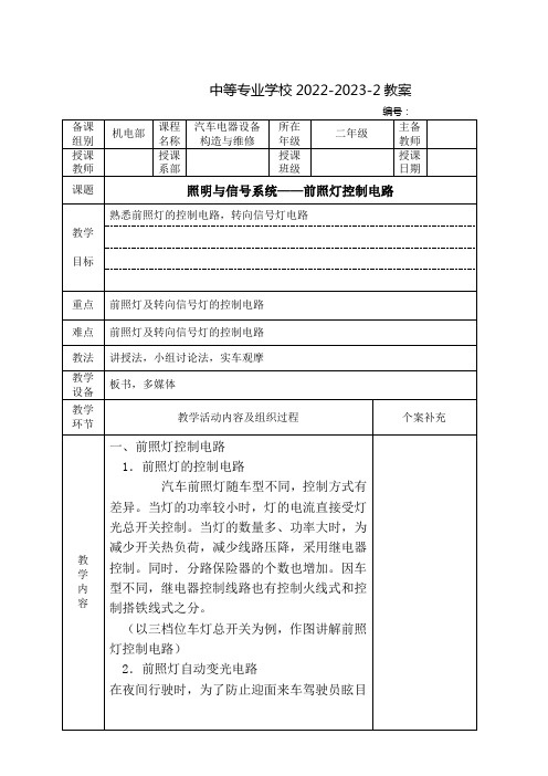
一、前照灯控制电路
1.前照灯的控制电路
汽车前照灯随车型不同,控制方式有差异。当灯的功率较小时,灯的电流直接受灯光总开关控制。当灯的数量多、功率大时,为减少开关热负荷,减少线路压降,采用继电器控制。同时.分路保险器的个数也增加。因车型不同,继电器控制线路也有控制火线式和控制搭铁线式之分。
《汽车电器》教案
《汽车电器》教案一、教学目标1. 让学生了解汽车电器的基本概念、组成和作用。
2. 使学生掌握汽车电器的主要部件及其工作原理。
3. 培养学生分析问题和解决问题的能力,提高学生的实践操作技能。
二、教学内容1. 汽车电器的基本概念1.1 汽车电器的定义1.2 汽车电器的作用2. 汽车电器的组成2.1 电源系统2.2 启动系统2.3 点火系统2.4 照明与信号系统2.5 电动调节系统2.6 车载电器设备3. 汽车电器的主要部件及其工作原理3.1 蓄电池3.2 发电机3.3 启动机3.4 点火线圈3.5 火花塞3.6 照明灯3.7 信号灯3.8 电动调节器3.9 车载电器设备的工作原理三、教学方法1. 采用讲授法,讲解汽车电器的基本概念、组成和作用。
2. 采用演示法,展示汽车电器的主要部件及其工作原理。
3. 采用实践操作法,让学生动手操作,提高实践能力。
四、教学步骤1. 引入新课:介绍汽车电器的基本概念。
2. 讲解汽车电器的组成:分别讲解电源系统、启动系统、点火系统、照明与信号系统、电动调节系统和车载电器设备。
3. 讲解汽车电器的主要部件及其工作原理:分别讲解蓄电池、发电机、启动机、点火线圈、火花塞、照明灯、信号灯、电动调节器和车载电器设备。
4. 实践操作:让学生动手操作汽车电器设备,提高实践能力。
五、教学评价1. 课堂问答:检查学生对汽车电器基本概念的理解。
2. 课后作业:布置有关汽车电器组成和原理的题目,巩固所学知识。
3. 实践操作考核:评估学生在实践操作中的表现,检验学生的动手能力。
六、教学资源1. 教材:《汽车电器》2. 教具:汽车电器实物、示意图、教学模型3. 课件:制作相关的教学课件,用于辅助讲解和展示七、教学环境1. 教室:布置宽敞明亮的教室,便于学生学习和操作2. 实践操作区:设置汽车电器实践操作区,配备必要的工具和设备八、教学安全1. 强调学生在实践操作中的安全注意事项2. 指导学生正确使用工具和设备,防止意外伤害九、教学拓展1. 组织学生参观汽车电器生产厂家,了解汽车电器的生产工艺和流程2. 邀请汽车电器专家进行讲座,分享汽车电器行业的发展趋势和技术创新十、教学计划1. 课时安排:共计40课时,每课时45分钟2. 教学进度:按照教案进行教学,确保每个知识点得到充分讲解和实践3. 复习与巩固:每节课结束后,安排10分钟的时间进行复习和巩固所学知识重点和难点解析一、教学目标1. 理解汽车电器的基本概念及其在汽车中的作用。
汽车电器设备原理与维修-照明与信号系统
2021/3/26
1/47
目录
6.1.1任务导入
随着汽车技术的不断发展,汽车照明技术越来越完善,从传 统的固定前照灯发展到前照灯随转系统,从传统的卤钨灯 泡发展到目前的疝气大灯。那么,当前汽车前照灯有哪些 控制功能?常见故障有哪些?要掌握这些内容,应进入下 面的学习任务:
(1)前照灯结构、控制电路及故障检修。
声音低哑、喇叭按钮放松后喇叭一直响等故障。 可能原因及检修方法见表6-3。
2021/3/26
25/47
目录
6.2.3任务实施 (1)认识各种类型的喇叭。 (2)调整喇叭音量和音调。 (3)喇叭的控制电路检测。
2021/3/26
26/47
目录
6.3.1任务导入 目前汽车除了照明和喇叭信号装置外,还有一些信号系统,
液压式、气压式、弹簧式等类型。
2021/3/26
36/47
目录
(2)制动信号灯电路 l)三灯组合式尾灯电路
1-灯光开关;2-制动信号灯开关;3-转向信号灯开关;4-左转向信号灯;5-左制动灯; 6-左驻车灯;7-高位附加制动灯;8-右驻车灯;9-右制动灯;10-右转向信号灯
2021/3/26
37/47
2021/3/26
12/47
目录
5.雾灯及控制电路 桑塔纳2000雾灯控制电路
2021/3/26
13/47
目录
6.典型照明系统控制电路 桑塔纳轿车照明系统电路控制原理
2021/3/26
1-点火开关;2-变光和超车灯开关; 3-转向灯开关;4-车灯开关; 5-中间继电器;6-牌照灯; 7-雾灯继电器;8-雾灯开关; 9-行李箱灯;10-前顶灯; 11-点烟器照明灯;12-雾灯开关照明灯; 13-后风窗除霜器开关照明灯; 14-空调开关照明灯; 15-雾灯指示灯;16-后雾灯; 17-前雾灯;18-仪表灯; 19-时钟照明灯;20-右前照灯; 21-远光指示灯;22-左前照灯; 23-右前后小灯;24-左前后小灯 ; 25-仪表灯调节电阻
汽车电器设备教案
汽车电器设备教案一、教学目标1. 了解汽车电器设备的基本组成和功能。
2. 掌握汽车电器设备的主要部件及其工作原理。
3. 学会诊断和维修汽车电器设备常见故障。
二、教学内容1. 汽车电器设备的基本组成1.1 电源系统1.2 启动系统1.3 充电系统1.4 点火系统1.5 照明系统1.6 信号系统1.7 仪表系统1.8 防盗系统2. 汽车电器设备的主要部件及其工作原理2.1 电源系统的主要部件及其工作原理2.2 启动系统的主要部件及其工作原理2.3 充电系统的主要部件及其工作原理2.4 点火系统的主要部件及其工作原理2.5 照明系统的主要部件及其工作原理2.6 信号系统的主要部件及其工作原理2.7 仪表系统的主要部件及其工作原理2.8 防盗系统的主要部件及其工作原理三、教学方法1. 采用讲授法,讲解汽车电器设备的基本组成和功能。
2. 采用案例分析法,分析汽车电器设备的主要部件及其工作原理。
3. 采用实践操作法,让学生动手诊断和维修汽车电器设备常见故障。
四、教学准备1. 教室环境布置:挂图、实物展示等。
2. 教学设备:汽车电器设备模型、工具等。
五、教学评价1. 课堂问答:检查学生对汽车电器设备基本知识和原理的理解。
2. 实操考核:评估学生在实际操作中诊断和维修汽车电器设备的能力。
3. 课后作业:布置相关题目,巩固所学知识。
六、教学内容(续)4. 汽车电器设备的故障诊断与维修4.1 故障诊断方法4.1.1 目视检查4.1.2 试车检验4.1.3 仪器检测4.2 故障维修流程4.2.1 维修步骤4.2.2 维修注意事项4.3 常见故障案例分析4.3.1 电源系统故障案例4.3.2 启动系统故障案例4.3.3 充电系统故障案例4.3.4 点火系统故障案例4.3.5 照明系统故障案例七、教学方法(续)4. 实践操作法:让学生通过实际操作,学会使用专业工具进行汽车电器设备的故障诊断与维修。
5. 小组讨论法:分组讨论故障案例,培养学生团队协作和解决问题的能力。
- 1、下载文档前请自行甄别文档内容的完整性,平台不提供额外的编辑、内容补充、找答案等附加服务。
- 2、"仅部分预览"的文档,不可在线预览部分如存在完整性等问题,可反馈申请退款(可完整预览的文档不适用该条件!)。
- 3、如文档侵犯您的权益,请联系客服反馈,我们会尽快为您处理(人工客服工作时间:9:00-18:30)。
单元教学设计首页
总第 31— 36课时
课时教学设计续页
(4)转向信号灯:一般有左前、右前、左后、右后四个,也有在车辆侧面安装转向灯的,大多数为对称安装。
(二)信号系统的基本电路图及原理
1、组合开关式
在黑板上画出该电路图。
左转向时:
将转向信号灯开关拨至左侧位置
蓄电池正极→点火开关点火档电源(15)→熔丝10→危险报警开关1号端子→危险报警开关常闭触点→危险报警开关2号端子→闪光继电器2号端子→闪光继电器3号端子→转向信号开关14号端子→转向信号开关13号端子→分别至左前、左边、左后转向信号灯及仪表板内左转向信号指示灯→搭铁31。
右转向时:
备注
课时教学设计续页
教学程序
第33、34课时讲课时间年月日星期
教学内容讲解、导学方法(三)桑塔纳信号系统电路图及原理
画出桑塔纳转向与危险报警信号电路图。
左转向时:
将转向信号灯开关拨至左侧位置
蓄电池正极→点火开关点火档电源(15)→熔丝
S4→危险报警开关端子15→危险报警开关常闭触
点→危险报警开关端子49→闪光继电器端子49→
闪光继电器端子49a→转向信号开关端子49a→转
向信号开关端子L→分别至左前左后转向信号灯
及仪表板内左转向信号指示灯→搭铁31。
右转向时:
将转向信号灯开关拨至右侧位置
课时教学设计续页
教学程序
第35课时讲课时间年月日星期
教学内容讲解、导学方法第二节倒车信号装置
倒车灯及倒车报警器主要是在汽车倒车时,提
醒行人及其它车辆驾驶员。
组成:倒车灯开关、倒车灯、倒车报警器等组
成。
1、倒车灯开关
一般装在汽车变速器盖上的倒车档位置。
当变速杆将倒档变速叉轴拨到倒档位置时,倒档叉
轴上的凹槽恰好对准钢球,钢球在弹簧作用下带动
膜片和接触盘下移,使静触点与接触盘接触,使两
接线柱导通。
2、倒车灯与倒车警报器电路
课时教学设计续页
教学程序
第35课时讲课时间年月日星期
教学内容讲解、导学方法
第三节喇叭
一、作用
用来警告行人和其它车辆,以引起注意,保证
行车安全。
二、分类
按发音气喇叭
动力分普通电喇叭(有触点
电喇叭
电子电喇叭(无触点
螺旋形高音
按外形筒形按频率
盆形低音
筒形螺旋形
盆形气喇叭
二、电喇叭工作过程
如图,当按下喇叭按钮时,“+”→线圈→触点→按钮→搭铁
电流流经线圈时产生电磁吸力,向下吸上铁芯,上铁芯下移,与下铁芯碰撞,同时使触点断开,使线圈断电,电磁吸力消失,膜片电动上铁芯回位,使触点再次闭合,如此反复。
下铁芯与上铁芯碰撞产生较低的基本频率,激励与膜片一体的共鸣盘产生共鸣,从而发出比基本频率强且分布比较集中的谐音。
三、喇叭继电器
由于现代汽车大多装有双喇叭,消耗电流较
大,为保护喇叭触点不被烧蚀,通常在喇叭电路中
设有继电器,喇叭按钮只有小电流通过,用以控制
喇叭继电器,而供喇叭的大电流只流经喇叭继电
器,不流经喇叭按钮。
备注。