施耐德a型控制器说明书
施耐德 双电源MG ATS用户手册

ATS技术操作规程一.送电前检查1.检查接线是否正确检查ACP(辅助控制板)与BA或UA(控制器)之间9#.10#连接端子对应是否正确;检查ACP上P25M与断路器之间接线是否正确(详见“ATS接线”单页)2.检查BA或UA控制器顶部17#.18#;20#.21#端子是否安装,17#.18#;20#21#已分别短封好;3.检查断路器电操左下方的手动(manu)和电动(auto)切换拨钮是否在“auto”位置;4.检查电操与BA或UA控制器的操作电压是否一致(220V~或380V~);5. 检查ATS装置无异物;6.检查ACP上P25M是否已在合闸位置。
二.操作试验1.预设电源转换时间: 通过控制器右上方时间整定钮调整;2.将BA或UA控制器上的选择开关置于“STOP”位置,将ACP上“N(工作电源)”及“R(备用电源)”侧P25M分别合闸(两台断路器电操储能)。
3.将BA或UA控制器上的选择开关转到“auto”位, N断路器合闸,BA或UA“N”、“R”侧ON或OFF指示断路器的合分状态。
观察控制器指示与断路器电操上的ON. OFF位置应一致;4.将ACP上N侧P25M开关分断模拟电源故障, 此时N侧断路器分断;R侧断路器合闸(系统自动转换到备用电源R侧); 合上N侧开关,电源应自动恢复到主电源(N)侧合闸---自投自复功能;5.将N侧断路器下端的故障试验推杆按入(模拟负荷故障),N侧断路器断开BA或UA控制器的N侧Fault指示灯亮(红色),电源并不转换到备用侧; 手动拨N侧断路器电操的储能手柄2次,(N侧断路器储能、合闸)故障复位,控制器N侧Fault指示灯灭, 恢复原始状态;6.将BA或UA控制器选择开关置“R”位, 则ATS强制在备用电源侧运行; 同样再置“N”位, ATS强制在工作电源运行,此操作过程中,控制器电源指示均正常;7.将选择开关置“manual /stop”位, 控制器指示灯全部灭,两台断路器均处于断开位置(储能状态)此时可手动操作:8.将电操手、电动切换钮置“manual”位, 两台开关均手动储能, 按电操的手动合分按钮,合N侧,电操指示ON位; 若再合R侧,则备用电源侧无法合闸,说明该装置具有机械联锁功能。
施耐德WATSNA系列说明书

WATSNA-63CB WATSNA-100CB WATSNA-160CB WATSNA-250CB WATSNB(C)-63CB WATSNB(C)-100CB WATSNB(C)-160CB WATSNB(C)-250CB WATSNB(C)-400CB WATSNB(C)-630 CB WATSND-63CB WATSND-100CB WATSND-160CB WATSND-250CB WATSND-400CB WATSND-630CB WATSNA-32~100 PC WATSNB-32~100 PC
!"# ! !
3 3
4 4
WATSG
!"#$%&
WATS G B - 100 4 R
!" !"#$% !"#$ G !"#$%& !" A B C D 3 3 4 4 !"# ! 63 100 160 250 400 630 ! !"#$% R S !"# !
2
WATSP
!"#$%&'(
WATSP
6
WATS
!"#$%&'()*
WATSP/WATS
B
!"#$%& B
!"#"$
!"
!"#$%
(mm) ! WATSPA-63 WATSPA-125 WATSPA-160 WATSPB(C)-125 WATSPB(C)-160 WATSPB(C)-250 WATSPB(C)-400 WATSPB(C)-630 WATSPB(C)-800 L(3p/4p) 350 360/410 385/445 445/495 470/530 500/570 570/660 570/660 710/830 W 210 230 230 200 200 200 290 290 300 H 125 125 125 125 125 170 170 170 190 L1(3p/4p) 320 330/380 355/415 415/465 440/500 470/540 540/630 540/630 680/800 W1 170 170 170 170 170 170 240 240 270 ! D( ) 5.5 6.5 6.5 6.5 6.5 8.5 9 9 11
ATNS_用户手册

④两路电源均正常情况下上电(或复位),常用电源方优先工 作。运行过程中工作电源故障时,自动切换到另一供电电源(对 B 型开 关转换延迟可调),双电源为对等优先权,互为备用电源。
控制器 工作电压① 工作频率 3 个工作位置 常用电源闭合 备用电源闭合
A(内置式) 220VAC 50/60Hz
■ ■
B(面板式) 220VAC 50/60Hz
■ ■
常用和备用电源均断开 (0 位) 3 种操作方式 自动操作 手动遥控 手柄操作② 自动操作 监控常用电源和自动切 换
■
■ ■ ■(三相断相、失压 检测)
:安全警示标志,提示您如果违规操作可能造成
人身安全危险或本开关的不可恢复性损坏。
;: 关键性操作,提示您使用不当时,可能使控制
器工作于非正常状态。
":提供另外的信息或简化的操作方法。
请注意: 电气设备应该让有资格的专业人员进行安装、操作、使用、维
护。未按使用手册操作而造成的不良后果,施耐德电气公司将不负任 何责任。
备用 电 源显 示 备用 电源 合
常用 电源 脱 扣 备 用电 源脱 扣
复位 按钮
外指 示接灯外引接线引 线端子
线端 子
1 2 3 4 5 6 7 8 9 10
常用 电源 NN UN VN WN
备用 电源 NR UR VR WR
复位按用户钮可根用据于具 体自需 要投自 不接 外自部 引复线 工作方式 用户可根据具体需要选接外部引线
6
常用 电源 脱扣
7
备 用电 源脱 扣
施耐德WATSNA双电源切换控制器说明书

IATSNA-100 63"卜形厂衫尺寸笊壬尺寸讦?IR寸U3MF 2")吋S| 1 L.3F4R,. Sg# 讣仍22、SMP) HI 1$ 曲 e A VH⑶ WO XO KO8MO 155551COS227 t2l«6535e15&B4i W05 2M HO I 4/0640 155 85 慢S227 V1 ta 4ourd 20 74 174 *15 ATSM 1® g畑MO 2W MO faxueo 也6S昵问tai91鮭15e< w皿 5 2CO XO I CO^IO 155 :5 1« .&Z» t21 4oex?s 20 7< 174 38 ISA222印a仝43L600 XC UO:3W17O 恨65低S®7 VI K652026a15& 6OD«yO «£O KO65 10S£^90 V1 3 20 74 174 的iso 1& TOOI 420640 ,55ATS24C A»372 27S uo曲W90 245eo2S73 1702£2S2G S63 52074174452248€25曲5 AT$2牺AV 62LW 275 MO | acieeo 245 »o 203 170 血520 S«»52O 74 174 45 224 ec 25 W5数码管显示1000E'UIJIJL!180 sesg 8180「8・UU剜5C:OF[机富甘于 a SMC■开矣內邯.ItMPMmXifcX.rnwawt IHkllitttl UiFBCIfifiKKI K2 XfTttO K3 K4 K5 迅时“昭KG K7 K6 HlftHR(S)OFF OFF 口ttQft OFF OFF OFF o OFF OFF OFF oOFF ON 互>i«H OFF OFF ON 5 OFF OFF ON 5ON ON貝披不自鼻OFF ON ON ts OFF ON ON isON 014 ON 30 ON ON ON 3oH11&示刘:代茫一空用m沥正京・闪亮一廉阳电源故处H2描示灯贰李一备用电滋正荒・闪亮一待用电灌数迈“3指示灯KTW-tt用电海两合H41SS灯灯交一备用电汲岗合M5H:灯亮一耒用电过涼fit护(仞阳&A行断毘开知HG#J: ]«-»用电总保巧(仪用NS1V亍04ii2开关)BariwaG千讥行诗的左値・氏1«丰■的切陡・S»Xffm««S红合刊BSif!行电洱皆換动件:LED 見示电按ta武手ttiie?«ti转换动作;毎用侧崔电制正朮状Q:W稔用电寿帝电E朋环銘授気示‘・功件状Q:見示SitI-:间倒计,N(R):竈期馬电审正常.阿晃致■朋电刎炖Ni(«f >:电源合rflN0<RB).竝制召工作—酒临:•火誓值号・齐於开关』入双分畑• Ot. F2nSM«KH切仗BB e»a进入»n«fi状审it仔浚“制处手育动灯亮工作子育紀方it・灯灭工仕子退1$方式钺磴懺(ME«<iw挖制需疑仗开关■ 曲远行状左审皿只商“皿員呦何!2方恥对丘幻川?ft«L在«M77ir ift 认・冃时itt入下一项dW<a: siifi力JV忆用m涝盒stan方只遥賂玫成安自动龙陨■鉞在违垃方真25用电洱合StQH方JViSSE蚁IUIB向初虑満OFFS!;在iSGm•二无NBRBSWrt伕2R开关TKJFR出曲他示厮仙行再扣FVM R【尺寸与连接IAl YQ3A如形x^、・cm外衫尺寸外彩尺夕齐扎尺勺LPMF Hpfrei inw> 2从C Hpr.r. y 丿HI B K> E即* A ZALY8ASA 型»0 2CO ®5320 W 56砂121 103 5 17 18 ue 14 d$ B賓■r a» os S 価66 W121 1S2 9?S 17 7A 1F4 » 18 W IM 46入梢鲂霸佼51反家劝Hf・JM370Ht!«标产砂含多组反诸住号丈3”异跋处形尺寸左生芒乂.祈与柜林利作前咨询公门eSHMK式时;3仆咛只开乩尺菇■耐。
施耐德电气 3A6382D 操作 零件手册 - GrindLazer
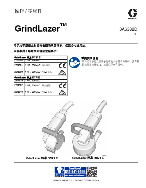
3A6382DZH操作/零配件GrindLazer™用于扁平混凝土和沥青表面物质的清除。
仅适合专业用途。
未获准用于爆炸性环境或危险场所。
GrindLazer 标准 RC71 EGrindLazer 标准 DC21 E重要安全说明请阅读本手册及磨床手册中的全部警告和说明。
熟悉操控装置并正确使用。
妥善保存所有说明。
目录23A6382D目录一般电动工具安全信息 . . . . . . . . . . . . 3警告 . . . . . . . . . . . . . . . . . . . . 4组件识别 . . . . . . . . . . . . . . . . . .6GrindLazer 标准 DC21 E . . . . . . . . . . 6GrindLazer 标准 RC71 E . . . . . . . . . . 7操作 . . . . . . . . . . . . . . . . . . . .8机器启动 . . . . . . . . . . . . . . . . . 8切割材料 . . . . . . . . . . . . . . . . . 8维护 . . . . . . . . . . . . . . . . . . .8零配件 - GrindLazer 标准 DC21 E . . . . . . .9零配件清单 . . . . . . . . . . . . . . . .9零配件 - GrindLazer 标准 RC71 E . . . . . . 10零配件清单 . . . . . . . . . . . . . . . 10技术数据 . . . . . . . . . . . . . . . . . . 11Graco 标准保修 . . . . . . . . . . . . . . . 13一般电动工具安全信息3A6382D 3一般电动工具安全信息警告阅读所有安全警告及说明。
施耐德LXM05A面板点动控制与模拟量控制
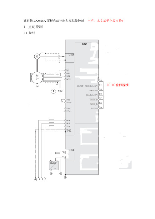
施耐德LXM05A面板点动控制与模拟量控制声明:本文基于空载实验!1.点动控制1.1接线1.2面板操作1.2.1 首次设置1.2.2 恢复出厂设置如果首次设置失误需要回到FSu重新设置,在面板中请进入drC→FSC,选择YES,即可回到FSu.1.3点动操作同时按住箭头按钮和ENT 键电机以高速运行。
2. 模拟量控制2.1接线2.2面板操作2.2.1 转速控制方式(1)将默认运行方式设定为转速控制。
为此要在DRC- / io-n 项下选择Sped 。
(2)应通过ANA1+ 来设定电机转速,当电压为 10V 时,转速为 3000转/ 分钟。
为此要在set- / a1ns 项下选择数值3000 。
(3)通过ANA2+ 来限制电机电流。
为此要在DRC- / A2mo 项下选择Curr 。
(4)当电压为 10V 时,电机电流的限值应为 0.5A 。
为此要在DRC- / A2im 项下选择数值5.00 。
检查电流限制。
请起动电机(输入信号ENABLE)。
将ANA1+ 设定为最大,然后使用ANA2+ 进行限制。
请在sta- / iaCt 项下查看电流值。
检查当前转速。
为此要在sta- / naCt 项下查看数值。
2.2.2 优化(1)自动调整的旋转方向TUN-/DiR/pnh: 首先正转,然后反转且返回到起始位置中(2)调整调节器参数(较硬 / 较软)TUN-/GAiN/100:控制器的硬度单位。
值为 100 相当于理论最佳值。
大于 100 的值表示调节控制比较硬,较小的值则表示控制比较软。
(3)开始优化 TUN-/Strt(按下ENT,开始自动优化)3. PLC编程将ANA1通道输出0-10V(用于转速给定)将ANA2通道输出0-10V(用于限制ANA1,即ANA1≤ANA2)4. 运行重新上电,将PLC RUN,将Enable的开关置ON,电机开始转动,改变ANA1+大小,转速也跟着变化. 将Enable的开关置OFF,电机停止。
施耐德电气 TAC I A 系列 MicroNet MZ800 系列控制器说明书
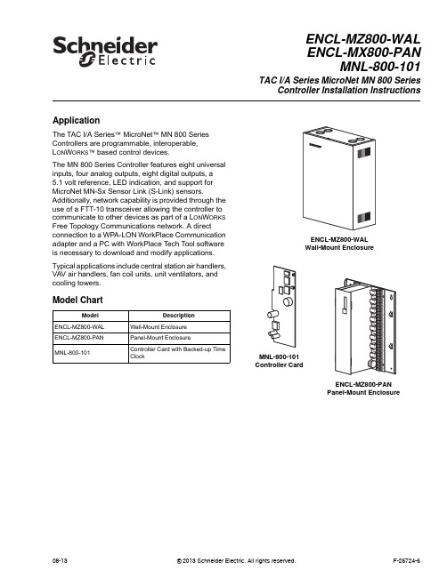
ApplicationThe TAC I/A Series™ MicroNet™ MN800 Series Controllers are programmable, interoperable,L ON W ORKS™ based control devices.The MN800 Series Controller features eight universal inputs, four analog outputs, eight digital outputs, a 5.1volt reference, LED indication, and support for MicroNet MN-Sx Sensor Link (S-Link) sensors. Additionally, network capability is provided through the use of a FTT-10 transceiver allowing the controller to communicate to other devices as part of a L ON W ORKS Free Topology Communications network. A direct connection to a WPA-LON WorkPlace Communication adapter and a PC with WorkPlace Tech Tool software is necessary to download and modify applications. Typical applications include central station air handlers, VAV air handlers, fan coil units, unit ventilators, and cooling towers.Model ChartModel DescriptionENCL-MZ800-WAL Wall-Mount EnclosureENCL-MZ800-PAN Panel-Mount EnclosureMNL-800-101Controller Card with Backed-up TimeClockENCL-MZ800-WALENCL-MX800-PANMNL-800-101TAC I/A SeriesMicroNet MN800 SeriesController Installation InstructionsENCL-MZ800-WALWall-Mount EnclosureMNL-800-101Controller CardENCL-MZ800-PANPanel-Mount Enclosure08-13© 2013 Schneider Electric. All rights reserved.F-26724-62© 2013 Schneider Electric. All rights reserved.F-26724-6Applicable DocumentationInstallationInspectionInspect carton for damage. If damaged, notify carrier immediately. Inspect controllers for damage. Return damaged products.Requirements (These items not provided):•Installer must be qualified, experienced technician.•Job wiring diagrams•Tools–Drill and bits for panel mounting screws–Digital Volt-ohm meter (DVM)–Static protection wrist strap•Class 1 or Class 2 power transformer supplying a nominal 24 Vac (20.4 to 30 Vac) witha minimum rating of 20 VA, 50/60 Hz per controller plus Digital Output (DO) loads (ifsame transformer is used). In European Community, transformer must conform to localstandards.•Terminators–One LON-TERM1 terminator required for free topologies–Two LON-TERM2 terminators required for bus topologiesPrecautions Warning:•Electrical shock hazard! Disconnect power before installing or removing the cover.•Follow Static precautions when installing this equipment.•Use copper conductors that are suitable for 167°F (75°C)•Make all connections according to electrical wiring diagram, national and localelectrical codes.F-Number DescriptionAudience Purpose F-26277TAC I/A SeriesMicronetMN-SX Series SensorsGeneral Instructions–Application Engineers –Installers –Service Personnel –Start-up Technicians Provides step-by-step installation and checkout procedures for TAC I/A Series MicroNet MN-SX Series Sensors. Also contains instructions for sensor operation.F-26303TAC I/A SeriesMicroNetSystem Overview –Application Engineers –Installers –Start-up Technicians –Service Personnel Provides an overview of the TAC I/A Series MicroNet System. It includes brief descriptions of the hardware and software components, and how they may be combined to create MicroNet networks and stand-alone systems.F-26580WorkPlace Tech Tool Engineering Guide –Application Engineers –Installers –Service Personnel –Start-up Technicians Provides engineering and technical information for applying and using all aspects of WorkPlace Tech Tool.F-26507TAC I/A Series MicroNet System Engineering Guide –Application Engineers –Installers –Service Personnel –Start-up Technicians Provides engineering and technical information to assist in designing a complete TAC MicroNet controller system using different architectures, components, and software.F-26304WorkPlace Tech Tool User’s Guide–Application Engineers –Installers –Service Personnel –Start-up Technicians Provides step-by-step instructions for using WorkPlace Tech Tool.F-26363EN-206 Guidelines forPowering Multiple Full-Wave and Half-WaveRectifier Devices froma CommonTransformer –Application Engineers –Installers –Service Personnel Offers guidelines for avoiding equipment damage associated with improperly wiring devices of varying rectifier types. Contains instructions for identifying device rectifier type, guidelines for correctly powering devices of varying rectifier types, and examples illustrating proper power wiring techniques.Static PrecautionsStatic charges damage electrical components. The microprocessor and associated circuitryare extremely sensitive to static discharge. Use the following precautions when installing,servicing, or operating the system.•Work in a static-free area•Discharge static electricity by touching a known, securely grounded object.•Use a wrist strap connected to earth ground when handling the controller’s printedcircuit board.Federal Communications Commission (FCC)This equipment has been tested and found to comply with the limits for a Class B digitaldevice, pursuant to Part 15 of the FCC Rules. These limits are designed to providereasonable protection against harmful interference in residential installations. Thisequipment generates, uses, and can radiate radio frequency energy and may cause harmfulinterference if not installed and used in accordance with the instructions. Even wheninstructions are followed, there is no guarantee that interference will not occur in a particularinstallation. If this equipment causes harmful interference to radio or television reception--which can be determined by turning the equipment off and on-- the user is encouraged to tryto correct the interference by one or more of the following measures:•Reorient or relocate the receiving antenna.•Increase the separation between the equipment and receiver.•Connect the equipment to an outlet on a circuit different from that to which the receiveris connected.•Consult the dealer or an experienced radio/television technician for help.Canadian Department of Communications (DOC)This class B digital apparatus meets all requirements of the Canadian Interference-CausingEquipment Regulations.Cet appareil numerique de la classe [B] respecte toutes les exigences du Reglement sur lematerial broilleur du Canada.European Community DirectivesThis equipment meets all requirements of European Community Directives for Low Voltage(72/23/EEC) and Electromagnetic Compatibility (89/336/EEC).Caution:This is a class A product. In a domestic environment this product may causeradio interference in which case the user may be required to take adequate measures.Location These controllers are suitable for indoor use only.Caution:•Avoid locations where excessive moisture, corrosive fumes, vibration, or explosivevapors are present.•Avoid electrical noise interference. Do not install near large contactors, electricalmachinery, or welding equipment.•Locate where ambient temperatures do not exceed 140°F (60°C) or fall below -40°F(-40°C) and relative humidity does not exceed 95% or fall below 5%, non-condensing.Mounting Panel Mount Installation (ENCL-MZ800-PAN)ENCL-MZ800-PAN uses a sheet metal mounting plate. The enclosure has four mountingholes. Mount in a vertical position as shown in Figure-1. Allow access for wiring and removalof the assembly for service.Use the mounting holes provided.F-26724-6© 2013 Schneider Electric. All rights reserved.34© 2013 Schneider Electric. All rights reserved.F-26724-6Caution:•Drilling holes in the controller or mounting plate voids warranty.•Do not drill into mounting plate or any other part of controller. Metal chips and other debris may short-circuit electronic components.1.Select mounting ing four #8 pan head screws, mount base of controller to a panel.3.Wire controller (See Wiring section).4.After wiring, remove aluminum cover plate.5.Remove protective tape from edge of card connector.6.Install printed circuit board. (See MNL-800-101 Printed Circuit Board Installation.)Figure-1ENCL-MZ800-PAN Panel Mounting Dimensions.Wall Mount Installation (ENCL-MZ800-WAL)ENCL-MZ800-WAL use sa sheet metal enclosure. The enclosure has four mounting holes and eight combination knockouts (1/2" to 3/4") (Figure-2). Mount in a vertical position and allow access for wiring and removal of the printed circuit board assembly for e the mounting holes and knockouts provided.Caution:•Drilling holes in the controller or enclosure voids the warranty.•Do not drill into the enclosure or any other part of the controller. Metal chips and other debris may short-circuit electronic components.1.Select mounting location.2.Remove ing four #8 pan head screws, mount controller.4.Wire controller (see Wiring section).5.Remove protective tape from edge of card connector.6.Install printed circuit board. (See MNL-800-101 Printed Circuit Board Installation.)F-26724-6© 2013 Schneider Electric. All rights reserved.5Figure-2ENCL-MZ800-WAL Wall Mounting Dimensions.WiringSee Figure-3 for terminal connections.A power transformer supplying a nominal 24 Vac (20.4 to 30 Vac) with a minimum rating of20 VA, 50/60 Hz per controller is required. The supply to the transformer must be providedwith a circuit breaker or disconnect. Use class 1 wiring for the transformer wiring.Figure-3Terminal Connections.6© 2013 Schneider Electric. All rights reserved.F-26724-6Caution:•Do not install the low voltage input/output wiring (UI/AO) in the same conduit with power or DO wiring with a potential greater than 30 Vac rms.•Use shielded cable if the low voltage input/output wiring (UI/AO) is installed in the same conduit with power or DO wiring with a potential less than 30 Vac rms.•Do not use the inside of the sensor enclosure or the wiring compartments of the MN 800 as a junction box for other control circuits.Although not required, shielded cable may used for AI, DI, and AO wiring. Fold the foil shield back over the cable jacket and compress it at the point of entry or exit of each controller. Use a sheathed cable connector in the knockout at the point of entry or exit.After the entire system has been installed and wired, verify wiring with the use of a DVM to insure against wiring errors, overvoltage, or short circuits.MNL-800-101 Printed Circuit Board Installation Mount the controller and complete wiring before installing the printed circuit board.1.Verify power is OFF .2.Follow the Static Precautions.3.Remove enclosure cover.Caution:Do not pull or push on the circuit board components when installing or removing the printed circuit board. Doing so may result in damage to the circuit board assembly.4.Remove and discard protected shipping tape from card slot.5.Slide printed circuit board into place (Figure-4).6.Replace enclosure cover.Figure-4Printed Circuit Board munications Wiring Caution:•Communication wire pairs must be dedicated to S-LK and MicroNet L ON W ORKS network (LON) communications. They cannot be part of an active, bundled telephone trunk.•Shielded cable is not required for S-LK or LON wiring.•If the cable is installed in areas of high RFI/EMI, the cable must be in conduit.•If shielded wire is used, the shield must be connected to earth ground at one end only by a 470K ohm 1/4 watt resistor. Shield must be continuous from one end of the trunk to the other.Communications wiring includes a connection between the controller and a TAC I/A SeriesMicroNet Sensor via the S-LK and a connection between the controller and the MicroNetL ON W ORKS Network (LON). An optional LON connection between the controller and oneTAC I/A Series MicroNet Sensor is also possible.Sensor Link (S-LK) WiringS-LK wiring powers and enables the MN-SX Sensor. The S-LK needs at least 24 gage(0.51mm), twisted pair, voice grade telephone wire. The capacitance between conductorscannot be more than 32 pF per foot (0.3m). If shielded cable is used, the capacitancebetween any one conductor and the others, connected to the shield, cannot be more than60 pF per foot (0.3m). Maximum wire length is 200 ft. (61m).Note:•Controller supports one TAC I/A Series MicroNet Sensor (MN-SX).•S-LK wiring is polarity insensitive.•If conduit is used between a TAC I/A Series Sensor and a controller, the MicroNetL ON W ORKS network and S-LK wiring can be in the same conduit.•S-LK wiring (not LON wiring) can be in the same conduit with UI, AO, and DI wiring.MicroNet L ON W ORKS Network (LON) WiringA Category 4, twisted-pair (two conductors) cable may be used for LON connection betweencontrollers and between a controller and an MN-SX sensor. LON wiring is polarityinsensitive.Caution:Do not mix with UI, AO, DI or DO types of wiring. If conduit is used between aTAC I/A Series Sensor and a controller, LON wiring and S-LK wiring can be in the sameconduit.MN 800 controllers use L ON W ORKS Free Topology Transceiver (FTT-10) and supportpolarity insensitive bus (daisy-chain) and free (all combinations of star, tee, and loop) wiringtopologies. A maximum of 62 nodes can be connected per segment.See TAC I/A Series MicroNet System Engineering Guide, F-26507 to design a MicroNetL ON W ORKS FTT-10 network, including recommended topologies and approved cable types. CheckoutStand-alone Controller1.Verify controlled devices are not powered or are in a controlled manual condition.2.Apply power to MN 800 controller.3.Check LED operation using Table-1.Table-1LED IndicationsLED Operation StatusGreenON Normally ON indicating controller is powered and not actively transmitting data on the LON. Flashes OFF Flashes OFF while actively transmitting data on the LON.AmberOFF Normally OFF unless actively receiving data from the LON. Flashes ON Flashes ON while actively receiving data from the LON.RedOFF(Neuron - normal communications) Indicates the Neuron is operating properly allowing normalcommunications to and from the HVAC application.OFF(Neuron - Off line) Neuron responds to network management messages only. In this state,communication to and from the HVAC application is not possible. To Correct, place the Neuron on-line by downloading an application using WP Tech or configure using a third party managementtool.BlinkingThe service LED blinks at 0.5 Hz rate (1 second ON, 1 second OFF) to indicate that the Neuron isunconfigured (i.e. communications parameters not loaded). Corrective action: Configure theNeuron by downloading an application using the Work Place Technician’s Tool or configure theneuron using a third party management tool.ON Indicates Neuron is not operating properly. Replace controller.F-26724-6© 2013 Schneider Electric. All rights reserved.7Distributed, manufactured, and sold by Schneider Electric. I/A Series trademarks are owned by Invensys Systems, Inc. and are used on this product under master license from Invensys. Invensys does not manufacture this product or provide any product warranty or support. For service, support, and warranty information, contact Schneider Electric at 1-888-444-1311.All brand names, trademarks and registered trademarks are the property of their respective owners. Information contained within this document is subject to change without notice. Schneider Electric 1354 Clifford Avenue, P.O. Box 2940, Loves Park, IL 61132-2940, USA 1-888-444-1311 /buildingsF-26724-6August 2013 ptm © 2013 S c h n e i d e r E l e c t r i c . A l l r i g h t s r e s e r v e d .4.Power down MN 800 controller if the programming will be done later, or program using WorkPlace Tech.Figure-5LED Indicators.Service Components within the MN 800 are not field repairable. The printed circuit board may bereplaced, if necessary. (Follow the procedure described earlier in the Printed Circuit BoardInstallation section.) Consult your local Schneider Electric office for additional servicedetails.Heartbeat (Green LED)Blinking (Normal operation) The heartbeat LED blinks at 0.5 second ON, 0.5 second OFF to indicatecontroller is operating properly.Wink Mode Wink mode provides a visual means for identifying the controller using WP Tech or third partymanagement tool. During wink, the heartbeat LED blinks as follows:With revision 1.x firmware: 2 seconds ON, 0.5 seconds OFF; cycles five times for a total of 12.5seconds of wink time.With revision 2.x (or later) firmware: 3 seconds ON, 1 second OFF; cycles three times for total of 12seconds wink time.Diagnostic Blink (RAM/ROM Failure) The heartbeat LED repeats a pattern of 2 quick flashes followed by pause. Tocorrect, turn power OFF then ON. Replace controller if necessary.Diagnostic Blink (ROM Failure) The heartbeat LED repeats a pattern of three quick flashes followed by a pause. Tocorrect, turn power OFF then ON. Replace controller if necessary.Diagnostic Blink (RAM Failure) The heartbeat LED repeats a pattern of four quick flashes followed by a pause. Tocorrect, turn power OFF then ON. Replace controller if necessary.OFFIndicates controller is not operating properly. Check power. Replace controller if necessary.Table-1LED IndicationsLED OperationStatus。
施耐德电气 柱上负荷开关 用户自动分界开关 RL-MA A SA+ 系列 说明书
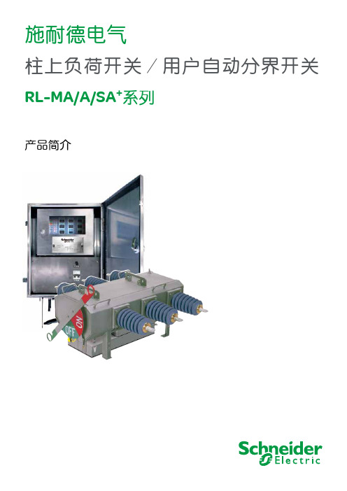
产品简介柱上负荷开关/用户自动分界开关RL-MA/A/SA +系列施耐德电气前言RL-MA/A/SA+系列我们的目标为我们的用户和全社会提供先进的中压架空线路系统自动化、保护以及控制系统设备。
我们的柱上产品家族包括:●RL系列SF6气体绝缘三相负荷开关/用户自动分界开关●U系列固体绝缘三相真空自动重合器●N系列SF6气体绝缘三相真空自动重合器●PTCC系列柱上通讯控制器●ADVC系列柱上通讯控制器●ESC100用户自动分界开关控制器今天的电力用户希望尽量减少停电和降低运行成本。
为了使您未来的配电系统更具竞争力,施耐德电气坚持不懈地致力于向您提供在未来更具竞争性的最先进的配电设备。
过去,用户仅仅是为了满足负荷增加的需要而购买负荷开关等配电设备。
今天,应用这种高新技术设备,并综合对已有配电系统更完善的管理,即可实现提高供电可靠性的前提下降低运行成本并增加投资回报率。
介绍和应用介绍 (7)开关的基本运行操作 (7)开关用作自动分段器运行 (8)开关用作用户自动分界开关运行 (8)产品优点模块化设计 (9)先进绝缘技术 (9)内置电流、电压传感器 (9)低气压闭锁 (9)远程控制和监控 (9)减少安装成本 (9)减少操作成本 (9)增加收益 (9)延缓基本建设工程项目再投资 (10)用户信赖 (10)无障碍通讯 (10)开关描述开关触头 (11)操作机构 (11)外壳 (11)指示器 (11)电流互感器 (11)电压传感器 (12)操作 (12)电路 (12)测量功能相过流故障检测 (13)单相接地故障检测 (13)浪涌抑制 (13)自动分段功能 (13)供电中断 (13)顺序复归时间 (13)电压 (14)电流 (14)有功功率(单方向流量或总流量) (14)功率因数 (14)测量值历史数据 (14)历史事件 (14)气体压力测量 (14)ESC100柱上控制器相间故障过流分闸功能 (15)零序电流分闸/报警功能 (15)失压报警功能 (15)功能与特点 (15)指示灯功能说明 (15)RL-PLC 掌上可编程控制器设置投切 (16)蓄电池电源开关 (16)按键功能说明 (16)本地遥控功能说明 (16)ESC100控制器的特点 (16)结构特点 (16)ESC100控制器与开关及电源PT的连接控制器与开关通过航插连接 (17)控制器与电源PT的连接 (17)控制器单(双)电源PT的连接 (18)ESC100控制器的通讯功能 (18)通用信息RL系列负荷开关/自动分段器电气参数 (19)ESC100控制器技术参数 (19)ESC100控制器外形尺寸 (19)ESC100控制器重量 (19)ESC100控制器使用环境 (18)柱上安装细节柱上安装细节 (21)ESC100控制器安装尺寸 (22)订货信息负荷开关/自动分段器 (23)附录ESC100控制器码盘定值设定.......................................................................24-26 RL-PLC 掌上可编程控制器的遥控 ...............................................................27-28 ESC100控制器GSM/GPRS通讯设定...........................................................29-35施耐德电气RL-MA/A/SA+系列柱上SF6气体绝缘用户自动分界开关具备手动和自动两种操作方式。
- 1、下载文档前请自行甄别文档内容的完整性,平台不提供额外的编辑、内容补充、找答案等附加服务。
- 2、"仅部分预览"的文档,不可在线预览部分如存在完整性等问题,可反馈申请退款(可完整预览的文档不适用该条件!)。
- 3、如文档侵犯您的权益,请联系客服反馈,我们会尽快为您处理(人工客服工作时间:9:00-18:30)。
施耐德a型控制器说明书
、万能式断路器结构概述
要是该断路器是采用了框架式设计的且以空气为介质的断路器,通常可分为固定式或者是抽屉式两种结构。
一般万能式断路器固定式是在本体的两侧位置上安装侧板组成,而抽屉式则是将题本装入到专用的抽屉座上组成。
万能式断路器的本体结构是由操作机构、触头系统、灭弧机构、辅助开关、电流互感器、智能脱扣器,以及二次插接件、失压和分励脱扣器等零部件组成,整体来讲万能式断路器结构是采用了立体布置形式做到了更紧凑和体积小的特点。
二、万能式断路器结构特点
首先断路器的触头部分是全部的封闭到了一个绝缘框内,同时每相的触头还要利用绝缘板将其隔离开来,这样可以形成一个小室确保安全。
再有就是智能脱扣器、手动与电动操作机构一次的排在触头系统的前面,从而形成各自的单独空间模块,有利于日后在检修或是维护的过程中拆卸会更加的方便。
三、万能式断路器结构图示
A、断路器正面结构图示(其中包含各个部件名称说明)
万能式断路器结构组成和接线图一
1、二次回路接线柱;
2、抽架;
3、故障跳闸指示/复位按钮;
4、“分闸”锁定;
5、储能手柄;
6、合闸按钮I;
7、分闸按钮O;
8、储能指示;9、主触头位置指示;10、智能型脱扣器;
11、摇柄及其存放处;12、运行、试验和退出位置指示;
13、摇柄插入位置;14、运行、退出、试验位置锁定的挂锁位置;
15、运行、退出和试验位置的锁定装置;
16、运行、退出和试验位置的锁扣解扣。
B、断路器内部结构图示(其中包含各个部件名称说明)
万能式断路器结构组成和接线图二
1、下母线;
2、互感器;
3、动触头;
4、上母线(静触头);
5、静触头引弧片;
6、断路器底板;
7、灭弧罩;
8、断路器基座;
9、欠压、分励脱扣器;10、闭合脱扣器;11、主轴;12、操作机构;
13、面罩;14、机构储能弹簧。
四、万能式断路器触头系统结构
断路器的每相触头系统基本上都是将其安装到是采用绝缘体构
成的小室当中,同时在它的上方位置有灭弧室。
而触头则是利用连杆和绝缘体外的主轴进行连接,这样就能够完成万能式断路器的闭合、断开的工作。
为了能够让每相的触头系统可以有效的减少电动斥力,这里还采用了十档、十四档两种触头并联形式,将触头安装到一个触头的支撑上。
并且触头的一端位置用软联结和母排相互连接,当万能式断路器在执行闭合动作的时候,这时主轴会带动连杆使得触头支撑绕O点逆时针旋转。
在动静两个触点完成接触动作后压缩弹簧会产生足够的触头压力,实现断路器能够可靠的接通。