国外渔业文摘不规则波浪中的重力网箱流体动力学性状的数值模拟
不规则波和流下的重力式网箱水弹性响应研究

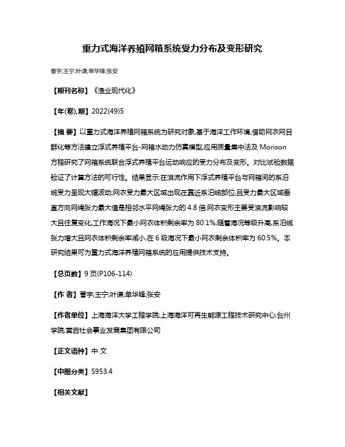
第22卷第3期 2018年3月船舶力学Journal of Ship MechanicsVol.22 No.3Mar. 2018Article ID:1007-7294(2018)03-0260-16Hydroelasitic Analysis of the Gravity Cage Subjected toIrregular Waves and CurrentHU K e1,2, FU S h i-x ia o1,2(1. State Key Laboratory of Ocean Engineering, Shanghai Jiao Tong University, Shanghai 200240, China;2. Collaborative Innovation Center for Advanced Ship and Deep-Sea Exploration, Shanghai 200240, China)Abstract: In this paper, the hydroelastic response of a gravity cage exposed to irregular waves and current was analyzed. A full scale net cage bulit by the FEM was introduced to further study the cag e's motion and deformation. In the numerical model, nonlinear spring elements and truss elements were used to simulate the mooring lines and the net, respectively. Furthermore, the 耶 buoyancy distribution' method was adopted by simulating the floating collar with several coupled beams in order to calculate the instantaneous buoyancy force acting on the collar. On this basis, when the net cage is subjected to wave-current flows, the dynamic response of the floating collar, the modal contribution to the collar's deformation from each mode shape were carefully studied. The results show that more flexible modes will be aroused in the vertical direction when the significant wave height increases;while the current will have a great contribution to the rigid-body motion in the horizontal direction.Key words: gravity net cage; finite element analysis; irregular waves and current flow;hydroelastic responseCLC number: O357 Document code: A doi: 10.3969/j.issn.1007-7294.2018.03.0020 IntroductionThe offshore environmental problem is becoming a crucial issue for human society and the development of the nearshore aquaculture industry. Moreover, the demand for more sea foods high in protein is pushing engineers to design cost-effective fish cages that can withstand extreme environmental loads in deeper ocean conditions. Therefore, accurate prediction of a cage 爷 s hydroelastic response has become a key focus in aquaculture engineering.Previous investigations into sea loads on gravity net cages normally considered the impact of waves and currents separately.First of all, the investigations into the wave loads exerted on the net cages focused on three main aspects:the loads on the net, the loads on the collar and the dynamic response of the fishReceived date:2017-12-07Foundation item: Supportted by the National Natural Science Foundation of China (Grant No. 51279101, 51490674 and 51490675); National Basic Research Program of China (973 Program-2013CB036103); the High-TechShip Research Projects of the Ministry of Industry and Information Technology (special topic: Mooringpositioning technology research of floating structures)Biography:HU K e(1986-), male, Ph. D., student of Shanghai Jiao Tong University;FU Shi-xiao(1976-), male, professor, corresponding author, E-m ail: shixiao.fu@.第3期HU Ke et al: Hydroelasitic Analysis of the Gravity Cage 噎261cage system.Concerning wave loads on the net, Lader[1]compared the changes in the wave height and energy before and after the wave passed through the net. Song[2]successfully predicted wave loads of the net by calculating the cubic net cage?s hydrodynamic response based on sinusoidal wave theory and the Morison equation, and he claimed that the relative error between the numerical prediction and test result was under 15%. Ito[3-4]simplified the wave condition into- forms of oscillating flow, under which the hydrodynamic forces on the net with different solidity ratios and pretensioning forces were studied.In order to conduct detailed research into the wave loads on the collar, Krassimi[5]calculated the damping coefficient and added mass coefficient for the forced oscillating collar based on the potential flow theory. Kristiansen[6]later conducted a model test in a wave tank with a cylinder fixed on the free surface. He further investigated the nonlinearities in the wave forces on the collar caused by the influence of the free surface.To quantify the response of the fish cage, Colbourne[7]conducted an experiment on multiple cages to compare the mooring forces under different kinds of wave loads. Fredriksson[8]and Fredriksson, et al[9-10]carried out a serious of experiments to investigate the mooring line forces and motion of the realistic fish cage. Besides, numerical simulations were also performed, and comparisons between experimental and simulated results indicated good agreements. By using the lumped mass point method and rigid body kinematics theory, Dong[11]and Xu[12]predicted the response of a net cage under irregular wave loads.Secondly, in the case with current only (no waves), Aarnses[13]studied the drag force on the net cage, the changes in the cage?s volume and the reduction in current speed by towing a gravity cage model in calm water. Lader[14]conducted an experiment with a full-scale cage to specifically study the relationship between the current speed and cage 爷 s volume. Huang[15]and Zhao[16-17]studied the hydrodynamic response based on the 耶 lumped mass point method 爷.Huang found that the total force of the numerical model was lower than the experimental data when the Reynolds number was lower than the range of 1400-1800, while Zhao noticed that the volume of a net cage with diamond grids was larger than that with square grids. Berstad[18]calculated the mooring forces and the volume changes of a net cage by using finite element software (AquaSim). Moe[19]used ABAQUS to analyze the deformation of the net cage in currents with different speeds. Kristiansen[20]estimated the drag force and the volume changes of a net cage by replacing the twine5s drag and lift forces with each plane5s tangential forces and normal forces. The numerical results were in good agreement with the experimental data.Based on the previous study, the hydrodynamics of the fish cage under wave or current loads has been researched extensively. Because irregular waves and currents normally co-exist in the real ocean environment, the dynamic response of the gravity net cage under the combined effects of irregular waves and currents needs to be further studied. Besides, because geometric nonlinearity due to net cage?s large deformation under the wave-current loads is evident, research on the full scale model should be conducted.262船舶力学第22卷第3期In this paper, a full-scale numerical model of a gravity net cage under irregular waves and currents was studied by using FEM. The irregular waves were simulated based on the JON- SWAP wave spectrum. On this basis, the dynamic response of the floating collar, the modal contribution from each mode shape to the collar in the combined wave-current flows together and the changes in the mooring-line tension were analyzed.1 Basic theory1.1 Equations of motionWhen the whole gravity cage is exposed to irregular waves and current, the dynamic equilibrium equations of the structure can be expressed as:[m][蓘]+ [c] [x] + [k] [x]=F(1)e x tF=G+f b+f w+f c(2) where 蓘m蓡is the mass matrix,蓘c蓡is the damping matrix and 蓘k蓡is the stiffness matrix of thee x tsystem. The total external loads on the structure represented by F include four parts, which are the gravity force G, the buoyancy force fb,the wave forces fw and and the current forces f c. In Eq.(1) and Eq.(2), the gravity force G can be calculated by the static buoyancy force. The buoyancy force fb is calculated according to the volume of water displaced by the structure, and will be described further in Chapter 3.Both the wave forces f and the current forces f can be estimated by the modified Mori-w cson equation[21], where the velocity of the current and wave is superposed linearly, as shown in Eq.(3),F=fw+fc =C d\p D\U-Vp±U\〈U-Vp±U+C M P:4D u-C m P:4D a p⑶where C m represents the inertia coefficient, CM=Cm+1, C d is the drag coefficient, D is the effective diameter of the beam elements and the truss elements, u and u represent velocity and acceleration of water particles in the wave-only condition. U is the current velocity and p is the water density. In the dynamic analysis where the motion of the structure must be taken into account, Vp and Up represent the velocity and acceleration of an element forming the structure. In this case, the influence of the mutual interference of the velocity field in the combined wave- current condition is not considered, see Lee[22]. Based on the equation, the dynamic reponse of the net cage will be studied under wave-current combined condition, and the results will be further compared against those in wave-only condition.1.2 Description of irregular wavesSeveral linear waves with random phase angles can be combined to generate an irregular wave.Firstly, the elevation of water surface in an irregular wave can be written as:第3期HU Ke et al: Hydroelasitic Analysis of the Gravity Cage 噎263浊(x, z, t )=移 A n sin (k nx -M nt+£n )(4)n=1while the horizontal and vertical velocities of a water particle can be expressed as:U ( x, z , t 蔀=移 A n 棕 n cosh^ ^ sin ( k n x -棕 n t+着 n 蔀 (5)n =1 sinh(k nd )肄 T sinh (k n (z+d 蔀)W ( X , Z , t 蔀=^An 棕 n —• A t i +、 c o s ( k n X -棕 n t +着 n 蔀 (6)n =1 sinh (k n d )where A can be further denoted as:nA n =姨2S 浊(棕)驻棕 (7)In the four equations above, A n , k n , ^n and 棕n represent the wave amplitude, the wave number, the random phase angle and the circular frequency of the nth regular wave component, repective-ly. z is the vertical position of a water particle, d is thedepth of the water, S 浊(棕)is the wave spectrum and驻棕 denotes the difference between the circular frequencies of the measured components. The irregular wavewas formed by choosing appropriate input parametersbased on the JONSWAP wave spectrum, moreover, thesignificant wave height defined as the mean of the one Fig.1 JONSWAP wave spectrum with different significant wave heightthird highest waves (H "3 ) and the mean wave period (T j in this paper were chosen a s 3m and 5 s, respectively. The corresponding wave spectrum is shown in Fig.1.Based on the wave spectrum presented above, the time series at point (0, 0, 0) is shown in Fig.2.1.3 Geometric nonlinearityAccording to the small deformationhypothesis, the strain in a certain directionat an arbitrary point can be derived by calculating the first-order partial derivativeof the corresponding displacement. Underthis hypothesis, the large deflection and rotation of the element can be ignored whenformulating the equilibrium. Nevertheless, due to the large deformation experienced by the structure, the geometric nonlinearities in the finite element analysis should be focused on in this study.1.3.1 Strain-displacement relationshipWhen geometric nonlinearities are considered, the relationship between the stress and the strain can be expressed as:Fig.2 Wave elevation time series at point (0, 0,0)264船舶力学第22卷第3期{着}=蓘]{啄}[軍j is a strain matrix, which can be further decomposed into:蓘 1 = [B0] + [B l](8)(9)where [B〇]isaconstan tstrain m atrix,and [B L j is the nonlinear strain matrix related to the displacement of the node considered.1.3.2 Stress-displacement relationshipThe relationship between the increment of stress and that of strain can be expressed as:d {滓r=[ d j d {着r(i〇) where [D j is the constitutive matrix for the material. Combining Eqs.(8)-(10) can lead to Eq.(11),d {滓r=蓘d蓡蓸蓘b〇蓡+蓘B l j) d {啄r(11)1.3.3 Equilibrium equationBased on the principle of virtual work,the equilibrium equation can be expressed as: |f e T e e T eJ{着*瑟{滓瑟d v-{啄*瑟{F}=0 (12)Ve e e where {着* 瑟and {滓瑟represent virtual strain and stress of an element,respectively. {啄* }eis the virtual nodal displacement and {F瑟represents the nodal forces.A combination of Eq.(8) and Eq.(12) results in,J蓘]V}e d v-{F}e=0 (13)VDifferentiating this equation can lead to,J d蓘j {滓} dv+ J 蓘]d{^} dv=d{F} (14)V VEq.(14) can be rewritten as:([k〇j + [k滓j + [kLj)d{啄瑟e=d{F瑟e(15) Eq.(15)isthebasisforsolvin ggeom etricnon lin earp roblem s.Inthisequ ation,[k〇j is a standard linear stiffness matrix,[k滓]is the initial-stress matrix for nonlinear conditions,and [&] is the initial displacement matrix under large deformation. The three matrices can be expressed as:[koj= J d[B0j[D j [B0j dv [k滓]d{滓瑟=J d[^j {滓瑟dv (16)(17)第3期HU Ke et al: Hydroelasitic Analysis of the Gravity Cage 噎265[kL ] = | ( [B0]T[D] [B l ] + [b /[D ] [B0] + [b /[D ] [B l ] )dv (18)V 1.4 Modal superposition methodIn order to have an overview of the motion and deformation of the system, it is important to study the global deformation of the floating collar at first. Even though it is impossible to use modal superposition method to predict the nonlinear hydrodynamic response of the floating collar, the method can still be considered as a 4data post-processing5 procedure. Based on the predicted nonlinear hydroelastic results, the method can be applied to analyze the weight of the participation of each mode at any instant.In this method, the hydrodynamic response of the floating collar can be described as a linear superposition of all the possible motion and deformation modes:肄w (t , x ')=移 Pi (t)渍;(x 蔀,x e 蓘 0, l 蓡i =1Replacing 肄 by n in Eq.(19) yields:nw (t, x 蔀=移Pi (t 蔀渍;(x 蔀,x e 蓘0, l 蓡i =1where p { (t ) represents the weight of the ith mode in the global response at time t and 渍i (x ) represents the ith-order mode shape. Eq.(20) can be further expressed in matrix form:蓘w 蓡(t)=蓘渍蓡[p 蓡(t) (21). . . T ...After multiplying both sides of Eq.(21) by [渍],the modal-weight matrix at time t canbe rewritten as:(19)(20)T -1 tL p ]u)=蓸渍][渍])[渍][w ]w Therefore, the standard deviation of the modal weight can be derived as follows:(22)03)where T is the total time length and Pi (t ) symbolizes the time-averaged modal weight.2 Finite element model descriptionsNumerical and experimental results in the previous work by Lader[14] and Berstad[18] have shown that the bottom nets normally have a negligible effect on the global dynamic response of fish cages. Therefore, in the finite element model, the bottom net and its knots were excluded. The numerical model of the whole gravity net cage is shown in Fig.3. The numerical model is composed of 4 main parts: the floating collar, containment net, mooring lines and bottom ring. To avoid unwanted friction caused by chains and ropes, the bottom ring is attached to the net directly, see Lader[23]. The original solidity of net panel is 0.32. The materialsused266船舶力学第22卷第3期and their relative properties are also listedin Tab.1. Due to the limitation of the computational capability, the mesh size of thenet is generally enlarged in order to reducethe computational time. The validation of thesimplified method is shown in the section 3.1. Four points on the floating collar (A, B,C and D), marked as chief indications forthe the dynamic response of the floatingcollar, will be further investigated in Chapter 3.Tab.1 Properties of fish cage systemDiameter of fish cage (m)20Depth of fish cage (m)20Floating collarsinker Net Outer diameter (m)0.30.10.05Thickness (m)0.02--Elastic modules (MPa)950950350• 3Density (kg/m )9532 0001 120To begin with, the collar and bottom ring were simulated by the beam elements. Considering the non-bending properties of net twines, the truss elements were adopted to simulate the twines.The instantaneous buoyancy acting on the collar often makes it difficult to calculate the hydrodynamic forces accurately. Therefore, the 耶Buoyancy Distribution5method, see Li[24], was adopted to solve this problem by replacing the partly immerged floating collar with 11 distributed coupled beams as shown in Fig.4.^^p istirib u ted coupled section扭41 1B s o i e 2B it 柳 3B e 拉M B e a n 5 B e a u G 7S (issri : S f g e d )Bean 9 fiaaQr*e:d)O f l &E L I (ia m g ru e d ]Fig.4 Illustration of the distributed coupled beam sectionThe instantaneous buoyancy of the whole section fB s e c t i 〇n equals the sum of the buoyancy of each immerged beam ( f B _i m m e r g e d _b e a m ) ^, which can be expressed as:Fig.3 The complete fish cage systemmodel第3期HU Ke et al: Hydroelasitic Analysis of the Gravity Cage 噎267fB_s e c t i o n移(f i m m e r g e d_b e(24) In order to ensure that the distributed beam sections move and deform simultaneously, the six degrees of freedom for each pair of nearby nodes on the neighbouring beams should satisfy the linear constraints.Meanwhile, the mass and bending-stiffness properties of the floating collar and the beams must also be equivalent, as described in the following equations:m s e c t i o n^m i05)(E I)se-=移E i l(26)where m section ™d (E/)sectio n arethemassdensity andthebending stiffnessofthesectioninthe floating collar, respectively, while m i and (E l)i are the mass density and the bending stiffness of the ith distributed beam.Secondly, in the simulation of the mooring lines, four spring elements with 6 000 N/m linear tensional stiffness, were employed. The spring elements were attached horizontally to the floating collar in the xoy plane in Fig.3.3 Results and discussionsABAQUS/Standard, a software for finite element analysis, was used to simulate the model under the combined effect of current and irregular waves. Both the wave load and the current load were calculated based on the Morison equations, the hydrodynamic coefficients C M and C d should be chosen according to the Re and K C numbers. In this paper, the R e number was pretty low and the K C number was very high, hence C m and Cd were chosen as 2.0 and 1.2, respectively^251. Moreover, the geometrical nonlinearities associated with the nets 爷large deformation and motion were also taken into account.3.1 Validation of the numerical modelOwing to the large number of meshes in a full-scale net, it is hard to conduct calculations on a model with detailed mesh. Thus, the full-scale model was simplified. The hydrodynamic force, tensile stiffness and mass in the simplified model should be equivalent in the numerical models before and after simplification. This can be described in the following equations:A t-= ^A k(27)(s e c t i o n. )t r u s s•^移E k A s e c t i o n_k08) M t r u s s=M(29)268船舶力学第22卷第3期where A and A are the proiected area and cross-sectional area of the twine; M is the mass sectionof the net, and E represents the elastic modulus. Moe[19]validated their numerical models by comparing predicted deformation to that of a real model. Similar deformation to that observed by Moe[19]was observed in this model. Moreover, the deformation of the model with detailed mesh agrees well with that of the simplified model. The comparison also indicates that the model with coarse mesh was sufficiently accurate to study the motion and deformation of the gravity cage. The result is shown in Fig.5.Comparison of models Companion ot modelswith dettiiled mesh with applied (coiiise) mesh(h i)Dctormaiion picdi.LH.-Ll(cJ) JJemrinanun,prcdicicdby Moc ct a J 12010)b y M oecU ili:2U]〇)(<l)Model E C.S I化戒T e L tiim(b2) DcJornialion predfcicd le i) Petomialion prcdicicdm ill i s s i u d v m ih is sti]d vFig.5 Validation and verification of the numerical model3.2 Modal analysis of floating collar under combined effects of irregular wavesand currentAs the modal superposition method mentioned in the section 1.4, the mode shapes of the 1st to the 20th modes of the floating collar calculated by the modal analysis were shown in Fig.6. The modes numbered from 1t o6correspond to the six rigid-body-motion modes, while the rest correspond to the flexural deformation modes of the structure. In this analysis, the nonlinearities in the mooring-line are ignored.第3期HU Ke et al: Hydroelasitic Analysis of the Gravity Cage 噎2690 Hz (Rigid-body mode,/>-9.54 «10* 'Hz (Rigid-body( Rigiii-hoiJy mode, vertical rotanon in plane ) mode, roll iti in pltme O'r-z)motion in the plane O-x-z)/&-3.1〇x l〇--Hz\\z(Rimd-hodw_/4-1.22^]r- Hz(Rigid-badv(Kiyiu-bodv mcxie.mode, trai]sial[omn the planeH id e, roll m the plane O-.t-j)transJatiomn the planeO-x-v)J7 =0.55213 Ilz/s =0,552 13 H/.(Flexural mode in U’lexuraJ mode i n sitk(He s ury I mode iji(Hm jrd mode in O-.^-r view)view)O-x-z view)yidtr view)/g =0.569 25 Ux/,〇 =0,571 95 Hz/,i=].584 4Hz(Flexunil rm)de m the iTIcxuml mode in the(Hcxural mode in(J Jcxuial m odea tlL-plane O'x-y)O-x-z view)e ii side view)Fig.6 shows that the deformation of the 1st, 5th, 6th, 9th, 10th, 13th, 14th, 17th and 18th modes appears in the O -x -y plane, while that of the 2nd, 3rd, 4th, 7th, 8th, 11th, 12th, 15th, 16th, 19th and 20th modes occurs in the O-x-z plane in Fig.3.In order to investigate the modal contribution, the numerical model operated in conditions where the current speed was set as0m/s, 0.5 m /s and 1m/s, coupled with i^egular waves with /『]=1.584 4 Hz yij = !.ftll 2 Hz fu = l£i \ 2llz\ /t 〇k ' / / 飞咖 r '!K i / \'I .丨一':'1^s.J \ ■ll}:■(Flexural mode inO-x-z view)(Flexural mode in side view)(Flexuralmode in the plane (l lcxural mode in tlic plane C i-.v -v )057 2 11/./ifi^3.057 2 Hz■_ r】node h iP-.v-z view)(Flexural mode h i side view)(Fkxural mode in view)(Flexural mode in side view)/7-3.0S 9 7IIZ H O W 3 M z /a ,=4,961 4 Hz (〕(Klexunil mode in the plane O-r-v)(Flexural mode in the pfane O 'w )(Flexural mode in O u view)(Flexural mode in side view)/m =4.961 4 Hz ,,jL //\^Y '■n .(FlexuraJ mode in O-r-j view)(HeKural mode in side view)Fig .6 The first 20 mode shapes of the floating collarsignificant heights set as 0.3 m,1m and 3 m. Time histories of the modal weight in the horizontal and vertical directions are shown in the figures below (Figs.7-16), and their corresponding standard deviations are depicted in the four following figures (Figs.17-20): Analysis of modal weights in the horizontal response revealed that the 5th, 6th, 9th and 14th modes were the dominant modes. This means that the translational rigid-body-motion modes as well as the in-plane flexural structural-deformation modes dominated the response of the floating collar. However, as the current speed increased, the modal weights of the 5th and 6th modes experienced a steeper increase than the flexural structural-deformation modes, indicating that the current had a stronger influence on the translational rigid-body-motion modes.电 〇&0 90 10G M s)Fig.16 Modal weight (vertical motion when H 1/3=3 m, Tx =5 s, C=1.0 m/s)Fig.14 Modal weight (vertical motion when H 1/3=3 m, T 1=5 s, C=0.5 m/s)Fig.15 Modal weight (horizontal motion whenH "3=3m , (=5s ,C=1.0m /s)Fig.17 Standard deviation of the horizontal response of each mode for different significant wave heightsWith regard to the vertical response, the 2nd, 3rd, 4th and 8th modes participated most actively, as can be observed in Figs.8, 10, 12, 14 and 16. Each modal weight increased with the significant wave height. On the other hand, Figs.12, 14, and 16 show that the current had a smaller influence on the modal weight in the vertical direction compared to that in the horizontal direction.7C 孩分 90 1Q 〇Modal weight (horizontal motion whenH "3=3m , T !=5s, C=0.5m/s)-s js l -ll ft fxs:l l f .^^n lopos1]Mode nymberFig.18 Standard deviation of the horizontal response of each mode for different current speedsFig.19 Standard deviation of the vertical response of each mode for different significant wave heightsFig.20 Standard deviation of the vertical response of each mode for different current speedsBesides, the comparison of the horizontal and vertical standard deviations of each mode above shows that much higher modes (flexural structural deformation modes) were excited vertically. The current had a stronger impact on the standard deviation of the 5th and 6th modes in the horizontal direction. In addition, the standard deviation of modal weight increased with significant wave height in both directions, which indicates that higher waves may induce higher l t o p fi >3p-H EPUE^order modes.From the discussion in this section, it can be seen that compared with the wave-only-condition, the combination of current and wave has a greater influence on the translational rigid- body-motion in the horizontal direction. This indicates that the rigid-body motion of the floating collar should be paid more attention in the design of mooring systems attached to the fish cage in the wave and current combined condition. It has also been suggested that higher wave will arouse more flexible modes, while current contributes little to the flexible modes.4 ConclusionsThis paper presents an analysis based on the FEM in predicting the dynamic response of the gravity net cage system under the combined effects of irregular waves and current. The following conclusions are derived: the modal weight in both the horizontal and vertical directions becomes larger as the significant wave height increases, which can be found from the modal analysis of the floating collar under the combination of irregular wave and current. Meanwhile, the modal weight of the rigid-body-motion mode in the horizontal direction grows with the current speed, while the modal weight in the vertical direction is only slightly in^uenced by the variation of the speed. Moreover, it can be seen from the standard deviation of modal weight that much higher order modes will be excited with significant wave height increased. This indicates that when analyzing the total dynamic response under larger wave height, more attention should be paid on deformation.References[1] Lader P F, Olsen A, Jensen A, Sveen J K, Fredheim A, Enerhaug B. Experimental investigation of the interaction between waves and net structures-damping mechanism[J]. Aquacultural Engineering, 2007, 37(2): 100-114.[2] Song W H, Liang Z L, Zhao F F, Huang L Y, Zhu L X. Approximate calculated on waving-force for a square sea-cagehydrodynamics[J]. J Zhejiang Ocean Univ., 2003, 23: 211-220. (in Chinese)[3] Ito S, Kinoshita T, Kitazawa D, Bao W, Itakura H, Nishizawa S. Experimental investigation and numerical modeling of hydrodynamic force characteristics of a heaving net[C]. ASME, 2010.[4] Ito S, Kinoshita T, Kitazawa D, Bao W, Itakura H. Experimental investigation and numerical modeling of hydrodynamicforce characteristics and deformation of an elastic net[C]. ASME, 2011.[5] Krassimi I, Doynov. A dynamic response model for free floating horizontal cylinders subjected to waves[D]. Doctoral dissertation, University of Florida, 1998.[6] Kristiansen David. Wave induced effects on floaters of aquaculture plants[D]. Doctoral dissertation, Dept. of Marine Hydrodynamics, Norwegian Institute of Technology, 2012.[7] Colbourne D B, Allen J H. Observations on motions and loads in aquaculture cages from full scale and model scale mea-surements[J]. Aquacultural Engineering, 2001, 24(2): 129-148.[8] Fredriksson D W. Open ocean fish cage and mooring system dynamics[D]. Dept. Mechanical and Ocean Engineering, University of New Hampshire, 2001.[9] Fredriksson D W, Swift M R, Irish J D, Tsukrov I, Celikkol B. Fish cage and mooring system dynamics using physical andnumerical models with field measurements[J]. Aquacultural Engineering, 2003, 27: 117-46.[10] Fredriksson D W, DeCewa J, Swift M R, Tsukrov I, Chambers M D, Celikkol B. The design and analysis of a four-cagegrid mooring for open ocean aquaculture[J]. Aquacultural Engineering, 2004, 32: 77-94.。
波流作用下深水网箱受力及运动变形的数值模拟

波流作用下深水网箱受力及运动变形的数值模拟黄小华;郭根喜;胡昱;陶启友;张小明【期刊名称】《中国水产科学》【年(卷),期】2011(018)002【摘要】This study is aimed to discuss the effects of waves combined with currents on forces and motion deformation of deep-water net cages, and provides a strong reference to risk assessment for net-cage aquaculture with severe marine conditions. The set value of wave and current elements were as follows: wave heights H=4-6 m,wave periods T=6.0-8.6s, current velocities U=0.3-0.9 m/s. With a numerical model previously validated by physical model tests, the mooring line forces, the wave-current forces, the volume reduction rate and the floating-collar pitches of the deep-water net cage were calculated. The simulated results indicated that the mooring line force, the wave-current force and the volume reduction rate were all in direct proportion to wave height as well as current velocity, but less related to wave period. Furthermore, the wave-current force on the cage was approximately equal to the sum of force on each mooring line on wave-side. The volume reduction rate reached 47%-56% for the cage caused by the conditions of wave height of 4-6 m and current velocity of 0.75m/s, which showed serious cage deformation. Therefore, we concluded that farming sites should not be placed in sea areas where current speed exceeded 0.75 m/s. The calculated results also showed that the influenceof wave period on volume reduction rate was slight, while significant on the floating-collar pitch. The floating-collar pitch would decrease as wave period increasing at constant wave height and current velocity.%基于已建立的浮架和网衣数学模型,对不同波况和流速共同作用条件下HDPE深水网箱所受的锚绳力、波流力、容积损失率以及浮架倾角进行数值计算,设计的波流要素值为:波高H=4~6 m,周期T=6.0~8.6 s,流速U=0.3~0.9 m/s.结果表明,网箱锚绳受力、波流力和容积损失率均与波高和流速成正比,与周期的关系不明显,且网箱系统所受的波流力约为网箱迎浪侧两根锚绳受力的合力.在波高H=4~6 m、流速U=0.75 m/s时,网箱容积损失率达到47%~56%,网箱变形较为严重,为此建议网箱养殖区域应选择流速小于0.75 m/s的海区较为适宜.周期对网箱容积损失率的影响很小,对浮架倾角的影响较为明显,波高和流速不变时,随着周期的增大,浮架倾角会有所减小.本研究旨在探讨波浪流对深水网箱受力及运动变形的影响,为高海况网箱养殖的风险评估提供参考依据.【总页数】8页(P443-450)【作者】黄小华;郭根喜;胡昱;陶启友;张小明【作者单位】中国水产科学研究院,南海水产研究所,广东,广州,510300;中国水产科学研究院,南海水产研究所,广东,广州,510300;中国水产科学研究院,南海水产研究所,广东,广州,510300;中国水产科学研究院,南海水产研究所,广东,广州,510300;中国水产科学研究院,南海水产研究所,广东,广州,510300【正文语种】中文【中图分类】S95【相关文献】1.波流作用下圆形重力网箱锚绳受力分析的理论模型 [J], 杜健航;何真;鄢奉林;李志强;王筱珍;俞国燕;刘璨;王贵2.不规则波流作用下斜桩上受力系数的确定方法 [J], 滕斌;李玉成3.平面网衣在水流作用下的受力和变形特性数值模拟研究 [J], 黄小华;郭根喜;陶启友;胡昱4.波流共同作用下潜丁坝受力情况的二维数值研究 [J], 罗兰媛;郭杰5.波流联合作用下承台结构受力研究 [J], 田恒葵因版权原因,仅展示原文概要,查看原文内容请购买。
鱼类波状摆动推进的数值模拟

鱼类波状摆动推进的数值模拟
鱼类波状摆动推进是一种推进技术,它利用鱼类的波状摆动来推动船只前进。
它的原理是,当船只沿着水面前进时,它会产生一系列的波状摆动,这些波状摆动会产生一种推动力,使船只前进。
要进行鱼类波状摆动推进的数值模拟,首先需要建立一个模型,模拟船只的波状摆动。
这个模型可以使用多种方法来建立,比如使用流体力学方法,使用有限元方法,或者使用经典的潮流方程。
接下来,需要计算船只的推进力。
这可以通过计算船只的波状摆动产生的力来实现。
这些力可以通过计算船只的波状摆动产生的水动力来计算,也可以通过计算船只的波状摆动产生的抗力来计算。
最后,需要计算船只的推进效率。
这可以通过计算船只的推进力与船只的总重量之比来实现。
通过上述步骤,可以完成鱼类波状摆动推进的数值模拟。
重力式海洋养殖网箱系统受力分布及变形研究
重力式海洋养殖网箱系统受力分布及变形研究
曹宇;王宁;叶谦;单华锋;张安
【期刊名称】《渔业现代化》
【年(卷),期】2022(49)5
【摘要】以重力式海洋养殖网箱系统为研究对象,基于海洋工作环境,借助网衣网目群化等方法建立浮式养殖平台-网箱水动力仿真模型,应用质量集中法及Morison 方程研究了网箱系统联合浮式养殖平台运动响应的受力分布及变形。
对比试验数据验证了计算方法的可行性。
结果显示:在浪流作用下浮式养殖平台与网箱间的系泊缆受力呈现大幅波动;网衣受力最大区域出现在靠近系泊缆部位,且受力最大区域垂直方向网绳张力最大值是相邻水平网绳张力的4.8倍;网衣变形主要受浪流影响较大且往复变化,工作海况下最小网衣体积剩余率为80.1%;随着海况等级升高,系泊缆张力增大且网衣体积剩余率减小,在6级海况下最小网衣剩余体积率为60.5%。
本研究结果可为重力式海洋养殖网箱系统的应用提供技术支持。
【总页数】9页(P106-114)
【作者】曹宇;王宁;叶谦;单华锋;张安
【作者单位】上海海洋大学工程学院;上海海洋可再生能源工程技术研究中心;台州学院;黄岩社会事业发展集团有限公司
【正文语种】中文
【中图分类】S953.4
【相关文献】
1.新型海洋养殖网箱系统的研究与应用
2.HDPE圆形重力式网箱受力变形特性的数值模拟
3.HDPE圆形重力式网箱受力变形特性的数值模拟
4.给重力式网箱配置分布式底部沉重或刚性沉框以降低容积变形
5.圆形重力式网箱锚碇系统的受力研究
因版权原因,仅展示原文概要,查看原文内容请购买。
波流作用下深水网箱受力及运动变形的数值模拟

中国水产科学 2011年3月, 18(2): 443-450 Journal of Fishery Sciences of China研究论文收稿日期: 2010-06-17; 修订日期: 2010-08-12.基金项目: 国家863计划资助项目(2006AA100302, 2010AA100301); 国家科技支撑计划资助项目(2006BAD09A14); 广东省海洋渔业科技推广专项资助项目(A200899G02, A200901G03); 中央级公益性科研院所基本科研业务费专项资助项目(2010YD09).作者简介: 黄小华(1982-), 男, 助理研究员, 从事渔业设施工程技术研究. E-mail: huangx-hua@ 通讯作者: 郭根喜, 研究员. E-mail: scsggx@DOI: 10.3724/SP.J.1118.2011.0443波流作用下深水网箱受力及运动变形的数值模拟黄小华, 郭根喜, 胡昱, 陶启友, 张小明中国水产科学研究院 南海水产研究所, 广东 广州 510300摘要: 基于已建立的浮架和网衣数学模型, 对不同波况和流速共同作用条件下HDPE 深水网箱所受的锚绳力、波流力、容积损失率以及浮架倾角进行数值计算, 设计的波流要素值为: 波高H=4~6 m, 周期T=6.0~8.6 s, 流速U=0.3~0.9 m/s 。
结果表明, 网箱锚绳受力、波流力和容积损失率均与波高和流速成正比, 与周期的关系不明显, 且网箱系统所受的波流力约为网箱迎浪侧两根锚绳受力的合力。
在波高H=4~6 m 、流速U=0.75 m/s 时, 网箱容积损失率达到47%~56%, 网箱变形较为严重, 为此建议网箱养殖区域应选择流速小于0.75 m/s 的海区较为适宜。
周期对网箱容积损失率的影响很小, 对浮架倾角的影响较为明显, 波高和流速不变时, 随着周期的增大, 浮架倾角会有所减小。
本研究旨在探讨波浪流对深水网箱受力及运动变形的影响, 为高海况网箱养殖的风险评估提供参考依据。
波流入射方向对网格式锚碇网箱水动力特性的影响
(1)
式中:Mi 为第 i 个集中质量点的质量;a为集中质量 点的加速度;Ti j为与 i 点相邻的 j 点之间的张力;FD 为集中质量所受波流作用的速度力;FI为集中质量 所受波流作用的惯性力;B为集中质量点所受的浮 力;W为集中质量点所受的重力。
锚碇系统主要由锚绳组成,和网衣类似采用集
中质量的方法将锚绳离散为若干个构件与集中质量
点进行分析。集中质量点位于构件的两端,通过将
构件所受外力均分到质量点上来获得各质点的受
力。图 3 为某一锚绳第 i 个集中质量点受力示意图,
图中 Tj、Tj-1、Wj、Wj-1、FBj、FBj-1、FDj、FDj-1、FIj、FIj-1 分 别代表与 i 节点左右相连的第 j、j-1 构件所受的锚绳
第4期
陈昌平等:波流入射方向对网格式锚碇网箱水动力特性的影响
831
2 计算模型的验证
利用物理模型试验对本研究中数学模型对于结 算波流作用下重力式网箱水动力特性结果的正确性 进行验证。该物理模型试验在大连理工大学海岸和 近海工程国家重点实验室多功能水池(长 56 m,宽
34 m,深 1 m)中进行,试验网箱模型根据重力相似准 则 [23],按照 1∶40 的模型比尺设计。图 5 为物理模型 试验中网箱模型的布置情况。水流方向与波传播方 向一致。模型验证时考虑正向入射情况,即图 5(a) 中所示的波流方向 1。
重力式深水网箱的抗台设计与水动力性能分析
第50卷第1期2021年2月船海工程SHIP&OCEAN ENGINEERINGVol.50No.1Feb.2021DOI:10.3963/j.issn.1671-953.2021.01.021重力式深水网箱的抗台设计与水动力性能分析郭帅,郭建廷,卞向前(江苏科技大学船舶与海洋工程学院,江苏镇江212003)摘要:针对重力式深水网箱抗台风能力较弱,容易出现浮架损坏、锚绳断裂和网衣严重变形等问题,以一典型重力式深水网箱为研究对象,结合传统网格式系泊,提出在底部附加系泊缆的新型抗台设计方案,基于势流理论和非线性有限元方法,建立网箱数值模型,在不同入射角和波高下,对比分析传统网格式和新型抗台式系泊的网箱系泊缆张力、浮架运动和网箱变形。
数值计算结果表明:与传统网格式系泊相比,新型抗台式系泊的网箱水平偏移平均减小7.81%,垂直下沉增加59.71%,系泊缆最大张力降低26.61%,网箱体积剩余系数增加超过70%,明显高于网箱容积的破坏阈值$关键词:重力式深水网箱;抗台设计;数值模拟;水动力性能中图分类号:U662文献标志码:A文章编号:1671-953(2021)01-086-5重力式深水网箱的结构形式简易、成本低廉、养殖容积大,操作使用方便,应用广泛,但因其较传统养殖网箱所在区域水更深,离岸更远,故容易受到台风灾害的破坏。
在台风作用下,重力式网箱常见破坏形式主要为浮架的损坏、网衣变形导致的容积严重损失及系泊缆的破断或走锚[1]$针对深水重力式网箱抗台风能力的研究,在规则与不规则波浪中进行网箱试验和数值模拟,开发网箱生存条件的数值计算工具[2]$针对南海台风下的恶劣海况,在重力式网箱的浮架上外接三角形框架,提出六三型单点系泊的网箱[3];针对网箱升降过程中易发生倾斜和变形的问题,利用圆周螺旋型浮管设计网箱升降系统,通过注水充气实现网箱下沉与上浮,使升降过程中浮管沿圆周方向受力均匀对称⑷。
关于网箱的水动力性能有基于有限元方法,结合网箱试验与数值计算,提出网箱系统动力响应分析方法[5];采用集中质量法和刚体运动学原理,研究波流逆向和同向作用下重力式网箱的水动力响应[6];采用数值模拟方法探究了3种系泊系统下锚绳张力变化规律,并设计制作1种传感器,完成了在台风天气下实地测量网箱锚绳张力的试验目前针对提升重力式网箱抗台能力的新型系泊设计研究有限,收稿日期:2020-04-01修回日期:2020-05-26第一作者:郭帅(1994*),男,硕士生研究方向:船舶与海洋结构物水动力分析为此,考虑以一典型重力式深水网箱为研究对象,结合统系泊,出附系泊缆的型抗台 方案,基于论和元方法,建立网箱数值模型,并对比分析在不同台风工况下统和型抗台系泊的系泊缆张力、运动和$1水动力学相关理论1.1网箱及系泊系统耦合运动控制方程采用全耦合时域分析法分析网箱及系泊系统的运动,其非线性运动控制方程[8]的时域形式为("S+"1)a($+(#+c H)a(t)++(r($)_$E(r($,r($)(1)式中:r为结构位移矢量;为结构质量矩阵;为水动力质量矩阵;#为结构阻尼矩阵;C H为水动力阻尼矩阵,+为结构刚度矩阵;$E为外力矢量。
网衣波浪水动力特性的数值模拟初步研究
的经验公式; 赵云鹏等 采用集 中质量法模拟 网
衣结 构 , 研 究 了圆形 重 力 式 网箱 的波 浪水 动 力 特 性; 詹 杰 民 等 分 析 了 网衣 受 力 与 流 速 、 冲 角 及
1 数值模型
1 . 1 控制 方程
本文数 值计 算 中, 流体 运 动 的控 制 方 程 采用
关键词 : 波浪 场 ; 多孔介 质模 型 ; 网衣 ; 波 浪 透 射 系数
d o i : 1 0 . 3 9 6 9 / j . i s s n . 1 0 0 7 - 9 5 8 0 . 2 0 1 3 . 0 2 . 0 1 1
中图 分 类 号 : P 7 5 2
文献标识码 : A
《 渔 业现 代化  ̄ 2 0 1 3年第 4 0卷第 2期
收稿 日期 : 2 0 1 3 - 0 1 — 1 1 修 回日期 : 2 0 1 3 - 0 3 — 1 7 基金项 目: 国家 自然科学基金重点项 目( 编号 5 1 2 3 9 0 0 2 ) ; 中央高校 基本科 研业务 费专项资 金资助 ( D U T 1 3 L K 5 5 ) ; 秦皇 岛市科技 项 目 ( 2 0 1 2 0 2 1 A1 1 3 ) 作者简介 : 赵云鹏( 1 9 8 0 一) 男, 博士 , 研究方向: 海洋牧场结构物水动力特性。E - ma i l : y p z h a o @d l u t . e d u o 1 3年第 4 0卷第 2期
重力式网箱群组系统耐流特性的数值模拟的开题报告
重力式网箱群组系统耐流特性的数值模拟的开题报告一、选题背景和研究意义近年来,水产养殖业快速发展,而传统养殖方式往往存在水质污染和饲料浪费等问题。
为了解决这些问题,人们开始探索新的养殖系统,其中重力式网箱群组系统是一种新型的养殖方式。
与传统养殖方式相比,重力式网箱群组系统具有水质稳定、养殖密度大、养殖周期短等优点,已经被广泛应用于养殖贝类、鱼类等水产生物。
然而,重力式网箱群组系统中存在各种因素,如潮流、风浪等,为了保证养殖环境的稳定,需要对其流体力学特性进行研究。
数值模拟是目前研究流体力学特性的常用方法之一,因此本文选择对重力式网箱群组系统进行数值模拟研究,探究其耐流特性。
二、研究内容和技术路线本文将以重力式网箱群组系统为研究对象,通过数值模拟的方法,研究其耐流特性。
具体研究内容包括:重力式网箱群组系统的流体场分析、网箱内外流场的对比分析、不同因素对网箱内的流场特性的影响等。
研究方法主要采用计算流体力学(CFD)软件进行数值模拟,通过建立网格模型和设置边界条件,对重力式网箱群组系统进行流场模拟,得出相关的流体力学参数,如速度、流量、压力等,从而研究其耐流特性。
技术路线如下:1.建立重力式网箱群组系统的三维模型,并进行网格划分和质量检测;2.设置边界条件,包括进口速度、出口压力、网箱材质等;3.运用CFD软件进行数值模拟,得出网箱内部和外部的流体场分布;4.分析模拟结果,获取重力式网箱群组系统的流体力学参数;5.通过对比分析,探究不同因素对网箱内流场特性的影响。
三、预期研究结果本研究通过数值模拟的方法,研究重力式网箱群组系统的耐流特性,得出相关的流体力学参数,并探究不同因素对网箱内的流场特性的影响。
预期研究结果包括:1.得出重力式网箱群组系统的流体场分布,研究其流体力学特性;2.分析模拟结果,得出重力式网箱群组系统的流体力学参数,如速度、流量、压力等;3.探究不同因素对重力式网箱群组系统内流场特性的影响;4.为重力式网箱群组系统的优化设计提供参考依据。
深水重力式网箱水动力特性数值模拟研究
深水重力式网箱水动力特性数值模拟研究由于近海海洋环境破坏严重,养殖区环境污染和病害问题日趋突出,导致养殖鱼类品质下降,死亡率不断增高。
为此,将网箱养殖业从内湾、近海向外海或深海发展已成为一种必然选择。
然而外海水域的海况复杂,深水区浪高、流急,网箱系统必须有抵抗大浪、强流的能力。
这也使深海网箱抗风浪和耐流技术的解决成为制约深水网箱养殖的主要技术瓶颈,而深水网箱水动力特性研究是解决这一技术瓶颈所必需的基础性研究。
本文采用集中质量方法和刚体运动学原理来建立数学模型,利用数值模拟的方法对重力式网箱在波浪、水流以及波流联合作用下的水动力特性进行系统研究。
以期依据计算机模拟结果,在一定程度上代替传统的模型试验和海上实际观测,以达到节省网箱设计费用,缩短设计周期的目的,从而为解决制约网箱发展的主要技术瓶颈提供工程理论和技术方法。
本文研究工作依托于国家自然科学基金项目和863计划合作项目。
研究论文共包含七部分:第一部分为绪论,主要介绍深水网箱养殖产业及相关学科研究的现状和进展。
第二部分为基本理论与数学模型的介绍,着重分析了重力式网箱主要组成部件数学模型的建立和整体网箱模拟计算流程,此部分是后面模拟工作的基础。
第三部对平面网衣系统在波浪、水流作用下的水动力特性进行了数值模拟研究,并利用模型试验结果对计算结果进行了验证。
第四部分对水流作用下整体网箱的水动力特性进行了模拟研究。
在物理模型试验验证的基础上,分析了配重系统,网衣网目形状和网筒形径高比对重力式网箱变形和受力的影响。
第五部分对单纯波浪作用下整体网箱的水动力特性进行了模拟研究,同时对网箱数值模拟中波浪理论的选择问题进行了讨论。
第六部分对波浪水流联合作用下整体网箱的水动力特性进行了数值模拟研究,并利用模型试验对计算结果进行了验证。
第七部分对重力式网箱下潜后的水动力特性进行了数值模拟研究,并分析了波浪作用下,下潜深度对网箱锚绳受力的影响。
在文章最后对本文取得的主要研究成果进行了总结,同时对今后网箱水动力研究发展进行了展望。
- 1、下载文档前请自行甄别文档内容的完整性,平台不提供额外的编辑、内容补充、找答案等附加服务。
- 2、"仅部分预览"的文档,不可在线预览部分如存在完整性等问题,可反馈申请退款(可完整预览的文档不适用该条件!)。
- 3、如文档侵犯您的权益,请联系客服反馈,我们会尽快为您处理(人工客服工作时间:9:00-18:30)。
响应 。数 值结 果显 示 随着 波浪 频率 的增 加锚 泊缆 受力 减小 。在低 频 率 情 况 下 , 网箱 的升 降 运 动 响 应 与 浪 高变化 同步 。
( A ueh rl n ier g V 14 I u ) 《 q au ua E g e n) o.2, s e n i ) s 2
的表 现 性 能 和 组 织 病 理 学 的 影 响
持续暴 露在二 氧 化碳 水 平 已在 升 高 的水 环境 中 , 密度养殖 的鱼类 就 会 与生 长 缓慢 、 理 性病 高 生
害和不 良健康 后果 等联 系在 一起 。虽 然 将水 泵 送
虾 提供 额外 的食 物 以及 可再 利用 的合 适 水质 。
建 了 三个 微 生物 垫 ( MA, MB和 MC) 。用 1 2天 大
向摆 放 的托 盘与增殖 托架上 的托盘之 间 , 牡蛎 壳 高
的变化 ( . 6 m / ) 有 明显 差 异 。这 表 明 以 1 0 0 m d 没
小 的南 美 白对 虾 后 期 幼 仔 ( L 2 以三 种 密度 进 P 1) 行放 养 。与 不 换 水 高 密 度 养殖 下 的对 照 组 相 比
( A u el rl n i eig V 14 I u ) ( q au ua E g er 》 o.2, s e2 ( t n n s
垂直布局 的牡蛎 养殖结构 装置 的 生 物 学 和 水 力 学 设 计
在本研究 中, 针对一 个具体 的垂直布 局牡蛎 养 殖 结构装 置 , 定 牡 蛎 的生 物 反 应 和 水 力设 计 技 确 术 。为 了评 估生物 反应 , 在~个 水深 3 5 I 且具 有 . l l
微 生 物 垫 对 水 质 及 南 美 白对 虾 后 期 幼 仔 表 现 性 能 的 影 响
在本 研究 中 , 用从 半 集 约 化 养 虾池 塘 中获 使
取 的微 生 物菌 株设 计并 构建 了微生 物垫 。依 据其 去 除无 机氮 的能 力 , 低 密 度 聚 酯 纤 维 上 分别 构 在
★ ★ ★
★ ★
《 渔业 现代 化} 00年第 3 21 7卷第 2期
7 3
( 进行 再 利 用 , 而 能 在 低 成 本 集 约 化 养 虾 系 N) 从
统, 尤其 是 在最 低换 水 或零换 水 养虾 系统 中 , 为幼
国 夕 渔 业 文 摘
再 循 环 养殖 系 统 中的 二 氧 化 碳 对 虹 鳟
代 表性 的区域 , 时九个 月测量 了以 0 5i 历 . n为水深 增 量沿水 深方 向摆 放 的托 盘 中牡 蛎 的生 长 率 。将 测量到 的牡蛎 生长 率 与放 置 在 附近 的牡 蛎增 殖 托 架( 水深 2 m) 的托盘 中的牡 蛎之生 长率 进行 比 上 较 。试验过 程 中 , 不 同深 度 的托 盘 中 , 在 或在 垂直
化碳溶解 浓度 ( / ) 8mg L 对虹 鳟 的表 现性 能 和健 康
¥ ¥ ¥ 羊 羊
模 型测试 。数值 模拟 结果 显示 出与试 验观 测值 良
好 的一致 性 。 随后 , 随机 相 位 方 法 造 出不 规则 按
波浪 场 , 接着 对 重力 网 箱在 不 规 则 波 浪 中 的流体 动力 学性 状进 行 模 拟 , 与其 在 规 则 波 浪 下 的结 并
米为最小深度 将托 盘沿垂直 方向摆 放 , 可有 效地利 用水 层来养 殖美洲牡 蛎 。为 了开发水 力设 计技术 , 使 用垂直 叠放 的一 叠 内装牡 蛎 壳 的托 盘进 行 了一 系列 真实条 件试 验 。有 了阻 力 和惯 性 力等 相关 力
较 , 生物 垫养 虾 显 示 出了 较 高 的将 氨转 化 成 亚 微
果进 行 比较 。应用 统 计方 法 和傅 里叶 变换 分析 了 网箱 在 时域 和频 域 中 的运 动 响应 和锚 泊缆 的张 力
的影 响。在试验研究 结束 时 , 两试验 组 的虹鳟 存活 率均较 高(> 7 ) 9 % 。在不 同的二 氧化碳浓度 之 间 , 没有观察 到生长 和存 活上有 明显差别 ( 0 0 ) P< .5 。
中, 皮肤及鱼 鳃类 病状 均 普 遍存 在 ; 于所 评 测 的 对 所 有组织类 型 , 两组 之间几乎 没有统 计学 上 的显著
差异 。研究结 果表 明 , 二氧 化碳 浓度 为 2 g L 在 4m /
的 WR S中将 虹 鳟饲 养 至 适 销 大 小 , 会 显 著 影 A 不 响虹 鳟 的总体 健康和 表现性 能。
硝 酸盐 和硝 态 氮 的氧化 能力 。整个 微生 物垫 中的
微 生物 量 , A + MB + MC可 证 明 虾 主动 啃 ∑M 食 摄取 微生 物 垫 中的物 质成 分 。这 些发 现可 以被
用 于对 在养 虾 生产 中从 微生 物 垫 中的原 生性 微 生
系数 的计算 结果 , 可为一牡蛎 养殖结 构装 置原 型 就
开 发 出一个 牡蛎装载 方案 。
( A uch rl n ier g V 14 ,I u ) ( q au ua E g ei > o.2 s e ( n n> s 2
物 的持 续 而 自给 自足 式 生 长 中产 生 的 额 外 的 氮
( A uel rl n i eig V 14 ,I u ) ( q au ua E g er ) o.2 s e2 t n n) s
不 规 则 波 浪 中 的重 力 网箱 流体 动 力 学 性 状 的数 值 模 拟
为 了解 当网箱处 于 高负 载 的波浪 和 海流情 况
下 的状 态性 能 , 用 数 值 方 法 系 统性 地 分 析 重 力 采 网箱 在 波浪 中的流体 动 力学性 状 。使 用质 量集 中 法 和 刚性 体 运 动学 原 理 , 过 R n eK t . en r 通 u g — ut V re a 六 阶法 , 立 起 网箱 运 动 的控 制 方程 。为 了验证 建
该数 值模 型 , 规则 波 浪 中进 行 了一 系列 的物 理 在
到脱气塔 可 降 低 水再 循 环养 殖 系 统 ( A ) 的 WR S 中 溶解二 氧化碳浓 度 , 但泵水是 一项 巨额 成本 。使用 两个运行 在低换水 率 ( 总循 环 流量 的 0 2 % ) 的 .6 下 完全相 同 的 WR S进 行一 个 为期 六 个 月 的试 验 , A 以比较 高二 氧 化 碳 溶 解 浓 度 ( 4 m / ) 低 二 氧 2 gL 和