SEISMIC EVALUATION OF UNREINFORCED MASONRY BUILDINGS
武汉某超限高层住宅结构抗震分析设计

第50卷增刊建筑结构Vol.50 S2武汉某超限高层住宅结构抗震分析设计曹源,李智明(中信建筑设计研究总院有限公司,武汉430000)[摘要] 武汉某住宅超限高层项目结构高度138.3m,采用框架-剪力墙结构形式,剪力墙为钢筋混凝土剪力墙,框架柱为钢管混凝土柱,属于B级高度建筑,存在扭转不规则、凹凸不规则、穿层柱等多项不规则项。
利用YJK、MIDAS Builiding、SAUSAGE等计算软件对结构进行小震弹性分析、小震弹性时程分析、中大震等效弹性分析、大震弹塑性时程分析,并补充了弱连接处楼板抗震性能化设计以及穿层柱屈曲分析。
计算结果满足规范要求,可供同类工程设计参考。
[关键词] 框架-剪力墙结构;钢管混凝土柱;性能化设计;楼板损伤分析;穿层柱屈曲分析中图分类号:TU355 文献标识码:A 文章编号:1002-848X(2020)S2-0234-05Seismic analysis and design of a high-rise residential structure in WuhanCAO Yuan, LI Zhiming(CITIC General Institute of Architecture Design and Research Co., Ltd., Wuhan 430000, China)Abstract: The structural height of a high-rise residential project in Wuhan is 138.3m. It is a frame-shear wall structure, the shear wall is a reinforced concrete shear wall and the column is a steel tube concrete column, which belongs to the B-level height building.There are a number of irregularities such as torsion irregularities, uneven irregularities, and through-layer pillars.This article uses YJK, MIDAS Builiding, SAUSAGE and other calculation software to perform small earthquake elastic analysis, small earthquake elastic time history analysis, medium and large earthquake equivalent elastic analysis, large earthquake elastoplastic time history analysis, and supplements for weak earthquakes.This article uses YJK, MIDAS Builiding, SAUSAGE and other calculation software to perform small earthquake elastic analysis, small earthquake elastic time history analysis, medium and large earthquake equivalent elastic analysis, large earthquake elastoplastic time history analysis. It also supplements the seismic performance design of the floor slab at the weak connection and the buckling analysis of the through-story column. The calculation result meets the requirements of the specification and can be used as a reference for similar engineering design.Keywords:frame-shear wall structure; concrete-filled steel tube column; performance-based design; floor damage analysis; buckling analysis of stratified column1工程概况本项目总建筑面积13.59万m2,包含10栋办公楼、1栋商业建筑及1栋住宅。
欧洲规范目录(Eurocode 1990~1999)及免费下载地址
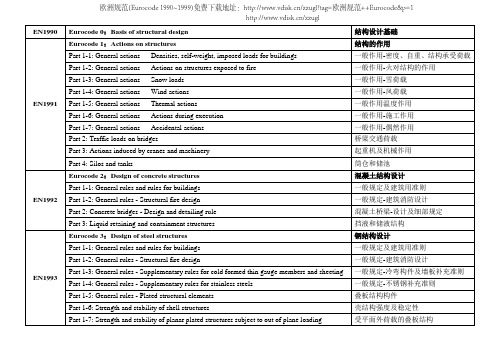
EN1990 Eurocode 0:Basis of structural design 结构设计基础EN1991 Eurocode 1:Actions on structures 结构的作用Part 1-1: General actions — Densities, self-weight, imposed loads for buildings 一般作用-密度、自重、结构承受荷载Part 1-2: General actions — Actions on structures exposed to fire 一般作用-火对结构的作用Part 1-3: General actions — Snow loads 一般作用-雪荷载Part 1-4: General actions — Wind actions 一般作用-风荷载Part 1-5: General actions — Thermal actions 一般作用温度作用Part 1-6: General actions — Actions during execution 一般作用-施工作用Part 1-7: General actions — Accidental actions 一般作用-偶然作用Part 2: Traffic loads on bridges 桥梁交通荷载Part 3: Actions induced by cranes and machinery 起重机及机械作用Part 4: Silos and tanks 筒仓和储池EN1992 Eurocode 2:Design of concrete structures 混凝土结构设计Part 1-1: General rules and rules for buildings 一般规定及建筑用准则Part 1-2: General rules - Structural fire design 一般规定-建筑消防设计Part 2: Concrete bridges - Design and detailing rule 混凝土桥梁-设计及细部规定Part 3: Liquid retaining and containment structures 挡液和储液结构EN1993 Eurocode 3:Design of steel structures 钢结构设计Part 1-1: General rules and rules for buildings 一般规定及建筑用准则Part 1-2: General rules - Structural fire design 一般规定-建筑消防设计Part 1-3: General rules - Supplementary rules for cold formed thin gauge members and sheeting 一般规定-冷弯构件及墙板补充准则Part 1-4: General rules - Supplementary rules for stainless steels 一般规定-不锈钢补充准则Part 1-5: General rules - Plated structural elements 叠板结构构件Part 1-6: Strength and stability of shell structures 壳结构强度及稳定性Part 1-7: Strength and stability of planar plated structures subject to out of plane loading 受平面外荷载的叠板结构欧洲规范(Eurocode 1990~1999)免费下载地址:/zzugl?tag=欧洲规范++Eurocode&p=1/zzuglPart 1-8: Design of joints 节点设计Part 1-9: Fatigue 疲劳强度Part 1-10:Material toughness and through-thickness properties 材料韧性及全厚度特性Part 1-11: Design of structures with tension components 受拉构件结构设计Part 1-12: General - High strength steels 一般规定-高强度钢材Part 2: Steel bridges 钢桥Part 3-1: Towers, masts and chimneys – Towers and masts 塔、桅杆及烟囱- 塔、桅杆Part 3-2: Towers, masts and chimneys – Chimneys 塔、桅杆及烟囱- 烟囱Part 4-1: Siloston 筒仓Part 4-2: Tanks 储池Part 4-3: Pipelines 管道Part 5: Piling 桩Part 6: Crane supporting structures 起重机支承结构EN1994 Eurocode 4:Design of composite steel and concrete structures 钢-混凝土混合结构设计Part 1-1: General rules and rules for buildings 一般规定及建筑用准则Part 1-2: General rules - Structural fire design 一般规定- 结构消防设计Part 2: General rules and rules for bridges 一般规定及桥梁用准则EN1995 Eurocode 5:Design of timber structures 木结构设计Part 1-1: General - Common rules and rules for buildings 一般规定及建筑用准则Part 1-2: General rules - Structural fire design 一般规定- 结构消防设计Part 2: Bridges 木桥EN1996 Eurocode 6:Design of masonry structures 砌体结构设计Part 1-1: General rules for reinforced and unreinforced masonry structures 配筋及无筋砌体结构一般规定Part 1-2: General rules - Structural fire design 一般规定- 结构消防设计Part 1-3: General rules for building — Detailed rules on lateral loading欧洲规范(Eurocode 1990~1999)免费下载地址:/zzugl?tag=欧洲规范++Eurocode&p=1Part 2: Design considerations, selection of materials and execution of masonry 砌体结构设计考虑、选材及施工Part 3: Simplified calculation methods for unreinforced masonry structures 无筋砌体结构的简化计算方法EN1997 Eurocode 7:Geotechnical design 岩土工程设计Part 1: General rules 一般规定Part 2: Ground investigation and testing 地基勘察及试验Part 3: Design assisted by fieldtesting 现场试验辅助设计EN1998 Eurocode 8:Design of structures for earthquake resistance 结构抗震设计Part 1: General rules, seismic actions and rules for buildings 一般规定-建筑的地震作用Part 2: Bridges 桥梁Part 3: Assessment and retrofitting of buildings 建筑的鉴定及加固Part 4: Silos, tanks and pipelines 筒仓、储池及管道Part 5: Foundations, retaining structures and geotechnical aspects 基础、挡土结构及其土工问题Part 6: Towers, masts and chimneys 塔、桅杆及烟囱EN1999 Eurocode 9:Design of aluminium structures 铝结构设计Part 1-1: General rules - General rules and rules for buildings 一般规定及建筑用准则Part 1-2: General rules - Structural fire design 一般规定- 结构消防设计Part 1-3: Structures susceptible to fatigue 易疲劳破坏结构Part 1-4: Cold-formed structural sheeting 冷弯成型结构薄板Part 1-5: Shell structures 壳体结构Part 2: Structures susceptible to fatigue 易疲劳破坏结构欧洲规范(Eurocode 1990~1999)免费下载地址:/zzugl?tag=欧洲规范++Eurocode&p=1欧洲规范(Eurocode 1990~1999)免费下载地址:/zzugl?tag=欧洲规范++Eurocode&p=1/zzugl。
ATC-63 报告第七章:性能评价
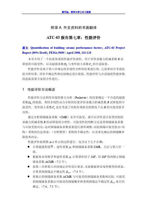
附录A 外文资料的书面翻译ATC-63报告第七章:性能评价原文: Quantification of building seismic performance factors, ATC-63 Project Report (90% Draft), FEMA P695 / April 2008, 115-128本章介绍了一个抗震体系的性能评价流程,用于评价承载力折减系数R 试算值的可接受性,以及超强系数O Ω与变形放大系数d C 的合适取值。
性能评价是基于第六章规定的非线性分析的结果进行的。
它需要综合考虑抗震分析结果、评估不确定性和近似确定设计取值。
性能评价与合适地震性能参数的选取需要专家组合作进行。
1 性能评价方法概述性能评价方法利用非线性静力分析(Pushover )的结果确定一个合适的超强系数O Ω的取值,利用非线性动力分析的结果评估承载力折减系数R 试算值的可接受性。
变形放大系数d C 是在考虑了结构有效阻尼的情况下由R 的可接受值导出的。
通过分析倒塌储备系数(CMR )是否可接受,就可以评价设计原型结构的承载力折减系数R 的试算值的合理性。
可接受性的判断方法是将倒塌储备系数与可接受值对比,这时倒塌储备系数需要进行谱形调整。
而抗倒塌可接受值由(结构)系统的信息质量,(分析模型)系统的不确定性,以及事先确定的倒塌概率限值来决定。
性能评价按照图A-1所示的过程进行,包含以下几个步骤:z 计算超强程度Ω、延性系数c µ和倒塌储备系数CMR ,方法与第六章一致。
z 根据基本周期T 和延性系数c µ计算谱形因子SSF ,用SSF 得到修正倒塌储备系数ACMR (7.2节)。
z 按第三章和第六章的规定评价设计要求、实验数据和非线性模型的质量,计算系统倒塌总不确定性TOT β(7.3节)。
z 将修正的倒塌储备系数ACMR 与可接受的倒塌储备系数相比较。
可接受的倒塌储备系数由可接受的倒塌概率和系统倒塌总不确定性TOT β来共同确定。
关于研究抗震标准的参考文献
关于研究抗震标准的参考文献以下是一些关于研究抗震标准的参考文献:1. 《建筑抗震设计规范》(GB50011-2010):中国国家标准,规范建筑抗震设计的要求和方法。
2. Newmark, N. M. (1949). A method of computation for structural dynamics. Journal of the engineering mechanics division, 85(3),67-94.:介绍了结构动力学计算方法,为抗震设计提供了理论基础。
3. Chopra, A. K. (2005). Dynamics of structures: theory and applications to earthquake engineering. Prentice Hall.:介绍了结构动力学理论和地震工程应用,有助于理解抗震设计的基本原理。
4. FEMA P-750, NEHRP recommended provisions for seismic regulations for new buildings and other structures: 这是美国联邦紧急管理局(FEMA)发布的标准,提供了针对新建筑和其他结构的抗震法规建议。
5. European Committee for Standardization. (2004). EN 1998-1: 2004 Eurocode 8: Design of Structures for Earthquake Resistance-Part 1: General Rules, Seismic Actions and Rules for Buildings. Brussels, Belgium: European Committee for Standardization:欧洲标准化委员会发布的欧洲抗震标准,包括抗震设计的一般规则和建筑的地震力作用要求。
建筑结构抗震课程复习英文版
Seismic Design of Building StructuresChapter 1 Introduction1.The types and causes of earthquakes (地震的类型和成因)Man-made earthquakes, explode, mining operation, major project construction (such as reservoir) Natural earthquakesTectonic earthquake, tectonic activity of lithosphereV olcanic Earthquakes, volcanic eruptions2.Some terminologies about earthquakes, focus, epicenter, focal depth, epicenter distance andisoseismal line (地震的一些相关术语,如震源,震中,震源深度,震中距,等震线)Focus, center or hypocenter, The point where the seismic motion originatesEpifocus or epicenter, The projection of the focus onto the surface of the earthFocal depth, The depth of hypocenter below the epicenterEpicenter distance, The distance from the epicenter to the point of the observed ground motion Isoseismal line一次地震中,在受影响的区域内,烈度相同的区域的外包线3.The classification of seismic waves. (地震波的类型)Body waves include Primary Wave (P wave) and Secondary Wave (S wave)Surface waves include Rayleigh wave (R wave) and Love wave(Love wave)4.The essential factors of ground motion. (地震动的三要素)Magnitude/amplitude(幅值)Frequency/spectrum (频率)Duration (持时)5.The concept of earthquake magnitude and intensity and the difference between them. (震级与烈度的概念以及它们之间的区别)The earthquake magnitude means the energy released in an earthquakeEarthquake intensity is an indication of the severity of ground shaking at a specific site which is based on the observe defects of an earthquake and a qualitative assessment of the damage that causedThere is only one magnitude for an earthquake, but maybe many intensities for different locations.Because intensity scales are subjective and depend upon social and construction conditions of a country, they need revision from time to time. Regional effects must be accounted for.6.Three-level seismic fortification objectives and Two-phase seismic design method. (三水准抗震设防与两阶段设计)The first level: No damage under minor earthquake (小震不坏)The Second level: Repairable damage under moderate earthquake (中震可修)The third level: No collapse under large earthquake (大震不倒)Phase1: By the elastic analysis, the carrying capacity of the structure is checked under the fundamental combination of effects of seismic action of minor earthquake and other loads, and the elastic seismic deformation is checked under the action of minor earthquakes.Phase2: The elastoplastic deformation is checked under the action of rare earthquake.The structural design through the first phase can satisfy the requirements of the first seismic fortification level1. The structural design through the second phase can guarantee the seismic fortification level3.The Seismic Fortification Objective2 is guaranteed by constructional measures(构造措施)and conceptual design(概念设计).7.The meanings of Minor, Moderate and Large earthquake. (小震,中震,大震的含义)Frequently occurred earthquakes with an intensity of less than the fortification intensity of the region Earthquakes equal to the fortification intensity of the regionRare earthquakes with an intensity higher than the fortification intensity of the region.8.Three aspects of seismic design of buildings. (建筑抗震三个层次的内容)Seismic conceptual design, seismic computation, construction measures9.In Chinese Code for Seismic Design of Buildings, what factors are related to height limits ofbuildings? (根据中国抗震设计规范,哪些因素与建筑物高度限值有关?)Site condition, fortification intensity of the region, structural type, using requirements, economy issues10.Why the resisting members should be placed on the perimeter? (为何抗侧力构件应当布置在周边?)Increase the moment arm, thus increasing the lateral stiffness and carrying capacity for horizontal load 11.From the seismic view, what characters should be the desirable aspects of building configuration onthe overall form? (从抗震角度来看,建筑物理想的总体造型有什么特征?)The desirable aspects of building configuration are simplicity, regularity, and symmetry in both plan and elevation.These properties all contribute to a more even distribution of earthquake forces in the structural system.12.Illustrating the attributes of the optimum seismic configuration and giving the reasons. (说明建筑物抗震设计的最优外形特征,并解释其原因)1. Low aspect ratio (minimize tendency to overturn)2. Equal floor heights (equalize column/wall stiffness)3. Symmetrical plan shape (reduce torsion)4. Identical resistance on both axes (balanced resistance in all directions)5. Uniform section and elevations (eliminate stress concentrations)6. Seismic resisting elements at perimeter (maximum torsional resistance)7. Redundancy (toleration of failure of some members)8. Direct load paths (less stress concentrations)13.According to Chinese Code for Seismic Design of Buildings, what are the requirements for seismicstructural system? (根据中国的抗震设计规范,对于结构体系抗震方面的要求有哪些?)1. It shall have a clear analytical model and reasonable path for seismic action transfer.2. It should have several lines of defense against earthquakes. It should avoid loss of either earthquake resistance capacity or gravity load capacity of the whole system due to damage to part of the structure or members.3. It shall possess the necessary strength, adequate deformability, and better energy dissipation ability.4. It should possess a rational distribution of stiffness and strength, avoid weakening of some parts of the structure due to local weakening or abrupt changes; avoid appearance of extremely large concentration of stress and plastic deformation; when weak parts do appear, measures should be taken to enhance their earthquake resistance capacity.5. It should have similar dynamic characteristics in the direction of individual primary axis.Chapter 2 Site and Subsoil1.The seismic effect of structures influenced from the construction site. (场地对结构地震效应的影响)High-rise buildings founded on soft soils were more damaged than the similar buildings founded on rock.The seismic waves propagated in the lithosphere have many contents of frequencies. The period which is related to the maximum value in the vibration amplitude is termed as Predominant Period(卓越周期).If the frequency of the structure is near to the one of seismic wave, the serious damages can happen in the structures. (resonance, 共振)The seismic effect of soil depends mostly on the thickness of overlaying soil(覆盖土层厚度), shear-wave velocity (剪切波速)and impedance ratio (阻抗比) of soil.The thickness of overplaying soil and shear-wave velocity mainly influence the frequency properties of seismic wave2.The categories of sites and how to classify them. (场地的类型及划分原则)Construction sites shall be classified into four categories according to the type of site soil and the overlaying thickness at the site, and should also comply with the table2.3.3.How to check the bearing capacity of natural subsoil. (如何验算地基土的抗震承载力)Except the building listed above, the bearing capacity of natural subsoil and foundation should be checked for earthquake resistance by the following equation: f aE=ξa f a (ξa≥1)4.The cause of soil liquefaction. (砂土液化产生的原因)p25 During strong earthquake shaking, a loose saturated sand deposit (饱和松散的砂土) will have a tendency to compact, which will result in a decrease in volume and increase in the pore water pressure.If the pore water pressure increases to overburden pressure, the effective pressure will be zero. Since the shear strength of soil is directly proportional to the effective stress, the sand will not have any shear strength and is now in a “liquid” state, which is called soil liquefaction.5.The procedure of discrimination for the liquefaction potential. (砂土液化的判别步骤)Preliminary DiscriminationGenerally, the discrimination of the potential of liquefaction of the saturated soil and adoption of methods to prevent liquefaction need not be considered when intensity is Ⅵ, but for Type B buildings which are sensitive to the settlement caused by liquefaction, the subsoil can be treated as intensity Ⅶ.When the intensity is Ⅶto Ⅸ, for type B buildings, discrimination of the potential of liquefaction and adoption of relevant methods may be considered using the specifications of the local fortification intensity.If one of the following conditions is satisfied, saturated sand or silt may be preliminarily discriminated as non-liquefiable soil, or effects of liquefaction need not be considered…(1)If the geological period of the soil is the Pleistocene of the Quaternary period (Q3) or earlier, thesoil may be considered as non-liquefiable when the intensity is Ⅶor Ⅷ.(2)If the clay particle content (particle diameter less than 0.005mm) of slit (粉土) is not less than 10%,13% and 16%, when the intensity is Ⅶ, Ⅷand Ⅸrespectively(3)For buildings resting on natural subsoil, effects of liquefaction need not be considered when thethickness of the non-liquefiable overlaying layer (上覆非液化土层厚度) and the depth of underground water level (地下水位深度)comply with one of the following conditions:Standard penetration tests6.The meanings of liquefaction index. (液化指数的含义)For the subsoil with liquefaction-potential soil layers, its category of liquefaction shall be classified according to the liquefaction indexChapter 3 Response Analysis of Engineering Structures1.The meanings of seismic response spectrum. (地震反应谱的含义)The relationship between maximum absolute acceleration Sa of SDOF system and its period T2.The mode shapes of MDOF systems. (多自由度体系的振型)The structural response can be decomposed to many independent coordinates. The independence of coordinate axis is the orthogonality.3.The procedures of mode-superposition spectrum method. (振型分解反应谱法的基本步骤)4.The application condition and procedure of base shear method. (底部剪力法的适用条件及步骤)(1)The structural height is less than 40m;(2) The deformation of the structure should be shear type with evenly distribution of mass andstiffness in the vertical direction.(3) Approximately SDOF system.5.What kind of structures should be analyzed including vertical seismic action. (哪些结构需要考虑竖向地震作用)Tall buildings (Intensity 9), large-span or long cantilever structures (Intensity 8 and 9)6.The meanings of representative value of gravity load. (重力荷载代表值的含义)p69 When earthquake happens, the variable loads acting on structure often does not reach their characteristic values. In seismic design, the representative value of gravity load is the addition of characteristic value of weight and combination values of relevant variable loads.7.The contents of seismic checking of structures. (结构抗震验算的内容)Strength checking and deformation checking(1)The deformation checking of structures under frequently occurred earthquake is to avoid thedamage of non-structural members.(2)The strength checking of structures under frequently occurred earthquake is to avoid the damage ofstructural members.(3)The deformation checking of structures under rare occurred earthquake is to avoid the collapse ofstructures.The requirement of “Repairable damage under moderate earthquake”is guaranteed by seismic concept design and construction measurements.Chapter 5 Seismic Design of Concrete Structures1.The basis and meanings for seismic grading of RC structures. (混凝土结构抗震等级划分的依据及意义)grading of reinforced concrete structures is a practical scale governed by earthquake design philosophy.respect to seismic intensity, types of structural systems, and the overall height of buildings, reinforced concrete building structures are classified as four seismic grades.2.The distribution of seismic action among lateral force-resisting members. (地震作用如何在各抗侧力构件之间进行分配)Seismic action distributes among columns according to the stiffness of each column.3.The difference between inflexion point method and D-Value method. (反弯点法与D值法的区别)Assumption of inflexion point method:(1)The linear stiffness of beam is infinity(2) The zero moment point of bottom story is on the 2/3 height of the column from the base.4.The ductility design methods of RC frame structures. (钢筋混凝土框架结构的延性设计措施)1. Strong Columns with Weak Beams: Plastic hinges should appear at beam ends as much as possible;2. Strong Shear Capacity with Weak Flexure: Avoid the shear damages of beams and columns andensure the ductility of members and structures;3. Strong Joints and Strong Anchoring: Avoid the damages of joints and anchoring failure ofreinforcements.5.The classification of shear walls. (剪力墙的类型及其特点)Integrated Wall,Integrated Wall with small openingCoupled WallsWall Frame6.The layout of shear walls in frame-shear structures. (框剪结构中剪力墙力墙布置原则)(1)Locations where the large vertical loads are applied;There are large axial forces at these locations. The shear walls in these locations can avoid unfavorable eccentric tension.(2) Ends of Buildings;To provide more torsional stiffness.(3)Stair and Elevator room ;Decreased stiffness due to the large openings in the floor.(4) Reentrant cornersTo reduce stress concentration.Axial compression ratioThe influence of axial compression ratio on the shear bearing capacity:Small axial compression, the shear bearing capacity of core concrete in the joints will increase with the increase of axial compression ratio;Large axial compression (0.6~0.8), the shear bearing capacity of core concrete in the joints will decrease with the increase of axial compression ratio;The influence of axial compression ratio on the ductility:The increase of axial compression will result in the decrease of the ductility.。
2 土木工程专业英语1
of the nature of, or caused by an earthquake or vibration of the earth, whether due tonatural or artificial causes. Concept of seismic resistance of building structure结构抗震的概念1Magnitude and Intersity震级和烈度23•The point on the fault where slip starts is the Focus or Hypocenter (震源), and the point vertically above this on the surface of the Earth is the Epicenter (震中).Basic terminology (专业术语)Epicenter FocalDepth Epicentral distancePoint ofinterest•断层上滑移开始的位置称为震源。
•位于震源垂直上方的地表是震中。
4•The depth of focus from the epicenter , called the Focal Depth (震源深度),is an important parameter in determining the damaging potential of an earthquake.Basic terminology Epicenter FocalDepthEpicentral distancePoint ofinterest•从震源到震中的深度称为震源深度。
•震源深度是一个决定地震破坏潜力的重要参数。
5•Most of the damaging earthquakes have shallow focus with focal depths less than about 70 km. The distance from theepicenter to any point of interest is called epicentral distance (震中距).Basic terminology Epicenter FocalDepthEpicentral distancePoint ofinterest•大部分的破坏性地震都有着较浅的震源,震源深度一般小于70公里。
关于建筑抗震的英语演讲
关于建筑抗震的英语演讲Title: Earthquake - Resistant BuildingsI. IntroductionGood morning/afternoon, everyone. Today, I am going to talk about earthquake - resistant buildings. Earthquakes are one of the most destructive natural disasters, and buildings play a crucial role in protecting human lives and property during an earthquake.II. Key Words and Phrases1. Earthquake - resistant- English explanation: Able to withstand the forces generated during an earthquake without collapsing or suffering excessive damage.- Example: Earthquake - resistant design is essential for buildings in seismically active areas.- Usage: It is often used as an adjective to describe buildings, structures, or construction techniques.2. Seismic activity- English explanation: The frequency, type, and size of earthquakes experienced over a period of time in a particular area.- Example: This region has high seismic activity, so strict building codes are in place.- Usage: It is a noun phrase, used to describe the earthquake - related situation of an area.3. Base isolation- English explanation: A technique in which a building is separated from its foundation by a system of bearings or pads that can absorb and dissipate seismic energy.- Example: Base isolation systems can significantly reduce the damage to buildings during an earthquake.- Usage: It is a noun phrase, mainly used in the context of earthquake - resistant building design.4. Damping- English explanation: The process of reducing or dissipating the energy of vibrations, especially in a mechanical or structural system.- Example: Damping devices are installed in some buildings to absorb earthquake - induced vibrations.- Usage: It can be used as a noun or a verb. For example, “The damping of the structure is very important.” (noun) “We need to damp the vibrations.” (verb)5. Reinforced concrete- English explanation: Concrete that has steel bars or mesh embedded in it to increase its strength, especially in tension.- Example: Most modern high - rise buildings are made of reinforced concrete for better earthquake resistance.- Usage: It is a noun phrase, used to describe a type of building material.6. Shear wall- English explanation: A vertical structural element in a building designed to resist lateral forces, such as those caused by earthquakes or wind.- Example: Shear walls are importantponents in earthquake - resistant building design.- Usage: It is a noun phrase, used in architecture and civil engineering.7. Moment - resisting frame- English explanation: A structural frame that is designed to resist bending moments and lateral forces by thebined action of its members.- Example: Moment - resisting frames are often used in high - rise building construction for earthquake resistance.- Usage: It is a noun phrase, used in the field of structural engineering.8. Flexibility- English explanation: The ability of a structure to deform without breaking under the action of external forces, such as earthquake forces.- Example: A certain degree of flexibility in a building can help it better withstand an earthquake.- Usage: It is a noun, and can be used to describe the property of a building or structure.9. Overstrength- English explanation: The additional strength that a structure has beyond the minimum required by design codes, which can provide a margin of safety during an earthquake.- Example: Engineers sometimes design buildings with overstrength to ensure their safety during strong earthquakes.- Usage: It is a noun, used in structural design.10. Redundancy- English explanation: The presence of extra or alternative load - path elements in a structure, so that if one part fails, other parts can still carry the load, which is important for earthquake - resistant design.- Example: Redundancy in building structures can improve their seismic performance.- Usage: It is a noun, used in engineering design.11. Retrofitting- English explanation: The process of modifying an existing building to make it more earthquake - resistant.- Example: Many old buildings need retrofitting to meet modern earthquake - resistant standards.- Usage: It is a gerund (a verb form used as a noun), used to describe an action related to improving old buildings.12. Seismic code- English explanation: A set of regulations and standards for the design, construction, and retrofit of buildings in seismic areas.- Example: Architects and engineers must follow the seismic code when building in earthquake - prone regions.- Usage: It is a noun phrase, used in the building industry.13. Ground motion- English explanation: The movement of the ground during an earthquake, which can cause buildings to shake and be subjected to forces.- Example: The intensity of ground motion varies depending on the magnitude of the earthquake and the local soil conditions.- Usage: It is a noun phrase, used to describe the earthquake - related movement of the ground.14. Response spectrum- English explanation: A plot that shows the maximum response of a single - degree - of - freedom system to different frequencies of ground motion, used in earthquake engineering for design purposes.- Example: Engineers use response spectra to analyze the seismic performance of buildings.- Usage: It is a noun phrase, used in earthquake engineering analysis.15. Lateral load- English explanation: A force acting on a structure in a direction perpendicular to its vertical axis, such as the force caused by an earthquake or wind.- Example: Buildings must be designed to resist lateral loads during an earthquake.- Usage: It is a noun phrase, used in structural engineering.16. Structural integrity- English explanation: The ability of a structure to maintain its overall shape and function without significant damage or failure, especially during an earthquake.- Example: Ensuring the structural integrity of a building is the top priority in earthquake - resistant design.- Usage: It is a noun phrase, used to describe the quality of a structure.17. Tensile strength- English explanation: The maximum stress that a material can withstand while being stretched or pulled before breaking. In earthquake - resistant building, materials with good tensile strength are preferred.- Example: Steel has high tensile strength, which is why it is often used in reinforced concrete for earthquake - resistant structures.- Usage: It is a noun phrase, used to describe a property of materials.18. Compressive strength- English explanation: The maximum stress that a material can withstand while beingpressed before failure. In building structures, materials need to have appropriatepressive strength.- Example: Concrete has goodpressive strength, but its tensile strength is relatively low, so steel reinforcement is added.- Usage: It is a noun phrase, used to describe a property of materials.19. Interstory drift- English explanation: The relative lateral displacement between adjacent floors of a building during an earthquake. Excessive interstory drift can lead to damage or collapse of the building.- Example: Engineers need to control the interstory drift to ensure the safety of the building during an earthquake.- Usage: It is a noun phrase, used in the analysis of building seismic performance.20. Capacity - design- English explanation: A design philosophy in earthquake engineering in which the strength of non - criticalponents is designed based on the capacity of criticalponents, so that in an earthquake, non - criticalponents will yield first, protecting the critical ones.- Example: Capacity - design principles are widely used in modern earthquake - resistant building design.- Usage: It is a noun phrase, used in earthquake - resistant design concepts.III. ConclusionIn conclusion, earthquake - resistant building design is aplex but essential field. By understanding and applying these concepts, words, and phrases, we can create safer buildings in seismically active areas, protecting the lives and property of people. Thank you for listening.。
欧洲规范NA to BS EN 1998
NA to BS EN 1998-1:2004UK National Annex to Eurocode 8: Design of structures for earthquake resistance –Part 1: General rules, seismic actions and rules for buildingsICS 91.120.25NO COPYING WITHOUT BSI PERMISSION EXCEPT AS PERMITTED BY COPYRIGHT LAWNATIONAL ANNEXNA to BS EN 1998-1:2004Publishing and copyright informationThe BSI copyright notice displayed in this document indicates when thedocument was last issued.© BSI 2008ISBN 978 0 580 55090 4The following BSI references relate to the work on this standard:Committee reference B/525/8Draft for comment 07/30129890DCPublication historyFirst published August 2008Amendments issued since publicationAmd. no.Date Text affected© BSI 2008•i NA to BS EN 1998-1:2004ContentsIntroduction 1NA.1Scope 1NA.2Nationally Determined Parameters 2NA.3Decisions on the status of the informative annexes 11NA.4References to non-contradictory complementaryinformation 11Bibliography 12List of tablesTable NA.1 – UK values for Nationally Determined Parametersdescribed in BS EN 1998-1:2004 2Summary of pagesThis document comprises a front cover, an inside front cover,pages i andii, pages 1 to 12, an inside back cover and a back cover.NA to BS EN 1998-1:2004ii•© BSI 2008This page deliberately left blank© BSI 2008•1NA to BS EN 1998-1:2004National Annex (informative) to BS EN 1998-1:2004, Eurocode 8: Design of structures for earthquake resistance – Part 1: General rules, seismic actions and rules for buildingsIntroduction This National Annex has been prepared by BSI Subcommittee B/525/8, Structures in seismic regions . In the UK it is to be used in conjunction with BS EN 1998-1:2004.NA.1ScopeThis National Annex gives:a)the UK decisions for the Nationally Determined Parametersdescribed in the following subclauses of BS EN 1998-1:2004:b)the UK decisions on the status of BS EN 1998-1:2004 informativeannexes; andc)references to non-contradictory complementary information.2.1(1)P 5.2.2.2(10)7.1.3(4)2.1(1)P 5.2.4(1),(3)7.7.2(4)3.1.1(4) 5.4.3.5.2(1)8.3(1)3.1.2(1) 5.8.2(3)9.2.1(1)3.2.1(1),(2),(3) 5.8.2(4)9.2.2(1)3.2.1(4) 5.8.2(5)9.2.3(1)3.2.1(5) 5.11.1.3.2(3)9.2.4(1)3.2.2.1(4), 3.2.2.2(1)P 5.11.1.49.3(2)3.2.2.3(1)P 5.11.1.5(2)9.3(2)3.2.2.5(4)P 5.11.3.4(7)e)9.3(3)4.2.3.2(8) 6.1.2(1)9.3(4), Table 9.14.2.4(2)P 6.1.3(1)9.3(4), Table 9.14.2.5(5)P 6.2(3)9.5.1(5)4.3.3.1(4) 6.2(7)9.6(3)4.3.3.1(8) 6.5.5(7)9.7.2(1)4.4.2.5(2) 6.7.4(2)9.7.2(2)b)4.4.3.2(2)7.1.2(1)9.7.2(2)c)5.2.1(5)7.1.3(1),(3)9.7.2(5)10.3(2)P2•© BSI 2008NA to BS EN 1998-1:2004NA.2Nationally Determined ParametersUK decisions for the Nationally Determined Parameters described inBS EN 1998-1:2004 are given in Table NA.1.Table NA.1UK values for Nationally Determined Parameters described in BS EN 1998-1:2004Subclause Nationally Determined Parameter Eurocode recommendation UK decision2.1(1)P Reference return period T NCR of seismic action for the no-collapse requirement (or, equivalently , reference probability of exceedance in 50 years, P NCR ).T NCR =475 years P NCR =10%In the absence of a project-specific assessment,adopt a return periodT NCR of 2 500 years. Furtherguidance is given in PD 6698.2.1(1)P Reference return period T DLR of seismic action for the damage limitation requirement (or, equivalently , reference probability of exceedance in 10 years, P DLR ).T DLR =95 years P DLR =10%In the absence of a project-specific assessment,adopt the recommended values.Further guidance is given in PD 6698.3.1.1(4)Conditions under which ground investigations additional to those necessary for design for non-seismic actions may be omitted and default ground classification may be used.[None]The need for additional ground investigationsshould be established on a site-specific basis. Further guidance is given in PD 6698.3.1.2(1)Ground classification scheme accounting for deep geology , including values of parameters S , T B , T Cand T D defining horizontal and vertical elastic response spectra in accordance with BS EN 1998-1:2004, 3.2.2.2 and 3.2.2.3.[None]There is no requirement to account for deep geology .Further guidance is given in PD 6698.3.2.1(1),(2),(3)Seismic zone maps and reference ground accelerations therein.[None]In the absence of a project-specific assessment, adopt the reference ground accelerations for a return period T NCR of 2 500 years given by theseismic contour map in PD 6698.3.2.1(4)Governing parameter (identification and value) for threshold of low seismicity .a g u 0,78m/s 2 or a g S u 0,98m/s 2a g u 2m/s 2 (for T NCR =2 500 years)3.2.1(5)Governing parameter (identification and value) for threshold of very low seismicity .a g u 0,39m/s 2 or a g S u 0,49m/s 2a g u 1.8 m/s 2 (for T NCR =2 500 years)© BSI 2008•3NA to BS EN 1998-1:2004Table NA.1UK values for Nationally Determined Parameters described in BS EN 1998-1:2004 (continued )SubclauseNationally Determined Parameter Eurocode recommendation UK decision3.2.2.1(4), 3.2.2.2(1)P Parameters S, T B , T C , T D defining shape of horizontal elastic response spectra.In the absence of deep geology effects, and for Type 1 spectra (where earthquakes that contribute most to the seismic hazard defined for the site for the purpose of probabilistic hazard assessment have a surface-wave magnitude, M s , greater than 5,5):In the absence of site-specific information, therecommended values for Type 2 earthquakes maybe used, but see also PD 6698.Ground type S T B (s)T C (s)T D (s)A 1,00,150,42,0B 1,20,150,52,0C 1,150,200,62,0D 1,350,200,82,0E 1,40,150,52,0In the absence of deep geology effects, and for Type 2 spectra (where earthquakes that contribute most to the seismic hazard defined for the site for the purpose of probabilistic hazard assessment have a surface-wave magnitude, M s , less than 5,5):Ground type S T B (s)T C (s)T D (s)A 1,00,050,251,2B 1,350,050,251,2C 1,50,100,251,2D 1,80,100,301,2E 1,60,050,251,23.2.2.3(1)P Parameters a vg , T B , T C , T D defining shape of vertical elastic response spectra.Spectrum a vg /a g T B (s)T C (s)T D (s)In the absence of site-specific information, therecommended values for Type 2 earthquakes maybe used, but see also PD 6698.Type 10,900,050,151,0Type 20,450,050,151,03.2.2.5(4)P Lower bound factor β on design spectral values. 0,2Use the recommended value.4•© BSI 2008NA to BS EN 1998-1:2004Table NA.1UK values for Nationally Determined Parameters described in BS EN 1998-1:2004 (continued )Subclause Nationally Determined Parameter Eurocode recommendation UK decision4.2.3.2(8)Reference to definitions of centre of stiffness and of torsional radius in multi-storey buildings meeting or not conditions (a) and (b) of BS EN 1998-1:2004, 4.2.3.2(8).[None]Any appropriate method may be used.Further guidance is given in PD 6698.4.2.4(2)P Ratio ϕ of coefficient ψEi on variable mass used in seismic analysis to combination coefficient ψ2i for quasi permanent values of variable actions.Type of variable action Storey ÎUse the recommended values. Storeys occupied by different tenants may be considered asindependently occupied.Categories A–C*Roof 1,0Storeys with correlated occupancies0,8Independently occupied storeys 0,5Categories D–F*and Archives 1,0* Categories as defined in BS EN 1991-1-1:2002.4.2.5(5)P Importance factor γI for buildings.Class I:γI =0,8Class III:γI =1,2Class IV:γI =1,4Where a value for the reference returnperiod T NCR of 2 500 years has been adoptedfor CC3 structures, γI =1 should be assumed.Where T NCR has been assessed on aproject-specific basis, γI should also be chosenon a project-specific basis. Further guidance is given in PD 6698.4.3.3.1(4)Decision on whether nonlinear methods of analysis may be applied for the design of non-base-isolated buildings. Reference to information on member deformation capacities and the associated partial factors for the Ultimate Limit State for design or evaluation on the basis of nonlinear analysis methods.[None]No supplementary advice.© BSI 2008•5NA to BS EN 1998-1:2004Table NA.1UK values for Nationally Determined Parameters described in BS EN 1998-1:2004 (continued )Subclause Nationally Determined Parameter Eurocode recommendation UK decision4.3.3.1(8)Threshold value of importance factor, γI , relating to the permitted use of analysis with two planar models.[None]3D (spatial) analysis models are recommended forall consequence class CC3 buildings.4.4.2.5(2)Overstrength factor γRd for diaphragms.For brittle failure modes, such as shear, γRd =1,3.For ductile failure modes, γRd=1,e the recommended values.4.4.3.2(2)Reduction factor ν for displacements at damage limitation limit state.Class I & II:É =0,4Class III & IV:É =0,5In consequence class CC3 buildings, storey drifts should be checked against the specified limits using the recommended values of reduction factorν.5.2.1(5)Geographical limitations on use of ductility classes for concrete buildings.[None]There are no geographical limitations.5.2.2.2(10)q o -value for concrete buildings subjected to special Quality System Plan.Adjustment to q o -value is a factor in the range 1 to 1,2, with no recommended value within this range.An adjustment factor of up to 1,2 onq o ispermitted if a formal quality plan is applied to the design, procurement and construction. The design quality plan should include a peer review of the seismic design and the construction quality plan should include special inspection measures for the critical (dissipative) regions.5.2.4(1), (3)Material partial factors for concrete buildings in the seismic design e the γc and γs values for the persistent and transient design e the recommended values.5.4.3.5.2(1)Minimum web reinforcement of large lightly reinforced concrete walls.The minimum value for walls given in BS EN 1992-1-1:2002 and its National e the recommended values.5.8.2(3)Minimum cross-sectional width b w, min and depth h w, min of concrete foundation beams. Buildings up to 3 storeys:bw, min =0,25mh w, min =0,4mBuildings with 4 or more storeys:b w, min =0,25mh w, min =0,5mUse the recommended values.6•© BSI 2008NA to BS EN 1998-1:2004Table NA.1UK values for Nationally Determined Parameters described in BS EN 1998-1:2004 (continued )SubclauseNationally Determined Parameter Eurocode recommendation UK decision5.8.2(4)Minimum thickness t min and reinforcement ratioρs, min of concrete foundation slabs.t min = 0,2mρs, min = 0,2%Use the recommended values.5.8.2(5)Minimum reinforcement ratio ρb, min of concrete foundation beams.ρb, min = 0,4%ρb, min = 0,2% in top face and 0,2% in bottom face.5.11.1.3.2(3)Ductility class of precast wall panel systems.DCM Use the recommended value.5.11.1.4Factor k p on q -factors of precast systems.k p = 1,0 for structures with connections conforming to BS EN 1998-1:2004, 5.11.2.1.1,5.11.2.1.2, or 5.11.2.1.3k p = 0,5 for structures with other types ofconnection Use the recommended values.5.11.1.5(2)Ratio A p of transient seismic action assumed during erection of precast structures to design seismic action defined in BS EN 1998-1:2004, Section 3.A p = 0,3 unless otherwise specified by special studies In the absence of a site-specific assessment, use therecommended value.5.11.3.4(7)e)Minimum longitudinal steel ρc, min in grouted connections.ρc, min =1%Use the recommended value.6.1.2(1)Upper limit of q for low-dissipative structural behaviour concept.1,52Further guidance is given in PD 6698.Limitations on structural behaviour concept.[None]No limitations on structural behaviour concept. Further guidance is given in PD 6698.Geographical limitations on use of ductility classes for steel buildings.[None]No geographical limitations. Further guidance is given in PD 6698.6.1.3(1)Material partial factors for steel buildings in the seismic design e the γs values for the persistent and transient design e the recommended values.6.2(3)Overstrength factor for capacity design of steel buildings.γov = 1,25Use the recommended value.© BSI 2008•7NA to BS EN 1998-1:2004Table NA.1UK values for Nationally Determined Parameters described in BS EN 1998-1:2004 (continued )SubclauseNationally Determined Parameter Eurocode recommendation UK decision6.2(7)Information as to how BS EN 1993-1-10:2005 – selection of steel for fracture toughness and through thickness properties – may be used in the seismic design situation.[None]The fracture toughness and through thicknessproperties of the steel should be selected on a project-specific basis. Further guidance is given in PD 6698.6.5.5(7)Reference to complementary rules on acceptable connection design.[None]Complementary rules for connection design may be developed on a project-specific basis. Further guidance is given in PD 6698.6.7.4(2)Residual post-buckling resistance of compression diagonals in steel frames with V -bracings.γpb = 0,3γpb = γpb * N b,Rd (λbar)/ Npl,Rd(γpb * times design buckling resistance over plasticresistance)γpb * = 0,7 for q u 2= 0,3 for qW 5For 2u q u 5, γpb *= 0,3 may be assumed or refer to PD 6698.Further guidance is given in PD 6698.7.1.2(1)Upper limit of q for low-dissipative structural behaviour concept.1,52Limitations on structural behaviour concept.[None]No limitations on structural behaviour concept.Geographical limitations on use of ductility classes for composite steel-concrete buildings.[None]No geographical limitations.7.1.3(1),(3)Material partial factors for composite steel-concrete buildings in the seismic design e the γs values for the persistent and transient design e the recommended values.7.1.3(4)Overstrength factor for capacity design of composite steel-concrete buildings.γov = 1,25Use the recommended value.8•© BSI 2008NA to BS EN 1998-1:2004Table NA.1UK values for Nationally Determined Parameters described in BS EN 1998-1:2004 (continued )SubclauseNationally Determined Parameter Eurocode recommendation UK decision7.7.2(4)Stiffness reduction factor for concrete part of a composite steel-concrete column section.r =0,5In the absence of special studies, use the recommended value.8.3(1)Geographical limits on ductility class for timber buildings.[None]No geographical limits.9.2.1(1)Type of masonry units with sufficient robustness.[None]Any type of masonry unit listed in BS EN 1996-1-1:2005, Table 3.1, is acceptable.9.2.2(1)Minimum strength of masonry units.f b,min = 5N/mm 2 (normal to bedface)f bh,min = 2N/mm 2 (parallel to bedface)Use the minimum values given inBS EN 1996-1-1:2005.9.2.3(1)Minimum strength of mortar in masonry buildings.f m,min = 5N/mm 2 (unreinforced or confined masonry)f m,min = 10N/mm 2 (reinforced masonry)Use the minimum values given inBS EN 1996-1-1:2005.9.2.4(1)Alternative classes for perpend joints in masonry . [None]Perpend joints fully grouted with mortar orungrouted joints with mechanical interlocking between masonry units may be used. Ungrouted joints without mechanical interlock may only be used subject to appropriate validation.9.3(2)Conditions for use of unreinforced masonry satisfying provisions of BS EN 1996-1:2005 alone.[None]There are no restrictions on the use of unreinforced masonry that follows the provisions of BS EN 1996-1:2005 alone.9.3(2)Minimum effective thickness t ef,min of unreinforced masonry walls satisfying provisions of BS EN 1996-1:2005 alone.t ef,min = 240 mm t ef,min = 170 mm in cases of low seismicityt ef,min = 170 mm9.3(3)Maximum value of ground acceleration a g,urm for the use of unreinforced masonry satisfying provisions of BS EN1998-1.a g,urm = 0,2 g a g,urm = 0,25 g9.3(4), Table 9.1q -factor values in masonry buildings.Unreinforced masonry in accordance with BS EN 1998-1: q = 1,5Confined masonry: q = 2,0Reinforced masonry: q = 2,5Unreinforced masonry inaccordance with BS EN 1998-1:q = 2,0Confined masonry: q = 2,5Reinforced masonry: q = 3,0© BSI 2008•9NA to BS EN 1998-1:2004Table NA.1UK values for Nationally Determined Parameters described in BS EN 1998-1:2004 (continued )SubclauseNationally Determined Parameter Eurocode recommendation UK decision9.3(4), Table 9.1q -factors for buildings with masonry systems which provide enhanced ductility .[None]Enhanced values need to be justified on a case-by-case basis.9.5.1(5)Geometric requirements for masonry shear walls.Masonry type t ef,min (mm)(h ef /t ef )max (l /h )min Use the recommended values.Unreinforced, with natural stone units 35090,5Unreinforced, with any other type of units240120,4Unreinforced, with any other type of units, in cases of low seismicity170150,35Confined masonry 240150,3Reinforced masonry 24015No restrictionSymbols used have the following meaning:t ef thickness of the wall (seeBS EN 1996-1-1:2005);h efeffective height of the wall (see BS EN 1996 1-1:2005);h greater clear height of the openings adjacent to the wall;l length of the wall.9.6(3)Material partial factors in masonry buildings in the seismic design situation.γm = 2/3 of value specified in National Annex to BS EN 1996-1-1:2005, but not less than 1,5γs = 1,0Use the recommended values.10•© BSI 2008NA to BS EN 1998-1:2004Table NA.1UK values for Nationally Determined Parameters described in BS EN 1998-1:2004 (continued )SubclauseNationally Determined Parameter Eurocode recommendation UK decision9.7.2(1)Maximum number of storeys and minimum area of shear walls of “simple masonry building”.Acceleration at site a g .S u0,07k ⋅g u 0,10k ⋅g u 0,15k ⋅g u 0,20k ⋅g Use the recommended values, unless justified on a project-specific basis.Further guidance is given in PD 6698.Type of construction Number of storeys (n )**Minimum sum ofcross-sections areas ofhorizontal shear walls in each direction, as percentage of the total floor area per storey (p A,min )Unreinforced masonry 12342,0%2,0%3,0%5,0% 2,0%2,5%5,0%n/a*3,5%5,0%n/a n/a n/an/an/a n/aConfined masonry 23452,0%2,0%4,0%6,0%2,5%3,0%5,0%n/a 3,0%4,0%n/a n/a 3,5%n/an/a n/aReinforced masonry 23452,0%2,0%3,0%4,0%2,0%2,0%4,0%5,0%2,0%3,0%5,0%n/a 3,5%5,0%n/a n/a* n/a means “not acceptable”.** Roof space above full storeys is not included in the number of storeys.9.7.2(2)b)Minimum aspect ratio in plan λmin of “simple masonry buildings”.λmin = 0,25Use the recommended value.9.7.2(2)c)Maximum floor area of recesses in plan for “simple masonry buildings”, expressed as a percentage p maxof the total floor plan area above the level considered.p max = 15%Use the recommended value.9.7.2(5)Maximum difference in mass Δm, max and wall area ΔA, max between adjacent storeys of “simple masonry buildings”.Δm, max= 20%ΔA, max= 20%Use the recommended values.10.3(2)P Magnification factor γx on seismic displacements for isolation devices.γx = 1,2 for buildings γx = 1,5 for buildingsNA to BS EN 1998-1:2004 NA.3Decisions on the status of theinformative annexesNA.3.1Elastic displacement response spectrum[BS EN 1998-1:2004, Annex A]BS EN 1998-1:2004 informative Annex A should not be used in the UK.Further guidance is given in PD 6698.NA.3.2Determination of the target displacement for nonlinear static (pushover) analysis[BS EN 1998-1:2004, Annex B]BS EN 1998-1:2004 informative Annex B may be used in the UK as aninformative annex. Further guidance is given in PD 6698.NA.4References to non-contradictorycomplementary informationThe following is a list of references that contain non-contradictorycomplementary information for use with BS EN 1998-1:2004.•PD 6698:2008, Background paper to the UK National Annexes to BS EN 1998-1, BS EN 1998-2, BS EN 1998-4, BS EN 1998-5and BS EN 1998-6;•Manual for the seismic design of steel and concrete buildingsto Eurocode 8. Institution of Structural Engineers, London. Indraft; publication expected 2008.© BSI 2008•11NA to BS EN 1998-1:200412•© BSI 2008BibliographyStandards publicationsBS EN 1993-1-10:2005, Eurocode 3 – Design of steel structures –Part 1-10: Material toughness and through-thickness properties BS EN 1996-1-1:2005, Eurocode 6 – Design of masonry structures –Part 1-1: General rules for reinforced and unreinforced masonry structuresBS EN 1998-1:2004, Eurocode 8 – Design of structures for earthquake resistance – Part 1: General rules, seismic actions and rules for buildingsPD 6698:2008, Background paper to the UK National Annexesto BS EN 1998-1, BS EN 1998-2, BS EN 1998-4, BS EN 1998-5 andBS EN 1998-6Other publications[1] Institution of Structural Engineers: Manual for the seismic design of steel and concrete buildings to Eurocode 8, London: publication expected 2008.NA to BS EN 1998-1:2004 This page deliberately left blankBSI – British Standards Institution BSI is the independent national body responsible for preparing British Standards. It presents the UK view on standards in Europe and at the international level. It is incorporated by Royal Charter.RevisionsBritish Standards are updated by amendment or revision. Users of British Standards should make sure that they possess the latest amendments or editions.It is the constant aim of BSI to improve the quality of our products and services. We would be grateful if anyone finding an inaccuracy or ambiguity while using this British Standard would inform the Secretary of the technical committee responsible, the identity of which can be found on the inside front cover.Tel:+44(0)2089969000 Fax:+44(0)2089967400BSI offers members an individual updating service called PLUS which ensures that subscribers automatically receive the latest editions of standards.Buying standardsOrders for all BSI, international and foreign standards publications should be addressed to Customer Services. Tel:+44(0)2089969001Fax:+44(0)2089967001 Email:orders@You may also buy directly using a debit/credit card from the BSI Shop on the Website /shop.In response to orders for international standards, it is BSI policy to supply the BSI implementation of those that have been published as British Standards, unless otherwise requested.Information on standardsBSI provides a wide range of information on national, European and international standards through its Library and its Technical Help to Exporters Service. Various BSI electronic information services are also available which give details on all its products and services. Contact the Information Centre. Tel:+44(0)2089967111 Fax:+44(0)2089967048 Email:info@Subscribing members of BSI are kept up to date with standards developments and receive substantial discounts on the purchase price of standards. For details of these and other benefits contact Membership Administration. Tel:+44(0)2089967002 Fax:+44(0)2089967001 Email:membership@Information regarding online access to British Standards via British Standards Online can be found at /BSOL.Further information about BSI is available on the BSI website at.CopyrightCopyright subsists in all BSI publications. BSI also holds the copyright, in the UK, of the publications of the international standardization bodies. Except as permitted under the Copyright, Designs and Patents Act 1988 no extract may be reproduced, stored in a retrieval system or transmitted in any form or by any means – electronic, photocopying, recording or otherwise – without prior written permission from BSI.This does not preclude the free use, in the course of implementing the standard, of necessary details such as symbols, and size, type or grade designations. If these details are to be used for any other purpose than implementation then the prior written permission of BSI must be obtained.Details and advice can be obtained from the Copyright & Licensing Manager. Tel:+44(0)2089967070 Email:copyright@ NA to BS EN 1998-1:2004BSI Group Headquarters 389 Chiswick High Road,London W4 4AL, UK Tel +44 (0)20 8996 9001Fax +44 (0)20 8996 7001/standards。
摩擦摆支座FPB
Earthquake Protection Systems, Inc.451 Azuar Drive, Bldg. 759, Mare Island, Vallejo, California 94592E P S Tel: (707) 644-5993 Fax: (707) 644-5995Sept. 2003TECHNICAL CHARACTERISTICSOFFRICTION PENDULUM TM BEARINGSGENERAL DESCRIPTIONFriction Pendulum TM bearings are seismic isolators that are installed between a structure and its foundation to protect it from damage due to earthquake shaking. The bearings reduce lateral loads and shaking movements transmitted to the structure. They can protect structures and their contents during strong, magnitude 8 earthquakes, and can accommodate near fault pulses and deep soil sites.Friction Pendulum TM bearings use the characteristics of a pendulum to lengthen the natural period of the isolated structure so as to avoid the strongest earthquake forces. The period of the bearingbearings can support vertical loads up to 30 million pounds, and tension load capacities of up to 2 million pounds. The Friction Pendulum TM bearing’s versatile properties permit the seismic isolation design to be optimized for best seismic performance and lowest construction cost.The reliability of the dynamic and sliding properties of Friction Pendulum TM bearings has been verified through hundreds of rigorous tests performed at internationally renowned earthquake engineering research centers [Refs. 1, 4, 6, 7, 9, 15, 16, 17, 18, 27, 28, 29, 30]. Test results demonstrate a consistent and reliable bi-linear response with no degradation under repeated cyclic loadings. The specified effective stiffness and damping values are accurately delivered for either unscragged or scragged bearings, new or aged bearings, and for temperatures ranging from 30 °F to 100 °F. Tests of full-size bearings show that they retain their full strength and stability throughout their displacement range, with high strength factors of safety.The semi-spherical design of the articulated slider achieves relatively uniform pressures under the articulated slider. The relatively uniform pressure distribution reduces slip-stick motion and prevents high local bearing pressure from occurring.The lateral restoring stiffness of the Friction Pendulum TM bearing is,k = W/Rwhere W is the supported weight and R is the length of the radius of curvature of the concave surface. This is the stiffness of a simple pendulum. The fact that the period of the Friction Pendulum TM bearing is independent of the mass of the supported structure is an important property which has advantages in controlling the response of a structure. The desired period can be selected simply by choosing the radius of curvature of the concave surface. The period does not change for light or heavy structures, or if the weight of the structure changes or is different than assumed. The damping is controlled by the hysteretic dynamic friction which also automatically adjusts for uncertainties or changes in structure mass. This ability of the bearing to automatically adjust for uncertain or added structure mass improves safety. Larger than expected bearing displacements, that would otherwise occur with larger than expected structure masses, are avoided.TENSION CAPACITYEPS offers a cylindrical version of our Friction Pendulum TM bearing, that can carry tension loads. This bearing typically has two orthogonal cylindrical rails interconnected by a housing-slider assembly. The housing slider assembly contains two cylindrical sliders, and the housing unit which structurally interconnects the two orthogonal rails. When loaded in compression this cylindrical bearing has the same pendulum based seismic isolation properties, including period stiffness, and friction damping, as the spherical bearing. However the cylindrical tension bearing also maintains the pendulum based seismic isolation properties while carrying tension loads. The cylindrical tension bearing allows free multi-directional shear movements as with the non-tension spherical bearing. Bearing tension capacity provides overall structural connectivity and integrity. The cylindrical bearing is also available with a single rail, permitting sliding movements in one direction, while restraining against movement in the perpendi direction.Tension Bearing Tension Bearing in Test MachinePERFORMANCE AND QUALITY ASSURANCE TESTINGThe performance and properties of Friction Pendulum TM isolators have been supported by extensive testing at internationally renowned earthquake engineering research centers, including: the National Center for Earthquake Engineering Research (NCEER), State University of New York at Buffalo (now known as MCEER); and the Earthquake Engineering Research Center (EERC), University of California, Berkeley.The experimental hysteretic loops demonstrate an ideal bi-linear response of the Friction Pendulum TM with no observable degradation under repeated cyclic loadings. The test results of full-size bearings for the U.S. Court of Appeals building show that Friction Pendulum TM isolators retain their full strength and stability throughout their displacement range [9,17]. Friction damping reduces the seismic displacements.The dynamic friction is measured from tests of full-size isolators. The dynamic friction coefficient is calculated by dividing the area of the hysteretic loop by the total displacement travel. The break-away friction is measured during the first movement of the tests. The dynamic friction values from tests of full-size isolators were within 20% of the specified value. Break-away friction is typically equal to, or less than, the dynamic friction value. Under no circumstances did the break-away friction exceed the specified dynamic friction value by more than 20%.The behavior and response of Friction Pendulum TM isolators to a wide range of earthquake loadings and superstructure types have been investigated both experimentally and analytically. Physical properties of the bearings are well established and exhibited a high degree of consistency throughout the entire series of test programs.Test Results for 3 and 10 Cycles, respectively, at 1.2x Design DisplacementEPS Test MachineBearing in Test Machine1992 URM Tests: Isolated structure1992 URM Tests: Non-Isolated structure remains undamaged after 58 earthquakesfails after 3 earthquakes of magnitudes 5, 6 including magnitude 8 earthquake loadings.and 7, respectively.1991 Shake Table Tests of 7 Story Frame1992 Shake Table Tests of Bridge on Flexible PiersThe following table lists chronologically the research test programs on the Friction Pendulum TM seismic isolation bearings performed at University and Government sponsored laboratories. Year LocationDescription Principal Investigator Ref. No. 1986EERC Compression-shear tests of model bearings. Prof. Mahin 16 1986EERC Shake table tests of 2-story steel frame structure. Test Structures modeled full-size buildings with periods ranging from 0.3 to 3.0 sec. and torsional eccentricities of 0% to 45% Prof. Mahin 16 1989EERC Compression-Shear testing of model low friction bearings at velocities up to 20 inches per second. Prof. Mahin 15 1989NCEER Shake table tests of a 6-story steel moment frame (quarter scale model) using bearings below a rigid base. Prof. Constantinou 7,8 1989NCEER Compression-shear tests of model bearings. Prof. Constantinou 7 1990EERC Compression-Shear tests of full-size 2.0 sec. bearings used in the seismic retrofit of a 4-story apartment building. Dr. Zayas 13 1990NCEER Shake table tests of a rigid slab bridge on bearings. Prof. Constantinou 1991NCEER Shake table tests on 7-story steel moment and braced frame buildings (quarter scale) with bearings below individual columns. Prof. Constantinou 1,17 1992 EERC Shake table tests of unreinforced brick/granite masonry panels using full-size 2.5 sec. period bearings. Prof. Mahin 9,171992 NCEER Shake table tests of a highway bridge on flexible piers with the bearings isolating the bridge deck from the piers. Prof. Constantinou 61993 EERC Compression-Shear testing of full-size 2.75 sec. period bearings. Vertical loading 44 to 1275 kips; sliding velocities from 0.1 to 20inches per sec.; temperatures from –20°F to 90°F; simulated agingto 100 years.Dr. Zayas3,17 1994 NCEER Shake table tests of computer equipment supported on bearings. Prof.Constantinou27 1995 NCEER Tests of temperature, longevity and reliability using model bearings. Prof.Constantinou29 1997 ETEC HITEC Compression-Shear tests and 10,000 cycle wear tests of full-size bearings for Caltrans and the Federal Highway Administration (FHWA).ArmandOnesto30 1999 EERC Caltrans shake table tests with bi-directional interaction for bridge applications.Prof. Mahin1999 NCREE Taiwan Shake table tests of model bearings for use in power transmission towers. Prof.Shinozuka2000-2001 UCSD Caltrans High Speed Compression-Shear tests of large (13 feet diameter) bearings for retrofit of the Benicia-Martinez Bridge.Prof. Seible 2001 WA State Univ.Shake table tests of a three story structural model with FP bearing and dampers (NSR Grant project).Prof. Symans31 2001 UCSD Caltrans, High Speed Compression-Shear tests of large Cylindrical Uni-directional FP bearing for retrofit of West Span of OaklandBay Bridge.Prof. Seible32 2001 UCSD Government of Turkey, Bolu Viaduct Project, High Speed Compression-Shear Prototype tests on large FP bearings.Prof. Seible33 2001 UCSD Tennessee DOT, I-40 Project High Speed Compression-Shear tests of large FP bearings with vertical loads of up to 10,000 KipsProf. Seible34 2002 MCEER Shake table tests of cylindrical tension bearings Prof.Constantinou35The performance and design of the Friction Pendulum TM isolation system for the U.S. Court of Appeals was verified with shake table tests of unreinforced masonry structural models at the Earthquake Engineering Research Center, in August 1992. The isolated models were subjected to over 200 earthquake tests, including large, magnitude 8 earthquakes, without sustaining any damage to the masonry panels. The isolation bearings were then locked in place, and the non-isolated structural model was tested. After 3 small magnitude earthquakes, all of the masonry panels in the non-isolated structure were severely damaged, and testing was stopped.Shake table tests carried out at the National Center for Earthquake Engineering Research in 1991 investigated the response of a 7 story steel framed structure having various lateral load resisting systems. Friction Pendulum TM seismic isolators reduced the structure base shears, story shears, and story drifts in this test structure by factors of 4 to 6. These tests showed that the Friction Pendulum TM isolators were effective in reducing the earthquake loads on multi-story structures having a large overturning aspect ratio and with different structural configurations.The dynamic analysis models used to predict the behavior of the isolated structures have been verified with the results of shake table tests performed at EERC and NCEER. Comparisons of analysis models with test results show that the analysis results reliably and accurately predict the response of Friction Pendulum TM isolated structures.Comparison of Experimental Results and Analytical PredictionTORSION PROPERTIESTheir pendulum properties make Friction Pendulum TM bearings particularly effective at minimizing adverse torsion motions which result from accidental mass eccentricities. The bearing's dynamic stiffness is directly proportional to the supported weight, so that the center of lateral stiffness of the bearings always coincides with the center of mass. Since the friction force is also proportional to the supported weight, the center of the friction forces of the bearing group also coincides with the center of mass of the structure. Hence, the stiffness and friction forces automatically adjust for accidental mass eccentricities. Shake table tests have shown that these torsion properties significantly reduce torsion motions and stresses in the structure, improving structure safety, and reducing bearing displacements at the isolator level [ 7, 15, 16, 17]. Smaller isolator displacements reduce seismic gap requirements and expenses.BEARING COMPRESSION STRENGTHFriction Pendulum TM bearings offer strength and stability that exceed those of any other seismic isolation bearing. An isolator from the U.S. Court of Appeals project in San Francisco, was compression load tested to nine times its design vertical load at the design lateral displacement and at the centered position. The bearing was then cyclically tested under compression and shear, and the results show the bearing retained its operational ability for lateral stiffness, damping, and vertical load capacity.Compression Load Test at Lateral Displacement of 11 inchesIndividual bearings can support service level loads of 30 million pounds. Moreover, the bearings retain high strength factors of safety above the service load capacities. Vertical earthquake motions and seismic overturning moments make the bearing's vertical load factors of safety a critical life safety consideration. Bearings which resist seismic overturning moments experience the maximum vertical loads when they are at the maximum lateral displacement. While laterally displaced, the bearings must also sustain additional vertical loads due to vertical earthquake motions. Furthermore, the reduced vertical stiffness of the bearing, occurring at the design lateral displacement, increases the dynamic amplification of vertical motions, further increasing bearing loads. The vertical earthquake motions can increase bearing vertical loads by factors of 2 or more and should be accounted for in the design. During the Northridge Earthquake, dynamic amplifications exceeding 2 were observed for the vertical seismic motions within buildings supported with elastomeric bearings.Vertical bearing loads due to vertical earthquake motions are usually not explicitly accounted for in the UBC and ASHTO seismic isolation guidelines. To adequately resist vertical earthquake motions and other load uncertainties, EPS recommends the isolation bearings should provide strength factors of safety for compression loads of at least 2.0 at the maximum lateral displacement. UBC and ASHTO seismic isolation guidelines and typical seismic isolation designs with elastomeric bearings have required a vertical load factor of safety of only 1.0 at the maximum lateral displacement. Under combined vertical and lateral earthquake motions, a low strength factor of safety can result in overturning and collapse of the structure during the design seismic event. The most important life safety consideration in the design of seismic isolation bearings is vertical load stability in the laterally displaced position; at this position, isolation bearings perform their intended function and support their maximum loads. COMPRESSION STIFFNESSThe compression stiffness of the Friction Pendulum TM bearings is typically about 7 to 10 times greater than elastomeric isolation bearings. Most importantly, Friction Pendulum TM bearings retain these vertical stiffness values at their design lateral displacement. Typical elastomeric isolation bearings have approximately one half the vertical stiffness at the design displacement as compared to the undeformed position. Thus, the vertical stiffness that resists the overturning moment loads is about 14 to 20 times greater for Friction Pendulum TM bearings than that of elastomeric bearings. This higher vertical stiffness minimizes loss of the structure's shear wall stiffness due to rocking about the base, reduces uplift displacement demand on the bearings, and reduces the need for spreader trusses or walls across the base of the building to spread out the overturning moments. These factors can significantly reduce the isolator installation costs.The higher vertical stiffness of the Friction Pendulum TM also results in a lower vertical period, which is less susceptible to dynamic amplification of the vertical motion. The vertical period of a typical Friction Pendulum TM bearing is approximately 0.03 sec. From the UBC spectra, the dynamic amplification factor is 1.3. The vertical period of the typical elastomeric bearing, at the design lateral displacement, is approximately 0.1 sec. with a dynamic amplification factor of 2.0. The lower dynamic amplification factor for the Friction Pendulum TM bearing reduces vertical bearing loads due to vertical earthquake motions, improving vertical load stability and safety as compared to the specified elastomeric design.UNSCRAGGED AND SCRAGGED PROPERTIESScragging is the repeated lateral loading of an isolation bearing, to achieve a softening of the bearing stiffness. Elastomeric isolation bearings typically recover 70 to 90% of the unscragged properties within 3 months to 2 years after scragging.EPS recommends that structure shear force designs be based on unscragged bearing properties, which are measured from three or fewer cycles of lateral loading to the design lateral displacement applied to a previously untested bearing. Multiple cycles of loading at lesser displacements have a progressive scragging effect and should be avoided when measuring design stiffness and shear values. Basing the structure shear force design on stiffness properties measured after significant prior loading results in unconservative designs. Averaging four or more cycles of loading has a similar unconservative effect.The first cycle of loading on each new virgin bearing tested for the U.S Court and the Revithoussa LNG Tanks, was recorded and reported, as were the subsequent loading cycles. The Friction Pendulum TM bearings demonstrated relatively consistent stiffness and damping properties for either unscragged (virgin) or scragged (previously loaded) bearings. The first cycle of lateral loading on the virgin bearing resulted in friction coefficients approximately 1/2 % higher than those obtained from subsequent cycles. The first cycle virgin properties did not effect the tangent stiffness values. The bearings satisfied the design stiffness and damping requirements for the first and subsequent loading cycles.Since first cycle unscragged properties are stiffer than subsequent cycle properties, they result in higher seismic shear forces in the structure above. For the U.S. Court of Appeals and Revithoussa LNG Tanks, the first cycle properties were used for the structure shear force designs. Since the subsequent cycle properties are less stiff, the subsequent cycle properties were used to check maximum bearing displacement requirements. This approach results in a conservative design for both structure seismic shear forces and bearing displacements. TEMPERATURE EFFECTSLow temperatures increase the stiffness of isolation bearings, and high temperatures reduce the stiffness. This applies to both elastomeric and sliding bearings. EPS recommends that the structure shear force design be based on the cold temperature bearing properties, as applicable to the structure site. Since tests of material samples can produce significantly different results for temperature effects as compared to tests of full size bearings, EPS recommends that bearing temperature effects be based on tests of full size bearings.In order to quantify the effects of temperature on the properties of Friction Pendulum TM isolators, full-size isolators were cooled or heated to the target temperatures at the bearing core, then subjected to combined compression and shear testing. A full-size bearing was cooled to -70 °F, then tested as the temperature gradually rose. Another bearing was heated to 90 °F, then tested as the temperature gradually lowered. The aerospace bearing liner is rated for operation from temperatures ranging from -320°F to +400 °F.The temperature tests showed that friction decreases as the temperature rises, and increases as the temperature decreases. There is no effect of temperature on the bearing dynamic stiffness orperiod. There is a small effect of temperature on the effective stiffness and period due to the friction coefficient change.Effect of Temperature on Dynamic FrictionMATERIAL LONGEVITY AND AGINGThe sliding interface components of the Friction Pendulum TM bearing are constructed of materials with demonstrated longevity and resistance to environmental deterioration and aging [20, 21, 22, 23]. The bearing liner is a high strength, self-lubricating composite material that was developed for use in critical aerospace applications. It meets stringent specifications for use in military applications [21]. The concave sliding surface is a high grade stainless steel with exceptional corrosion and environmental resistance. The durability and long-term material reliability of Friction Pendulum TM bearings result in an expected bearing life exceeding 100 years.The principal properties that affect the performance of seismic isolation bearings are the stiffness, period, and damping. For Friction Pendulum TM bearings, the stiffness and period are controlled by the radius of curvature of the concave surface. The radius of curvature does not change with time. Aging effects on the dynamic stiffness and period of the Friction Pendulum TM bearings are, therefore, not significant.The bearing liner is a high load/low friction composite, which provides non-degrading and low friction sliding, without the use of liquid lubricants. This composite material has been used in the U.S. aerospace industry for over 35 years for high load/high torque bearing applications. The rated static load capacity is 60,000 psi. The rated operating temperature range is -320°F to +400 °F. It provides much higher strength and wear durability than the PTFE materials used in typical bridge or structural bearings.U.S. aerospace applications of this bearing material have very demanding performance and quality control requirements. They include: wing pivot bearings, landing gear bearings,helicopter blade bearings, aircraft engine bearings; and bearings in actuator systems for hydraulics systems; among others. The load requirements in the U.S. military aerospace applications are similar to, or exceed, those of the Friction Pendulum TM bearings. Furthermore, the wear requirements exceed those of the Friction Pendulum TM bearings.U.S. Military Specifications set no age limit or shelf life limit for the use of this bearing material. The bearing material components have been identified as chemically stable and inert, with no noticeable effect of aging. A ten year old sample of the bearing material has been tested and found to show no noticeable deterioration due to age. It's resistance to industrial chemicals is rated as excellent.The other component of the sliding interface is the main stainless steel concave surface. ASTM A240 stainless steel, austenetic grade 300 series with a polished finish, is used for the concave surface.The "Corrosion of Stainless Steels" section of the Metals Handbook Ninth Edition, Vol. 13 Corrosion, ASM International, reports results of observed corrosion of AISI 300 series stainless steels in a marine atmosphere [24]. Stainless steel samples were left exposed for 15 years, 250 meters from the sea. After 15 years, the Type 316 stainless steel exhibited extremely slight rust stains on 15% of the surface. The rust stains were easily cleaned to reveal a bright surface, and would have only a minor effect on the surface roughness and friction coefficient. For a sealed Friction Pendulum TM bearing, installed in a building, similar rust stains would take more than 50 years to develop. Changes in the surface roughness of the concave surface have a modest effect on the dynamic friction value, primarily in the first cycle of loading.To simulate long term aging effects, Friction Pendulum TM bearings were tested with different surface roughnesses, including high mirror polish, low polish, and no polish. The tests were correlated to aging based on the ASM exposure tests, and stainless steel exposure tests by Taylor Devices [20] of stainless steel samples with outdoor and indoor exposure times ranging from 10 to 39 years. The no polish specimen included surface contamination from the steel mill, and was considered a conservative simulation of the worst case 100 year aging effect.The effects of the simulated 100 year aging are shown in the figure on the following page. The figure shows the friction coefficients measured in the first cycle of loading. The 100 year simulated aged bearing demonstrated a 1% increase in the friction coefficient, as compared to the high mirror polish bearing. The friction increase was observed only for the first cycle of loading. Friction results for subsequent cycles were equivalent to the polished bearings.The dynamic friction values of full-size bearings have remained within specification when subjected to repeated loadings during a single test, or over a series of earthquake tests, reaching the design life of the bearings. The wear life of Friction Pendulum TM bearings exceeds thirty design basis earthquake loadings. The friction coefficients of bearings subjected to more than fifty cycles of loading in a single test, and more than fifty sequential earthquake loadings have remained stable and within the design specification.Effect of AgingThe test results for the Friction Pendulum TM composite bearing liner differ from those for soft PTFE materials used in typical structural and bridge bearings. The softer materials creep and impregnate themselves into the mate plates, causing break-away friction values that exceed the dynamic friction values [26]. In contrast, hundreds of tests on Friction Pendulum TM bearings demonstrate the static break away friction coefficient is consistently less than, or equal to, the dynamic friction coefficient [1, 7, 15, 16, 18].Moreover, Friction Pendulum TM bearings were selected for the Revithoussa LNG Tanks over elastomeric bearing types, because they demonstrated the ability to satisfy the stringent performance requirements set for the effects of aging, temperature, and virgin (unscragged) properties. All bearings were required to satisfy the seismic performance requirements under the combined effects of 35 years aging, low temperatures of 10°F, and virgin unscragged properties, as well as the combined effects of new bearing properties, high temperatures of 86°F, and scragged run-in properties. Satisfaction of these performance requirements were required to be demonstrated by performing full-size bearing tests under the specified range of conditions. Elastomeric bearings were tested, but were not able to satisfy the performance requirements. Friction Pendulum TM bearings satisfied all performance requirements.FIRE RESISTANCEThe Friction Pendulum TM bearing offers the innate fire resistance of heavy steel joints. Bearings for bridges typically weigh from 2000 to 10,000 lbs, making a concentrated mass which heats slowly, and maintains stability at temperatures exceeding 1500°F. The aerospace bearing liner can withstand temperatures of 600 °F without damage, and maintains operational ability up to 400°F. All materials are non-combustible, except for the ethyleyne propylene seal which canwithstand temperatures up to 350°F. The seal is replaceable after a fire if needed.The bearings can be fire protected using standard fire protection methods for structural steel members. The exterior may be field sprayed with standard fire proof aggregate. Prior to spraying, the bearing's seismic movement joints should be fitted with expansion joint material to allow bearing movements.The bearing can also be supplied with pre-encased fire board, which can meet the fire rating requirements of an individual project. The fire board is fitted to allow bearing seismic movements, and is removable and replaceable.INSTALLATION DETAILS AND REQUIREMENTSThe Friction Pendulum TM bearings offer many installation benefits compared to elastomeric bearings:•The bearing does not require upper or lower base plates. This saves base plate material costs, handling costs, and installation time.•The FP bearing is vertically stiff, minimizing the vertical deflections of columns that occur during bearing installation in retrofit applications. This avoids damage to architectural finishes in the upper floors, and reducing bearing installation time and cost.•In retrofit applications, the FP bearing does not require flat jacks. This results in savings in flat jack costs and installation time.•The low profile bearing can be installed in constrained locations, saving foundation and structure disruption costs and time.•The FP bearing connection can be welded, offering flexibility and cost savings in details.connection•The tension and side plates of the FP bearing provide the necessary temporary lateral force resistance needed during construction, avoiding the cost, time and space constraints of installing temporary bracing.•The bearings can be installed with the concave surface facing either up or down. P-Delta moments are avoided for the structural members below the isolator, when the concave surface is facing down. This reduces the seismic forces transmitted to the foundation.P-Delta moments are avoided for the structural members above the isolator when the concave surface is facing up. This reduces the seismic forces transmitted to the upper structure.The installation benefits of the Friction Pendulum TM bearings have saved millions of dollars in project construction costs and time.。