超精磨削
普通平面磨床加工超精度、低粗糙度零件

普通平面磨床加工超精度、低粗糙度零件在大型工程机械制造厂磨削表面粗糙度Ra0.02--0.04μm、精度h4--h5的轴颈时,都是在昂贵的高精度平面磨床上进行。
但一般工程机械修造厂却没有高精度平面磨床,要磨削出这样的低的表面粗糙度,如此高的轴颈精度是非常困难的。
我们在现有设备M131W普通外圆平面磨床上进行大量试验,并对其进行必要的检测、刮研和调整,通过修整和精细的平衡砂轮,在磨粒上合适整出更多的等高微刃,就完全可以实现超高精度、低粗糙度的磨销,能有效地磨削出精度h4--h6,粗糙度Ra0.02--0.04μm的零件。
该法简单,方便易行,效果颇佳。
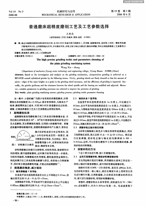
1、超精磨削机理超精磨削是靠砂轮工作面上可以修整出大量等高的磨粒微刃这一特性而得以进行的。
这些等高微刃能从工作表面上切除微薄的、尚具有一些微量缺陷以及微量形状和尺寸误差和余量。
因此,运用这些等微刃具是大量的,如果磨削用量适当,在加工面上有可能留下大量的极微细的切削痕迹,所以可得到很低的表面粗糙度。
此外,还由于在无火光花光磨阶段,仍有很明来的磨擦、滑挤、抛光和压光等作用,故使加工秘得的表面粗糙度进一步降低.2、对普通平面磨床的检修为了在变通平面磨床磨削出粗糙度Ra0.02--0.04μm的工件,应对旧变通平面磨床进行如下项目检测,不符合精度要求的,则要进行刮研检修。
(1)检修床导轨1. 检测和何等刮床身V形导轨:在垂直平面内的不直度,在1m长度上,不得超过0.01mm;在水平面内的不直度,在1m长度上,不得超过0.01mm;与滑鞍座导轨的不垂直度,在250mm长度上,不得超过0.02mm;接触点要求12--14点(25×25)mm。
2. 检测的何等刮床身平面导轨:V形导轨的不平等度,在1m长度上,不得超过0.02mm;在垂直平面内的不直度,在1m长度上,法得超过0.01mm;接触斑点要求12--14点(25×25)mm。
(2)检修滑鞍座导轨1. 检测和何等刮滑鞍座V形导轨;在垂直平面内的不直度,全部长度上不得超过0.01mm;接触斑点要求10--12点(25×25)mm。
精密和超精密加工技术

电子材料,磁性材料的镜面磨削:大尺寸硅片;铁金氧磁头 光学材料的镜面磨削:记录用光学材料,光学镜片研磨抛光前 陶瓷材料的镜面磨削 高精度钢铁材料及复合材料,硬质合金
4、脆性材料精密磨削
尖锐压头下的材料变形过程
(a) 初始加载: 接触区产生—永久塑性变形区,没有任何 裂纹破坏。变形区尺寸随载荷增加而变大。 (b) 临界区: 载荷增加到某一数值时,在压头正下方应力 集中处产生中介裂纹(M edian Crack)。 (c) 裂纹增长区: 载荷增加, 中介裂纹也随之增长。 (d) 初始卸载阶段: 中介裂纹开始闭合,但不愈合。 (e) 侧向裂纹产生: 进一步卸载,由于接触区弹塑性应力 不匹配,产生一个拉应力叠加在应力场中,产生系列向侧 边扩展的横向裂纹(L ateral Crack)。 (f) 完全卸载: 侧向裂纹继续扩展,若裂纹延伸到表面则 形成破坏的碎屑。
精密、超精密磨削、镜面磨削形成的零散刻痕
1、精密和超精密磨削加工基础
精密和超精密磨削分类
将磨料或微粉与结合剂粘合在一起, 形成一定的形状并具有一定强度,再 采用烧结、粘接、涂敷等方法形成砂 轮、砂条、油石、砂带等磨具。
精密和超精 密磨料加工 固结磨 料加工
磨料或微粉不是固结在一起, 而是成游离状态。
3、在线电解磨削技术
ELID磨削的特点
磨削过程具有良好的稳定性; ELID修整法使金刚石砂轮不会过快的磨耗,提高了贵重磨料的利用率; ELID修整法使磨削过程具有良好的可控性;
采用ELID磨削法,容易实现镜面磨削,并可大幅度减少超硬材料被磨零件的 残留裂纹。
3、在线电解磨削技术
1、精密和超精密磨削加工基础
切削和磨削的比较
精密和超精密加工的机床设备技术

精密和超精密加工的机床设备技术引言精密和超精密加工技术在现代制造业中扮演着重要的角色。
为了满足高质量、高精度、高效率的加工需求,机床设备技术不断得到改进和发展。
本文将介绍精密和超精密加工的机床设备技术,并探讨其在制造业中的应用。
1. 精密加工的机床设备技术精密加工是指在工程加工中,对尺寸精度和表面质量要求较高的加工方法。
精密加工的关键在于机床设备的稳定性、刚性和精度。
以下是精密加工机床设备的几个关键技术:1.1 数控技术数控技术是精密加工中最为关键的技术之一。
通过数控技术,可以实现机床的高精度和高效率加工。
数控技术的应用可以大大提高生产效率,并且减少操作人员的工作强度。
1.2 精密传动系统精密传动系统是精密加工机床设备的核心组成部分。
精密传动系统的设计与制造涉及到轴承、传动装置、伺服驱动装置等多个方面。
通过精确的传动系统,可以提高机床的精度和稳定性。
1.3 线性驱动技术线性驱动技术是现代机床设备中的重要发展方向之一。
相比传统的滚动轴承驱动,线性驱动技术能够实现更高的速度和更高的精度。
线性驱动技术可以用于各种类型的机床设备,包括数控机床和超精密加工机床。
2. 超精密加工的机床设备技术超精密加工是指在微米甚至纳米级别下进行加工的技术。
超精密加工在光学、光电子、半导体等领域具有重要的应用。
以下是超精密加工机床设备技术的几个关键技术:2.1 超精密控制系统超精密控制系统是实现超精密加工的关键技术之一。
通过超精密控制系统,可以实现对微小位移和应力的精确控制。
超精密控制系统需要具备高精度、高灵敏度和高稳定性的特点。
2.2 超精密磨削技术超精密磨削技术是超精密加工的核心技术之一。
超精密磨削技术可以实现对工件表面的精确修整和光洁度的提高。
超精密磨削技术需要借助特殊材料和磨削工具,并配合高精度的机床设备。
2.3 超精密检测技术超精密加工过程中,对工件的检测和测量要求非常高。
超精密检测技术可以实现对工件尺寸、形状和表面质量的高精度测量。
普通磨床超精度磨削工艺及工艺参数选择
V0 9 No 3 l1 20 06
机械研 究与 应用
MECHANI CAL RES EARCH & APP CATI LI ON
第1 9卷 第 3期 20 0 6年 6月
普 通 磨 床 超 精 度磨 削 工 艺及 工艺 参 数 选 择
王 新 忠
( 益阳高级技工学校 机械系 , 湖南 益阳 4 30 ) 100
摘
要: 通过对超精度磨削机理 的研究和分析 , M 1 3 B 在 E 4 2 普通外 圆万能磨床上 . 采用精 、 细修整砂轮 . 使砂轮上 的同一 颗粒等 高微 刃数增多的方法 , 到磨削抛光作用 , 达 并对磨床导轨 、 砂轮主轴与轴瓦间隙进行修 刮和调整 , 同时合理选择磨削工艺参数等 方
面达到超精磨削的 目的。
关键词 : 普通磨床 ; 磨削工艺 ; 工艺参数选择
中图分 类号 : G 8 . T 506
文献标识码 : B
文章编号 : 0 — 4 4 20 )3 0 8 一 2 1 7 4 1 ( 06 0 - 0 6 O 0
乃 e h g p e ie g i i e h c a d a a t r ho sng o i h r c s rnd ng t c i n p r me e s c o i f t an rnd ng m a hi i y tm he pli g i i c n ng s s e W a g Xi ・z o g n n— h n
在一般中 、 型机械 厂均较少有 昂贵 的高 精度磨 床 , 小 但要 磨 削 出表面粗糙度 R = .2 i a 0 05 ̄ m是 非常 困难 的, 为提高生 产 效率 、 降低零 件加工成本 , 可用 ME 4 2 13 B普 通磨床经过检修 、 调整 、 合理选择磨削工艺及工艺参数能达到预定效 果。
超精密磨削PPT培训课件

测量系统分析(MSA)
对测量系统进行评估和分析,确保测量结果的准确性和可靠性。
质量工具应用
运用质量管理工具如因果图、流程图、直方图等,对质量问题进行 分析和改进。
05 超精密磨削的未来发展
新材料对超精密磨削的影响
轻质材料
02 超精密磨削技术原理
磨削的基本原理
磨削是通过硬质颗粒在工件表面 摩擦、刻划和切削作用,使工件
表面材料逐渐去除的过程。
磨削过程中,磨粒对工件表面的 压力和摩擦产生热量,使工件表 面局部熔化或软化,从而实现对
工件的切削和抛光。
磨削不仅可以加工金属材料,还 可以加工非金属材料,如玻璃、
陶瓷等。
超精密磨削的特殊技术
感谢您的观看
超精密磨削工具包括各种磨盘、 砂轮、研磨剂等,其质量和选 择直接影响加工精度和表面质 量。
超精密磨削设备与工具需要定 期维护和校准,以确保其精度 和可靠性。
03 超精密磨削的工艺流程
粗磨阶段
总结词
去除多余材料
详细描述
粗磨阶段是超精密磨削工艺流程的起始阶段,主要任务是去除多余的材料,为 后续精磨和抛光阶段打下基础。在这一阶段,使用较硬的磨料和较大的磨削压 力,以较快的磨削速度去除大部分的余量。
新技术与新工艺的发展趋势
1 2
智能化磨削
利用人工智能、大数据等先进技术,实现超精密 磨削过程的智能监控、智能优化和智能决策,提 高加工精度和效率。
绿色磨削
在环保要求日益严格的背景下,发展绿色磨削技 术,减少加工过程中的材料浪费和环境污染。
3
微纳磨削
随着微纳制造技术的发展,超精密磨削将向微纳 级别发展,实现更小尺度的高精度加工。
实现普通外圆磨床上的超精磨削
2 机床相对工件 的震动
油石修去砂轮两角 ,避免磨出螺旋线。精修 整砂 轮线速度应为
磨削过程 中,影响表面粗糙度和表面波动条纹 的主要因素 2 — 0 /工作 台行 程速度 5 1mmmi, 5 3 ms , - 5 / n横进给量 00 2 mm 单 . 5 / 0 是砂 轮、 传动 电机不平衡 , 传动带长 短误差 , 都会引起砂 轮相对 行程 , 横进 给次数 3 ( 次 单行程)无 进给光修 1 。 , 次
i
【brt / aoypo a4 eo s ot s a “聊s p n As c t n n 0u at le f eu c r so l l t 】 lu tR .r t wt r r e0 a c n h h f f a
t £
cl dia gidrfw k tm d e n cua ,ipoei em tcacrc,l n ei yi r l r e, emaei o i dadacr e m rn t go er cuayei a t n c n I f t s i mit s
WA Gli S N Z — hn S e y n a ra ura ,h n a g1 0 0 , hn ) N . U e se ( h n a gR io dB r u S e yn 10 1C ia e l e
业 业 业 业 坐 业 业 业 业 业 业 业 坐 业 业 坐
R 00 u 特别是砂轮 主轴径 向跳 动为 0 2 u 而我局 普通外 a. m, 4 . 5 m, 0
砂轮为了取得等高微 刃 , 修整应正确安装金刚石修 磨角 度。
砂轮硬度不宜 过高 , 度均匀性要好 , 硬 修整要粗 精分开 , 刚石 金
圆磨头砂轮主轴精度如表 1 所示 。
超精加工的原理和特点
超精加工的原理和特点超精加工实际上是摩擦抛光过程,是降低表面粗糙度的一种有效的光整加工方法。
它具有设备简单、操作方便、效果显著、经济性好等优点。
1)超精加工的工作原理超精加工使用细粒度磨条(油石)以较低的压力和切削速度对工件表面进行精密加工的方法,如图 6.6所示。
图 6.6 超精加工运动加工中有三种运动,即工件的回转运动1;磨头轴向进给运动2;磨条高速往复振动3。
这三种运动使磨粒在工件表面形成的轨迹是正弦曲线。
超精加工的切削过程与磨削、研磨不同,只能切去工件表面的凸峰,当工件表面磨平后,切削作用能自动停止。
超精加工大致可分为四个阶段:强力切削阶段油石磨粒细,压力小,工件与磨条之间的油膜易形成,单位面积上的压力大,故切削作用强烈。
正常切削阶段当少数凸峰磨平后,接触面积上的压力降低,切削磨条自锐性作用减弱,进入正常切削阶段。
微弱切削阶段随着切削面积的增大,单位面积上的压力更低,切削作用微弱,且细小的切屑形成氧化物而嵌入油石空隙中,使油石产生光滑表面,具有摩擦抛光作用而降低工件表面的粗糙度。
自动停止阶段工件磨平,单位面积上压力极低,工件与磨条之间又形成了油膜,不再窃笑,切削作用自动停止。
2) 超精加工的特点①超精加工磨粒运动轨迹复杂,能由切削过程过渡到抛光过程,表面粗糙度Ra值达0.01-0.04μm。
②超精加工磨条的粒度极细,只能切削工件凸峰,所以加工余量很小,一般为0.005-0.00025mm。
③磨条高速往复振动,磨条的微刃两面切削,磨屑易于清楚。
不会在工件表面形成划痕。
④切削速度低,磨条压力小,工件表面不易发热,不会烧伤表面,也不易使工件表面变形。
⑤超精加工的表面耐磨性好。
精密磨削和超精密磨削概述
精密磨削和超精密磨削概述精密磨削和超精密磨削是现代机械加工中的高级技术,主要用于高精度、高效率的零件加工。
以下是关于这两种磨削技术的概述:1. 精密磨削:精密磨削是一种采用高精度磨具和磨削液,在精确控制磨削条件下进行的磨削工艺。
其目的是在保持高效率的同时,实现高精度、低表面粗糙度的磨削效果。
精密磨削的主要特点包括:* 高精度:磨削后的零件尺寸精度和表面粗糙度要求较高,通常达到微米甚至纳米级别。
* 高效率:精密磨削可实现高速磨削和高进给速度,提高生产效率,降低加工成本。
* 低损伤:磨具材质和磨削工艺能够减小对工件表面的损伤,延长零件使用寿命。
* 环保:精密磨削通常采用干式磨削和绿色制造技术,减少加工过程中的环境污染。
精密磨削广泛应用于航空航天、汽车、电子、光学等领域,特别适用于难加工材料和高精度零件的加工。
2. 超精密磨削:超精密磨削是一种在极高的工艺精度和极低的表面粗糙度下进行的磨削工艺。
它通过采用先进的磨具制造技术、高精度磨床和环境控制技术,实现微米甚至亚微米级别的加工精度和纳米级别的表面粗糙度。
超精密磨削的主要特点包括:* 高精度:超精密磨削的加工精度可达到微米甚至亚微米级别,满足高精度零件的加工要求。
* 超低表面粗糙度:超精密磨削能够实现纳米级别的表面粗糙度,提高零件的表面完整性,延长零件使用寿命。
* 高材料去除率:超精密磨削可实现高速磨削和高进给速度,提高材料去除率,缩短加工时间。
* 高度集成:超精密磨削技术通常与其他先进制造技术相结合,实现零件的高效制造和整体集成。
超精密磨削技术在航空航天、汽车制造、微电子、光学等领域具有广泛应用前景。
它特别适用于高效制造高精度零件,如精密轴承、齿轮、高速电机等。
总之,精密磨削和超精密磨削是现代机械加工中的重要技术,能够实现高精度、高效率、低损伤的零件制造。
随着制造业的不断发展,这些技术将在未来发挥更加重要的作用,为先进制造和高精度零件的生产提供有力支持。
磨削加工技术
微磨削加工技术微磨削加工技术主要分为精密和超精密磨削技术。
1 精密与超精密磨削的机理精密磨削一般使用金刚石和立方氮化硼等高硬度磨料砂轮,主要靠对砂轮的精细修整,使用金刚石修整刀具以极小而又均匀的微进给(1O一15 mm/min),获得众多的等高微刃,加工表面磨削痕迹微细,最后采用无火花光磨,由于微切削、滑移和摩擦等综合作用,达到低表面粗糙度值和高精度要求。
超精密磨削采用较小修整导程和吃刀量修整砂轮,靠超微细磨粒等高微刃磨削作用进行磨削u J。
精密与超精密磨削的机理与普通磨削有一些不同之处。
1)超微量切除。
应用较小的修整导程和修整深度精细修整砂轮,使磨粒细微破碎而产生微刃。
一颗磨粒变成多颗磨粒,相当于砂轮粒度变细,微刃的微切削作用就形成了低粗糙度。
2)微刃的等高切削作用。
微刃是砂轮精细修整而成的,分布在砂轮表层同一深度上的微刃数量多,等高性好,从而加工表面的残留高度极小。
3)单颗粒磨削加工过程。
磨粒是一颗具有弹性支承和大负前角切削刃的弹性体,单颗磨粒磨削时在与工件接触过程中,开始是弹性区,继而是塑性区、切削区、塑性区,最后是弹性区,这与切屑形成形状相符合。
超精密磨削时有微切削作用、塑性流动和弹性破坏作用,同时还有滑擦作用。
当刀刃锋利,有一定磨削深度时,微切削作用较强;如果刀刃不够锋利,或磨削深度太浅,磨粒切削刃不能切人工件,则产生塑性流动、弹性破坏以及滑擦。
4)连续磨削加工过程。
工件连续转动,砂轮持续切人,开始磨削系统整个部分都产生弹性变形,磨削切人量(磨削深度)和实际工件尺寸的减少量之间产生差值即弹性让刀量。
此后,磨削切人量逐渐变得与实际工件尺寸减少量相等,磨削系统处于稳定状态。
最后,磨削切入量到达给定值,但磨削系统弹性变形逐渐恢复为无切深磨削状态引。
2 精密与超精密磨床的发展精密磨床是精密磨削加工的基础。
当今精密磨床技术的发展方向是高精度化、集成化、自动化。
英国Cranfield大学精密工程公司(CUPE)是较早从事超精研制成功的OAGM2500大型超精密磨床是迄今为止最大的超精密磨削加工设备,主要用于光学玻璃等硬脆材料的超精密磨削加工 J。
用普通磨床进行超精度磨削工艺方案
【 src ]ae n teaayi o la pei o n ig pic l n rcs hrce sc ti p prp oe h la peio Abta tB sd o h nls fut — rcs n s r i dn r i ea dpoesc aat t s, s ae mp ssteut - rcs n np i r i h r i
一
般 机 械加 工 企 业 没 有 昂 贵 的 高 精 度 磨 床 。 磨 削 出 来 表 面 精 糙 要
1 在 垂 直 平 面 内 直线 度 误 差 在 全 长 上 不得 超 过 OO m ) .l m。
度 R 00 5的表 面 是 非 常 困 难 的 。如 果 临 时 需要 , 磨 不 可 , 可 通 过 a. 2 非 则
于 在 无 火 花 磨 削 阶 段 , 有 很 明 显 的 摩 擦 、 挤 、 光 和 压 光 等 作 用 , 现 棱 圆 现象 。 仍 滑 抛 23 .. 精细 动 平 衡 带 动 砂 轮 的 电 机并 仔 细平 衡 所 用 的砂 轮及 主轴 , 2 以 故 加 工所 得 低 的表 面 粗 糙 度 。 减少 振 动 。
科技信 息
。机械 与电子 o
S IN E&T C N OG F R T1 0 0年
第 7期
用普通磨床进行超精度磨削工艺方案
雷根成
( 广汽 长 丰衡 阳风顺 车桥 有 限公 司 湖南
【 摘
衡阳
4 10 ) 2 0 1
要】 本文在分析超精磨 削原理、 工艺特点的基础 上, 出 了在普 通磨床 上进行超精度磨削加工的工艺方案。该方案分别从普通磨床 提
为 满足 超 精 度 磨 削加 工 前 的修 整 , 轮 修 整 , 工 切 削参 数 的选 择 及 加 工操 作 的 注 意 事 项 等 几 个 方 面进 行 分析 和研 究 。 方 案在 技 术 可行 的 情 砂 加 况 下、 有 效 降低 加 工成 本 和 提 高生 产 效 率 , 机 械 加 工行 业 中具 有 一 定 的 推 广 应 用价 值 。 能 在 【 关键词】 通机床 ; 普 超精度磨 削加工 ; 工艺方案
- 1、下载文档前请自行甄别文档内容的完整性,平台不提供额外的编辑、内容补充、找答案等附加服务。
- 2、"仅部分预览"的文档,不可在线预览部分如存在完整性等问题,可反馈申请退款(可完整预览的文档不适用该条件!)。
- 3、如文档侵犯您的权益,请联系客服反馈,我们会尽快为您处理(人工客服工作时间:9:00-18:30)。
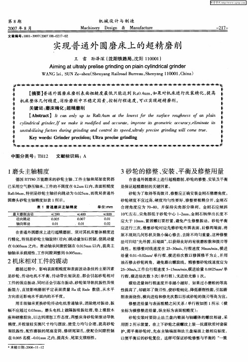
STR/03/024/MTUltra Precision Grinding of Fibre Optic ConnectorsH. Huang, W. K. Chen, L. Yin, Z. J. Xiong, Y. C. Liu and P. K. TeoAbstract – The present paper reports on the development of an ultra precision grinding tech-nology using inclined resin bond diamond cupwheels for machining spherical end faces of fi-bre optic connectors. The ground spherical endfaces obtained using the wheel of grit size of 4 µm have an average roughness (R a) value of ~7 nm in the fibre area and a profile error of below 0.4 µm. The corresponding average return andinsertion losses are ~55 dB and 0.1 dB respec-tively. The results are competitive to those ob-tained from the polishing process that is cur-rently used in industries. Furthermore, this studyhas revealed the relationships between theground surface quality characterised by rough-ness and profile accuracy and the optic per-formance evaluated by insertion and returnlosses.Keywords: Cup wheel grinding, Fibre connector, Surface quality, Tool wear, Insertion loss, Return loss1 BACKGROUNDFibre optic connectors are one of the basic components in optic communication [1]. There exist many types of connectors. The commonly used connector consists of a zirconia ferrule, a glass fibre and a connector body. The fibre is centred inside the ferrule which has a spherical face at its open end. After assembly, the fibre protrudes from the spherical end face of the fer-rule. The spherical end face, together with the fibre, has to be polished to achieve an extremely even and smooth surface. However, there are some problems encountered in the current pol-ishing processes. Typically, it is difficult to con-trol end face profile accuracy during polishing because of the use of flat polishing pads.Ultra-precision grinding is a proven technology for high dimensional accuracy and mirror sur-face finish [2-7]. This technology has been ex-tensively used as a final finishing process for numerous optic products [4-5]. It is thus possible to use the “one-step” ultra precision grinding to replace the current polishing for machining spherical fibre connector end faces. If the “one-step” grinding technology is feasible, the cycle time for machining fibre end face could be short-ened. Moreover, grinding has an advantage over polishing for maintaining the profile accuracy of racy of end faces. The development of ultra pre-cision grinding technology for machining fibre end faces was started in the late of 1980’s. Kariki-Doy et al. [8] developed an automatic ma-chine for grinding fibre connector end faces. It was reported that the machining time for each end face was 2 to 5 min and the achieved inser-tion and return losses were 0.1 dB and 40 dB, respectively. Kanda et al. [9] also studied sur-face grinding technology for fabrication of fibre end faces. They have achieved a surface roughness of 60 nm in R max and thus a better average return loss of 47 dB. Their results need further improvement for the high quality prod-ucts, such as those used for long distance communications. In addition, these earlier stud-ies focused more on the development of grind-ing technology and lacked systematic investiga-tion of effect of surface quality on the return and insertion losses.2 OBJECTIVEIn this project, an ultra precision grinding tech-nology will be developed using inclined resin bond diamond cup wheels for machining the spherical end faces of fibre connectors. In the first part, the effects of grinding conditions on ground surface finish and profile accuracy were systematically investigated. The tool wear and its effect on grinding quality were also dis-cussed. In the second part, the relationship be-tween the ground surface quality, characterised by surface roughness, profile radius and form error, and the optic performance, evaluated by insertion and return losses, was established.3 METHODOLOGY3.1 Fibre connector and its machiningrequirementsAs illustrated in Fig. 1, the fibre optic connectors to be machined in this study consist of a ferrule with a diameter of 2.5 mm and a fibre of 125 µm in diameter. The materials for ferrule and fibre are partially stabilised zirconia and silica, respectively. The ferrules were fabricated by powder injection moulding.Fig. 1. Illustration of a fibre optic connector.3.2 Grinding experimentsGrinding of fibre connector end faces was com-pleted on a CNC grinding machine (Loh Sphe-romatic 25-2SL, Germany). A cup wheel grind-ing method [10-11] was used to generate the spherical profile of end faces. In this method, the cup wheel was tilted and the top part of the tilted wheel contacted the workpiece during grinding, as shown in Fig. 2(a). The radius of the generated convex spherical surface, R, can be expressed as [11],ααsin 2sin 2r D R m −= (1) where r is the lip radius of the cup wheel illus-trated in Fig. 2(b), α the tilt angle and 2/)(i o m D D D += (2)where D i and D o are the cup wheel inner andouter rim’s diameters, respectively.Fig. 2. (a) Schematic illustration of convex spherical surface generation using a cup wheel (b) Detailedwheel lip.During grinding coolant was supplied to the grinding area. Various wheel speed and feedrate were used to examine their effects on ground surface quality. The total feed was fixedat 30 µm. Under each grinding condition three connectors were ground. Spark-out was carriedout at the end of each grinding cycle at the samegrinding speed for ten seconds. Detailed ma-chining conditions are listed in Table 1.As shown in Table 1, the resin bond diamond wheels of different grit sizes were used in the experiments. A medium grade of wheel hard-ness (Grade N) was selected in order to obtain a reasonably good self-dressing. This was taken the consideration of that the combination mate-rials of zirconia (relatively ductile) and silica (brit-tle) need to be ground simultaneously. Prior to grinding, the resin bond diamond wheels were trued and dressed using a cast iron lapping plate. After truing, an alumina paste of grit size of 3 µm was used to dress the wheels until a satisfactory wheel topography was achieved. Oil was used as a lubricant for dressing to reduce abrasive pull-outs. It takes a few minutes for the whole dressing process.Table 1. Grinding conditions.Parameter ValueGrinding wheel Diamond abrasives,resin bond, concentra-tion of 25%Grit size (µm)4, 20Wheel speed (m/s) 2, 6, 10, 14, 18, 22, 26Work speed (m/s) = 0.023 times wheel speedFeed rate (µm/min.) 10, 50 Total feed (µm) 30 3.3 Measurement and characterisation Surface roughness of the ground end faces was measured using a WYKO White Light Interfer-ometer. Radius and form errors of spherical end faces were measured using a Form Talysurf Profilometer (Taylor Hobson). Grinding wheel topography was examined using a Leica Cam-bridge scanning electron microscope (SEM). Insertion and return losses of the machined connectors were measured using a loss tester (EXFO LTS-3900). 4RESULTS & DISCUSSION 4.1 Grindabilitystudy 4.1.1 Effect of wheel grit size Resin bond diamond wheels were selected for the work because this type of wheels has been proven to be the best choice for mirror surface ConnectorαD iR D o(a)r (b)finish of optic components [4-5]. To select a suitable grit size, two wheels of different grit sizes of 4 and 20 µm were tried. Fig. 3 shows the WYKO images of ground surfaces obtained using the two different wheels, indicating the influence of wheel grit size on surface finish. Apparently, the surface generated using the wheel with a grit size of 4 µm. Fig. 3(a) is much smoother than that with a grit size of 20 µm Fig. 3(b).The profile accuracy of the ground end faces was measured using the Talysurf Profilometer. Using the least square arc fitting method, the radius and form error can be obtained from the traced profile. The average profile errors (peak to valley value) for the wheels of grit sizes of 4 and 20 µm are 0.22 and 0.25 µm, respectively. This indicates that the grit size has little influ-ence on the profile accuracy.Fig. 3. WYKO 3D images of specimens ground using wheels with grit sizes of (a) 4 µm and (b) 20 µm. Grinding speed and feed rate are 26 m/s and 10 µm/min, respectively.A more systematic experiment was completed to examine the effect of grit size on the ground sur-face finish. For each grinding speed, three con-nectors were ground. The average values of the three ground specimens are shown in Fig. 4. The lower and upper error bars represent the minimum and maximum values among the three data, respectively. This rule is also applied to Figs. 5-7. It can be seen that for various grinding speeds, the smaller grit size wheel has pro-duced a much better surface finish, which met the required roughness requirement of < 50 nm in R a. This wheel was thus selected for further parametric studies.Fig. 4. Effect of wheel grit size on surface roughness of (a) fibre and (b) ferrule.4.1.2 Effect of grinding speedFigs. 5 and 6 show the effects of grinding speed on the surface roughness, profile radius and form error for the wheel with grit size of 4 µm. Under the grinding conditions selected in this study, the surface finish in the fibre area is much better than that in the ferrule area, as shown in Fig. 5. The machining responses to the selected grinding conditions are apparently in favor of meeting the final quality requirements as only the surface finish of the fibre area will signifi-cantly affect the return and insertion losses. In general, the wheel speed shows little influence on the roughness for either fibre or ferrule. Nev-ertheless, an increase in wheel speed leads to a slight decrease in surface roughness of the fibre region.Fibre: R a = 6.81 nmFerrule: R a = 30.4 nm (a) Fibre: R a = 30.88 nmFerrule: R a = 69.09 nm (b)102030400510********Sur faceRoug hness,Ra(nm)Grinding Speed (m/s)204060800510******** Sur faceRoug hness,Ra(nm)Grinding Speed (m/s)102030405060051015202530Su r f a c e R o u g h n e s s , R a (n m )Grinding Speed (m/s)1617181920212200.20.40.60.81051015202530R a di u s o f G ro u n d P r o f i l e (m m )P VV a l u e o f G r o un d P r o f i l e (µm )Grinding Speed (m/s)10203040051015202530S u r f a c e R o u g h n e s s , R a (n m )Grinding Speed (m/s)Fig. 5. Effect of grinding speed on surface rough-ness.The effects of grinding speed on the profile ra-dius and the form accuracy are shown in Fig. 6. It is also observed that the speed has little influ-ences on either profile radius or form error in terms of PV (peak to valley) values. The form errors achieved for the 4 µm grit size wheel are all below 0.6 µm, giving an average value of about 0.3 µm. The fitted radius of the spherical end faces ranges from 19.5 to 20.3 mm.Fig. 6. Effect of grinding speed on fitted radius and form error of ground profiles.4.1.3 Effect of feed rateFig. 7 shows the effect of feed rate on surface roughness in the fibre area. It is seen that smaller feed rate results in a better surface fin-ish. There exist some exceptions in Fig. 7. At the two highest grinding speeds of 22 and 26 m/s, the surface roughness values for the feed rate of 50 µm/min are even slightly better than those obtained for the feed rate of 10 µm/min. How-ever, the respective roughness values in the ferrule area are near the critical value of 50 nm. It is impractical to further reduce the feed ratebecause the feed rate directly influences the cycle time. In this study, we also aim at a ma-chining time of about 3 minutes for one end face. This requires a feed rate to be at least 10 µm/min. The effects of feed rate on the profile errors and radius are not significant and thus not demonstrated here.Fig. 7. Effect of feed rate on fibre surface roughness.4.2 Repeatability and tool wear studyTo examine the repeatability of grinding results and the effect of tool wear on surface quality, a set of experiments was carried out. As dis-cussed earlier, the wheel of a grit size of 4 µm gives a much better surface quality than that of 20 µm. Thus, this wheel was selected for re-peatability study. The grinding speed and the feed rate were 26 m/s and 10 µm/min., respec-tively. During the experiment, the wheel was trued and dressed prior to grinding and was then used for continuous grinding until obvious wear evidence was observed. The profile radius and the form error of the ground end faces are plot-ted against the connector number machined in Fig. 8. It can be seen that as the machining pro-gresses, the profile radius is slightly increased at a rate of 0.029 mm per machined part (from part no. 1 to 18), as shown in Fig. 8(a). There is a sharp increase when the machined connector number reaches 19. After that the increasing rate (of 0.074 mm per part) in radius is also greater. In accordance with the sharp increase in radius, the PV value of form error also has a much faster increase starting at the number of 20, as shown in Fig. 8(b). Before that, the profile error remains constant. However, it was found that the wheel wear has little influence on the surface roughness. Apparently, the wheel wear becomes significant and loses its shape after grinding 18 end faces. Further continuation of grinding results in a significant increase in radius and form error. It is thus recommended that theoptimal connector number before redressing the wheel is 18.Fig. 8. Effect of wheel wear on profile radius and form error of the end faces.The effect of wheel wear on the profile radius can be explained using the geometrical illustra-tion shown in Fig. 2. It is assumed that there is a wheel wear of ∆r along the lip radius, which re-sults in a reduction in lip radius. From Eq. 1, it is derived that the lip radius reduction (r-r ∆) re-sults in an increase in profile radius. The new profile radius, R', can thus be approximately de-scribed as follows,r R r r D R m ∆+=∆−−=ααsin 2sin )(2' (3)From Eq. 3, it is clearly seen that the wheel wear directly affects the radius of the generated pro-file, which is in good agreement with the result in Fig. 8(a).Fig. 9 shows the wheel surface characteristics of grit size of 4 µm before and after grinding. It is observed in Fig. 9(a) that the abrasive grains before grinding are sharp. The flatted areas were built on the grains after a certain time of grinding, as shown in Fig. 9(b). Pores and loos-ened abrasive grains are also observed, asshown in Fig. 9(b), indicating that pull-outs oc-curred or would occur in the subsequent grind-ing.Fig. 9. Topography of Wheel with grit size of 4 µm (a) before and (b) after grinding.To prolong the wheel life, in our grinding ex-periments the wheels were trued to have profiles with a larger lip radius shown in Fig. 10, com-pared with the conventional one shown in Fig. 2(b). For wheels with the same manufacturing dimensions, a larger lip radius has increased the wheel functional area, thus reduced the wear along the radius direction. The results shown in Fig. 8 were obtained using this method.Fig. 10. Schematic illustrations of the large lip radiuscup wheel used.192021220510********R a d i u s o f F i br e E n d F a c e (m m )Fibre End Faces Machined00.20.60.8051015202530PVV al u eo f E n d F a c e P r o f i l e (µm )Fibre End Faces Machined (a)(b) rαtdR4.3Effect of ground surface quality onreturn and insertion lossesFibre optic connectors are used for interconnec-tion of various components and devices in anoptic fiber system, which play a vital role on sys-tem performance. Two parameters are oftenused to evaluate the quality of the machined connectors, i.e. insertion loss and return loss.While insertion loss predicts directly the powerloss caused by a connector, return loss charac-terises its influence on the system performancesuch as noise and interference. Insertion loss,IL, defines the system’s power budget and thesystem margin, which can be written as:)(log 10IL 21P P10= (4)where P 2 is the initial power and P 1 the powerafter the connector is applied. IL < 0.3 dB is usually required for long-haul telecommunica-tions and < 0.75 dB for local area networks. Re-turn loss, RL, measures the total fractional power that is reflected from a test device, which is defined as)(log 10RL back in P P 10=where P in is the input power and P back the re-flected power. The return loss is normally ~55dB for an ultra polished physical contact (UPC)connector.There are many factors that cause losses in fi-bre optic communications, including end surface Fresnel reflection, separation between two con-nectors, lateral misalignment, angular misalign-ment, mismatch in diameters of core and clad-ding, refractive index profile difference and fiber end preparation. Apparently, the surface finish and the profile accuracy of the end faces are key parameters to evaluate the fibre end prepara-tion.To establish the relationships between the sur-face roughness and the two loss parameters, a set of experiments was completed to obtain the end faces with various surface roughness val-ues. The end faces with large roughness values shown in Fig. 11 were intentionally generated to examine the effect of surface roughness. Under normal grinding conditions with the wheel of a grit size of 4 µm, the ground surface finish could not be so rough. The influences of surface roughness of the end faces in the fibre area on insertion and return losses are shown in Fig. 11(a) and Fig. 11(b), respectively. In Fig. 11(a), it is seen that when the surface roughness val-ues are below ~60 nm, all the insertion losses are below 0.3 dB. The average value for the data below 0.3 dB is 0.1 dB. There is a poor cor-relation between the insertion loss and the roughness for those data. However, when the roughness values are above ~60 nm, an in-crease in roughness value results in a greater insertion loss. Surface roughness has a much more influence on return loss than on insertion loss. As can be seen in Fig. 11(b), an increase in surface rough-ness leads to a significant decrease in return loss, when the surface roughness is below 50 nm. Above this value, the influence becomes much less, implying that the surface Fresnel reflection becomes dominant. It is also seen that the surface roughness required for meeting the return loss target is below 20 nm in R a , much lower than the R a value for insertion loss (~60 nm). Fig. 11. Relationship between surface roughness and (a) insertion loss and (b) return loss.The data in Fig. 8 was also used to examine the effects of profile radius and form error on inser-tion and return losses. It was found that there is a poor correlation between profile radius and either insertion or return loss. Though the re-10203040506070050100150200250Re t u r n L o s s (d B )Surface Roughness, Ra (nm)0.00.501.01.5050100150200250I n s e rt i o n L o s s (d B )Surface Roughness, Ra (nm)quired nominal radius is 20 mm, a variation of radius from 19.5 to 21 mm has little influence on the insertion or return loss. Similarly, it is difficult to relate the profile accuracy of ground end faces to the insertion or return loss. This is probably because the profile error variation in Fig. 8 is too small to see its influence on inser-tion and return losses. The above results sug-gest that the influence of profile radius and error is not significant on the optic performance of fibre connectors.4.4 Comparison between grinding andpolishingTwo typical microscopic images of the ground and polished end faces are shown in Fig. 12. The surface finishes in the ground and polished fibre areas looks similar. The average value of surface roughness (R a) in the fibre area for the ground end faces is 6.9 nm, which is close to the roughness of 4.8 nm from polishing. However, the surface finishes in the ferrule area for the two processing methods are quite different. The ground ferrule surface (R a = ~30 nm) is much rougher than the polished one (R a = ~10 nm). Nevertheless, the ground connectors performed better than those polished in terms of insertion and return losses. This should be attributed to the much better profile accuracy obtained from the grinding process. The result also indicates that the surface finish in the fibre area has a dominant influence on the two optic parameters. Fig. 12. Comparison of (a) ground and (b) polished end faces. The yield obtained from the grinding process was 100%, in contrast to the 80% from the pol-ishing process. Apparently, the grinding process can produce a controlled end face profile, and thus a consistent quality in terms of the optic performance. However, during polishing the end face profile is difficult to be controlled. This re-sults in an inconsistent quality and thus a lower yield than grinding. It is worthy to point out that the cycle time calculated for polishing is based on the fact that only one connector was ma-chined each cycle. In fact, the modern polishing machines can process at least 12 connectors simultaneously. Therefore, the machining cycle time is more than 12 times shortened. However, this low efficiency problem can be solved by de-veloping a specially designed machine for grind-ing multiple connectors, as indicated in [8].5 CONCLUSIONUltra precision grinding using resin bond dia-mond cup wheels has been successfully devel-oped for machining spherical end faces of fibre connectors. The ground spherical end faces ob-tained using the wheel of grit size of 4 µm have an average value of R a of ~ 6.9 nm in the fibre area and a profile error of below 0.4 µm for the entire surface. These correspond to an average return loss of ~ 55 dB and insertion loss of 0.1 dB. The comparison between grinding and pol-ishing has demonstrated that both methods can achieve similar optic performance in processing fibre optic connectors, and the former is more consistent.It is found that the influence of grinding speed on surface finish and profile accuracy is not signifi-cant. However, the feed rate or the wheel grit size significantly affects the ground surface roughness, but not the profile accuracy. There exist relationships between ground surface roughness and insertion or return losses. A rougher end face certainly results in larger inser-tion loss and smaller return loss, which would worsen optic system performance. The industrial requirement on insertion loss can be easily achieved with the roughness below 60 nm, while that on return loss requires a roughness of be-low 20 nm.6 INDUSTRIALSIGNIFICANCEThe optics/photonics industry has a huge global market and is expected to surge to US$700 billion in 2025. Singapore is now tapping about S$2 billion in optics-related business. USA and Europe are the major players, followed by markets in China, Japan and Taiwan. Singapore50 µm Ferrule(a)(b)is one of the first countries in Southeast Asia to see its growth potential and is quickly adopting new technologies and creating new platforms for training and R&D to spearhead the growth. Local companies, have approached SIMTech for new technologies on fibre/ferrule connector machining. The technologies developed in this project should be transferred into industries in the near future when the photoics business picks up, making a direct impact on Singapore economy.REFERENCES[1] D. Derickson, Fibre Optic Test and Meas-urement, Prentice Hall PTR, New Jersey,USA, (1998).[2] H. Ohmori and T. Nakagawa, “Mirror sur-face grinding of silicon wafers with electro-lytic in-process dressing”, Annals of CIRP,Vol. 39(1), pp. 329-332, (1990).[3] D.J. Stephenson, D. Veselvovac, S. Manleyand J. Corbett, “Ultra precision grinding ofhard steels”, Precision Engineering, Vol. 25,pp. 336-345, (2001).[4] S. Masaru, T. Kuriyagawa, J.S. Lee and K.Syoji, “Machining of aspherical opto-deviceutilizing parallel grinding method”, Proceed-ings of the 16th ASPE Annual Meeting, Vir-ginia, 10-15 November 2001, pp. 433-436. [5] Y. Namba, H. Kobayashi, H. Suzuki and K.Yamashita, “Ultraprecision surface grindingof chemical vapor deposited silicon carbidefor X-ray mirrors using resinoid bonded dia-mond wheels”, Annals of CIRP, Vol. 48(1),pp. 277-280, (1999).[6] H. Ohmori, W. Li, A. Makinouchi and B.P.Bandyopadhyay, “Efficient and precision grinding of small hard and brittle cylindricalparts by the centreless grinding process combined with electro-discharge truing andelectrolytic in-process dressing”, Journal ofMaterials Processing Technology, Vol. 98, pp. 322-327, (2000).[7] E.S. Lee, “A study of the development of anultraprecision grinding system for mirror-likegrinding”, International Journal of AdvancedManufacturing Technology, Vol. 16, pp. 1-9,(2000).[8] T. Karaki-Doy, T. Saitou, J. Watanabe andK. Matsunaga, “Development of a new automatic processing machine for optical fi-bre connector ends”, Bulletin of Japan Soci-ety of Precision Engineering, Vol. 22, pp.216-222, (1988).[9] T. Kanda, M. Mitsuhashi, T. Ueda, A. Toyo-hara and K. Yamamoto, “New mirror finishsurface grinding technology for the fabrica-tion of optical device endfaces”, Proceed-ings of SPIE, Vol. 2576, pp. 84-91, (1995). [10] H. Suzuki, T. Kuriyagawa, K. Syoji and K.Tanaka, “Study on ultra-precision grinding ofmicro aspherical surface (3rd report) – minia-turization of aspherical surface in inclined ro-tational grinding”, Bulletin of Japan Societyof Precision Engineering, Vol. 64, pp. 1350-1354, (1998).[11] G.E II Storz and T.A. Dow, “Cup wheelgrinding geometry”, Proceedings of the 9thASPE Annual Meeting, Ohio, 2-7 October 1994, pp. 105-108.。