EZ Controller
CX3技术参考手册
EZ-USB® CX3 Technical Reference Manual,Doc. No. 001-92471 Rev. **
5
赛普拉斯 EZ-USB CX3
1.3
框图
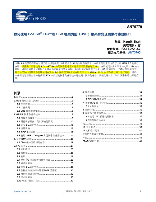
图 4:系统框图
Data Lanes CX3 USB Host
图4显示了一个典型系统的详细框图,其中通过CX3将数据从图像传感器传输到USB主机。
EZ-USB® CX3 Technical Reference Manual,Doc. No. 001-92471 Rev. **
4
赛普拉斯 EZ-USB CX3
1.2
CX3 特性
CX3 支持以下特性: USB 3.0 和 USB 2.0 外设控制器与 USB 3.0 规范 1.0 相兼容 MIPI CSI-2 RX 接口 o o o MIPI CSI-2 兼容(版本 1.01 修订版 0.04 — 2009 年 4 月 2 日) 支持多大四个通道;每个通道的传输速度可达 1 Gbps 支持用于配置图像传感器的摄像机控制接口(通过 I C)
2
支持下面的视频数据格式 o o o o RAW 8/10/12/14 YUV 422(8/10 位) RGB 888 / 666 / 565 用户定义的 8 位
12 个 GPIO,用于控制摄像机相关功能(如照明、同步输入、同步输出,等等) 与 FX3 相同,该器件也支持 I C、SPI、I S 输出和 UART 接口 用于调试的 JTAG 接口
SSRXSSRX+ SSTXSSTX+ DD+
I2C_SCL
I2C_SDA
I2C
UART
SPI
GPIOs
PreSonus ATOM SQ 控制器使用指南说明书

Production and Performance Pad ControllerGetting Started • Erste Schritte • Cómo empezar • Pour commencer • 开始登录, 注册序列号。
要先将其连接到可用的电脑USB接口。
无需安装驱动器。
连接到Studio One和Ableton Live后,特种作业会自动进行。
更多信息请访问, 阅读ATOM SQ操作手册。
™Screen Controls • Controles de la pantalla • Screen-Bedienelemente • Commandes d‘écran • 屏幕控制。
Use the encoder to change parameter values. Press the button above or below aparameter to change the value. Use the left and right arrow buttons to go to the next orprevious screen for any of the menu options.Utilice el codificador para cambiar los valores de los parámetros. Pulse el botón encimao debajo de un parámetro para cambiar el valor. Utilice los botones de flecha izquierda yderecha para ir a la pantalla siguiente o anterior para cualquiera de las opciones de menúÄndern Sie Parameter-Werte mit dem Endlosregler. Drücken Sie die Taste über oder untereinem Parameter, um den Wert zu ändern. Mit den rechten und linken Pfeiltasten blätternSie in den Menüoptionen vor- und zurück.Utilisez l’encodeur pour changer les valeurs de paramètre. Pressez la touche au-dessus ouau-dessous d’un paramètre pour changer de valeur. Utilisez les touches flèches gauche etdroite pour passer à l’écran précédent ou suivant de n’importe quelle option du menu使用编码器更改参数。
如何使用EZ-USB
文档编号:001-92220 修订版**
2
如何使用 EZ-USB® FX3™在 USB 视频类别(UVC)框架内实现图像传感器接口
3. 构建一个 DMA,它会将来自 GPIF II 模块上图像传感器 的数据转移到 USB 接口模块( UIB )内。在本应用 中,必须将头数据添加到图像传单器内的视频数据中, 以符合 UVC 规格的要求。因此应配置 DMA,以允许 CPU 将所需的头数据添加到 DMA 缓冲区内。该通道 必须设计使最大带宽满足将视频从图像传感器输送到 PC 的要求。有关详细信息,请参考第 4 节中的内容。 2 4. 使用 FX3 I C 主控来控制图像传感器的总线。通过赛普 2 拉斯的标准库调用可对 I C 和 GPIO 单元进行编程,有 关内容在第 5.4 节中进行了介绍。
图 2. 系统框图
USB Host USB Bulk IN EP USB3 Video Control USB EP0 Video Data FX3 PCLK Frame Valid DMA Channel Data GPIF II Line Valid Data bus Reset# Image Sensor
®
文档编号:001-92™在 USB 视频类别(UVC)框架内实现图像传感器接口
1. 简介
USB 3.0 提供的高带宽对用于将外设连接至 USB 的各个 IC 提出很高的要求。一个流行的示例就是摄像头将非压缩数据 输送到 PC 中。在本应用笔记中,通过使用赛普拉斯的 EZ® USB FX3™ 芯片可以实现转换器的功能,该转换器的一端 连接到图像传感器,另一端则通过 USB 3.0 连接至主机 PC。FX3 使用它的第二代通用可编程接口(GPIF II)来提 供图像传感器接口,并通过其超速 USB 单元连接至 PC。 FX3 固件将来自图像传感器的数据转换为符合 USB 视频类 (UVC)的格式。符合此类别的摄像设备能够使用 OS 内 置的驱动程序进行操作,使摄像头与主机应用(如 AMCap 和 VLC 媒体播放器)相互兼容。 图 1. 摄像头应用
用EZ-USB FX3 在USB视频类别UVC框架内实现图像传感器接口
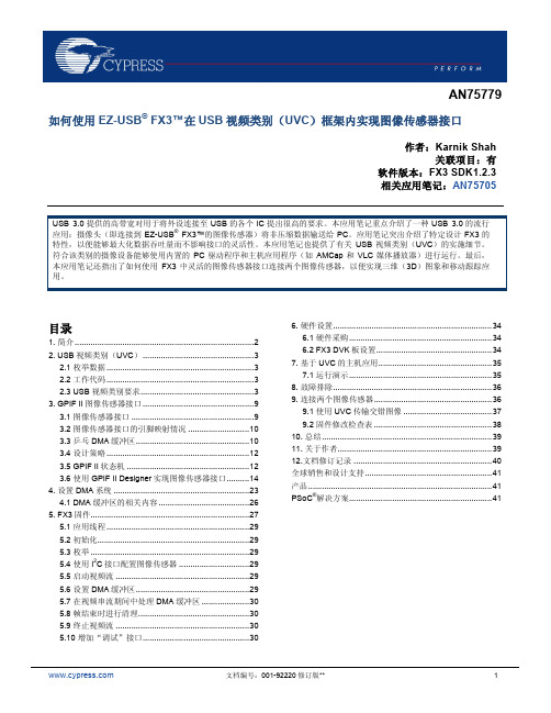
图 1 描述的是摄像头应用。左侧是一个带有超速 USB 3.0 端口的 PC ,而右侧是一个具有下面各项特性的图像传感 器:
8 位同步并行数据接口 每个像素为 16 位 YUY2 颜色空间 分辨率为 1280 x 720 个像素(720p) 30 帧每秒 帧/行有效信号均为高电平有效 正向时钟边沿极性
图 2. 系统框图
USB Host USB Bulk IN EP USB3 Video Control USB EP0 Video Data FX3 PCLK Frame Valid DMA Channel Data GPIF II Line Valid Data bus Reset# Image Sensor
Image Sensor
Host PC
USB 3.0
Converter (FX3)
Clock Sync Data[7:0] Control (I2C)
即使应用笔记讨论了一个特定的图像传感器接口,上面所述 的是多种图像传感器接口的通用特性,即使可能有轻微差 异,如数据总线宽度和信号极性。基于 GPIF II 模块的可编 程性质,这些变化很容易作出调节适应。此外, FX3 会使 2 用其 I C 接口实现控制总线,用作配置图像传感器。 图 2 显示的是系统框图更加详细的信息。为框图的主要子 模块进行编号,这些任务由下述的各个子模块执行:
®
文档编号:001-92220 修订版**
1
如何使用 EZ-USB® FX3™在 USB 视频类别(UVC)框架内实现图像传感器接口
1. 简介
USB 3.0 提供的高带宽对用于将外设连接至 USB 的各个 IC 提出很高的要求。一个流行的示例就是摄像头将非压缩数据 输送到 PC 中。在本应用笔记中,通过使用赛普拉斯的 EZ® USB FX3™ 芯片可以实现转换器的功能,该转换器的一端 连接到图像传感器,另一端则通过 USB 3.0 连接至主机 PC。FX3 使用它的第二代通用可编程接口(GPIF II)来提 供图像传感器接口,并通过其超速 USB 单元连接至 PC。 FX3 固件将来自图像传感器的数据转换为符合 USB 视频类 (UVC)的格式。符合此类别的摄像设备能够使用 OS 内 置的驱动程序进行操作,使摄像头与主机应用(如 AMCap 和 VLC 媒体播放器)相互兼容。 图 1. 摄像头应用
Cypress EZ-USB FX技术参考手册说明书

EZ-USB FX Technical ReferenceManual• Cypress Semiconductor • Interface Products Division • • 15050 Avenue of Science • Suite 200 • San Diego, CA 92128 •Cypress Disclaimer AgreementThe information in this document is subject to change without notice and should not be con-strued as a commitment by Cypress Semicon-ductor Corporation Incorporated. While reasonable precautions have been taken, Cypress Semiconductor Corporation assumes no responsibility for any errors that may appear in this document.No part of this document may be copied or reproduced in any form or by any means with-out the prior written consent of Cypress Semi-conductor Corporation.Cypress Semiconductor products are not designed, intended, or authorized for use as components in systems intended for surgical implant into the body, or other applications intended to support or sustain life, or for any other application in which the failure of the Cypress Semiconductor product could create a situation where personal injury or death may occur. Should Buyer purchase or use Cypress Semiconductor products for any such unin-tended or unauthorized application, Buyer shall indemnify and hold Cypress Semiconductor and its officers, employees, subsidiaries, affili-ates and distributors harmless against all claims, costs, damages, expenses, and rea-sonable attorney fees arising out of, directly or indirectly, any claim of personal injury or death associated with such unintended or unautho-rized use, even if such claim alleges that Cypress Semiconductor was negligent regard-ing the design or manufacture of the part.The acceptance of this document will be con-strued as an acceptance of the foregoing con-ditions.Chapter 16, 17, and 18 of this databook con-tain copyrighted material that is the property of Synopsys, Inc., © 1998, ALL RIGHTS RESERVED.The EZ-USB FX Technical Reference Manual, Version 1.2.Copyright 2000, Cypress Semiconductor Cor-poration.All rights reserved.Table of ContentsChapter 1. Introducing EZ-USB FX - - - - - - - - - - - - - - - - - - - - 1-11.1 Introduction...................................................................................................1-11.2 EZ-USB FX Block Diagrams.........................................................................1-21.3 The USB Specification..................................................................................1-31.4 Tokens and PIDs...........................................................................................1-41.5 Host is Master................................................................................................1-51.5.1 Receiving Data from the Host.............................................................1-51.5.2 Sending Data to the Host....................................................................1-61.6 USB Direction................................................................................................1-61.7 Frame.............................................................................................................1-61.8 EZ-USB FX Transfer Types..........................................................................1-61.8.1 Bulk Transfers.....................................................................................1-71.8.2 Interrupt Transfers...............................................................................1-71.8.3 Isochronous Transfers........................................................................1-71.8.4 Control Transfers...............................................................................1-81.9 Enumeration..................................................................................................1-81.10 The USB Core..............................................................................................1-91.11 EZ-USB FX Microprocessor.....................................................................1-101.12 ReNumeration™........................................................................................1-111.13 EZ-USB FX Endpoints...............................................................................1-111.13.1 EZ-USB FX Bulk Endpoints............................................................1-121.13.2 EZ-USB FX Control Endpoint Zero.................................................1-121.13.3 EZ-USB FX Interrupt Endpoints......................................................1-131.13.4 EZ-USB FX Isochronous Endpoints................................................1-131.14 Interrupts...................................................................................................1-131.15 Reset and Power Management................................................................1-141.16 Slave FIFOs................................................................................................1-141.17 GPIF (General Programmable Interface).................................................1-141.18 EZ-USB FX Product Family......................................................................1-15iiiTable of Contents(Table of Contents)Chapter 2. EZ-USB FX CPU - - - - - - - - - - - - - - - - - - - - - - - - 2-12.1 Introduction...................................................................................................2-12.2 8051 Enhancements.....................................................................................2-12.3 EZ-USB FX Enhancements..........................................................................2-22.4 EZ-USB FX Register Interface .....................................................................2-22.5 EZ-USB FX Internal RAM..............................................................................2-32.6 I/O Ports.........................................................................................................2-32.7 Interrupts.......................................................................................................2-42.8 Power Control...............................................................................................2-52.9 SFRs...............................................................................................................2-52.10 Internal Bus.................................................................................................2-72.11 Reset............................................................................................................2-7Chapter3. EZ-USB FX Memory - - - - - - - - - - - - - - - - - - - - - - 3-13.1 Introduction...................................................................................................3-13.2 8051 Memory.................................................................................................3-23.2.1 About 8051 Memory Spaces ..............................................................3-23.3 Expanding EZ-USB FX Memory...................................................................3-43.4 CS# and OE# Signals ...................................................................................3-5Chapter4. EZ-USB FX Input/Output - - - - - - - - - - - - - - - - - - - 4-14.1 Introduction...................................................................................................4-14.2 I/O Ports.........................................................................................................4-24.3 Input/Output Port Registers.........................................................................4-44.4 Port Configuration Tables............................................................................4-84.5 I 2C-Compatible Controller..........................................................................4-144.6 8051 I 2C-Compatible Controller.................................................................4-144.7 Control Bits.................................................................................................4-164.7.1 START..............................................................................................4-164.7.2 STOP................................................................................................4-164.7.3 LASTRD...........................................................................................4-174.8 Status Bits...................................................................................................4-174.8.1 DONE ...............................................................................................4-174.8.2 ACK..................................................................................................4-174.8.3 BERR................................................................................................4-174.8.4 ID1, ID0............................................................................................4-18Table of Contentsiii(Table of Contents)4.9 Sending I 2C-Compatible Data ....................................................................4-184.10 Receiving I 2C-Compatible Data................................................................4-184.11 I 2C-Compatible Boot Loader ....................................................................4-194.12 SFR Addressing........................................................................................4-214.13 SFR Control of PORTs A-E.......................................................................4-25Chapter5. EZ-USB FX Enumeration & ReNumeration™ - - - - - - - - - 5-15.1 Introduction...................................................................................................5-15.2 The Default USB Device ...............................................................................5-25.3 USB Core Response to EP0 Device Requests...........................................5-35.3.1 Port Configuration Bits........................................................................5-45.4 Firmware Load...............................................................................................5-55.5 Enumeration Modes.....................................................................................5-65.6 No Serial EEPROM........................................................................................5-75.7 Serial EEPROM Present, First Byte is 0xB4...............................................5-85.8 Serial EEPROM Present, First Byte is 0xB6...............................................5-95.9 Configuration Byte 0..................................................................................5-105.10 ReNumeration™........................................................................................5-115.11 Multiple ReNumeration™.........................................................................5-135.12 Default Descriptor.....................................................................................5-13Chapter6. EZ-USB FX Bulk Transfers - - - - - - - - - - - - - - - - - - 6-16.1 Introduction...................................................................................................6-16.2 Bulk IN Transfers ..........................................................................................6-46.3 Interrupt Transfers........................................................................................6-56.4 EZ-USB FX Bulk IN Example........................................................................6-56.5 Bulk OUT Transfers ......................................................................................6-66.6 Endpoint Pairing ...........................................................................................6-86.7 Paired IN Endpoint Status............................................................................6-86.8 Paired OUT Endpoint Status........................................................................6-96.9 Reusing Bulk Buffer Memory.......................................................................6-96.10 Data Toggle Control..................................................................................6-106.11 Polled Bulk Transfer Example .................................................................6-116.12 Enumeration Note.....................................................................................6-126.13 Bulk Endpoint Interrupts..........................................................................6-136.14 Interrupt Bulk Transfer Example .............................................................6-14ivTable of Contents(Table of Contents)6.15 Enumeration Note.....................................................................................6-196.16 The Autopointer........................................................................................6-19Chapter7. EZ-USB FX Slave FIFOs- - - - - - - - - - - - - - - - - - - - 7-17.1 Introduction...................................................................................................7-17.1.1 8051 FIFO Access..............................................................................7-27.1.2 External Logic FIFO Access...............................................................7-27.1.3 ASEL, BSEL in 8-Bit Mode.................................................................7-37.1.4 ASEL, BSEL in Double-Byte Mode.....................................................7-47.1.5 FIFO Registers...................................................................................7-47.1.6 FIFO Flags and Interrupts ..................................................................7-57.2 Slave FIFO Register Descriptions...............................................................7-67.2.1 FIFO A Read Data..............................................................................7-77.2.2 A-IN FIFO Byte Count ........................................................................7-87.2.3 A-IN FIFO Programmable Flag...........................................................7-97.2.3.1 Filling FIFO..............................................................................7-107.2.3.2 Emptying FIFO........................................................................7-107.2.3.3 A-IN FIFO Pin Programmable Flag.........................................7-117.2.4 B-IN FIFO Read Data.......................................................................7-137.2.5 B-IN FIFO Byte Count ......................................................................7-147.2.6 B-IN FIFO Programmable Flag.........................................................7-157.2.6.1 Filling FIFO..............................................................................7-167.2.6.2 Emptying FIFO........................................................................7-167.2.7 B-IN FIFO Pin Programmable Flag...................................................7-177.2.8 Input FIFOs A/B Toggle CTL and Flags ...........................................7-187.2.9 Input FIFOs A/B Interrupt Enables ...................................................7-207.2.10 Input FIFOs A/B Interrupt Requests ...............................................7-227.2.11 FIFO A Write Data..........................................................................7-247.2.11.1 A-OUT FIFO Byte Count.......................................................7-257.2.12 A-OUT FIFO Programmable Flag...................................................7-267.2.12.1 Filling FIFO............................................................................7-277.2.12.2 Emptying FIFO......................................................................7-277.2.13 A-OUT FIFO Pin Programmable Flag.............................................7-287.2.14 B-OUT FIFO Write Data .................................................................7-307.2.15 B-OUT FIFO Byte Count ................................................................7-317.2.16 B-OUT FIFO Programmable Flag...................................................7-327.2.16.1 Filling FIFO............................................................................7-337.2.16.2 Emptying FIFO......................................................................7-33Table of Contentsv(Table of Contents)7.2.17 B-OUT FIFO Pin Programmable Flag.............................................7-347.2.18 Output FIFOs A/B Toggle CTL and Flags.......................................7-357.2.19 Output FIFOs A/B Interrupt Enables...............................................7-377.2.20 Output FIFOs A/B Interrupt Requests.............................................7-397.2.21 FIFO A/B Setup...............................................................................7-407.2.22 FIFO A/B Control Signal Polarities..................................................7-437.2.23 FIFO Flag Reset..............................................................................7-447.3 FIFO Timing.................................................................................................7-45Chapter 8. General Programmable Interface (GPIF) - - - - - - - - - - - 8-18.1 What is GPIF?................................................................................................8-18.2 Applicable Documents and Tools ...............................................................8-28.3 Typical GPIF Interface ..................................................................................8-38.4 External GPIF Connections..........................................................................8-48.4.1 The External GPIF Interface ...............................................................8-48.4.2 Connecting GPIF Signal Pins to Hardware.........................................8-58.4.3 Example GPIF Hardware Interconnect ...............................................8-58.5 Internal GPIF Operation................................................................................8-68.5.1 The Internal GPIF Engine ...................................................................8-68.5.2 Global GPIF Configuration..................................................................8-68.5.2.1 Data Bus Width..........................................................................8-68.5.2.2 Control Output Modes ...............................................................8-68.5.2.3 Synchronous/Asynchronous Mode............................................8-78.5.3 Programming GPIF Waveforms..........................................................8-78.5.3.1 The GPIF IDLE State.................................................................8-88.5.3.2 Defining Intervals.....................................................................8-108.5.3.3 Interval Waveform Descriptor..................................................8-148.5.3.4 Physical Structure of the Waveform Memories........................8-188.5.4 Starting GPIF Waveform Transactions .............................................8-208.5.4.1 Performing a Single Read Transaction....................................8-208.5.4.2 Performing a Single Write Transaction....................................8-228.5.5 GPIF FIFO Transactions...................................................................8-228.5.5.1 The GPIF_PF Flag ..................................................................8-228.5.5.2 Performing a FIFO Read Transaction .....................................8-238.5.5.3 Performing a FIFO Write Transaction......................................8-238.5.5.4 Burst FIFO Transactions .........................................................8-248.5.5.5 Waveform Selector..................................................................8-258.5.6 Data/Trigger Registers......................................................................8-26viTable of Contents(Table of Contents)8.5.7 FIFO Operation Trigger Registers....................................................8-288.5.8 Transaction Count Registers............................................................8-298.5.9 READY Register...............................................................................8-308.5.10 CTLOUTCFG Register...................................................................8-318.5.11 IDLE State Registers......................................................................8-328.5.12 Address Register GPIFADRL.........................................................8-348.5.13 GPIF_ABORT Register ..................................................................8-35Chapter 9. EZ-USB FX Endpoint Zero - - - - - - - - - - - - - - - - - - 9-19.1 Introduction...................................................................................................9-19.2 Control Endpoint EP0...................................................................................9-29.3 USB Requests...............................................................................................9-59.3.1 Get Status...........................................................................................9-69.3.2 Set Feature.......................................................................................9-109.3.3 Clear Feature....................................................................................9-129.3.4 Get Descriptor ..................................................................................9-129.3.4.1 Get Descriptor-Device.............................................................9-149.3.4.2 Get Descriptor-Configuration ..................................................9-159.3.4.3 Get Descriptor-String ..............................................................9-159.3.5 Set Descriptor...................................................................................9-169.3.5.1 Set Configuration ....................................................................9-199.3.6 Get Configuration .............................................................................9-199.3.7 Set Interface .....................................................................................9-209.3.8 Get Interface.....................................................................................9-219.3.9 Set Address......................................................................................9-219.3.10 Sync Frame ....................................................................................9-229.3.11 Firmware Load................................................................................9-23Chapter 10. EZ-USB FX Isochronous Transfers - - - - - - - - - - - - 10-110.1 Introduction...............................................................................................10-1 10.2 Isochronous IN Transfers........................................................................10-210.2.1 Initialization.....................................................................................10-2 10.2.2 IN Data Transfers ...........................................................................10-3 10.3 Isochronous OUT Transfers ....................................................................10-310.3.1 Initialization.....................................................................................10-4 10.3.2 OUT Data Transfer.........................................................................10-4 10.4 Setting Isochronous FIFO Sizes..............................................................10-5Table of Contentsvii(Table of Contents)10.5 Isochronous Transfer Speed ...................................................................10-7 10.6 Other Isochronous Registers...................................................................10-910.6.1 Disable ISO.....................................................................................10-9 10.6.2 Zero Byte Count Bits.....................................................................10-10 10.7 ISO IN Response with No Data ..............................................................10-10 10.8 Restrictions Near SOF............................................................................10-11Chapter 11. EZ-USB FX DMA System - - - - - - - - - - - - - - - - - - 11-111.1 Introduction...............................................................................................11-1 11.2 DMA Register Descriptions......................................................................11-211.2.1 Source, Destination, Transfer Length Address Registers...............11-2 11.2.2 DMA Start and Status Register.......................................................11-6 11.2.3 DMA Synchronous Burst Enables Register ....................................11-6 11.2.4 Dummy Register .............................................................................11-9 11.3 External DMA Transfers - Strobes.........................................................11-1011.3.1 Selection of RD/FRD and WR/FWR DMA Strobes .......................11-10 11.4 Interaction of DMA Strobe Waveforms and Stretch Bits.....................11-1011.4.1 DMA External Writes.....................................................................11-11 11.4.2 DMA External Reads.....................................................................11-1211.4.2.1 Modes 0 and 1.....................................................................11-1311.4.2.2 Modes 2 and 3.....................................................................11-13Chapter 12. EZ-USB FX Interrupts - - - - - - - - - - - - - - - - - - - 12-112.1 Introduction...............................................................................................12-1 12.2 USB Core Interrupts..................................................................................12-2 12.3 Resume Interrupt ......................................................................................12-2 12.4 USB Signaling Interrupts..........................................................................12-2 12.5 SUTOK, SUDAV Interrupts.......................................................................12-7 12.6 SOF Interrupt.............................................................................................12-7 12.7 Suspend Interrupt.....................................................................................12-8 12.8 USB RESET Interrupt................................................................................12-8 12.9 Bulk Endpoint Interrupts..........................................................................12-8 12.10 USB Autovectors.....................................................................................12-8 12.11 Autovector Coding................................................................................12-10 12.12 I 2C-Compatible Interrupt.......................................................................12-12 12.13 In Bulk NAK Interrupt............................................................................12-12viiiTable of Contents (Table of Contents)12.14 I 2C-Compatible STOP Complete Interrupt..........................................12-13 12.15 Slave FIFO Interrupt (INT4)..................................................................12-15Chapter 13. EZ-USB FX Resets - - - - - - - - - - - - - - - - - - - - - 13-113.1 Introduction...............................................................................................13-1 13.2 EZ-USB FX Power-On Reset (POR).........................................................13-1 13.3 Releasing the 8051 Reset.........................................................................13-313.3.1 RAM Download...............................................................................13-4 13.3.2 EEPROM Load...............................................................................13-4 13.3.3 External ROM.................................................................................13-4 13.4 8051 Reset Effects....................................................................................13-4 13.5 USB Bus Reset..........................................................................................13-5 13.6 EZ-USB FX Disconnect ............................................................................13-7 13.7 Reset Summary.........................................................................................13-8Chapter 14. EZ-USB FX Power Management - - - - - - - - - - - - - - 14-114.1 Introduction...............................................................................................14-1 14.2 Suspend.....................................................................................................14-2 14.3 Resume......................................................................................................14-3 14.4 Remote Wakeup........................................................................................14-5Chapter 15. EZ-USB FX Registers - - - - - - - - - - - - - - - - - - - 15-115.1 Introduction...............................................................................................15-115.1.1 Example Register Formats .............................................................15-1 15.1.2 Other Conventions..........................................................................15-2 15.2 Slave FIFO Registers................................................................................15-315.2.1 FIFO A Read Data..........................................................................15-3 15.2.2 A-IN FIFO Byte Count ....................................................................15-3 15.2.3 A-IN FIFO Programmable Flag.......................................................15-4 15.2.4 A-IN FIFO Pin Programmable Flag.................................................15-4 15.2.5 B-IN FIFO Read Data.....................................................................15-5 15.2.6 B-IN FIFO Byte Count ....................................................................15-5 15.2.7 B-IN FIFO Programmable Flag.......................................................15-6 15.2.8 B-IN FIFO Pin Programmable Flag.................................................15-6 15.2.9 Input FIFOs A/B Toggle CTL and Flags .........................................15-7 15.2.10 Input FIFOs A/B Interrupt Enables ...............................................15-7 15.2.11 Input FIFOs A/B Interrupt Requests .............................................15-7。
德尔塔电气 DDC-3000 3200 3400 恒温器 产品说明书

SpecificationsAirApprovalsANSI / ASHRAE Standard 130ETL listed to meet requirements of UL 1995 and CSA 236SoundAHRI 880 Certified Box LinersAvailable in fiberglass, foil face, closed cell (EPFI), or metal-linedUL 181 and NFPA 90A compliance Insulation meets ASHRAE 62.1requirements for resistance to mold growth and erosion Welding seamsContinuous welded primary inlet duct to minimize leakage with 3 stiffening beads for added rigidityWaterPressure TestsCoils proof tested at 450 psig and leak tested at 300 psig air pressure under water. Factory pressure tested at 100 psig, shipped with 40-50 psigrecharged, includes gauge to indicate that unit is leak free HydronicsPre-assembled Y-strainer with PT port, drain and isolation valve, ATC valve, manual air vent, union and balancing valve with PT ports H2O CoilCoil Casing- 20 Ga. galvanized steel Coil Tubing- 12.7 mm (0.5 in.) O.D., 0.4 mm copper (0.016 in.) walls Coil Fins- 1.14 mm (0.045 in.) aluminum, 10 fins per inchConstruction22 Ga. galvanized steel casing,mechanically sealed for low leakage with 14 Ga. rigid support handlesNEMA 1 (standard) /UL 508A (optional) certified control enclosureDescriptionThe Zone Control Unit (ZCU) is a complete VAV terminal unit with a Delta Controls controller that is delivered pre-assembled to the job site and ready for immediate installation. Delta controllers are pre-programmed and factory commissioned.ApplicationZCU is a complete pre-engineered VAV bundled solution delivered at a lower installed cost. Ready for immediate installation and designed for standard VAV applications and seismic-sensitive buildings.It serves large zone areas in commercial spaces, such as for e.g. office buildings, to provide fresh air and heating or cooling foroccupants’ comfort and health.FeaturesDesigned to increase the profitability of projects with VAV boxes by lowering the total construction cost and time.Reduces the overall project risk with a single source of responsibility Includes Delta VAV controller, valves, damper, actuators, coil and piping, integrated shipping supports and handlesPre-fabricated wiring harness, UL/ULC 508A listedShipped pressurized with gaugeattached to ensure a leak-free delivery Made-to-order to meet your site’s requirementsZCUDelta Zone Control UnitSpecifications (Continued)ControlsNative BACnet application controllersAmbient0°C to 55°C (32°F to 131°F)10% to 95% RH (non-condensing)PowerDVC-V304- 24 VAC 50/60 Hz @ 15 VA(not including output loading, 52 VAmax with fully loaded TRIAC Outputs)DVC-V304E- 24 VAC @ 15 VA, 60 VA maxwith fully loaded TRIACSDVC-V304-PoE- PoE Power In802.3at PoE: 53 VDC, 25.5 W max802.3af PoE: 48 VDC, 12.95 W maxDVC-V322- 24 VAC 50/60 Hz @ 15 VA (32VA max with fully loaded TRIACOutputs)DVC-V322E- 24 VAC @ 15 VA, 35 VA maxwith fully loaded TRIACSDVC-V322-PoE- PoE Power In802.3at PoE: 53 VDC, 25.5 W max802.3af PoE: 48 VDC, 12.95 W maxeZVP-440 and eZVP-440E- 24 VAC,50/60 Hz, 85 VA max (11 VA excludingTRIAC loading)Typical ZCU Piping ArrangementCopyright © 2020 Delta Controls. All rights reserved.Subject to change without notice.Ordering*******************************************************************.eZNS-T100enteliZONE Network Sensor: LINKnet room stat with multiple display, button, andinput sensor optionsCON-768BT Delta MS/TP to Bluetooth Network ConverterCON-ENOC-868Delta Controls EnOcean Zone Gateway, supporting 32 devices, 868 MHzEuropeCON-ENOC-902Delta Controls EnOcean Zone Gateway, supporting 32 devices, 902 MHzNorth AmericaAccessoriesenteliZONE is a registered trademark of Delta ControlsInc.BACnet is a registered trademark of the American Societyof Heating, Refridgerating and Air-ConditioningEngineers, Inc.Updated February 13, 2020Dimensions in inches (mm)Use the following part number tables to determine the correct part number you should use to order a ZCU.Example ZCU OrderPre-engineered VAV box with hot water reheat coil, 14 in. inlet size, 1 in. poly armor liner, no fan, 1-row coil, no fan motor, duct extension, with both controls and piping location on the right-hand side, with Delta Controls controller eZVP-440-AFS, without transformer and disconnect, ATC assembly which includes ball brass valve, 1/2 in., 3-way, 1.2 Cv and a 24V non-spring returnactuator with modulating control, with sliding controller’s enclosure and 24 in. stainless steel hose kit.ZCU Part NumbersThe part number for this example is ZH-3-14-7-0-1-0-4-RR-DC-4-0-19-2-2.Abbreviations: ATC = Automatic Temperature Control CO = Cooling Only DH = High Performance Dual Duct Terminal Unit DVC = Delta Variable Air Volume controller eZV = enteliZONE VAV controller SCI = Series Fan-Powered Terminal Unit SH = Single Duct Terminal Unit SS = Stainless Steel SVI = Parallel Fan-Powered Terminal Unit WC = Hot water reheat。
启扬科技 EZ9260-EVB Linux 测试手册说明书
EZ9260-EVB Linux 测试手册版本号v2.82011-11-20杭州启扬智能有限公司版权所有QIYANG TECHNOLOGY Co., LtdCopyright Reserved目录前言 (3)一、准备工作 (4)1.1配置 (4)1.2主板要求 (4)1.3启动主板 (4)二、主板测试 (5)2.1蜂鸣器测试 (5)2.2 GPIO测试 (6)2.3 RTC测试 (6)2.4音频测试 (7)2.5串口测试 (8)2.6 EBI总线测试 (9)2.7 USB Host接口测试 (10)2.8 SD卡接口测试 (12)2.9 SPI测试 (12)2.10 I2C测试 (12)2.11 ADC 测试 (13)附录 (14)有任何技术问题或需要帮助,请联系:***********************第2页共15页购买产品,请联系销售:********************更多信息请访问:前言欢迎使用杭州启扬智能科技有限公司产品EZ9260-EVB,本产品Linux部分包含3份手册:EZ9260-EVB Linux 用户手册、EZ9260-EVB 硬件说明手册以及EZ9260-EVB Linux测试手册。
硬件相关部分可以参考EZ9260-EVB 硬件说明手册,主板测试可以参考EZ9260-EVB Linux测试手册。
使用之前请仔细阅读EZ9260-EVB Linux 用户手册以及EZ9260-EVB 硬件说明手册!公司简介杭州启扬智能科技有限公司位于美丽的西子湖畔,是一家集研发、生产、销售为一体的高新技术产业。
公司致力于成为嵌入式解决方案的专业提供商,为嵌入式应用领域客户提供软硬件开发工具和嵌入式系统完整解决方案。
产品范围主要包括:Cirrus Logic EP93xx系列ARM9主板、ATMEL AT91SAM926x系列主板,FreeScale iMX系列主板,TI Davinci系列音/视频通用开发平台等等。
GN010 应用手册 GaN Systems EZDrive 驱动方案说明书
GN010 应用手册GaN Systems EZDrive®驱动方案2022年03月GaN Systems Inc.内容•背景介绍•两种GaN驱动方案的比较:“分立“还是”集成”•GaN Systems的方案: EZDrive电路•EZDrive实验验证•总结Vgs Level Shift + -Controller +DriverGND GaN12Vcc12V signal+6V-6VVgs•带驱动的控制芯片输出12V驱动电压•GaN器件需要+6V门极电压开通•需要额外的Vgs电平转换使用标准电路控制/驱动芯片驱动GaN器件Vgs Level Shift+-Controller+DriverGNDGaN12Vcc12V signal+6V -6VVgs单片集成驱动的GaN 方案GaN Systems GaN + EZDrive 驱动电路•内部稳压器将12V/0V 转换为+6V/0VPGNDQR Flyback ControllerFBV DS V V PWMREGCTD SGNDPGNDR带集成驱动的MOSFET 控制芯片带集成驱动的MOSFET 控制芯片两种GaN 驱动的解决方案: 集成或分立•电平转换电路[1]将12V/0V 转换为+6V/-6V•带驱动的控制芯片输出12V 驱动电压•GaN 器件需要+6V 门极电压开通•需要额外的Vgs 电平转换参考文献内容•背景简介•两种GaN驱动方案的比较:“分立“还是”集成”•GaN Systems的方案: EZDrive电路•EZDrive实验验证•总结GaN “分立驱动”对比“集成驱动”外围电路元件高压半桥自举控制芯片/驱动芯片GaN Systems 器件集成驱动GaN集成驱动的控制芯片多余的驱动电路和线性稳压电路集成驱动的控制芯片上管单片集成GaN下管单片集成GaN最少的电路模块+标准元器件(低成本:相同数量的无源元件,无需额外驱动)集成芯片= 2个额外的驱动+ 2个额外的线性稳压电路(更高的成本和复杂度)GaN 器件开通关断速度可控,负压关断(可优化EMI 和效率)仅能控制GaN 器件开通速度(不利于性能优化)GaN Systems EZDrive 方案单片集成方案上管GaN下管GaNT offT onV PWMV DSV BUSIncrese R OFF to decrease dv/dt R C ZD ZD R OFFR GD OFF GSSSDttIncrese R G to decrease dv/dtONOFFON12VDrain turn-on Drain turn-off GaN 分立设计对比集成设计——T ON /T OFF 控制1DSPWM V CCV DDD ZR DD T offT onV PWMV DSV BUSDrain turn-on falling edgettONOFFON单片集成GaN12V•漏极关断电压上升和开通电压下降速度可调•有利于EMI 和效率优化•漏极关断电压上升速度不可调整•设计灵活性受限分立的GaN 和EZDrive 电路内容•背景简介•两种GaN驱动方案的比较:“分立“还是”集成”•GaN Systems的方案: EZDrive电路•EZDrive实验验证•总结V GSV PWM-5.2V5.5V0V12V-6.4V-1VEZDrive CircuitGaN Systems 的EZDrive 电路可经济简便地实现GaN 器件驱动.•使12V 驱动芯片能够驱动+6V 开通的GaN 器件•由4个元器件构成电平转换电路•开通关断速率可由外部门电阻Rg 控制,以减少EMI•可应用于任何功率等级,任何频率,以及任何标准控制/驱动芯片•可应用于任何具有单,双或上管/下管驱动的控制芯片+V PWM -+V GS-EZDrive的工作模式V GS_下管=+6V; V GS_上管=-6V VGS_下管=-6V; V GS_上管=-6V模式1: C BOOT充电(上管GaN关断; 下管GaN开通)模式2: C BOOT充电(上管GaN关断; 下管GaN关断)模式3: C BOOT放电(上管GaN开通; 下管GaN关断)功率流向门极驱动电流C BOOT电流•EZDrive的操作模式在半桥应用中类似于传统非隔离自举上管/下管驱动•允许较大的控制芯片工作电压范围:9~18VEZDrive电路应用实例EZDrive的典型应用:•反激电路•半桥电路•升压PFC电路方案= 分立GaN器件+ EZDrive电路+ 控制芯片EZDrive 电路GaN Systems 器件EZDrive circuit GaN SystemsTransistorsEZDrive电路GaN Systems 器件EZDrive反激电路应用ControllerController•反激控制芯片的应用实例包括NCP1342和NCP1250•以下电路是EZDrive在反激电路里的典型应用,表格里提供了元器件的推荐值▪标有“可选电路”的部分与基于硅MOSFET的驱动电路设计类似,用于进一步优化效率和EMI。
NE075AC48ATEZ Infinity 单相转换器说明书
NE075AC48ATEZ Infinity RectifierGECritical Power• Compact - 1RU form factor provides high power density 34 Watts / Cubic inch.• Efficient - Peak efficiency of 95% occurs at 50% load matching sweet spots with customer use patterns.• Flexibly provides 75 Amps of 48 Volt power from both conventional and sustainable sources of energy.• Starts and runs at any AC voltage from 95 to 305 Vac.• Operates over a broad temperature range (–40°C through +75°C).• Fail safe performance – hot insertion capabilities allow for rectifier replacement without system shutdown; soft start and inrush current protection prevent nuisance tripping of upstream breakers.• Extended service life – parallel operation with automatic load sharing ensures that units are not unduly stressed.Features and AdvantagesUncompromised AdvancedTechnology to Simplify Your NetworkGE Energy’s NE075AC48ATEZ Infinity Single-phase Rectifier is designed to efficiently transform energy from any AC source into the 48 Volt DC power needed for Central Office, MTSO and wireless cellular sites. This means that one single rectifier can be used globally to meet all your 48V powering needs.Efficiency is market leading for diode protected, true hot pluggable, 48 Volt rectifiers. TheNE075AC48ATEZ offers a powerful combination of efficiency, network simplicity and reliability.A True System SolutionInfinity Rectifiers are part of the proven Infinity Power System platform particularly designed to meet the unique needs of the ever-changing network landscape.• Monitoring / control – the built in microprocessor controls and monitors all critical rectifier functions and communicates with the system controller using the built in Galaxy Protocol serial interface.• Dual Voltage Compatible - unique connector pin designation allows the 48 Volt rectifiers to be used in a “Universal” power shelf, alongside DC-DC converters supporting loads at 24 Volts dc. • Plug and Play – installation of the rectifier in a shelf connected to a compatible system controller initializes all set up parameters automatically. No adjustments are needed.• Proportional Load Share – when paired with a NE050, both rectifiers share equal amount of load in relation to each unit’s capacity.• Meets most 3 phase needs. Works with 208V3 Phase in a phase to phase configuration. Works from 480V 3 Phase in a line to neutral configuration.Efficiency % Typical at 277VElectrical SpecificationsINPUT VOLTAGE & OUTPUT POWERResponse to AC input voltageOperates according to figure, turning on at all V in above 90V ac . Output power 1200W < 140V ac 4087W > 175V acOutput power follows linear path between defined points. 305V max excursion voltage AC input current 15A max @120V ac 22-16A @200-277V ac Power Factor 0.98 @ loads over 50%THD < 5% @ loads over 50%Holdover 15 milliseconds, with V out final >21 V Frequency45-66Hz or DcOUTPUTV out +42–58V dc range Default = 54.5 V dc I out22A @ low input line 75A @ high input line50A @ high line in older shelves Regulation ± 0.05 w/controller Ripple 100 mV rms , 250 mV p-p Efficiency Approaching 95%Soft StartStarts up into fully discharged batteries.Environmental, Compliance & PhysicalOperating Ambient Temperature Range -40°C to +75°C (Output derates at 2%/°C beginning at 55°C)Cooling MethodFront to back airflow with onboard temperature controlled fans Operating Relative Humidity 0 - 95% (non-condensing) for use in a controlled environment Electromagnetic Compatibility FCC Part 15, EN 55022 (CISPR22), EN 55024, Level A, GR-1089Lightning SurgeEN/IEC 61000-4-5 Level 4 (Error free), ANSI C62.41 Category B 100 kHz ring and 1.2/50µs combination waves (6kV damage free)Agency Certifications* Planned UL1950, EN60950, CSA*234/950, NEBS GR-1089, GR-63-CORE, RoHS 6/6Heat Release266 Watts, or 908 BTU/hr at full load of 4087 Watts Mean Time Between Failure (MTBF)300k Hours @ 25°C per Telcordia SR-332, Method 1, Case 3Height x Width x Depth, Weight, Packaged Weight1.63x5.23x13.85in (42x133x352mm), 5.90 lbs (2.7 kg), 6.95 lbs (3.2kg)Output Power vs Input Voltage Constant Power to 48 VoltsRated Output Current (at V in > 175V ac )Power Unit and Power Unit Shelf ConnectorsA4A3A2A1-48V-48VRTN (-48 / +24V)RTN (-48 / +24V)RTN (-48 / +24V)RTN (-48 / +24V)+24V+24V+24VPE/GND (ACEG)L2/NL1B4B3B2B1C4C3C2C1D4D3D2D1P12P11P10P9P8P7P6P5P4P3P2P14x Pins4x Pins4x Pins4x PinsBladeBladeBlade MFBL (long)Blade MFBL (long)Blade MFBL (long)Blade MFBL (long)BladeBladeBladeBlade MFBL (long)BladeBladePower Unit PWBOUTLINE DRAWINGPower Unit Connector - AMP Multi-Beam XL (FCI # 51939-234LF or Tyco # 1900948-1)Shown looking into the rear of the power unitSignals and Signal PinsPINLENGTHSIGNALDESCRIPTIONA1Long RS-485– Non-Inverting RS-485 signal line (RS-485 A)B1Long RS-485+Inverting RS-485 signal line (RS-485 B)C1Long Factory Programming Reserved for Factory Programming – Open Circuit in the system shelf.D1LongReturn• Signal Return for PSIDn, SIDn, & Interlock• Power Units Connect Return to NE Common Return internally.• Power Units diode isolate the Return signals from each Power Slot.A2Long PSID0Power Slot Address 0• Logic 1 = Open Circuit (~3.3V).Logic 0 = Connection to the Return signal (~0.7V). • Left slot (front view) is Power Slot 1 and has address 000B.• Power Slot ID signals are connected directly to the Return signal at each Power Slot or left open.B2Long PSID1Power Slot Address 1C2Long PSID2Power Slot Address 2D2Long SID3Shelf Address 3• Logic 1 = Connection to Return signal (~0.7V). Logic 0 = Open Circuit (~3.3V).• Shelf addresses 1 (00001B) through 31 (11111B) are valid. Shelf address 0 (00000B) is invalid. Address 31 (11111B) disables comm. fail LED • Power Unit Shelf ID signals connect to Shelf Return left openA3Long SID4Shelf Address 4B3Long SID5Shelf Address 5C3Long SID6Shelf Address 6D3Long SID7Shelf Address 7A4Short Interlock• Disables power conversion within a Power Unit when not connected to the Return signal • Power Unit Shelves connect Interlock directly to the Return signal at each Power Slot.B4Long Factory ProgrammingReserved for Factory Programming – Open Circuit in the system shelf.C4Long D4Long*Registered trademark of the General Electric Company.The GE brand, logo, and lumination are trademarks of the General Electric Company. © 2015 General Electric rmation provided is subject to change without notice. All values are design or typical values when measured under laboratory conditions.NE075AC48TEZ_FS, Rev. 09/2015GECritical Power 601 Shiloh Road Plano, TX 75074 +1 877 546 3243OUTLINE DRAWINGPhysical Interface Dimensions。
开关电源常用芯片
FSGM0765RWDTUFSL106HR 、FSL106MR 、FSL116LR 、开关电源常用芯片FSCQ1265RTYDTU 、 FSCQ1565RTYDTUFSDL321FSDH321 、FSDL0165RN 、FSDM0265RNB 、FSDH0265RN 、 FSDM0365RNB 、 FSDL0365RN 、 FSDM0465REWDTUFSDM0565REWDTU 、FSDM07652REWDTU FSDM311A 、FSEZ1016AMY 、 FSEZ1317NY 、Fairchild 仙童(飞兆)系列开关电源驱动芯片FAN100MY 、 FAN102MY 、FAN103MY 、 FAN6208 、 FAN6300AMY 、 FAN6754AMRMY 、FAN6862TY 、FAN6921MRMY 、FAN6961SZ 、FAN7346MX 、FAN7384MX 、 FAN7319MX 、FAN7527BMX 、FAN7527BN 、FAN7554N 、 FAN7554DFAN7621 、FAN7621SSJ 、FAN7621B 、FAN7631 、 FAN7930CMX ;FAN6204MYFL103 、FL6300A 即 FAN6300 、 FL6961 、FL7701 、FL7730 、FL7732 、FL7930B 、FLS0116 、FLS3217 、FLS3247 、FLS1600XS 、FLS1800XS 、 FLS2100XSFSFR1600 、 FSFR1600XSL 、 FSFR1700 、FSFR1700XS 、FSFR1700XSL 、FSFR1800 、 FSFR1800XS 、 FSFR1800XSL 、FSFR2100XSL 、FSFR2100FSCQ0565RTYDTU 、FSCQ0765RTYDTU、FSDM311 、FSEZ1317MYFSGM0465RWDTU 、FSGM0565RWDTUSD4569 )、ME8204 (兼容 SG6848 、OB2263 、OB2273 、 FSQ0565RSWDTUSG6105ADZ 、 SG6859ATZ 、SG5842KA5L0380RYDTU 、 KA5M0365RYDTUKA5M0365RTU 、KA5M0380RYDTU 、 KA3525A 、KA3842AC 、KA3842AE 、KA3842B 、KA3843B 、KA3844B 、 KA7500Con-bright 昂宝系列电源驱动芯片超低待机功耗产 品系列:OB5269、OB5269B 、OB2273、OB2273A 、OB2273B 、 OB2273F 、OB2273N 、OB2276 、OB2276A 原边控制系列产品: OB2520 、OB2520D 、OB2520M 、OB2532 、OB2531 ; OB2535/OB2535E 、OB2536/OB2536E 、OB2538/OB2538E OB2539 、OB2211 、OB2211H 、OB2212 、OB2216 准谐振 模式控制芯片系列: OB2201/T 、 OB2202 、 OB2203PWM 控制芯片系列产品: OB5269 、 OB5269B 、OB2273 、 OB2273A 、OB2273B 、OB2273F 、 OB2273N 、OB2361 、 OB2361P 、OB2262 、OB2263 、OB2268 、OB2269 、OB2279 、OB2287 、OB2288 、OB2298 、OB5222 、OB5225 、 OB2353/L 、OB2354/L 、OB2356/L 、OB2357/L 、OB2358/L 功率因子校正控制芯片: OB6573 、OB6572 、 OB6561P 、 OB6563 、OB6663LED 照明驱动系列: OB3330 、OB3340 、 OB3390/T 、 OB3391 、 OB3394 、OB3396 、OB3380 、 FSL206MRN 、FSL126MR 、FSL136MR 、FSQ100 、FSQ110 、 FSQ321 、FSQ510 、 FSQ0165RN 、 FSQ0170RNA 、 FSQ0265RN 、FSQ0270RNA 、FSQ0365RN 、FSQ0370RNA 、SN03ABCD 系列电源驱动芯片 PSR Controller :AP3703 、 AP3706 、AP3708N 、AP3760 、AP3765 、AP3766 、AP3768 、AP3769S 、AP3770 、AP3771 、AP3772Voltage Mode PWM Controller : AZ494A 、 AZ494C 、 AZ7500B 、 AZ7500C 、AZ7500E 、AZ7500FGreen Mode PWM Controller :AP3101 、AP3105/AP3105V/AP3105L/AP3105R AP3105/AP3105H ; AP3700 、 AP3700A 、AP3700E 、 AP3710Secondary Side Controller : AP4305 、 AP4306A 、AP4306B 、AP4313 、AP4310A 、 AP4340LED 照明 PFCME8101 (内置 13003 兼容THX203/RM6203/GW6203/CR6203 )、ME8105 (内置13003 兼容 THX203/RM6203/GW6203/CR6203机功能)、 ME8109A (内置 2N65 兼容 OB2358/AP8022 )、 ME8109B (内置 2N60 兼容 OB2358/AP8022 )、 ME8119 AP3102/AP3102V/AP3102L 、 AP3103 、、 AP3106 、 controller : AP1661/AP1661E AP1661A 、 AP1662 ; PSRcontroller : AP1681 (可调光)、 AP1682 、 AP1686microne 南京微盟系列开关电源驱动芯片 ME8100( 兼容 ATC30B ) 、,具有防炸(内置4N60 )、ME8110 (内置2N65 兼容OB2358 )、ME8200兼容SG6848 、OB2263 、LD7535 、GR8835 、SD456 )、ME8202 (兼容SG5841 、OB2269 、LD7552 、GR8841 、SD4569 )、ME8204 (兼容SG6848 、OB2263 、OB2273 、RM3261S 、 RM3261D 、RM3262D ; PFM 控制芯片系列: RM3252T 、 RM3260T 、RM3260DQR 控制芯片系列: RM6401S 、 RM6401D ;PFC+QR+PWM 控制芯片系列: RM6901S 、 RM6901Dchiplink-semi 南京芯联系列开关电源 驱动芯片 AC/DC PSR : CL1132 、CL1128 、 CL1101 、 LD7535 、 GR8835 、SD456 )、ME8300 (兼容 AP3708 )、 ME8302 (兼容 AP3768 )、ME8304 (兼容 AP3765 , AP3706 SOP8) )、ME8305 (内置 13003 兼容 AP3765 ,AP3706 SOP8) )、ME8315chiprail 成都启达系列开关电源驱动芯 片绿色节能 PWM/PFC 控制器: CR6848 、CR6850D 、 CR6853 、CR6842 、CR6845 、CR6855 、CR6232C 、CR6233 、CR5201 、CR6562 绿色节能 PWM 功率开关: CR5336 、CR5337 、CR5202 、CR5223 、CR5224 、CR5228 、 CR5229reactor-micro 陕西亚成微系列开关电源驱动芯片 RM3253S 、RM3253D 、RM3263S 、 RM3263D 、RM3261S 、RM3261D 、RM3262D 、RM3260T 、 RM3260D 、RM6203 、RM6204 、RM6221S 、 RM6221D 、 RM6222D 、RM6220T 、RM6401S 、RM6401S 、RM337X (1/2/3) 、RM3370T 、RM6901SPWM 功率开关芯片 RM6203D 、RM6204D 、RM6221S 、RM6221D 、 RM6222D ;PWM 控制芯片系列: RM6220TPFM 功率开关 RM3253S 、RM3253D 、RM3263S 、RM3263D 、 CR5335、 LED 照明驱动系列: 系列: 芯片系列:CL1100 ;PSR+MOS:CL1129 、CL1112 、CL1107 、CL1103PFC :CL6562 ;Flyback with MOSFET :CL1152 ;Flyback :CL1156 、CL1160 、CL1158Lighting LED Driver :CL0122 、CL0119A 、CL0118 、CL0116A 、CL0117 、CL6563A 、CL1158 、CL1112 、CL1129 、CL1128 、CL1101 、CL1100 、CL6809 、CL6808 、CL6807 、CL6804 ;Back Light Driver :CL6201sifirsttech 南海赛威系列开关电源驱动芯片AC/DC PWM Controller :SF1530 、SF1530U 、SF1531 、SF1531S 、SF1560 、SF1563 、SF1565 、SF1580 、SF1585 、SF1590 、SF1595 、SF5580 ;超低待机功耗AC/DC PWM 控制器IC :SF5533 、SF5534 、SF5545B 、SF5545 、SF5547AC/DC PWM Power Switch :SF1532 、SF1533 、SF1536 、SF1537 、SF1538 、SF1539 、SF1539HT 、SF1548 、SF1549 、SF5582H 、SF5582 、SF5590 ;原边反馈控制器/功率开关IC :SFL628 、SFL629 、SFL900 、SF5920S 、SF5920 、SF5922 、SF5922T 、西安民展微系列开关电源驱动芯片绿色节能PWM 功率转化、SF5922SV 、SF5926SV 、SF5926 、SF5928SV 、SF5922SSF5928S 、SF5928 、SF6010L 、SF6010F 、SF6018、SF6040 、SF6070 、SF6072 、SF6771 、SF6772 、SF6778 、SF6781 、SF6782 、SF6788 功率因子校正器IC :SFL320 、SF6562 、SFL500 、SF6563 、SF6566 ;LED 照明驱动IC :SFL330 、SFL520 、S FL668 、SFL669 、SFL678 、SF6010power-railSDC4569si-power 无锡硅动力系列开关电源驱动芯片SDC4569si-power 无锡硅动力系列开关电源驱动芯片PR6239 、CR6235S 、CR6236T 、 CR6238T 绿色节能 PWM 功率转化器系列 (PWM 控制芯片 + 600V MOSFET) 反激式 PR8224 、 PR8224H 、 CR6221T 、 CR6224S 、CR6224T 、CR6228T 、CR6229T 、 PR8612 绿 色节能 PWM 控制器系列 Primary Side Regulation 初级端 调节 PR6234 、CR6232PR6863 、PR9853 、 CR6850C 、 PR8278 、PR8278B 、PR8275 、PR6599 、PR6562 、CR6561 、CR6563 、PR8910 、PR3845Bbpsemi 上海晶丰明源系列开 关电源驱动芯片高功率因数高效率隔离恒流驱动芯片:BP2802 、 BP2808B 、BP2818 、 BP2812 、BP2822 高精度 BP3105 、BP3102 、 BP3122 、 BP3123 、BP3115 、BP3125 、 BP3108BP2309 、BP5118 、 BP1360 、BP1361 、BP1601maxictech 驱动芯片 MT7933 、MT7930 、MT7952 、MT7953 、MT7955 、 MT7950 、MT7801 、MT7838 、MT7200 、MT7201 、MT7261 、 MT7281 、MT7004Bsdc-semi 绍兴光大系列开关电源驱动芯 片 SDC602 、 SDC603 、SDC606 、SDC608 、SDC3842 、 SDC3843 、SDC3844 、SDC3845 、SDC4108 、SDC4108L 、 SDC4109 、 SDC4109L 、 SDC4563 、 SDC4565 、器系列 (PWM 控制芯片 + 600V MOSFET) 初级端调 节 :PR6237 、BP3309 、B P3308 高效率非隔离恒流驱动芯片: BP2808 、 高效率隔离恒流驱动芯片: 美芯晟系列开关电源SP5629P 、SP5619P 、SP5876P 、SP5876F 、SP5875P 、SP5875F 、SP5518F 、SP5808F 、5508F 、SP5506 、SP5505SP5615/6/8 可以代替OB2535/6/8 用于低功耗AC/DC 适配器的详细描述:SP5615 是一颗高精度离线式开关电源电路,应用于低功耗AC/DC 充电器与适配器。
- 1、下载文档前请自行甄别文档内容的完整性,平台不提供额外的编辑、内容补充、找答案等附加服务。
- 2、"仅部分预览"的文档,不可在线预览部分如存在完整性等问题,可反馈申请退款(可完整预览的文档不适用该条件!)。
- 3、如文档侵犯您的权益,请联系客服反馈,我们会尽快为您处理(人工客服工作时间:9:00-18:30)。
EZ Controller
作者:陆泽锋陈莎娜
来源:《物联网技术》2017年第12期
摘要:文中设计了一种全新的机械臂控制模式,可实现机械臂执行端自动同步跟踪遥控手柄动作的功能,摆脱了传统机械臂需编程或手柄控制的复杂性;利用自稳云台,实现监控设备的稳定运行,保证实时获取高质量的图像画面。
系统具有良好的市场前景和经济效益。
关键词:机械臂;同步跟踪
1 作品简介
EZ Controller旨在采用一种全新的机械臂控制模式,实现机械臂执行端自动同步跟踪遥控手柄动作的功能,摆脱传统机械臂需编程或手柄控制的复杂性,为机械臂控制者提供一种趣味性的操作和随心所欲的控制体验。
EZ Controller是控制端与执行端机械臂成比例的体感控制器,执行端的工作机械臂具有个6自由度,同时在底座加有移动式履带底盘,并在执行末端增加了摄像头,使操作者可实时获悉执行端的工作情况,并增加自稳定云台以确保操作者获得清晰稳定的工作画面。
这种新型控制模式给机械臂在艰难环境下无死角监控、视频拍摄、故障监测、危险行动带来更广阔的应用空间,并且为降低喂饭机器人、娱乐机器人等生活型机器人的成本提供了新的发展思路,使机械臂的操作不再停留在“实验室”,而是走向了大众生活。
实物如图1所示。
2 工作原理
本项目基于传感器技术、自动控制技术、电机拖动控制技术、网络通信技术等,开发了一款机械臂遥控端与操作端完全同步的控制系统EZ Controller。
EZ Controller包括遥控端和执行端两部分,可通过操作遥控端远程控制执行端机械臂的工作运动,并实时监控执行端的工作情况,利用自稳云台,实现监控设备的稳定运行,保证实时获取高质量的图像画面。
EZ Controller遥控端利用STC12C5A60S2单片机的AD采集功能,采集6路电位器的电阻值(模拟值),并转换成具有8位精度的数字量,以确定遥控端机械臂当前所处位置,为后续控制执行端机械臂提供精准的位置依据。
遥控端也可使用32位单片机作为协处理器进行浮点运算、PID算法控制,使用I2C接口采集MPU6050的数据,以控制监视器所处云台的俯仰角、横滚角,同时产生两路PWM信号以控制机械臂在履带式机车的动力电机,共计10路信号。
通过2.4G nRF24L01无线模块周期性地将12路控制信号发送出去,EZ Controller的执行端接收信号并执行同步动作。
此外,EZ Controller接收端安装有OLED液晶屏幕,用于显示姿态等信息,便于实时查看控制信号量。
EZ Controller执行端的实物硬件主要由六自由度机械臂和履带式机车底盘构成,使机械臂不仅可以完成六自由度的运动,还可以通过履带式机车底盘完成平移运动,同时执行端的电路设计主要由驱动电路模块、信号采集模块、信号产生模块三部分组成。
首先,由于伺服电机使用舵机,若电路电压过高,则会损毁舵机驱动电路;若电压太低,则导致扭矩不足。
故采用LM2956-ADJ集成可调降压芯片实现降压处理。
LM2956-ADJ芯片组成电路属于开关型稳压电路,效率高,功率足,用来驱动舵机最为合适。
信号采集模块用以采集2.4 G nRF24L01无线模块接收到的信息,并融合机械臂端陀螺仪MPU6050采集的姿态角信息,产生10路PWM(脉宽调制)信号。
其中两路PWM信号用来控制自稳云台舵机,通过单片机周期性地采集MPU6050陀螺仪的信号,使用PID算法实现闭环控制舵机,使得被控对象保持一定的角度,从而达到自稳效果。
同时,另外两路PWM信号用来控制履带式机车主电机,通过线性转换PWM控制信号的占空比便可实现。
其余6路信号分别控制六个自由度的机械臂舵机,线性转换PWM信号的占空比控制,从而控制整个EZ Controller执行端。
6路姿态位置信号采集电路如图2所示。
系统工作原理如图3所示。
3 创新点
(1)EZ Controller产品的核心特点即“Easy Control”,这种机械臂执行端自动同步跟踪遥控手柄动作的全新控制模式使用简单,操作者无门槛限制,轻巧灵便,自由度高,适应性强。
(2)EZ Controller实现了遥控手柄与执行机械臂成比例的体感控制,操作无死角,并实现了远程监控,控制距离可达2 000 m。
(3)EZ Controller执行端创新地增加了自稳定云台,可自动调整监视设备的绝对水平姿态,使监视设备实时保持与目标物的相对稳定状态,并在小于30°的摆幅下实现图像高度稳定,从而确保操作者获得高质量的图像画面。
(4)执行端机械臂的末端可以任意更换工作配件,即EZ Controller的延展性很强,便于将EZ Controller的控制模式应用于各种不同的场合。
(5)执行端采用履带底盘进行平面移动,环境适应能力强,可保证机械臂在崎岖不平路面上平稳工作。
4 市场前景
虽然程序控制或遥控按钮控制等传统机械臂控制技术已发展成熟,但对于大多数人来说,需先熟练掌握书写代码或掌握遥控手柄的控制方式,对操作者本身的专业功底有要求,且操作复杂、体验不佳。
而EZ Controller实现了机械臂执行端自动同步跟踪遥控手柄动作的功能,为机械臂控制者提供了一种趣味性的操作和随心所欲的控制体验,并使机械臂的操作走向了大众
化、简单化、智能化。
由于现在机械臂的应用涵盖了工业加工、快递运输、机器人研究等领域,因此这种全新的机械臂控制模式必然会为整个机械臂应用行业带来新的发展方向。
同时,基于全新的机械臂控制模式EZ Controller具有很强的延展性,因此可根据客户的不同需求及不同领域的运用,通过改变机械臂的结构设计及执行末端的设计,将EZ Controller扩展出多样功能。
另一方面,EZ Controller使用的是自主设计的动力舵机系统,在保证动力强劲的同时可有效降低产品成本,从而保证我们的产品拥有更好的发展前景。