THC305温湿度控制器设定说明
温湿度控制器的功能介绍说明书

温湿度控制器的功能介绍说明书一、产品介绍温湿度控制器是一种专门设计用于调节和控制环境中温度和湿度的设备。
它采用先进的传感技术和控制算法,可以精确地监测和调整环境的温度和湿度,以满足各种需求。
二、产品特点1. 温湿度监测:温湿度控制器配备高精度的温湿度传感器,可以实时监测环境中的温度和湿度。
传感器的准确性和稳定性能够确保您获得可靠的监测结果。
2. 温湿度显示:温湿度控制器配备清晰的液晶显示屏,能够直观地显示当前环境的温度和湿度。
显示屏还可以提供其他相关信息,如设定温湿度值和运行状态等。
3. 温湿度调整:温湿度控制器具有灵活的调整功能,用户可以根据具体需求设定温度和湿度的目标值,并进行精细调整。
控制器会根据设定值进行自动调节,确保环境的温湿度始终在合适的范围内。
4. 报警功能:温湿度控制器配备多种报警功能,用户可以根据需要进行设置。
当环境温度或湿度超过设定的警戒值时,控制器会发出声音或闪烁警示灯,及时提醒用户采取相应的措施。
5. 多种工作模式:温湿度控制器支持多种工作模式,用户可以根据具体需求选择合适的模式。
常见的工作模式包括自动模式、手动模式和定时模式等,以满足不同环境下的温湿度调节需求。
6. 备份设置:温湿度控制器具有备份设置功能,可以将用户的调节参数和设定值进行备份,以防止意外关机或断电导致设置丢失。
当电源恢复后,控制器会自动读取备份设置并继续工作。
三、使用说明1. 安装:将温湿度控制器固定在合适的位置,确保传感器能够准确地接收环境温湿度。
连接电源并将相关设备与控制器连接好,确保正常通电。
2. 设置温湿度:根据实际需求,通过控制器上的按钮进行温湿度设定。
根据环境要求,设定目标温度和湿度数值,并进行精细调整。
3. 选择工作模式:根据具体情况,选择合适的工作模式。
如需自动调节温湿度,选择自动模式;如需手动控制温湿度,选择手动模式;如需定时调节温湿度,选择定时模式等。
4. 监测和调整:在控制器的显示屏上,可以清楚地看到当前环境的温度和湿度数值。
THC系列温度与湿度控制器操作说明说明书

Specification and Operating InstructionsTHC Series Temperature and Humidity Controller DescriptionInstallationNOTE: Unit must be mounted away from vibration, impacts, water and corrosive gases.Cut hole in panel 131.15 x 3.97 inches). Apply silicone (or rubber gasket) around the perimeter of the hole to prevent leakage.Insert the unit in the panel hole. Place removable fitting clips from the back of the until it is secured to the panel.Fit the clip in the panel and then press to fit the other side in the unit.Temperature Probe 1 (Sd1) in terminals 18 - 17Temperature Probe 2 (Sd2) in terminals 19 - 17Humidity Probe (SH) in terminals 20-21-17Note: DO NOT INSTA LL PROBE CA BLES NEA R POWER CA BLES.The THC is a temperature and humidity digital controller. The temperature control can be ON-OFF, neutral zone and refrigeration modes. It is possible to set a second temperature probe for defrosting control. Humidity control can be ON-OFF and neutral zone modes. The humidity probe can be 0-1V, 0-3V THC-P and 4-20mA types.The model reference is given by: THC-YZ Each sufix can take the following values:YSupply Voltage 1=115VAC, 2=230VAC ZTemp. Units0=ºF, 1=ºC• ••••••••Model referencesx 101 mm (5 Remove the rear cover to wire the unit.The wiring diagram is shown in the unit label.Replace the rear cover.Technical DataStorage temperature -20ºC to 80ºC (-4 to 176ºF)Operating temperature 0ºC to 70ºC (32 to 158ºF)Temperature probePTC1000 (25ºC - 1000 Ohm)Temperature probe range -50ºC to 150ºC (-58 to 302ºF) Temperature accuracy Better than 0,5Temperature resolution Humidity probe 0-1V, 0-3V THC-P 4-20mA Humidity probe range 0 to 100% RHHumidity accuracy Better than 5Humidity resolution 1% (3 digits)Supply voltages 115 VAC10%, 230 VAC10%Supply powers 7VA (230V)% of full scale 0.1º (3 digits),% of full scale Displays 3-digit and sign (x2)Outputs SPDT relay 250Vac 8A RL Dimensions 134x105x61mm (5.3x4.1x2.4 in)Front ProtectionIP65Wiring Diagram• Dependent ON/OFF controlIf rh8=ono and rh0=dEP , output 3 works as in Independent ON/OFF control, but output 4 works as follows:If ch3=dir, output 4 will connect when HS >= Sh1+Sh2+rh2 and will disconnect when HS <= Sh1+Sh2.If ch3=Inv, output 4 will connect when HS <= Sh1+Sh2-rh2 and will disconnect when HS >= Sh1+Sh2.ch1 is the minimum stop time.• Neutral zone controlIf rh8 = NEu output 3 connects when HS >= Sh1+rh3 anddisconnects when HS <= Sh1, while output 4 connects when Hs1 <= Sh1-rh3 and disconnects when HS >= Sh1.• Control with probe errorsIf reading of humidity probe fails the output 3 works following 10 minutes cycles, with a percentage of connection time given by Ch4. Output 4 is carried out in the same way with parameter Ch5.• Humidity alarmsIf HS >= Sh1+Ah1, the controller will indicate maximum humidity alarm for (AHH) and the alarm will remain activated until HS <= Sh1+Ah1-Ah0.If HS <= Sh1-Ah2, the controller will activate minimum humidityalarm for (ALH), and it will remain activated until HS >= Sh1-Ah2-Ah0.Program Ah3 to indicate the alarm check time between alarmevent and indication of an alarm event. The alarm is indicated bya message on the display and activating the alarm output ifpresent (alarm can be silenced pressing UP+DOWN keys orCLEAR in the IR remote control).• Probe optionsSet Ph1 to select if the decimal point is shown or not in the display.Set Ph2 to set the probe type (0-1V, CRPH03 or 4-20mA).If a 4-20mA probe is used, use Ph3 to set the humidity value for 4mA and Ph4 to set the value for 20mA.H1,H2,H3 are general parameters that can be accessed fromboth temperature and humidity parameters.Setting H1 to yES the set points (St1,St2,Sh1,Sh2) cannot be changed. To unblock this protection, press SET T or SET H for 8seconds and introduce the code in the same way as is done whenentering parameters.H2 sets the communication address for the controller.H3 sets the access code to parameters.The four OUT leds indicate the of the four outputs (when the correspondent led is ON the output is connected and when theled is OFF the output is disconnected).In normal operation, the left display will show the temperature measured by probe 1 and the right display the relative humidity. In order to display the temperature measured by probe 2 press SET T + UP keys.In case of alarm or error, the following messages can be shown:• Err = Memory reading error• ErP = Error in the temperature probe 2• AHt = High temperature alarm (probe 1)• ALt = Low temperature alarm (probe 1)• AHh = High humidity alarm• ALh = Low humidity alarm • o oo = Open Probe Error• --- = Short Circuit Probe Error Clean the surface of the display controller with a soft and damp cloth. Never use abrasive detergents, petrol, alcohol or solvents.All repairs must be made by authorised personnel.If the probe is not placed in the exact point to control, use a standard hygrometer to determine the offset and set it by Ph0.General parametersLed indication and display messagesMaintenance, cleaning and repair After final installation of the unit, no routine maintenance isrequired.ETDT1076L_060705ETDT1076L_060705Sh1+Ah1Sh1-Ah2Sh1List of humidity parametersDescriptionUnits Range Sh1 Humidty set point 1%RH rh4 to rh6Sh2Humidty set point 2%RH rh5 to rh7rh0Sh1 and Sh2 dependency Range Ind / dEP rh1Differencial for Sh1%RH 0.1 to 30.0rh2Differencial for Sh2%RH 0.1 to 30.0rh3Band differencial%RH 0.1 to 30.0rh4Minimum value for Sh1%RH 0 to rh6rh5Minimum value for Sh2%RH 0 to rh7rh6Maximum value for Sh1%RH rh4 to 100rh7Maximum value for Sh2%RH rh5 to 100rh8Operation mode Range ono/nEU Ah0Alarm differencial%RH 0.1 to 20.0Ah1Maximum probe alarm %RH 0.1 to 99.9Ah2Minimum probe alarm %RH 0.1 to 99.9Ah3Alarm check timehh:mm 0.0 to 18.0ch0Minimum stop time output 3Minutes 0 to 240ch1Minimum stop time output 4Minutes 0 to 240ch2Operation output 3Range Dir/Inv ch3Operation output 4Range Dir/Inv ch4Default operation output 3%ON 0 to 100ch5Default operation output 4%ON 0 to 100Ph0Hum. probe adjustment %RH -20 to 20Ph1Decimal pointOption no/yES Ph2Humidity Probe type Range 1V/3V/420Ph3Value for 4mA %RH 0.0 to 100Ph4Value for 20mA %RH0.0 to 100H0Set default settings Command H1Keypad protection Option NO/YES H2Communication setupNumeric 0 to 999H3Access code to parametersNumeric0 to 999Humidity parameter programmingFollow the same steps as when adjusting temperature parameters but using the SET H key.Humidity control process• Independent ON/OFF controlIf rh8=ono and rh0=Ind, each output is associated to a particular Set.If ch2=dir, output 3 will connect when HS >= Sh1+rh1 (where HS is the humidity measured) and will disconnect when HS <= Sh1.ch0 is the minimum stop time. Once the output is disconnected, it is not connected again until ch0 minutes later.If ch2=Inv, output 3 will connect when HS <= Sh1-rh1 and will disconnect when HS >= Sh1.The output 4 is handled in the same manner but controlled by Sh2, using rh2 as differential, ch3 as indicator of direct or reverse connection, and ch1 as minimum stop time.List of temperature parametersDescriptionUnits Range St1 Temperature set point 1Degrees rt4 to rt6St2Temperature set point 2Degrees rt5 to rt7rt0St1 and St2 dependency Range Ind / dEP rt1Differencial for St1Degrees 0.1 to 20.0rt2Differencial for St2Degrees 0.1 to 20.0rt3Band differencialDegrees 0.1 to 20.0rt4Minimum value for St1Degrees -99.9 to rt6rt5Minimum value for St2Degrees -99.9 to rt7rt6Maximum value for St1Degrees rt4 to 302rt7Maximum value for St2Degrees rt5 to 302rt8Operation mode Range ono/rEF/nEU dt0Defrosting typeRange fRES/InV dt1Max. defrosting temperature Degrees -99.9 to 302dt2Max. defrosting time Minutes 0 to 240dt3Defrosting interval time hh:mm 0.0 to 18.0dt4Defrosting displayed temp.Range off/on/-d-At0Alarm differencialsDegrees 0.1 to 20.0At1Maximum probe 1 alarm Degrees 0.1 to 99.9At2Minimum probe 1 alarm Degrees 0.1 to 99.9At3Alarm check timehh:mm 0.0 to 18.0ct0Minimum stop time output 1Minutes 0 to 240ct1Minimum stop time output 2Minutes 0 to 240ct2Operation output 1Range DIr/Inv ct3Operation output 2Range DIr/Inv ct4Default operation output 1%ON 0 to 100ct5Default operation output 2%ON 0 to 100ct6Continuous cycle time Minutes 0 to 240Pt0Temp. probe adjustment Degrees -20.0 to 20.0Pt1Decimal point Option no/yES Pt2Temperature unitsRange ºC/ºF Pt3Number of temp. probes Range 1 / 2H0Set default settings Command H1Keypad protection Option no/yES H2Communication setupNumeric 0 to 999H3Access code to parametersNumeric0 to 999Temperature parameter programmingSet Points (St1,St2) are the only parameters the user can access without code protection.•Press SET T. Current value of St1 appears flashing and led OUT 1 flashes.•The value can be modified with the UP and DOWN arrows.•Press SET again to confirm St1. Current value of St2 appears flashing and led OUT 2 flashes.•The value can be modified with the UP and DOWN arrows.•Press SET to enter St2 value and exit.Access to all code protected parameters.•Press SET T for 8 secs. The access code value 0 is shown on the display (unit comes with code set at 0 from factory).• Select the correct code with the UP and DOWN arrows.•Press SET T to enter the code. If the code is correct, the firstparameter label is shown on the display (St1).• Move to the desired parameter with the UP and DOWN.•Press SET T to view the value on the display.• The value can be modified with the UP and DOWN arrows.•Press SET to enter the value.• Repeat until all necessary parameters are modified.•Press SET and DOWN at the same time to quit programming or wait one minute and the display will automatically exit programming mode.*The keyboard code can be reset to ZERO by turningoff the controller and turning it on again whilekeeping the SET T key depressed.Defrosting is performed at time periods indicated by dt3. If dt3 is zero, no defrosting is performed periodically. Defrosting is deactivated when TS2 (temperature of probe 2) reaches dt1 value or when the maximum defrosting time dt2 is reached.Defrosting can also be activated and deactivated from the keypad, pressing the UP arrow for 8 seconds, or IR remote control. Defrosting can not be activated if a continuous cold cycle is activated, unit is in auxiliary adjustment mode, TS2 >=dt1 or dt2=0.With dt4 parameter we can choose that during the defrosting and one hour after a message -d- is displayed until the temperature raises the initial defrosting temperature. It is also possible to show the initial temperature during the defrosting or to show the actual temperature all the time.• Continuous cold cycleA continuous cold cycle maintains the compressor (output 1) in operation for a period of time given by ct6. These cycles are activated from the keypad, keeping the DOWN arrow pressed for 8 seconds, and end when the time is finished or an order is given from the keypad (pressing DOWN for 8 seconds again). The cycle will not commence if the unit is in heat control mode or i auxiliary adjusting mode (due to memory failure) or if defrosting is activated.• Neutral zone controlIf rt8 = NEu output 1 connects when TS1 >= St1+rt3 anddisconnects when TS1 <= St1, while output 2 connects when TS1 <= St1-rt3 and disconnects when TS1 >= St1.• Control with probe errorsIf reading of probe 1 fails the output 1 works following 10 minutes cycles, with a percentage of connection time given by Ct4. Output 2 is carried out in the same way with parameter Ct5.If reading of probe 2 fails, the defrosting ends by time.• Temperature alarmsIf TS1 >= St1+At1, the thermostat will indicate maximum temperature alarm for probe1 (Aht) and the alarm will remain activated until temperature TS1 <= St1+At1-At0.If TS1 <= St1-At2, the thermostat will activate minimumtemperature alarm for probe 1 (ALt), and it will remain activated until temperature TS1 >= St1-At2-At0.Program At3 to indicate the alarm check time between alarm event and indication of an alarm event. The alarm is indicated by a message on the display and activating the alarm output if present (alarm can be silenced pressing SETT+DOWN keys or CLEAR in the IR remote control).• Probe optionsSet Pt1 to select if the decimal point is shown or not in the display.Set Pt2 to set temperature units (Celsius of Fahrenheit).Set Pt3 to select if 1 or 2 temperature probes are used.If the probe is not placed in the exact point to control, use a standard thermometer to determine the offset and set it by Pt0.Set default settings• Access parameter H0 as explained . 0 will appear.• Press SET T or SET H for 8 seconds. Pro will appear on the display if the Set Point is correct and Epr will appear if it is not correct. • Press SETT+DOWN or SETH+DOWN to exit or wait 1 minute.Temperature control process• Independent ON/OFF controlIf rt8=ono and rt0=Ind, each output is associated to a particular Set.If ct2=dir, output 1 will connect when TS1 >= St1+rt1 (where TS1 is the temperature of probe 1) and will disconnect when TS1 <= St1.ct0 is the minimum stop time. Once the output is disconnected, it is not connected again until ct0 minutes later.If ct2=Inv, output 1 will connect when TS1 <= St1-rt1 and will disconnect when TS1 >= St1.The output 2 is handled in the same manner but controlled by St2, using rt2 as differential, ct3 as indicator of direct or reverse connection, and ct1 as minimum stop time.• Dependent ON/OFF controlIf rt8=ono and rt0=dEP , output 1 works as in Independent ON/OFF control, but output 2 works as follows:If ct3=dir, output 2 will connect when TS1 >= St1+St2+rt2 (where TS1 is the temperature of probe 1) and will disconnect when TS1 <= St1+St2.ct1 is the minimum stop time.If ct3=Inv, output 2 will connect when TS1 <= St1+St2-rt2 and will disconnect when TS1 >= St1+St2.• Cooling controlIf rt8=rEF the temperature is regulated by output 1 as in ON/OFFcontrol, while defrosting is triggered by output 2.Three defrosting methods are available:1.Switch off the compressor (dt0=re)2.Switch off the compressor and connect a heat resistor to output 2 (dt0=re)3.Switch on the compressor and connect an electro-valve to output 2 to reverse the cycle (dt0=in)St1+rt1St1St1St1-rt1St1+St2St1+St2St1+rt3St1St1-rt3St1+At1St1+At1-At0St1-At2St1-At2+At0Sh1Sh1Sh1-rh1。
温、湿度自动控制仪操作规程(三篇)

温、湿度自动控制仪操作规程一、简介温度和湿度自动调节器设计用于控制和保持室内环境的温度和湿度。
本操作程序的目的是确保设备正确运行,并确保室内温湿度达到预设标准。
二、设备预备1. 确保设备已连接到电源,并处于正常供电状态。
2. 检查控制面板,确认所有操作按钮和显示屏功能正常,无任何损坏迹象。
3. 校准传感器,以保证测量的温度和湿度值的精确性。
三、设备操作流程1. 打开设备电源,等待设备启动。
2. 登录系统。
参照设备提供的操作手册,输入正确的用户名和密码进行登录。
3. 进入主界面,显示当前室内温度和湿度的实时数据。
4. 设定温度和湿度目标值。
根据实际需求,在设备设置菜单中设定室内温度和湿度的目标值,确保符合室内舒适度要求。
5. 选择自动控制模式。
在设备控制界面选择自动控制,使设备能根据实时数据自动调整室内温湿度。
6. 监控设备运行。
持续关注设备运行状态,确保设备正常运行,对任何异常情况及时采取措施。
7. 定期设备检查。
定期检查设备的传感器和控制系统,确保其正常运行。
如有问题,立即进行修复或更换部件。
四、紧急情况应对1. 高温报警。
当室内温度超出设定值时,设备将报警。
应立即检查设备运行状态,确保设备正常,并排除可能导致高温的任何因素。
2. 低温报警。
当室内温度低于设定值时,设备将报警。
需检查设备运行状态及供暖系统,采取措施提高室内温度。
3. 高湿报警。
当室内湿度超出设定值时,设备将报警。
需检查设备运行状态,确保设备正常工作,并采取措施降低室内湿度,如开启排气扇或调整运行模式。
4. 低湿报警。
当室内湿度低于设定值时,设备将报警。
需检查设备运行状态,确保设备正常工作,并采取措施增加室内湿度,如使用加湿器或调整运行模式。
五、设备维护1. 定期检查传感器和控制系统,确保其正常运行。
2. 清洁设备。
定期清洁设备外壳和显示屏,防止灰尘和杂物影响设备性能。
3. 定期校准传感器。
参照设备指南定期校准温度和湿度传感器,确保测量精度。
温湿度控制器的使用说明书

温湿度控制器的使用说明书使用说明书概述:感谢您选择使用我们的温湿度控制器。
本使用说明书将为您提供操作指导和详细参数说明,帮助您更好地使用该产品。
产品概述:本产品是一种具有温湿度检测与控制功能的设备,适用于室内温湿度的自动调节。
产品采用先进的传感器技术,控制精度高,性能稳定可靠,易于操作和安装,广泛应用于温室、工厂、药厂、实验室、仓库等场所。
使用方法:1.安装及接线本产品提供多种安装方式,用户可按照需要选择合适的方式进行安装。
为了保证操作安全,请先停止电源,并确认电路无电之后再进行接线。
2.操作电源启动后,本产品会自动开始检测环境温湿度,并将检测结果在屏幕上显示。
用户可通过屏幕上的按键调节目标温湿度值和工作模式。
也可通过RS485接口与计算机通信,进行实时数据采集和监测。
3.注意事项1)本产品请勿直放在阳光下或潮湿的环境中,避免受到过度照射或受潮而影响正常使用。
2)请勿随意打开产品外壳,以免影响产品性能。
3)为了保证产品性能,建议定期进行校准和维护,以确保其工作精度与可靠性。
4)本产品配有过温、过湿等保护功能,当环境温湿度超出设定范围时,控制器会自动停止工作,以避免对设备和环境的影响。
参数说明:1)功率电源:AC220V±10% 50/60HZ2)温度测量范围:-40℃~+100℃3)湿度测量范围:0%~100%RH4)温控精度:±0.5℃5)湿度控制精度:±5%RH6)安装方式:支持多种安装方式,包括嵌入式、壁挂式等。
结论:温湿度控制器是一种高性能、高精度的温湿度自动调节设备,适用于不同场合的使用需求。
本使用说明书提供了详细的产品参数和操作方法,我们相信您通过本说明书的阅读和理解,一定能更好地使用本产品。
同时,本公司也期待着您宝贵的建议和意见,以便更好地为您提供服务。
温湿度自动控制仪操作规程

温湿度自动控制仪操作规程一、前言温湿度自动控制仪是一种用于调节环境温湿度的仪器,常用于实验室、工厂、仓库等场合。
本文档旨在规范温湿度自动控制仪的使用,保障仪器的正常运行和使用者的安全。
请在使用前仔细阅读本文档,并按照本文档进行操作。
二、工作原理温湿度自动控制仪通过检测环境中的温度和湿度值,控制加热器和加湿器工作,从而调节环境的温湿度。
可以通过仪器上的显示屏进行设置和观察当前环境的温湿度信息。
三、使用方法1. 开机和关机•开机:将电源插头插入电源插座,按下电源开关,待仪器开机成功后,显示屏将显示当前环境的温湿度信息。
•关机:按下电源开关并保持3秒钟,确认关闭仪器。
2. 设置温湿度范围•按下“菜单”按钮,进入设置界面。
•使用方向键选择“设定参数”,按下“确定”键。
•选择“温度范围”或“湿度范围”,按下“确定”键。
•使用方向键和数字键进行参数设置。
•设置完成后,按下“确定”键保存设置。
3. 设置加热器和加湿器工作模式•按下“菜单”按钮,进入设置界面。
•使用方向键选择“设定参数”,按下“确定”键。
•选择“加热工作模式”或“加湿工作模式”,按下“确定”键。
•选择“自动模式”或“手动模式”,按下“确定”键。
•如果选择“手动模式”,还需要设置加热器或加湿器的工作时长和工作间隔。
•设置完成后,按下“确定”键保存设置。
4. 等待控制器自动调节温湿度根据上述操作设置完成后,控制器将根据设定的温湿度范围和工作模式自动调节环境温湿度。
在使用过程中,您可以通过显示屏随时观察当前环境的温湿度信息,以便及时调整设定参数。
四、注意事项•请确保电源插座的接地线正常连接,并使用专用的电源适配器。
•请勿将温湿度自动控制仪暴露在强光、高温或高湿度的环境下。
•在设定加热器和加湿器的工作模式时,请勿将加热器和加湿器的工作时长设定过长,以免引起电路过载。
•在使用过程中,如果发现仪器出现故障,请及时关机并与供应商联系。
•请勿私自拆卸或调整仪器内部的部件。
DWYER INSTRUMENTS THC温度湿度传感器说明书
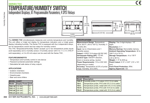
FEATURES/BENEFITS • Temperature and humidity control in one device • Password protected parameter settings • Selectable fail safe status of relay outputs
ACCESSORIES Model Description THC-P Humidity probe, 3 V output, 4 ft (1.2 m) cable TS-5 Temperature probe, PVC with 5 ft (1.5 m) cable TS-6 Temperature probe, metal with 5 ft (1.5 m) cable TS-51 Temperature probe, PVC with 10 ft (3 m) cable TS-61 Temperature probe, metal with 10 ft (3 m) cable
232 DWYER INSTRUMENTS, INC. |
SEDITY SWITCH
Independent Displays, 61 Programmable Parameters, 4 SPST Relays
Humidity Switches
4-3/32 [103.98]
2-7/16 1-15/16 [61.84] [49.21]
5-9/32 [134.30]
5 [127.00]
3-7/8 [98.43]
The SERIES THC simultaneously measures and controls temperature and humidity. The unit offers a 3-digit red display for temperature indication and a 3-digit green display indicating humidity. The Series THC is equipped with four independent relays, two for temperature control and two relays for humidity control. The THC Temperature/Humidity Switch accepts up to two temperature probe inputs (sold separately) and a humidity sensor. A humidity sensor with 0 to 1 V, 3 V (THC-P sold separately), or 4 to 20 mA output can be used with the Series THC.
温湿度控制器 说明书 V3.5
温湿度控制器使用说明书V3.5一.用途温湿度变送器的传感器采用进口产品,探 测范围宽,可对-40℃~120℃及 0~100%RH 范围之内的温湿度进行精确测量,电路使用温 度补偿,产品工作稳定可靠。
l 2 行 16 字符液晶显示温湿度,报警状态显示 l薄膜按键报警点修改功能l继电器输出l探头具有防结露功能l响应时间快l多种安装形式可选:一体壁挂式、管道安装和 分体壁挂式,可选配安装螺纹或法兰l探头外加专业的过滤器,大大提高使用寿命二.技术参数供 电:DC 24V(22V~26V) □量 程:湿度: 0%RH~100%RH温度:40℃~120℃(具体量程见产品标签)准 确 度: 湿度±3%RH (5%RH~95%RH,25℃) 温度±0.5℃(20℃~60℃)电路工作温度:20℃~60℃探头工作温度:40℃~120℃长期稳定性:湿度:﹤1%RH/y温度﹤0.1℃/y响应时间:湿度:﹤4s(1m/s 风速)温度﹤15s(1m/s 风速)输出信号:继电器输出(温度高,低报警;湿度高, 低报警)负载能力:AC 220V/5A,120V/10A安装方式:壁挂式:固定墙面分体式:法兰或螺纹安装管道式:法兰或螺纹安装外 壳:ABS 白色 90mm x 115mm x 55mm产品重量:壁挂型 约 440 克 管道型 约 580 克 三.外形、接线外形尺寸:90mm x 115mm x 55mm 1. 壁挂式2.分体式3.管道式Temperature & Humidity TransmitterTemperature & Humidity Transmitter温湿度控制器使用说明书V3.5接线说明:(任何错误接线均有可能对变送器造成 不可逆损坏)+24V:红色(电源+) GND: 黑色(电源-) 继电器输出:用户可根据下图任意接常开/常闭触 点。
温湿度控制器说明书
温湿度控制器说明书1. 产品概述1.1 功能特点- 温湿度监测:能够实时监测环境的温度和湿度。
- 控制功能:根据设定值自动调节空气条件,以达到所需的目标温湿度。
- 报警系统:当环境超出预设范围时发出声音或光信号报警。
2. 安装与设置2.1 硬件安装步骤:a) 将控制器插入电源插座,并确保供电正常;b) 连接传感器并放置在需要检测的位置上;c) 根据用户手册连接其他外部设备(如加热、降低湿度等)。
2.2 软件设置步骤:a) 打开控制面板,在菜单中选择“设置”选项;b) 输入所需的目标温湿度数值,并保存更改;c) 配置报警参数,包括触发阈值和响应方式。
3.使用方法及操作指南3.1显示屏介绍:a)当前室内/室外温湖显示区域;b)工作模式显示区域;c ) 设置按钮:用于进入设置界面进行参数调整;d)报警指示灯:当温湿度超出设定范围时,会有声音或光信号提示。
3.2操作步骤:a) 打开电源,并确保控制器正常启动;b) 根据需要,在显示屏上选择所需的工作模式(如自动、手动等);c ) 如果需要更改目标温湿度值,请按下“设置”按钮并根据菜单操作说明进行修改;d)观察当前环境数据和报警状态,必要时采取相应的行动。
4. 故障排除4.1 常见问题及解决方法:a) 控制器无法启动:检查电源连接是否正确。
b) 温湿度不准确:确认传感器位置是否合适,并重新校准系统。
c) 报警功能失效:检查配置文件中的阈值和响应方式。
5. 安全注意事项- 在使用过程中请遵循相关安全规定以及本产品用户手册提供的建议。
6.附件7.法律名词及注释:- 目标温湿度数值(Target Temperature and Humidity Value): 用户希望达到室内/室外空间里特定时间段内期待得到稳态条件下最佳的温度和湿度数值。
- 传感器(Sensor): 能够测量环境中特定物理量(如温度、湿度等)并将其转换为电信号输出的装置。
温湿度控制仪操作规程
温湿度控制仪操作规程温湿度控制仪是用于监测和调控环境中的温度和湿度的设备。
它广泛应用于工业、农业、医疗等领域,可以帮助维持合适的温湿度水平,保护设备和物品的质量。
为了正确使用温湿度控制仪,下面是一份操作规程,详细介绍了使用和维护温湿度控制仪的步骤和注意事项。
一、开机准备1. 确保温湿度控制仪已连接到电源,并且电源线完好无损。
2. 检查温湿度控制仪的传感器是否已正确安装并连接。
3. 检查温湿度控制仪的控制面板是否工作正常,无任何损坏或故障。
二、设置温湿度参数1. 打开温湿度控制仪的电源,等待其启动。
2. 进入温湿度控制仪的菜单界面,选择“设置温度”或“设置湿度”。
3. 根据实际需要,使用菜单界面上的调节按钮,逐步增加或减少温度和湿度设定值。
4. 确认设定值后,保存并退出菜单界面。
三、监测环境温湿度1. 温湿度控制仪会自动开始监测环境中的温度和湿度。
2. 在控制面板上,可以实时查看当前的温度和湿度数值。
3. 根据设定值和实际数值的比较,温湿度控制仪会开始调节环境中的温湿度。
四、维护和保养1. 定期清洁温湿度控制仪的控制面板和外壳,使用干净的布擦拭。
2. 检查温湿度控制仪的传感器是否干净和正常运作,及时清洁或更换损坏的传感器。
3. 定期校准温湿度控制仪,确保其测量的温湿度数值准确可靠。
4. 避免温湿度控制仪长时间处于高温、低温或潮湿环境中,以免损坏设备。
五、注意事项1. 在操作温湿度控制仪之前,务必先阅读并理解操作手册中的相关说明。
2. 避免温湿度控制仪接触水分或其他液体,以免损坏设备。
3. 在使用温湿度控制仪时,注意避免其受到撞击或摔落,以防损坏设备。
4. 如果发现温湿度控制仪发生故障或异常,应立即停止使用,并及时联系售后服务人员进行维修或更换。
5. 在操作温湿度控制仪期间,注意保持良好的工作环境,避免灰尘、恶劣气候等因素对设备的影响。
通过按照以上操作规程正确使用和维护温湿度控制仪,可以更好地保护设备和物品的质量,提高工作效率,减少因温湿度问题而引起的损失。
上海域信测控技术 THC-01型温湿度控制器 说明书
THC-01型温湿度控制器使用说明书一、 概述该控制器采用进口数字式温湿度一体化传感器,精度高,长期稳定性好,一路温度监控,一路湿度监控,根据环境温度的变化自动控制负载,调节温度及湿度至正常值,具有升温、降温、除湿、加湿等功能。
适用于电力高低压开关柜、箱式变电站,高等级恒温室(箱),蔬菜大棚、暖通空调、制冷、制药、烟草、化工、仓储等场所的温湿度控制。
二、技术参数 型号 THC-01 电源电压 220VAC/50Hz 电力消耗 约2W 控制输出 3A/250VAC 显示 LED 显示测量范围 温度:-40℃~+85℃;湿度:0-100%RH 分辨率 温度:0.1℃;湿度:1%RH 精度 温度:±0.5℃,湿度:±3.5%RH 温度设定范围 上限:0-99℃;下限:0-99℃湿度设定范围 上限:0-99%RH ;下限:0-99%RH 温度回差设定 上限回差:0-19℃;下限回差:0-19℃ 湿度回差设定 上限回差:0-19%RH ;下限回差:0-19%RH通讯 RS485接口,MODBUS-RTU 协议,波特率9600bps,地址可设定 环境温度 -10~70℃ 环境湿度 -5~95% 不结露 机械寿命 >3000,000次 重量 约210克,尺寸外形尺寸:96mm*96mm*130mm ;开孔尺寸:90mm*90mm三、外形图及端子定义 1.外形结构尺寸图如下侧视图正视图开孔尺寸2.后面板端子示意图1243568715161413111210917182019212624252322湿度上限湿度下限温度下限温度上限A B RS485VCC SCLK 传感器AC1AC2AC 220VGND DATA3.端子定义端子号 名称 描述1 J1K温度上限继电器输出 常开触点 2 J1COM 温度上限继电器输出 公共端 3 J2K 温度下限继电器输出 常开触点 4 J2COM 温度下限继电器输出 公共端 5 J3K 湿度上限继电器输出 常开触点 6 J3COM 湿度上限继电器输出 公共端 7 J4K 湿度下限继电器输出 常开触点 8 J4COM 湿度下限继电器输出 公共端 9 A RS485接口信号正极 10 B RS485接口信号负极 11 VCC 传感器供电电源正极 12 GND 传感器供电电源负极 13 SCLK 传感器数据线SCLK 14 DATA 传感器数据线DATA 15 AC1 16 AC2 供电电源 220VAC 17~26悬空四、前面板数据显示及操作说明 1. 两行LED 显示测量状态下:第一行显示实时温度,3位数据位外加符号位 00.0-99.9℃第二行显示实时湿度,2位数据位 00-99%RH参数查看或修改状态下:第一行显示参数序号F00—F10,共11个参数,序号对应参数含义如表1 第二行显示对应序号参数的数值,其范围和默认值如表1表1 序号 参数含义 范围默认值序号 参数含义 范围 默认值 F00 温度上限 00-99 50 F07 湿度上限回差 00-19 02 F01 温度下限 00-99 05 F08 通讯地址 01-99 01 F02 湿度上限 00-99 90 F09 保留 06 F03 湿度下限 00-99 20 F10 退出菜单 F04 温度上限回差 00-19 01 F05 温度下限回差 00-19 01 F06湿度上限回差00-19 022. 三个按键“↑”、“→”、“ENT ”分别表示“上移”、“右移”、“确认”可完成参数的显示选择与设定。
- 1、下载文档前请自行甄别文档内容的完整性,平台不提供额外的编辑、内容补充、找答案等附加服务。
- 2、"仅部分预览"的文档,不可在线预览部分如存在完整性等问题,可反馈申请退款(可完整预览的文档不适用该条件!)。
- 3、如文档侵犯您的权益,请联系客服反馈,我们会尽快为您处理(人工客服工作时间:9:00-18:30)。
THC305温湿度控制器设定说明
①通电,按设定“SET”键,表头显示,按“▲”或“▼”表头显示,此时为取消温度控制继电器的输出,只显示温度值。
②再按“SET”键,显示,按“▲”或“▼”显示,此时为取消湿度控制继电器的输出,只显示湿度值。
③再按“SET”键,显示,按“▲”或“▼”进行控制温度值的设定,可设定范围是01~98℃。
④再按“SET”键,显示,按“▲”或“▼”进行温度回差值的设定,设定范围01~15℃。
如按③④二项的显示设定,则为温度到达60℃时,温度控制继电器输出停止,“控温”红色指示灯灭;当温度降到55℃时,温度控制继电器输出接通,“控温”红色指示灯亮,加热装置动作。
⑤再按“SET”键,显示,按“▲”或“▼”进行控制湿度值的设定,可设定范围是10~95%。
⑥再按“SET”键,显示,按“▲”或“▼”进行湿度回差值的设定,设定范围01~30%。
如按⑤⑥二项的显示设定,则为湿度到达75%时,湿度控制继电器输出停止,“控湿”绿色指示灯灭;当湿度降到65%时,湿度控制继电器输出接通,“控湿”绿色指示灯亮,加湿装置动作。
⑦再按“SET”键,显示,按“▲”或“▼”进行湿度零点修正,设定值为080~120,对应的湿度修正范围约为0~20%。
无控制输出指示灯灭,有控制输出指示灯亮。