三相标准程控电源说明书
JWT系列三相交流工业电源说明书
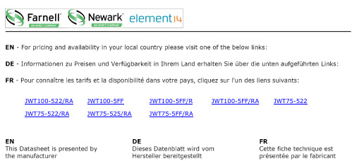
JWT100-522/RA JWT100-5FF JWT100-5FF/R JWT100-5FF/RA JWT75-522 JWT75-522/RA JWT75-525/RA JWT75-5FF/RAJWT Series1JWT SeriesTriple OutputIndustrial Power SuppliesKey Market Segments & ApplicationsFactory Automation:Process Control, NC-Machining,Automotive, Packaging Equipment,Materials Handling,Chemical Processing, Robots Test & Measurement:Burn-in & Test,Automated Test, Instrumentation,Measurement, Detection•5 Year Warranty•Power Factor Corrected•Approved to VDE01 60 Machinery Directive •Universal Input (85 265VAC)JWT Features and BenefitsFeaturesBenefits• VDE01 60 Approved • No Additional Approvals Needed • 5 Year Warranty• Lower Cost of Ownership • Power Factor Corrected • Supports Global Use• Level B EMI• Assists Systems ComplianceSpecificationsMODELJWT75JWT100ITEMSMax Output Power W 75100Efficiency (Typ)%72Input Voltage range -85 - 265VAC (47 - 63Hz) or 120 - 330VDCInput Current Typ A 1.2 / 0.6 1.4 / 0.7Inrush Current A 14A at 100VAC, 28A at 200VAC inputPower Factor-Meets EN61000-3-2Output Voltage Accuracy -V1 variable, V2 & V3 +/-5%Temperature Coefficient -V1 & V2 <0.02%/ºC, V3 <0.03%/ºCOvercurrent Protection ->105%Overvoltage Protection V Main output only: 5.7 - 7VHold Up Time (Typ)ms 20Leakage Current-0.75mA Max, 0.44mA typical at 230VACOperating Temperature --10ºC to +65ºC, derate linearly to 50% load from 50ºC to 65ºC -10ºC to +50ºC, derate linearly to 60% load from 40ºC to 50ºC with coverStorage Temperature ºC -30 to +85Humidity -30 - 90% RH (operating), 10 - 95% RH (non operating)Cooling-ConvectionWithstand Voltage -Input to Ground 2kVAC (20mA), Input to Output 3kVAC (20mA),Output to Ground 500VAC (100mA) for 1 min.Isolation Resistance ->100M at 25ºC & 70%RH, Output to Ground 500VDC Vibration (non operating)-10 - 55Hz (1 minute sweep), 196m/s 2constant X, Y, Z 1 hourShock-<196.1m/s 2Safety Agency Approvals -IEC/UL/CSA/EN62368-1, 60950-1, CE Mark Conducted & Radiated EMI -EN55011 / EN55022-B, FCC Class B, VCCI-B Weight (Typ)g 600720Size (WxHxD)mm 42 x 92 x 18848 x 92 x 203Warranty- 5 YearsNote:See Installation Manual for full details, test methods of parameters and application notes.2JWT SeriesModel SelectorOptionsSuffix DescriptionBlank Screw terminals, no cover/A Screw terminals, cover (Standard US stock item)/RRemote On / Off ExampleJWT75-525/RCAdjust. Min Max Load Reg Line Reg Ripple & Model Output Voltage Range Current (A)Current (A)(mV)(mV)Noise (mV)JWT75-522/AV1+5V 5 - 5.250.884020120V2+12V -0410048150V3-12V -00.515048150JWT75-5FF/AV1+5V 5 - 5.250.884020120V2+15V -0 3.212060150V3-15V -00.515060150JWT75-525/AV1+5V 5 - 5.250.884020120V2+12V -0410048150V3-5V -00.510020150JWT100-522/AV1+5V 5 - 5.25 1.3134020120V2+12V -0 5.510048150V3-12V -0115048150JWT100-5FF/AV1+5V 5 - 5.25 1.3134020120V2+15V -0 4.512060150V3-15V -0115060150JWT100-525/AV1+5V 5 - 5.25 1.3134020120V2+12V -0 5.510048150V3-5V-0110020150Outline Drawing JWT SeriesF R O N T V I E WS I D E V I E WHHWDW(B O T H S I D E S )M O U N T I N G S U R F A C ETDK-Lambda France SASTDK-Lambda AmericasTDK Electronics do Brasil LtdaTel:+33 1 60 12 71 65*****************************/frTel: +55 11 3289-9599****************************.com /enTel: +1 800-LAMBDA-4 or 1-800-526-2324**************************Italy Sales OfficeTel:+39 02 61 29 38 63*****************************/itNetherlands*****************************/nlTDK-Lambda Germany GmbHTel:+49 7841 666 0**************************/deAustria Sales OfficeTel:+43 2256 655 84*****************************/atSwitzerland Sales OfficeTel:+41 44 850 53 53*****************************/chNordic Sales OfficeTel:+45 8853 8086*****************************/dkTDK-Lambda UK Ltd.Tel:+44 (0) 12 71 85 66 66**************************/ukTDK-Lambda Ltd.Tel:+9 723 902 4333**************************/il-enTDK-Lambda CorporationTel: +TDK-Lambda Singapore Pte Ltd.Tel: +65 6251 7211*********************TDK-Lambda (China) Electronics Co. Ltd.Tel: +86 21 6485-0777**************************TDK India Private Limited, Power Supply DivisionTel: +91 80 4039-0660*********************For Additional Information, please visit https:///en/power/JWT SeriesJWT Mar21 v43JWT100-522/RA JWT100-5FF JWT100-5FF/R JWT100-5FF/RA JWT75-522 JWT75-522/RA JWT75-525/RA JWT75-5FF/RA。
三相交流电源TFC63系列操作手册V1.0说明书

Three Phase AC SourceTFC63 Series Operation Manual V1.0SAFEFY INSTRUCTION................................................................................................................................... - 2 -1. KEY POINTS TO INSTALLATION ............................................................................................................ - 3 -1.1 Unpacking and Examination ................................................................................................................ - 3 -1.2 Preparation before Use.......................................................................................................................... - 3 -1.3 Storage and Shipping ............................................................................................................................ - 4 -2. SPECIFICATOINS ......................................................................................................................................... - 5 -2.1 Serial Lineup and Features................................................................................................................... - 5 -2.2 Specifications.......................................................................................................................................... - 6 -2.3 Block Diagram ....................................................................................................................................... - 7 -3. OPERATION INSTRUCTIONS.................................................................................................................... - 8 -3.1 Front Panel Description ........................................................................................................................ - 8 -3.2 Operation Instructions .......................................................................................................................... - 9 -3.2.1 Power On ................................................................................................................................... - 9 -3.2.2 Setting Mode .............................................................................................................................. - 9 -3.2.3 Output Mode ............................................................................................................................ - 10 -3.2.4 Error Mode ............................................................................................................................... - 10 -3.3 Operation Instructions to Buttons...................................................................................................... - 11 -4. FAULTS AND TROUBLE SHOOTING..................................................................................................... - 12 -5. MAITENANCE ............................................................................................................................................. - 13 -5.1 Inspection ............................................................................................................................................. - 13 -5.2 Cleaning................................................................................................................................................ - 13 -5.3 Modification ......................................................................................................................................... - 13 -Use of Operation ManualPlease read through and understand this Operation Manual before operating the product. After reading, always keep the manual nearby so that you may refer to it as needed. When mobbing the product to another location, be sure to bring the manual as well.Calibration notificationWe notify that the instruments included in this manual are in compliance with the features and specifications as stated in this manual. Before shipment, the instrument has been calibrated in factory. The calibration procedures and standards are compliant to the national regulations and standards for electronic calibration.WarrantyWe guarantee that the instrument has been passed strict quality check. We warrant our instrument’s mainframe and accessories in materials within the warranty period of one year. We guarantee the free replacement or repair of products which are approved defective. To get repair service, please contact with your nearest sales and service office. We do not provide any other warranty items except the one being provided by this summary and the warranty statement. The warranty items include but not being subjected to the hinted guarantee items related to tradable characteristics and any particular purpose. We will not take any responsibility in cases regarding to indirect, particular and ensuing damage, such as modifications to the circuit and functions by the users, repairing or component replacement by the users, or damage during transportation.For product improvement, the specifications are subject to change without prior notice.SAFEFY INSTRUCTIONThis chapter contains important safety instructions that you must follow when operating the AC power supply and when keeping it in storage. Read the following before any operation to insure your safety and to keep the best condition for the instrument.Safety SymbolsThe following safety symbols may appear in this manual or on the instrument:WARNINGIdentifies conditions or practices that could result in injury or loss oflife.CAUTIONIdentifies conditions or practices that could result in damage to theinstrument or to other properties. DANGERHigh voltageATTENTION Refer to the manual Protective conductor terminalOperation instructionSafety GuidelinesCAUTION●Before plugging into local AC mains, check and make sure that the output voltage is compatible to the load. (It is suggested to disconnect a load before plugging into local AC mains. ● Do not use this instrument near water.● Do not operate or touch this instrument with wet hands.● Do not open the casing of the instrument when it is connected to ACmains.● Avoid touch the metal contact part of the output terminals.● Do not use the instrument in an atmosphere which contains sulfuric acidmist or other substances which cause corrosion to metal.● Do not use the instrument in a dusty place or a highly humid place assuch will cause instrument reliability degradation and instrument failures.● Install the instrument in a place where is free from vibration.● Install the instrument in a place where the ambient temperature is inrange of -20~60℃. Note that the instrument operation may become unstable if it is operated in an ambient temperature exceeding the range of 0~40℃Power supplyWARNING AC Input voltage: 220V (single phase) /380V (three phase) ±10%, 50/60Hz Connect the protective grounding conductor of the AC power cord to an earth ground to avoid electrical shock.FuseWARNING● Make sure the correct type of fuse is installed before power up.● Replace the AC fuse with the same type and rating as the original fuse. ● Disconnect the power cord before fuse replacement.● Make sure the cause of fuse blowout is fixed before fuse replacement.1. KEY POINTS TO INSTALLATIONThis chapter introduces the rules of product unpacking, examination, preparation of pre-use and storage.1.1 Unpacking and Examination1. Unpack the AC power supply and check the enclosed accessories. During unpacking, DO NOTmake the power supply cabinet slope for more than 45 degrees.2. The product is sealed in a packing case which is protected by EPE foarm. If there are any damages with the packing case, please check the AC power supply and see if there is any deformation, scratch or panel damaged.3. In case of any damage, please inform us or local distributor immediately. Our service center will maintain it or replace it with a new one. However, please do not return it without a notification to us or local distributor.Packing list:AC power supply: 1 unit Operation manual: 1 pcs RS232 cable: 1pcs (optional) RS485cable: 1pcs (optional)1.2 Preparation before UseInput PowerThe input power requirements of the instrument are 220V±10% (50Hz±10%) single phase AC or 380V±10% (50Hz±10%) three phase AC. Please use a proper input power before turn on the AC power supply, and use a fuse with same specification of the original. The fuse specification is indicated on the rear panel of the power supply.WARNINGDisconnect the power cord before fuse replacement.WARNINGAlways keep good connection of the grounding wire and make sure to connect the grounding wire to the earth. The 3-pin power plug of the power supply must be connected to a socket with grounding wire. To use a longer wire, make sure it is perfectly grounded to the earth. When the 3-pin power plug of the power supply is plugged into a socket with grounding wire, the power supply has been grounded to the earth.Operation EnvironmentLocation: The installation sites must be away from chemical deposition, explosive material, sulfuric acid mist or other substances which cause corrosion to metal. The installation site shall always keep lean and dry, and free from dusty, high humidity and vibration. Relative Humidity: < 80% Altitude: < 2000m Temperature: 0℃ to 40℃1.3 Storage and ShippingEnvironmentLocation: The storage sites and transportation environment must be away from chemical deposition, explosive material, sulfuric acid mist or other substances which cause corrosion to metal. The installation site shall always keep lean and dry, and free from dusty, high humidity and vibration. Relative Humidity: < 80%Altitude: <7620mTemperature: -20℃ to 55℃The power supply must avoid extreme temperature change, because drastic temperature change will cause vapor condensation inside the power supply.Packing●Original PackingPlease keep all the original packing materials and pack the power supply if it must be sent back to us for repairing. And contact our service center before returning. All the accessories included with the power supply must be returned along with the power supply, and demonstrate the damage or malfunction. In addition, please mark the package with a label indicating FRAGILE AND HANDLE WITH CARE.●Other PackingIf the original packing materials are not found, please follow the following instructions to pack the power supply:1.Pack the power supply with bubble plastic bag or EPE foarm.2.Put it into a multi-layer carton which can withstand a weight of 150kg.e shockproof materials to filled around the power supply with thickness of 70~100mm.4.Seal the carton properly.5.Marked the carton with a label indicating FRAGILE AND HANDLE WITH CARE.2. SPECIFICATOINS2.1 Serial Lineup and FeaturesMain FeaturesPerformance Adopts RF SPWM regulation technology, fast response speed, good stability High power MOS/IGBT drive, reliable operation, strong over load capacityOperation Full range adjustable output: 0~150V, 0~300V, step 0.1VOutput frequency: 50Hz, 60Hz, 47-63Hz, 100Hz, 200Hz, optional 400HzFast output key for 220V/50Hz, 110V/60Hz and 120V/60HzTiming function, for output control 0~16 hoursHigh accuracy LED display for voltage, current, frequency, active power,power factorFast transient response, response time no more than 2ms for 100% load and unloadProtection Over voltage, over current, over load, and over temperature protectionsInterface RS232 (optional)RS485 (optional)Applications Automotive test systemBest power source for R&DElectronic/electrical products testSwitching power supply and transformer testCompressor and motor testMonitor testAir-conditioning equipments testFluorescent rectifier testFactory use for QC, life test, etc.400Hz switching power supply for military, airport and navigation systems, supercomputer, etc.2.2 SpecificationsGeneral specificationsCircuit mode IGBT/PWMInput 1φ2W, 220V±10% or 3φ4W, 380V±10%, 50±5Hz OutputPhase 3 phase, Phase difference: 120°±2°Low range Phase voltage 0V-150V, Line voltage 0-260V High range Phase voltage 0V-300V, Line voltage0-520VFrequencyAdjustable output: 47-63Hz, optional 45-400Hz Fixed output: 50Hz, 60Hz, 100Hz, 200Hz, optional 400HzFrequency accuracy ≤0.01%Line regulation ≤1%Load regulation ≤1%Harmonic distortion ≤2% (tested with resistive load)Efficiency ≥80%Response time Max.2msMeter & ResolutionFrequency meter 4 digits LED, resolution 0.1HzVoltmeter 4 digits LED, resolution 0.1VAmmeter 4 digits LED, resolution 0.1A/0.01APower meter 4 digits LED, resolution 0.1kW /0.001kWPreset function Preset output voltage, output frequency and output voltage floating ratio Hot key function Hot key for frequency switch, output voltage floating selectionAlarm function Audible and visual alarm once protective device activated; display errorcode on LEDProtectionFuse switch for input and output;Fast-response circuit to detect over voltage, over current, over load, over temperature and short circuit; Output will be shut down in protectionmode.Cooling Forced ventilation Cabinet protection grade IP2XOperation environmentTemperature: 0℃-45℃Humidity : 0-90% (Non-condensing) Altitude : 1500 feetOutput specifications (3 phase input)Model 6303 6306 6310 6315 6320 6330 Total outputcapacity3KVA 6KVA 10KVA 15KVA 20KVA 30KVAOutput capacity perphase1KVA 2KVA 3.3KVA 5KVA 7KVA 10KVAMax. current 1.0V-150V 8.4A 16.8A 28A 42A 58A 84A 150.1V-300V 4.2A 8.4A 14A 21A 29A 42AOutput specifications (3 phase input)Model 6345 6360 63100 63150 63300 63450 Total outputcapacity45KVA 60KVA 100KVA 150KVA 300KVA 450KVAOutput capacity perphase15KVA 20KVA 33KVA 50KVA 100KVA 150KVAMax. current 1.0V-150V 126A 168A 276A 416A 834A 1260A 150.1V-300V 63A 84A 138A 208A 417A 630A2.3 Block Diagram3. OPERATION INSTRUCTIONS 3.1 Front Panel Description1 2 3 4 5 6 7 10 11 12 13 814 9 15 16 17 18 19Fig 3.1 Front panel1 Voltage meter for phase A: displays setting voltage and output voltage2 Voltage meter for phase B: displays setting voltage and output voltage3 Voltage meter for phase C: displays setting voltage and output voltage4 Current/Watt meter for phase A: displays output current/active power5 Current/Watt meter for phase B: displays output current/active power6 Current/Watt meter for phase C: displays output current/active power7 Current/Watt indicator: when the “A” indicator lights on, the meter displays output current and its unit is “A”. When the “kW” indicator lights on, the meter displays active power and its unit is “kW”. When both indicators light off, the meter display power factor. 8 Frequency meter: display setting frequency and output frequency.9 Start indicator: lights on to indicate that the power source is already started. 10 Upper float key 11 Lower float key 12 Switch key13 Hot key for output frequency switch between 50Hz and 60Hz 14 Parameter setup key15 Start key: press to start the power source 16 “+” key: press to increase parameter 17 “-” key: press to decrease parameter 18 Stop key: press to stop output19 Current/Watt key: press to switch display between current, active power and power factor3.2 Operation InstructionsWARNING ●Before connecting to local AC mains check and make sure to usecorrect AC power to the power supply.●Connect the protective grounding conductor of the AC power cord to anearth ground to avoid electrical shock.●Switch off all switches.●Ensure 200mm space for front and back sides of the AC power sourcefor purpose of good ventilation.●Do not use the AC power source when there is thundery weather.3.2.1 Power OnPress the power button to turn on the power supply. There will be 10 seconds of soft start delay before the AC power source enters standby status (refer to below for standby status)Standby modeNOTE: All buttons has no response to operation during soft start.3.2.2 Setting ModePress SET button to go into setting mode. Press + or - button to increase or decrease parameters of frequency, voltage, upper or lower float. After parameter setup is finished, press Stop button to return to standby mode.Setting mode3.2.3 Output ModeIn standby mode, press Start button to start output. The LED displays output voltage, load current and watt. Press Current/Watt button to switch meter display between current, active power and power factor.Output mode, display current of all 3 phasesOutput mode, display active power of all 3 phasesWARNING Even if the output and input of the AC power source are isolated, dangerousvoltage on the output terminals remain as a jeopardize to operator of thisunit. Press Stop button to stop output and get back to standby mode.3.2.4 Error ModeWhen there is error to the AC power source, there will be audible and visual alarm, and the unit will go into error mode. The LED will display error code. Press Stop button to stop alarm and get back to standby mode.Error mode3.3 Operation Instructions to ButtonsButton Operation instructionsStop a)To stop output in output mode.b)To stop alarm.c)To exit parameter setup in setting mode.Start In standby mode, press to start output.SET a)Press once to go into frequency setup.b)Make a 2nd press to go into voltage setup.c)Make a 3rd press to go into voltage upper float setup (setting range5%~20%).d)Make a 4th press to go into voltage lower float setup (setting range-5%~-20%).e)Make a 5th press to exit setting mode and store all settings.Press this key once again to recycle the above operations.+ a)In output mode, press this button to increase output voltage.b)In setting mode, press this button to increase setting parameter.- a)In output mode, press this button to decrease output voltage.b)In setting mode, press this button to increase setting parameter.Upper float In output mode, press this button to increase output voltage. Lower float In output mode, press this button to decrease output voltage.50Hz/60Hz/400Hz A key shortcut to switch between 50Hz, 60Hz and 400Hz output in output mode or in setting mode.Current/Watt In output mode, press to switch between display of current, active power and power factor.4. FAULTS AND TROUBLE SHOOTINGFault Power switch indicator dose not light on after connected to local AC mains.Causes 1.The input power plug is not properly connected.2.The fuse is blown.Clear 1.Check if the power plug is properly connected.2.Disconnect from local AC mains and replace fuse with same specificationFault Error code displayed on LED.Causes There is big impact loads connected to the grid, for example, welding machine, controlled rectifier device. It can be caused by thunder.Clear Turn off the AC power source and restart it.Fault There is alarm and LED displays 000X.Causes Find out the cause according to error code.0001: Short circuit protection.0002: Over temperature protection.0003: Over current protection.Clear Clear error according to error code, and restart the AC power source. If it is caused by over temperature protection, restart the unit after 5 minutes.If the faults cannot be cleared, please notify our service center or local distributor.5. MAITENANCE5.1 Inspection●Inspect the power supply at regular intervals so that it maintains its initial performance for along time.●Check the input power cord for damage of the vinyl cover and overheating of the plug and cordstopper. Check the terminal screws and binding posts for loosening.●Remove dust from the inside of the casing and ventilation holes of the cover by using acompressed air of the exhaust air of a vacuum cleaner.●If the power supply has not been used for a long time, please power on the power supply towarm up for two hours every three months.5.2 Cleaning●Before cleaning, disconnect the AC mains.●To clean the power supply, use a soft cloth dampened in a solution of mild detergent and water.Do not spray cleaner directly onto the power supply, since it may leak into the cabinet and cause damage.●Do not use chemicals containing benzene, benzene, toluene, xylene, acetone, or similarsolvents.●Do not use abrasive cleaners on any portion of the power supply.5.3 ModificationNo any modifications to the circuit or the components can be made to the power supply by the users. In case of any modifications by the users, the warranty will automatically expire with the power supply. And we do not take any responsibility hereafter incurred. If the returned unit be found with any modifications, we will make the power supply to the original status and charge for maintenance service.。
eTM-300W程控电源

DC power supply直流稳压电源程控电源系列产品使用说明书目录安全概要----------------------- 1第一章概述--------------------- 3第二章操作说明---------------- 11第三章维护-------------------- 15第四章性能指标--------------- 17第五章产品有毒有害物质申明...., (19)第六章保修服务---------------- 20保修卡________________________ 22性能指标若有变动恕不另作声明。
安全概要这章节包含了操作电源和储藏环境必须遵循的重要安全说明,为确保您的人身安全,请在操作之前熟读以下操作说明,确保电源供应器在最佳的工作环境。
安全指南-------------------------------------------・不要放置重物在机壳上。
・避免严重撞击或不当的处置导致机器损・注一坏。
连接仪器时需采取预防静电放电的措施。
不要阻挡或隔离风扇通风口。
除非是专业人员,请勿打开机器。
电源供应・・AC 输入电压:220V±10%' 50Hz (110V 输入或100V/220V手动切换)电源线的接地线需连接到接地端,以避免电击一般介绍保险丝•开机前确保使用正确的保险丝型号。
• 为防止火灾,要替换符合型号和额定值的保险丝。
•替换保险丝前先切断电源,排除造成保 险丝损坏的原因 清洁机器•清洁前先切断电源。
•使用温和的洗涤剂和清水沾湿柔软的 布,不要直接喷洒清洁剂。
• 不要使用化学或清洁剂含研磨的产品例加苯甲苯二甲苯和丙酮操作环境 • 使用地点:室内,避免直接日晒,灰尘以及强烈磁场的地方。
•相对湿度:<80% •海拔:<2000m •温度:5℃到40℃ 存储环境 •位置:室内 • 相对湿度:<60%_•——温度:5r 到30r ------------------------第一章概述本系列产品是一款单输出的程控直流稳 压电源,LED 数字显示,可同时显示电压、电流和功率。
三相程控精密测试电源
三相程控精密测试电源三相程控精密测试电源二、简介HT3050三相程控精密测试电源是基于1.2G MAC的DSP、大规模的FPGA、高速高精度的DA以及高保真功率放大器构成的新一代高精度标准功率源。
适用于电力系统的电测、热工、远动、调度等需要测量、检验及高精度标准信号源的电力部门和企业,也适用于其它需要高精度标准信号源进行测量、检验的场合。
HT3050可以输出工频(40Hz~65Hz)频率、相位及幅度可调的高精度电压电流,是非常高精度的可调电压电流标准源。
HT3050可以输出非常纯净的正弦电压电流,其失真度不超过0.1%。
HT3050的电压电流输出有着非常高的输出稳定度,典型值为0.03%RD。
因此其非常适合用于需要高精度检验校准的工作场合,比如计量部门对于各种电压、电流、功率等电参数表计的检测。
三、主要特点1、可以输出纯净的,失真度在0.1%(典型值)的正弦功率信号。
2、可以在基波上叠加各次谐波输出。
3、频率输出从40Hz~65Hz任意可调,分辨率0.005Hz,准确度0.005Hz。
4、A、B相为一个频率基准,C相是一个单独的频率基准,因此可以分相变频。
5、相位0~360度任意可调,可以方便模拟各种供电情况,甚至反送电的情形。
6、强劲的带载能力,可以带容性、感性、阻性负载或者复合类型负载,且负载调整率优于0.03%RG。
7、极佳的温度稳定性,核心器件为温度系数小至1PPM的军工级产品,可以在室外的温度环境下保证输出的精度。
8、采用32位MCU+DSP处理器,功能强大灵活。
9、工频每周波高达50000点的波形捏合,内部信号输出无需滤波器进行平滑滤波,保证了波形的精确输出,使得系统可以输出精确的谐波,也使系统拥有极佳的谐波失真度指标。
10、可通过一个RS232方便和PC相连,拓展其他功能。
11、完善的过流、过压、过热、短路、开路、过载保护。
12、硬件PID,响应极快,负载的改变不会引起输出的丝毫波动。
HS-5320(0.05级)三相多功能标准表使用说明书

HS-5320 三相多功能标准表使用手册目录第一章产品概述 (3)第二章功能特点 (3)第三章技术简介 (4)3.1 信号范围 (4)3.2 准确度 (4)3.3 输入阻抗 (4)3.4 工作环境 (5)3.5 其它 (5)第四章工作原理 (5)第五章结构与接线 55.1 结构 (5)5.2 接线 (6)第六章操作方法 66.1 开机关机 (6)6.2 常规测量 (7)6.3 电能误差校验 (13)6.4 被检表脉冲常数测量 (18)6.5 电能累计 (19)6.6 相位测量 (20)6.7 谐波分析 (23)6.8 量程选择 (24)6.9 主菜单 (25)6.10 仪器参数设置 (26)6.11 数据管理 (30)第七章扩展功能 (36)第八章其它功能 (37)第九章附件 (38)第一章产品概述HS-5320三相多功能标准电能表是我公司开发的高精度多功能宽量程标准电能表。
其精度等级为0.05级。
重量轻,体积小,精度高,采用DSP、嵌入式技术,以及温度自动平衡技术和其他补偿技术,指标稳定,功能丰富,界面新颖,操作清晰简单,工作可靠。
可广泛应用于电能计量行业、电能实验室和其他相关部门,既可以在实验室使用,又能携带到现场工作。
注意:为确保您的工作顺利进行,更为确保您和您使用的设备的安全,请您在使用本产品前仔细阅读本说明书。
第二章功能特点1.采用标准便携铝机箱,体积更小(目前为国内同类产品体积最小355*145*185mm)重量更轻(7.5公斤),更加方便携带。
2. 宽量程测量:电压测量范围(相电压):1~560V。
电流测量范围: 10mA ~120A3. 多种方式测量:可在单相、三相四线Y/三线Δ等各种接线方式下对交流电压、电流、功率(有功功率、无功功率、视在功率)及电能进行4象限测量;其中无功功率及电能可进行真无功、夸相无功、人工中性点无功等多方式测量。
4. 多功能测量:a. 电压、电流、相位、频率、有功、无功、功率因素、误差等基本测量功能。
程控电源PWS4305说明书

HT3050三相程控精密测试电源
一、注意事项1电压输出不允许相间短路,否则将可能烧毁内部功率器件。
1) 尽管本设备带有过载和短路保护,但建议用户工作在额定功率值以下,以保证设备的长期稳定运行(电压输出不可短路,电流不可以开路)。
2) 本装置C相的频率单独可调,当C相的频率和A、B相不一致时,相位的测量便失去了意义。
3) 当装置异常发出声音告警时,应及时关断电源,以免降低装置的使用寿命。
4) 不可以用手接触设备的电压输出端以免触电。
5) 设备出现问题请及时通知我公司维修,没有经过专业培训的人员不可以拆开本设备。
6) 设备电源输入端只能使用5A/221V的标准保险丝。
7) 使用本设备时,请保证机壳可靠接地,以保证人身安全,设备背后有接地螺栓可以用于安全接地,或者保证三叉电源线的中线已经可靠接入大地回路。
警告:请在本说明书规定的条件下使用本设备,以保证设备和人员的安全。
二,简介HT3050程控测试电源是基于1.2G MAC的DSP、大规模的FPGA、高速高精度的DA以及高保真功率放大器构成的新一代高精度标准功率源。
适用于电力系统的电测、热工、远动、调度等需要测量、检验及高精度标准信号源的电力部门和企业,也适用于其它需要高精度标准信号源进行测量、检验的场合。
HT3050可以输出工频(40Hz~65Hz)频率、相位及幅度可调的高精度电压电流,是非常高精度的可调电压电流标准源。
HT3050可以输出非常纯净的正弦电压电流,其失真度不超过0.1%。
HT3050的电压电流输出有着非常高的输出稳定度,典型值为0.03%RD。
因此其非常适合用于需要高精度检验校准的工作场合,比如计量部门对于各种电压、电流、功率等电参数表计的检测。
三、主要特点1、可以输出纯净的,失真度在0.1%(典型值)的正弦功率信号。
2、可以在基波上叠加各次谐波输出。
3、频率输出从40Hz~65Hz任意可调,分辨率0.005Hz,准确度0.005Hz。
4、 A、B相为一个频率基准,C相是一个单独的频率基准,因此可以分相变频。
三相程控精密测试电源使用指南
三相程控精密测试电源三相程控精密测试电源使用指南1、接线使用HT3050前,首先要接上电源,HT3050供电电源为单相工频220V,通用于国内一般的市电。
背板上有电源插座,接上电源后打开电源开关,功率源开始上电工作,上电后功率源处于输出停止状态,操作界面停留在开机主界面上面。
然后可以进行负载接线操作,负载接线也可以在上电之前进行。
接线一定要在标准源输出停止的状态下进行,否则容易导致电压短路和电流开路等故障。
电压接线严禁对地短路。
电流在输出停止的状态下可以进行接线,而不用对标准源断电。
电压和电流输出可以有单点连接。
注意:电压输出不可短路,电流输出不可开路。
i.前面板产品的前面板示图如图1所示。
图1 产品前面板ii.接线端子说明名称含义备注Ua(黄) A相电压输出正端Ub(绿) B相电压输出正端 三相程控精密测试电源Uc(红)C 相电压输出正端 Un(黑)电压输出公共端 Ia(黄)A 相电流输出正端 Ia(黑)A 相电流输出负端 Ib(绿)B 相电流输出正端 Ib(黑)B 相电流输出负端 Ic(红)C 相电流输出正端 Ic(黑)C 相电流输出负端iii. 后面板 后面板根据不同的选配功能,其布置不一样标准的输入端子(1---5)第一脚(PIN1):信号(其他颜色)第二脚(PIN2):未用第三脚(PIN3): 5V 电源 未引出第四脚(PIN4):未用第五脚(PIN5):地(黑色)当配置为电能输入时: 相对常见的电能表脉冲输出方式,HT3050脉冲输入接线方法:5---地4---未用 2---未用 电源---3信号---1 三相程控精密测试电源D601IN4004R6014.7KR602430NC 1IN+2IN-3NC 4VCC 8VB 7Ou t 6Gn d 5U6016N139R60351K CGNDCVCC+5VN65VGND C6011nf R60410K CGND 电表M+M-+5V Sig n alGND当电表为无源脉冲时,合上时光隔关断,断开时光隔导通.当电表为有源脉冲时,高电平光隔导通,低电平时光隔关断电表的脉冲正端接 信号---1,负端接 5---地当配置为SOE 输入时用户必须提供无源的输入节点,或者5V 的湿节点。
- 1、下载文档前请自行甄别文档内容的完整性,平台不提供额外的编辑、内容补充、找答案等附加服务。
- 2、"仅部分预览"的文档,不可在线预览部分如存在完整性等问题,可反馈申请退款(可完整预览的文档不适用该条件!)。
- 3、如文档侵犯您的权益,请联系客服反馈,我们会尽快为您处理(人工客服工作时间:9:00-18:30)。
矿产资源开发利用方案编写内容要求及审查大纲
矿产资源开发利用方案编写内容要求及《矿产资源开发利用方案》审查大纲一、概述
㈠矿区位置、隶属关系和企业性质。
如为改扩建矿山, 应说明矿山现状、
特点及存在的主要问题。
㈡编制依据
(1简述项目前期工作进展情况及与有关方面对项目的意向性协议情况。
(2 列出开发利用方案编制所依据的主要基础性资料的名称。
如经储量管理部门认定的矿区地质勘探报告、选矿试验报告、加工利用试验报告、工程地质初评资料、矿区水文资料和供水资料等。
对改、扩建矿山应有生产实际资料, 如矿山总平面现状图、矿床开拓系统图、采场现状图和主要采选设备清单等。
二、矿产品需求现状和预测
㈠该矿产在国内需求情况和市场供应情况
1、矿产品现状及加工利用趋向。
2、国内近、远期的需求量及主要销向预测。
㈡产品价格分析
1、国内矿产品价格现状。
2、矿产品价格稳定性及变化趋势。
三、矿产资源概况
㈠矿区总体概况
1、矿区总体规划情况。
2、矿区矿产资源概况。
3、该设计与矿区总体开发的关系。
㈡该设计项目的资源概况
1、矿床地质及构造特征。
2、矿床开采技术条件及水文地质条件。