sfp+光模块使用手册
NETGEAR 1000Base-X SFP 光模块说明书

Installation Guide2. Grasp the sides of the module and pull it straight forward out of the slot.AGM731F and AGM732FThe 1000Base-X SFP transceiver module provides full-duplex 1000Mbps Ethernet operation in each direction for NETGEAR managed switches.The switch automatically detects the module, so you can simply plug it into an available module slot.StandardsAGM731F: IEEE 802.3z, 1000Base-SX AGM732F: IEEE 802.3z, 1000Base-LXConnectorsAGM731F: LC for 62.5/125µm or 50/125µm cable AGM732F: LC for 9/125µm cableDimensions (H x W x D)AGM731F: 2.23 x 0.53 x 0.34 in (56.8 x 13.6 x 8.6 mm)AGM732F: 2.26 x 0.53 x 0.33 in (57.4 x 13.4 x 8.5 mm)WeightAGM731F: 0.58 oz (16.3 g)AGM732F: 0.56 oz (16.0 g)Storage temperature –40–185ºF (–40–85ºC)Case operating temperature23–158ºF (–5–70ºC)Operative relative humidity85% at 77ºF (25ºC)Operating distance multi-mode fiber (MMF)AGM731F:OM1: 900 ft (275 m)OM2: 900–1,800 ft (275–550 m)OM3: 1,800 ft (550 m)Operating distance single mode fiber (SMF)AGM732F: 6 mi (10 km)Power consumption 1.1WMTBFAGM731F: >10 years AGM732F: >10 yearsSafety certification UL 60950-1, CSA-C22.2 No.60950-1Environmental complianceRoHSNETGEAR, Inc.350 East Plumeria Drive San Jose, CA 95134, USA NETGEAR INTERNATIONAL LTD Floor 1, Building 3University Technology Centre Curraheen Road, Cork,T12EF21, Ireland© NETGEAR, Inc., NETGEAR and the NETGEAR Logo are trademarks of NETGEAR, Inc. Any non‑NETGEAR trademarks are used for reference purposes only.Support and CommunityVisit /support to get your questions answered and access the latest downloads.You can also check out our NETGEAR Community for helpful advice at.Regulatory and LegalSi ce produit est vendu au Canada, vous pouvez accéder à ce document en français canadien à https:///support/download/.(If this product is sold in Canada, you can access this document in Canadian French at https:///support/download/.)For regulatory compliance information including the EU Declaration of Conformity, visit https:///about/regulatory/.See the regulatory compliance document before connecting the power supply.For NETGEAR’s Privacy Policy, visit https:///about/privacy-policy.By using this device, you are agreeing to NETGEAR’s Terms and Conditions athttps:///about/terms-and-conditions. If you do not agree, return the device to your place of purchase within your return period.Do not use this device outdoors.Applicable to 6 GHz devices only: Only use the device indoors. The operation of 6 GHz devices is prohibited on oil platforms, cars, trains, boats, and aircraft, except that operation of this device is permitted in large aircraft while flying above 10,000 feet. Operation of transmitters in the 5.925-7.125 GHz band is prohibited for control of or communications with unmanned aircraft systems.June 2022。
sfp+光模块使用手册

sfp+光模块使用手册摘要:1.SFP+光模块概述2.SFP+光模块分类与型号3.SFP+光模块的安装与使用4.SFP+光模块的注意事项5.SFP+光模块的故障排除与维护正文:一、SFP+光模块概述SFP+光模块,全称为Small Form-factor Pluggable Plus,即小型可插拔光模块,是一种高速、短距离的光通信模块。
它采用热插拔方式,可方便地在光纤网络设备中进行配置和更换。
SFP+光模块广泛应用于各种光纤通信设备,如光纤交换机、光纤路由器、光纤网关等。
二、SFP+光模块分类与型号SFP+光模块根据其传输速率、距离、波长等特性进行分类。
常见的分类有以下几种:1.按传输速率分类:有1G、10G、25G、40G、50G、100G 等不同速率的光模块。
2.按传输距离分类:有短距离(如20 公里、40 公里)、中距离(如60 公里、80 公里)和长距离(如120 公里、240 公里)等不同距离的光模块。
3.按波长分类:有850nm、980nm、1310nm、1550nm、1625nm 等不同波长的光模块。
各类型号的光模块在设备中的应用需根据实际需求进行选择。
三、SFP+光模块的安装与使用1.安装:SFP+光模块采用热插拔方式,安装时只需将光模块插入设备对应的扩展槽即可。
安装过程中需注意避免对光模块的端面造成损伤。
2.使用:使用SFP+光模块时,需确保光模块与光纤连接正常,同时要正确设置光模块的工作模式。
对于有特殊要求的应用场景,还需对光模块进行相关配置。
四、SFP+光模块的注意事项1.在使用和安装过程中,要避免对光模块的端面造成损伤,以免影响光通信质量。
2.在选择光模块时,要确保其型号与设备兼容,以免出现无法识别或无法正常工作的情况。
3.在使用过程中,要避免超过光模块的最大功耗,以免损坏光模块。
五、SFP+光模块的故障排除与维护1.故障排除:如遇到光模块无法正常工作或通信质量下降的问题,可先检查光模块的连接是否正常,然后检查光模块的工作模式是否正确设置。
IE-ModeConverter光纤模式转换器 - SFP模块 用户手册说明书
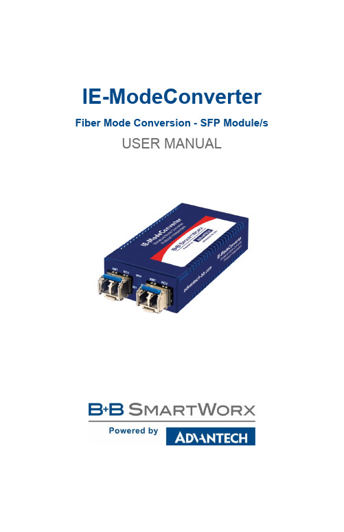
IE-ModeConverter Fiber Mode Conversion - SFP Module/s USER MANUALAdvantech B+B SmartWorx - Americas707 Dayton RoadOttawa, IL 61350 USAPhone1 (815) 433-5100Fax1 (815) 433-5105Advantech B+B SmartWorx - EuropeWestlink Commercial ParkOranmore, Co. Galway, IrelandPhone +353 91-792444Fax +353 91-792445************************CONTENTSAbout T h e IE-iMcV-MediaLinX & -iMcV-MediaLinX (4)Overview (4)Features (4)Applications (5)Installing the IE-ModeConverter (5)SFP Port Requirements (5)DIN Rail Mounting (5)DIN Rail - Cascading DC Power (6)Powering the IE-ModeConverter (6)Power Input Specifications (6)DC Terminal Block Option (7)DC Power Supply Precautions (7)LED Operation (8)Specifications (9)B+B SmartWorx Technical Support (10)Statements, Guidelines, Precautions, Regulatory (10)FCC Radio Frequency Interference Statement (10)Fiber Optic Cleaning Guidelines (11)Electrostatic Discharge Precautions (12)Regulatory, Standards, Compliances (13)ABOUT T H E IE-IMCV-MEDIALINX & -IMCV-MEDIALINX OVERVIEWThe IE-ModeConverter is a pure mode converter that converts any fiber optics type to any other fiber optics type. This product is a protocol independentconverter and is not intended for applications that require retiming or anyLayer 2 functions. The IE-ModeConverter supports extended temperature operation.The IE-ModeConverter requires two small form-factor (SFP) modules (sold separately and available from B+B SmartWorx), which provide greater fiber flexibility in the network environment. The hot-swappable nature of SFPs and the numerous fiber modes and types available in SFPs allow for easyconfiguration and future upgrading as network demands evolve. The SFP modules must be MSA-compliant and support the same speed range.•T he IE-ModeConverter operates as a mode converter only; and not as a rate converter.•T he IE-ModeConverter does not provide support for copper (TX) SFPs. NOTE: Some options require items that are sold separately, available from B+B SmartWorx.FEATURESThe IE-ModeConverter provides the ability to change optical transport characteristics using easy-to-install SFP devices. This mix-and-match functionality is only limited by available B+B SmartWorx’ SFP units.Key Features:•Uses Miniature Media Converter Form Factor.•Supports 7 to 50 VDC terminal block option with cascading power. •Supports external 5 VDC power option (not extended temperature). •Allows extended temperature range from -25 to +85 °C (-13 to +185 °F). •Uses all standard MSA-complaint SFP devices (excluding copper SFPs). •Provides extensive diagnostic LED functions.•Supports DIN rail mounting.APPLICATIONSThe standard application is the conversion of a short-range, multi-mode fiber interface to a long-range, single-mode fiber line. In addition, CWDM, DWDM or single-strand fiber can be supported with the appropriate SFP. This allows you to purchase low-cost, multi-mode fiber blade cards for your networkequipment and support long-distance, single-mode fiber links. INSTALLING THE IE-MODECONVERTERThe IE-ModeConverter installs anywhere as a standalone, table-top device, or on a DIN rail.As a standalone device, install it in locations with limited space.If multiple connections are required, use an IE-PowerTray/18 enclosure, (sold separately, available from B+B SmartWorx). The tray allows for 18conversions in a 1.5 rack unit of space. The units can also be powered by daisy-chaining DC power (see Cascading DC Power).NOTE: Some options require items that are sold separately, available from B+B SmartWorx.SFP PORT REQUIREMENTSThe IE-ModeConverter requires two SFP modules of the same speed: either two fast Ethernet (100Mbps) modules, or two Gigabit Ethernet (1000Mbps) modules. NOTE: Both SFPs must operate at the same speed.DIN RAIL MOUNTINGThe IE-ModeConverter can be mounted with twoDIN rail clips (hardware option, available from B+BSmartWorx). The DIN rail clips include screws toallow the installation on a DIN rail. Install the screwsinto DIN rail clips, which should be mountedperpendicular to the DIN rail. Snap the converteronto the clips. To remove the converter from the DINrail, place a flat-head screwdriver into the slot togently pry the converter from the rail.Note: DIN rail clips are designed for use on DIN-35 rail.DIN RAIL - CASCADING DC POW ERIf installing multiple IE-ModeConverters onDIN rail, you can use one DC input sourceand then cascade from one DC terminal blockto the next, until reaching the maximumelectrical current available.POWERING THE IE-MODECONVERTERThe IE-ModeConverter requires an external DC power source and has three powering options:•Universal AC power adapter w/ country specific clip (not included with module only version).•User supplied LPS DC power via a four-position DC power block.•Power from an IE- PowerTray/18 (optional, available from B+B SmartWorx)•Double-USB power cable (optional, available only from B+B SmartWorx).•IE-Power/5V DIN rail mount power supply, extended temperature (optional, from B+B) For extended temperature operation, the DC terminal block must be used because the supplied AC to DC converter is not rated for extendedtemperature operation. The power source used with the DC terminal block should be a Limited Power Source (LPS).POW ER INPUT SPECIFICATIONSPower Input Specifications TableAC Wall Adapter 100 to 240 ±10% VAC input, 5 VDC output, 2A maximum DC Terminal +7to+**************.Actualcurrentconsumptionmayvary depending on the type of SFP modules installed. Whennot using the supplied AC/DC converter, the externallysupplied DC power must be provided from an LPS source. DC Jack 5 VDCDouble-USB Power Cable Spec 500mANOTE: that the laptop or PC USB ports must be 2.0 or greater to provide sufficient power to the unit.Power Tray 18-SlotAC for MiniatureConverters125W, 20A @ 5VDC TERMINAL BLOCK OPTIONThe IE-ModeConverter DC power optionincludes a 7 to 50 VDC terminal block and astandard +5 VDC mini-jack. The DC terminalblock has multiple DC inputs intended forcascading DC power to an adjacent unit.Connect the power source to any one positiveand one negative terminal on the IE-ModeConverter.NOTE: When using stranded wire, the leads must be tinned. The chassis is not protected against mis-wiring; if mis-wired the chassis will not function. The chassis is internally connected to the negative power terminal.DC POW ER SUPPLY PRECAUTIONSThe following precautions must be observed when installing the chassis model with an internal DC power supply.1. Check nameplate ratings to ensure there is no overloading of supply circuits thatcould affect overcurrent protection and supply wiring.2. In addition, the following must be observed:a. Connect the equipment to a 35 to 50 VDC power source that is electrically isolated fromthe alternating current source. The 35 to 50 VDC power source is connected to a SELVDC source.b. Route input wiring to terminal block and secure in such a manner that it is protected fromdamage and stress. Do not route wiring past sharp edges or moving parts.c. Incorporate a readily accessible disconnect device, with a 3mm minimum contact gap inthe fixed wiring.Reliable Earthing of this equipment must be maintained. Particular attention should be given to supply connections when connecting to power strips, rather than direct connections to the branch circuit.LED OPERATIONThe IE-ModeConverter has four status LED indicators. Each LED is dual color and has three states: Off, red, or green. A loss of signal on one SFP causes the TX of the other SFP to turn Off. This action does not activate the red TX Fault LED.LEDCOLOR OR STATEPWRRedOffGreenCard does not pass the self-test.Unit does not have power.Power is applied to the card. All internal self-test functions must pass before the PWR LED is green.SD I SD 2LED transmitter has an active fault.No active fault on transmitter. LOS indication on receiver.Valid signal is detected by the SFP and LED transmitter is not in fault. MSA LEDs One or both SFPs are not installed or not detected. The TX inhibit must not be active if a SFP is missing.* Or, both SFPs are installed, but their speed settings are different. This condition disables both SFPs.N/AIndicates that both SFPs with the same speed are securely installed.* To help in troubleshooting, the Link Loss (LL) feature is always ON. That is, if a LOS is detected on an incoming SFP port, the optical transmitter on the other SFP port is turned OFF. This provides a Link Loss carry forward function to alert the device downstream of the existing problem. This function is "ON" in both directions at the same time. The LL function is inhibited if either SFP is not installed.SPECIFICATIONSOperating Temperature:-25 to +85 °C (-13 to +185 °F) - DC configuration-20 to +70 °C (-4 to +158 °F) - DIN rail mount power supply -10 to +50 °C (+14 to +122 °F) - with AC wall adapter Storage Temperature:-45 to +85 °C (-49 to +185 °F)Shipping Weight:0.11 kg (0.25 lb)Dimensions:2.11H x 4.57W x 8.51D cm (0.83H x 1.80W x3.35D in)B+B SMARTWORX TECHNICAL SUPPORTUSA/Canada: 1 (800) 346-3119 (Ottawa IL USA)Europe: +353 91 792444 (Ireland / Europe)Email: ************************Web: STATEMENTS, GUIDELINES, PRECAUTIONS, REGULATORYFCC RADIO FREQUENCY INTERFERENCE STATEMENT This equipment has been tested and found to comply with the limits for aClass A computing device, pursuant to Part 15 of the FCC Rules. These limits are designed to provide reasonable protection against harmful interference when the equipment is operated in a commercial environment. This equipment generates, uses and can radiate radio frequency energy and, if not installed and used in accordance with the instruction manual, may cause harmfulinterference to radio communications. Operation of this equipment in aresidential area is likely to cause harmful interference in which the user will be required to correct the interference at his own expense.Any changes or modifications not expressly approved by the manufacturer could void the user’s authority to operate the equipment.The use of non-shielded I/O cables may not guarantee compliance with FCC RFI limits. This digital apparatus does not exceed the Class A limits for radio noise emission from digital apparatus set out in the Radio InterferenceRegulation of the Canadian Department of Communications.Le présent appareil numérique n’émet pas de bruits radioélectriquesdépassant les limites applicables aux appareils numériques de classe Aprescrites dans le Règlement sur le brouillage radioélectrique publié par le ministère des Communications du Canada.FIBER OPTIC CLEANING GUIDELINESFiber Optic transmitters and receivers are extremely susceptible tocontamination by particles of dirt or dust, which can obstruct the optic path and cause performance degradation. Good system performance requires clean optics and connector ferrules.1. Use fiber patch cords (or connectors, if you terminate your own fiber)only from a reputable supplier; low-quality components can cause manyhard-to-diagnose problems in an installation.2. Dust caps are installed at the factory to ensure factory-clean opticaldevices. These protective caps should not be removed until the momentof connecting the fiber cable to the device. Should it be necessary todisconnect the fiber device, reinstall the protective dust caps.3. Store spare caps in a dust-free environment such as a sealed plasticbag or box so that, when reinstalled, they do not introduce anycontamination to the optics.4. If you suspect that the optics have been contaminated, alternatebetween blasting with clean, dry, compressed air and flushing withmethanol to remove particles of dirt.ELECTROSTATIC DISCHARGE PRECAUTIONSElectrostatic discharge (ESD) can cause damage to any product, add-inmodules or standalone units, containing electronic components. Alwaysobserve the following precautions when installing or handling these kinds of products:1. Do not remove unit from its protective packaging until ready to install.2. Wear an ESD wrist grounding strap before handling any module orcomponent. If a wrist strap is not available, maintain groundedcontact with the system unit throughout any procedure requiring ESDprotection.3. Hold the units by the edges; do not touch the electronic componentsor gold connectors.4. After removal, always place the boards on a grounded, static-freesurface, ESD pad or in a proper ESD bag. Do not slide the modulesor standalone units over any surface.WARNING! Integrated circuits and fiber optic components areextremely susceptible to electrostatic discharge damage. Donot handle these components directly unless you are a qualifiedservice technician and use tools and techniques that conform toaccepted industry practices.REGULATORY, STANDARDS, COMPLIANCES• SFP-MSA SFP standard (September 14, 2000)• SFF-8472 DDMI standard (Revision 1.0)• All SFPs used in this product should be certified to IEC 60825-1UL/cUL : Listed to Safety of Information Technology Equipment, including Electrical Business Equipment.CE : The products described herein comply with the Council Directive on Electromagnetic Compatibility (2004/108/EC) and the Council Directive on Electrical Equipment Designed for use within Certain Voltage Limits (2006/95/EC). Certified to Safety of Information Technology Equipment, Including Electrical Business Equipment. For further details, contact B+B SmartWorx.The products described herein comply with the Council Directive on Electromagnetic Compatibility (2004/108/EC).European Directive 2002/96/EC (WEEE) requires that any equipment that bears this symbol on product or packaging must not be disposed of with unsorted municipal waste. This symbol indicates that the equipment should be disposed of separately from regular household waste. It is the consumer’s responsibility to dispose of this and all equipment so marked through designated collection facilities appointed by government or localauthorities. Following these steps through proper disposal and recycling will helpprevent potential negative consequences to the environment and human health. Formore detailed information about proper disposal, please contact local authorities, waste disposal services, or the point of purchase for this equipment.© 2018 B+B SmartWorx – powered by Advantech. All rights reserved. The information in this document is subject to change without notice. B+B SmartWorx assumes no responsibility for any errors that may appear in this document. IE-ModeConverter is a trademark of B+B SmartWorx. Other brands or product names may be trademarks and are the property of their respective companies.Documentation Number: IE-ModeConverter_4618m。
Cisco兼容小型插槽可插拔(SFP)传输器模块指南说明书

33480 Rev. C https:/// Page 1 of 12User GuideTN ‐SFP ‐GE ‐x, TN ‐GLC ‐xx ‐xx, TN ‐CWDM ‐SFP ‐ 1xx0, TN ‐CWDM ‐100LX ‐1xx0 Series Ciscocompatible Small Form Factor Pluggable (SFP)Transceiver Modules∙Course Wavelength Division Multiplexing (CWDM) ITU Grid Compliant Wavelengths ∙Hot ‐Pluggable SFP Optical Transceiver With Duplex LC Connector ∙DMI (Digital Diagnostic Function) and DDMI (Digital Diagnostics Monitoring Interface) ∙Class 1 Laser International Safety Standard IEC ‐60825 Compliant ∙ Compatible with SFP Multi ‐Sourcing Agreement (MSA)ContentsIntroduction ............................................................................................................................................................... 1 Description ................................................................................................................................................................ 2 Specifications and Standards ..................................................................................................................................... 2 Optic Specifications ................................................................................................................................................... 2 SKUs ........................................................................................................................................................................... 3 Conformal Coated SFPs (TN ‐SFP ‐GE ‐x ‐C) .............................................................................................................. 4 Application: Fiber Connections with SFPs ................................................................................................................. 5 SFP Unpacking ........................................................................................................................................................... 5 SFP Installation .......................................................................................................................................................... 6 Cautions ................................................................................................................................................................ 6 Installing an SFP Module ....................................................................................................................................... 6 Fiber Cable Physical Characteristics ...................................................................................................................... 7 Connecting Fiber Cables ........................................................................................................................................ 7 Removing an SFP Module ..................................................................................................................................... 7 DMI (Diagnostic Monitoring Interface) ..................................................................................................................... 8 DDMI (Digital Diagnostics Monitoring Interface) ...................................................................................................... 9 Contact Us ............................................................................................................................................................... 10 For More Information .............................................................................................................................................. 10 Compliance Information .......................................................................................................................................... 10 UL Recognized ..................................................................................................................................................... 11 Declaration of Conformity................................................................................................................................... 12 Record of Revisions . (12)IntroductionTransition Networks TN ‐SFP ‐GE ‐x, TN ‐GLC ‐xx ‐xx, TN ‐CWDM ‐SFP ‐1xx0, and TNCWDM ‐100LX ‐1xx0 series small form factor pluggable (SFP) transceiver modules are designed to install in any SFP port. These TN ‐SFP modules allow a 1000Base ‐T, 1000Base ‐SX or LX interface to the network through the SFP connector. TN ‐SFP transceivers are designed for bi ‐directional, serial ‐optical data communications: Gigabit Ethernet or fiber channel at speeds up to 2.125 Gbps.33480 Rev. C / Page 2 of 12DescriptionAll of Transition’s SFPs and XFPs are compliant with the Multi ‐Sourcing Agreement (MSA) ensuringinteroperability with all other MSA compliant networking devices.All Transition Networks' SFP modules fully comply with the Multi ‐Sourcing Agreement (MSA).This compliance allows our SFP modules to be used in other MSA compliant SFP platforms. In addition, the SFP modules referenced in this manual (TN ‐SFP ‐GE ‐x, TN ‐GLC ‐xx ‐xx, TN ‐CWDM ‐SFP ‐1xx0, and TNCWDM ‐XL100‐1xx0) are also compatible with all Cisco SFP ‐based equipment supporting similar Cisco model SFPs, as well as its IOS software and SMARTnet. TN SFP modules ARE NOT Cisco OEM brand modules.Specifications and StandardsThe TN-GLC and TN-CWDM series SFPs was designed to meet these standards and specifications: StandardsCompliant with IEEE 802.3z 1000BASE-LX/ZX ComplianceIEC-60825; FDA 21; CFR 1040.10 and 1040.11. Compliant with Fiber Channel 1x SM-LC-L FC-PI. RoHS Compliant. Dimensions0.52 x 2.18 x 0.33 in (13.4 x 55.5 x 8.5 mm, Fiber) 0.95 x 2.8 x 0.54 in (14-0 x 71.1 13.7 mm, Copper) Weight1 oz. (28 g) approximately Voltage3.3V, Fiber 0.66 W; Copper 1.0 W Wavelength-6.0 < λc < +7.5 nm (TN-CWDM-xx-1xx0 only ) Operating TempTN-GLC-xx-xx, TN-CWDM-xx-1xx0: 0°C to 70°C (32°F to 158° F). TN-SFP-GE-x: -40°C to 85°C (-40° to 185°F). Storage Temp-40°C to 85°C (-40° to 185°F) Humidity5% to 95%, non-condensing MTBF MTBF for TN-GLC-LX-SM-RGD is 477,008 hours. Warranty LifetimeOptic Specificationsxx = center wavelength (λc)27 =1270nm39 = 1390nm 53 = 1530nm 29 = 1290nm 41 = 1410nm 55 = 1550nm31 = 1310nm 43 = 1430nm 57 = 1570nm 33 = 1330nm 47 = 1470nm59 = 1590nm 35 = 1350nm 49 = 1490nm 61 = 1610nm 37 = 1370nm 51 = 1510nmOptical Specs for all Transition Networks’ SFPs are listed at https:///lines/optical ‐devices/.SKUs# SKU Description1 TN-CWDM-SFP-12701000Base-LX/ZX Fibre Channel (LC) single mode 1270nm [80 km/49.7 mi.] Link Budget: 24.0 dB2 TN-CWDM-SFP-12901000Base-LX/ZX Fibre Channel (LC) single mode 1290nm [80 km/49.7 mi.] Link Budget: 24.0 dB3 TN-CWDM-SFP-13101000Base-LX/ZX Fibre Channel (LC) single mode 1310nm [80 km/49.7 mi.] Link Budget: 24.0 dB4 TN-CWDM-SFP-13301000Base-LX/ZX Fibre Channel (LC) single mode 1330nm [80 km/49.7 mi.] Link Budget: 24.0 dB5 TN-CWDM-SFP-13501000Base-LX/ZX Fibre Channel (LC) single mode 1350nm [80 km/49.7 mi.] Link Budget: 24.0 dB6 TN-CWDM-SFP-13701000Base-LX/ZX Fibre Channel (LC) single mode 1370nm [80 km/49.7 mi.] Link Budget: 24.0 dB7 TN-CWDM-SFP-13901000Base-LX/ZX Fibre Channel (LC) single mode 1390nm [80 km/49.7 mi.] Link Budget: 24.0 dB8 TN-CWDM-SFP-14101000Base-LX/ZX Fibre Channel (LC) single mode 1410nm [80 km/49.7 mi.] Link Budget: 24.0 dB9 TN-CWDM-SFP-14301000Base-LX/ZX Fibre Channel (LC) single mode 1430nm [80 km/49.7 mi.] Link Budget: 24.0 dB10 TN-CWDM-SFP-14501000Base-LX/ZX Fibre Channel (LC) single mode 1450nm [80 km/49.7 mi.] Link Budget: 24.0 dB11 TN-CWDM-SFP-14701000Base-LX/ZX Fibre Channel (LC) single mode 1470nm [80 km/49.7 mi.] Link Budget: 24.0 dB12 TN-CWDM-SFP-14901000Base-LX/ZX Fibre Channel (LC) single mode 1490nm [80 km/49.7 mi.] Link Budget: 24.0 dB13 TN-CWDM-SFP-15101000Base-LX/ZX Fibre Channel (LC) single mode 1510nm [80 km/49.7 mi.] Link Budget: 24.0 dB14 TN-CWDM-SFP-15301000Base-LX/ZX Fibre Channel (LC) single mode 1530nm [80 km/49.7 mi.] Link Budget: 24.0 dB15 TN-CWDM-SFP-15501000Base-LX/ZX Fibre Channel (LC) single mode 1550nm [80 km/49.7 mi.] Link Budget: 24.0 dB16 TN-CWDM-SFP-15701000Base-LX/ZX Fibre Channel (LC) single mode 1570nm [80 km/49.7 mi.] Link Budget: 24.0 dB17 TN-CWDM-SFP-15901000Base-LX/ZX Fibre Channel (LC) single mode 1590nm [80 km/49.7 mi.] Link Budget: 24.0 dB18 TN-CWDM-SFP-16101000Base-LX/ZX Fibre Channel (LC) single mode 1610nm [80 km/49.7 mi.] Link Budget: 24.0 dB 33480 Rev. C https:/// Page 3 of 1233480 Rev. C / Page 4 of 12Conformal Coated SFPs (TN-SFP-GE-x-C)∙ TN ‐SFP ‐GE ‐S ‐C∙ TN ‐SFP ‐GE ‐L ‐C∙ TN ‐SFP ‐GE ‐Z ‐CFeatures :∙ Extended operating temperature ‐40°C ~ +85°C∙ Compliant with IEEE802.3z Gigabit Ethernet Standard∙ SFF ‐8472 Digital Diagnostic Function (DMI)∙Conformal Coating (polyurethane coating Dymax 9482) forPCBs∙ Comply to EIA ‐364‐65B Class IIIASKUData Rate (Mbps) Media Wavelength (nM) Transmission Distance (Km) Temp. Range (°C) TN-SFP-GE-S-C1250Multi mode fiber 850 550 -40~85 TN-SFP-GE-L-C1250Single mode fiber 1310 10 -40~85 TN-SFP-GE-Z-C1250Single mode fiber 1550 80 -40~8533480 Rev. C https:/// Page 5 of 12 Application: Fiber Connections with SFPsSFPs are used with Gigabit Ethernet Switches and Routers, Fibre Channel Switch Infrastructure, xDSLapplications, Metro Edge Switching, etc.SFP UnpackingBefore you start installing the TN-SFP-xxx, verify that the package contains the following items:o One TN-10G-SFP-xxxo Two protective foam pieceso One Documentation PostcardPlease notify your sales representative immediately if any of the above items is missing or damaged. Save thepackaging for possible future use.33480 Rev. C / Page 6 of 12 SFP InstallationThe optical ports of the SFP transceiver must be terminated with an optical connector or with a dust plug. The SFP transceiver must be operated within the specified temperature and voltage limits.The Fiber Optic Association, Inc. provides a Technical Bulletin on “Guidelines for Testing and Troubleshooting Fiber Optic Installations ” at /tech/guides/TT3.pdf .There are other FOA Technical Bulletins that should be used as references for the design and planning of the network. These documents can be downloaded from the FOA Tech Topics website .Cautions∙The SFP tranceiver module is keyed to only be installed one way. However, if forced the wrong way, damage may occur. ∙Avoid getting dust or other contaminants into the fiber bore of the SFP transceiver module, as this will cause the optics to not operate properly. ∙Clean the optic surfacees of the optical fiber before you plug them back in to the optical bores of another SFP tranceiver module. ∙ Each port must match the wavelength specifications on the other end of the cable, and the cable must notexceed the specified cable length for reliable communications.Installing an SFP Module1. Attach an ESD-preventive wrist strap to your wrist and to the ESD ground connector or a bare metal surfaceon your chassis.2. Remove the SFP transceiver module from its protective packaging. Note: Do not remove the optical bore dustplugs until directed to do so in a later procedure.3. Check the slot orientation. Note that for some devices (e.g., S4224) some slots are “upside down” comparedto other slots.4. Position the SFP device at the desired installation slot, with the label facing correctly.5.Carefully slide the SFP device into the slot, aligning it with the internal installation guides.6. Ensure that the SFP device is firmly seated against the internal mating connector. To verify that the SFP isseated and latched properly. a ) Grasp the SFP by the sides and try to remove it without releasing the latch. b) If the SFP can not be removed, it is installed and seated properly. If the SFP can be removed, reinsert it andpress harder with your thumb; repeat if necessary until it is latched securely into the socket.7. Connect the fiber cable to the fiber port connector of the SFP device. Make sure the SFP release latch is inthe up (closed) position when you insert the cable connector into the SFP.8. Remove the dust plug from the connector. Save the dust plug for future use.9. Attach an appropriate cable into the SFP module port.10. Attach the other end of the cable into the other device.11. Observe the status LED(s). See the related manual for details.Fiber Cable Physical CharacteristicsThe fiber cable physical characteristics must meet or exceed IEEE 802.3ae specifications:∙Single mode fiber (recommended): 9 μm∙Multimode fiber (recommended): 62.5/125 μm∙Multimode fiber (optional): 100/140, 85/140, 50/125 μmWarning: Visible and invisible laser radiation when open. DO NOT stare into laser beam or view directly with optical instruments. Failure to observe this warning could result in damage to your eyes or blindness. Connecting Fiber CablesTo install the fiber cable, do the following:1.Locate the appropriate fiber cable.2.Install the cable as shown below.Removing an SFP ModuleCaution: Be careful when removing the SFP or SFP+ from a device. Some SFP transceiver module temperatures may exceed 160°F (70°C) and be too hot to touch with bare hands. Note: Do not remove and replace the SFP modules more often than necessary; excessive SFP removing and replacing can shorten the SFPs useful life.1.Attach an ESD‐preventive wrist strap to your wrist and to the ESD ground connector or a bare metal surfaceon your chassis.2.For future reattachment of fiber‐optic cables, note which connector plug is send (TX) and which is receive(RX).3.Remove the SFP transceiver module:a. If the SFP transceiver module has an actuator button latch, gently press the actuator button on the frontof the SFP transceiver module until it clicks and the latch mechanism releases the SFP transceiver module from the socket connector. Grasp the actuator button between your thumb and index finger, and carefully pull the SFP transceiver module straight out of the module slot.b. If the SFP transceiver module has a bail clasp latch, pull the latch out and down to eject the SFPtransceiver module from the socket connector. If the bail clasp latch is obstructed and you cannot use your index finger to open it, use a small, flat‐blade screwdriver or other long, narrow instrument to open the bail33480 Rev. C https:/// Page 7 of 1233480 Rev. C / Page 8 of 12 clasp latch. Grasp the SFP transceiver module between your thumb and index finger, and carefully remove it from the socket.4. Replace the Dust Plug.5. Place the removed SFP/SFP+ transceiver module in an antistatic bag or other protective package. DMI (Diagnostic Monitoring Interface)The following DMI port screen and explanation table contains brief definitions of the DMI support offered on some (SFP Transceiver Modules. For further information, see the help option on the CPSMM ‐xxx, SNMP agent, or Transition Networks Focal Point or ION System GUI. Note: This feature is not available on all devices and may vary between products. See the related manual for more information.DMI ParameterDescription DMI Rx PowerMeasured receive optical power in microwatts and in decibels relative to 1mW. DMI Rx Power AlarmAlarm status of measured receive optical power. DMI TempInternally measured temperature of transceiver in degrees Celsius and degrees Farenheit. DMI Temp Alarm Alarm status for internally measured temperature of the transceiver. DMI Bias CurrentMeasured transmit bias current in microamperes. DMI Bias AlarmAlarm status for measured transmit bias current for the interface. DMI Tx PowerMeasured transmit power in microwatts and in decibels relative to 1mW. DMI Tx Power AlarmAlarm status of measured transmit power. Rx Power IntrusionThreshold Tells the converter to stop passing traffic when the receive power drops below the new threshold. This feature is sometimes referred to as 'Intrusion Detection,' since tapping into a fiber to intercept traffic leads to a reduction in receive power. Thisvalue can be entered in microwatts or in decibels relative to 1mW.TN ‐SFP distances, TX power, RX power, and link budgets can be found on Transition Networks website, document at https:///lines/optical ‐devices/.The fiber optic transmitters on this device meet Class I Laser safety requirements per IEC ‐825/CDRH standards and comply with 21 CFR1040.10 and 21CFR1040.11.WARNING: Visible and invisible laser radiation when open. Do not stare into the beam or view the beam directly with optical instruments. Failure to observe this warning could result in an eye injury or blindness.IMPORTANT: Copper based media ports such as Twisted Pair (TP) Ethernet, USB, RS232, RS422, RS485, DS1, DS3, Video Coax, etc., are intended to be connected to intra‐building (inside plant) link segments that are not subject to lightening transients or power faults. Copper‐based media ports such as Twisted Pair (TP) Ethernet, USB,RS232, RS422, RS485, DS1, DS3, Video Coax, etc., are NOT to be connected to inter‐building (outside plant) link segments that are subject to lightening transients or power faults.DDMI (Digital Diagnostics Monitoring Interface)DDMI (Digital Diagnostics Monitoring Interface) provides enhanced digital DMI for optical transceivers which allows real time access to device operating parameters.The following DMI port screen and explanation table contains brief definitions of the DDMI support offered on some Small Form Factor Pluggable (SFP) Transceiver Modules. For further information, see the help option or User Guide for the S3290, S4140, S4212, and S4224. Note: This feature is not available on all devices and may vary between products. See the related manual for more information.The Transceiver Information and DDMI Information sections are described below.DDMI Parameter DescriptionDMI Rx Power (uW) Intrusion Threshold; a level for Rx Power on the Fiber port. If the DMI read value falls below the preset value, an intrusion is detected, and a trap is generated. The default is 0 uW. The range is 0 - 65,535 uW.Port The device’s port number.Vendor The SFP vendor’s name (e.g., Transition).Part Number The SFP vendor Part number provided by the SFP vendor (TN-10GSFP-SR). Serial Number The SFP Vendor Serial number provided by the SFP vendor (e.g., 8672105). Revision The SFP vendor Revision level for part number provided by the SFP vendor. Date Code The vendor's manufacturing date code (e.g., 2011-08-09).Transeiver The Transceiver compatibility (e.g., 1000BASE_SX or 10G).Current The current value of temperature, voltage, TX bias, TX power, and RX power.High Alarm Threshold The high alarm threshold value of temperature, voltage, TX bias, TX power, and RX power.High Warn Threshold The high warn threshold value of temperature, voltage, TX bias, TX power, and RX power.33480 Rev. C https:/// Page 9 of 12Low Warn Threshold The low warn threshold value of temperature, voltage, TX bias, TX power, and RX power.Low Alarm Threshold The low alarm threshold value of temperature, voltage, TX bias, TX power, and RX power.Contact UsTechnical SupportTechnical support is available 24‐hours a day: US and Canada: 1‐800‐260‐1312International: 00‐1‐952‐941‐7600Main Officetel: +1.952.941.7600 | toll free: 1.800.526.9267 | fax: 952.941.2322******************** | ************************** | ******************************AddressTransition Networks10900 Red Circle DriveMinnetonka, MN 55343, U.S.A.For More InformationTechnical information in this document is subject to change without notice. For more information see Transition Networks Optical Devices webpage.Compliance InformationClass I Laser ComplianceThis product has been tested and found to comply with the limits for FDA Class I laser for IEC60825, EN60825, and 21CFR1040 specifications.Translated Safety WarningsWarning Class I laser product. Advarsel Laserprodukt av klasse I.Waarschuwing Klasse‐I laser produkt. Aviso Produto laser de classe I.Varoitus Luokan I lasertuote. ¡Advertencia! Producto láser Clase I.Attention Produit laser de classe I Varning! Laserprodukt av klass I.Warnung Laserprodukt der Klasse I. Aviso Produto a laser de classe I.Avvertenza Prodotto laser di Classe I. Advarsel Klasse I laserprodukt.FCC RegulationsThis equipment has been tested and found to comply with the limits for a Class A digital device, pursuant to Part 15 of the FCC rules. These limits are designed to provide reasonable protection against harmful interference when the equipment is operated in a commercial environment. This equipment generates, uses and can radiate radio frequency energy and, if not installed and used in accordance with the instruction manual, may cause harmful interference to radio communications. Operation of this equipment in a residential area is likely to cause harmful interference, in which case the user will be required to correct the interference at the user's own expense.33480 Rev. C / Page 10 of 1233480 Rev. C https:/// Page 11 of 12Canadian RegulationsThis digital apparatus does not exceed the Class A limits for radio noise for digital apparatus set out on the radio interference regulations of the Canadian Department of Communications.Le présent appareil numérique n'émet pas de bruits radioélectriques dépassant les limites applicables aux appareils numériques de la Class A prescrites dans le Règlement sur le brouillage radioélectrique édicté par le ministère des Communications du Canada.European RegulationsWarningThis is a Class A product. In a domestic environment this product may cause radio interference in which case the user may be required to take adequate measures. Achtung !Dieses ist ein Gerät der Funkstörgrenzwertklasse A. In Wohnbereichen können bei Betrieb dieses Gerätes Rundfunkstörungen auftreten. In diesem Fäll is der Benutzer für Gegenmaßnahmen verantwortlich. Attention !Ceci est un produit de Classe A. Dans un environment domestique, ce produit risque de créer des interférences radioélectriques, il appartiendra alors à l'utilsateur de prende les measures spécifiques appropriées.In accordance with European Union Directive 2002/96/EC of the European Parliament and of the Council of 27 January 2003, Transition Networks will accept post usage returns of this product for proper disposal.The contact information for this activity can be found in the 'Contact Us' portion of this document.Der Anschluss dieses Gerätes an ein öffentlickes Telekommunikationsnetz in den EGMitgliedstaatenverstösst gegen die jeweligen einzelstaatlichen Gesetze zur Anwendung der Richtlinie 91/263/EWG zur Angleichung der Rechtsvorschriften der Mitgliedstaaten über Telekommunikationsendeinrichtungen einschliesslich der gegenseitigenAnerkennung ihrer Konformität.CAUTION: RJ connectors are NOT INTENDED FOR CONNECTION TO THE PUBLIC TELEPHONE NETWORK. Failure to observe this caution could result in damage to the public telephone network.Der Anschluss dieses Gerätes an ein öffentlickes Telekommunikationsnetz in den EGMitgliedstaatenverstösst gegen die jeweligen einzelstaatlichen Gesetze zur Anwendung der Richtlinie 91/263/EWG zur Angleichung der Rechtsvorschriften der Mitgliedstaaten über Telekommunikationsendeinrichtungen einschliesslich der gegenseitigen Anerkennung ihrer Konformität.UL RecognizedTN ‐SFP ‐10G ‐SR TN ‐SFP ‐10G ‐LR TN ‐GLC ‐T ‐MG TN ‐GLC ‐LH ‐SM TN ‐GLC ‐LX ‐SM ‐RGD TN ‐GLC ‐SX ‐MMTN ‐GLC ‐SX ‐MM ‐RGD TN ‐GLC ‐BX ‐U TN ‐GLC ‐BX ‐D TN ‐GLC ‐LHX ‐SM TN ‐SFP ‐GE ‐L TN ‐SFP ‐GE ‐STN ‐GLC ‐FE ‐100FX TN ‐GLC ‐BX ‐U ‐20 TN ‐GLC ‐BX ‐D ‐20 TN ‐GLC ‐LH ‐SMD TN ‐GLC ‐T TN ‐GLC ‐FE ‐100LXTN ‐SFP ‐OC3M TN ‐SFP ‐OC3S TN ‐SFP ‐SX TN ‐SFP ‐LX1 TN ‐SFP ‐LXB11 TN ‐SFP ‐LXB1233480 Rev. C / Page 12 of 12Declaration of ConformityRecord of RevisionsRev Date Notes A 9/30/13 Initial release.B 11/22/16 Update DoC, MTBF, and contact information and change format. C6/12/19Add UL and Conformal Coated SFP information.Trademarks: All trademarks and registered trademarks are the property of their respective owners.Copyright restrictions: © 2003-2019 Transition Networks. All rights reserved. No part of this work may be reproduced or used in any form or by any means - graphic, electronic or mechanical - without written permission from Transition Networks.。
SFP+_光模块测试指导PDF

SFP与SFP、XFP的区别10G模块经历了从300PinXENPAKX2XFP的发展最终实现了用和SFP一样的尺寸传输10G的信号这就是SFP。
SFP凭借其小型化低成本等优势满足了设备对光模块高密度的需求从2002年标准推了到2010年已经取代XFP成为10G 市场主流。
SFP光模块优点1、SFP具有比X2和XFP封装更紧凑的外形尺寸与SFP 尺寸相同2、可以和同类型的XFPX2XENPAK直接连接3、成本比XFPX2XENPAK 产品低。
SFP和SFP的区别1、SFP 和SFP 外观尺寸相同2、SFP协议规范IEEE802.3、SFF-8472 SFP 和XFP 的区别1、SFP和XFP 都是10G 的光纤模块且与其它类型的10G模块可以互通2、SFP比XFP 外观尺寸更小3、因为体积更小SFP将信号调制功能串行/解串器、MAC、时钟和数据恢复CDR以及电子色散补偿EDC功能从模块移到主板卡上4、XFP 遵从的协议XFP MSA协议5、SFP遵从的协议IEEE 802.3ae、SFF-8431、SFF-8432 6、SFP是更主流的设计。
3、SFP 协议规范IEEE 802.3ae、SFF-8431、SFF-8432。
一、目的高质量的完成维修任务保证模块能及时完成交付。
二、适用范围SFP 6G生产模块三、产品测试连接图装备测试连接图测试原理:信号发生器的输出信号经过RF Spliter射频分路器分成两路一路给待测模块发射端另外一端给光源。
待测模块发出的光信号给示波器进行相关参数光功率、消光比、交叉点等的测试。
光源发出的光信号进过衰减器再通过50:50光分路器一路给光功率计另外一路给被测模块接收端进行灵敏度测试。
四、模块功能介绍 4.1、简要说明模块在系统中的位置、作用、采用的标准SFP 6G光模块用于无线产品模块主要使用在中国的3G业务上为6Gbps可插拔收发一体的SFP光模块可插在使用6G单板上该版本可应用于无线TD系统中完成6G信号的光/电和电/光转换同时还完成模块自身的性能上报等功能。
Transition Networks TN-10GSFP-xxx SFP 光学传输器模块用户指南说

User GuideTN-10GSFP-xxxSFP Transceiver Modules•Hot-Pluggable SFP Optical Transceiver•Digital Diagnostic Function•Class 1 Laser International Safety Standard IEC-60825 Compliant•Compatible with Small Form Factor Pluggable Multi-Sourcing Agreement (MSA)Contents Introduction (1)Description (1)Specifications (2)Optical Specifications (2)Application: Fiber Connections with SFPs (2)SFP Unpacking (3)SFP Installation (3)Installing an SFP Module (3)Fiber Cable Physical Characteristics (4)Connecting Fiber Cables (4)Removing an SFP Module (5)Diagnostic Monitoring Interface (DMI) (6)DDMI (Digital Diagnostics Monitoring Interface) (7)Contact Us (8)For More Information (8)Compliance Information (8)Record of Revisions (9)IntroductionThe Transition Networks TN-10GSFP-xxx-TMs series small form factorpluggable (SFP) transceiver modules are designed to install in any SFP slot,and connect multimodeor single mode fiber-optic cable to the network throughthe SFP connector. The TN-10GSFP-xxx-TMs are designed for bi-directional,serial-optical data communications up to 10.5 Gbps.DescriptionAll of Transition’s SFPs and XFPs are compliant with the Multi-Sourcing Agreement (MSA) ensuring interoperability with all other MSA compliant networking devices.MSA Compliant 10G SFP+TN-10GSFP-SR: Compliant with IEEE 802.3ae 10GBASE-SR/SW. Link Length up to 300 m with OM3 multi-mode fiber; 82 m with OM2 multi-mode fiber; 33 m with OM1 multimode fiber.TN-10GSFP-LRx: Compliant with IEEE 802.3ae 10GBASE-LR/LW. Maximum Link Length of 70 KM.TN-10GSFP-LRxM: TN-10GSFP-LR1M (10km), TN-10GSFP-LR4M (40km), TN-10GSFP-LR8M (80Km), TN-10GSFP-LR8M-Cxx (multiple CWDM wavelengths - 47, 49, 51, 53, 55, 57, 59, 61). Compliant with IEEE802.3ae and IEEE802.3z.TN-10GSFP-LRxM-Dxx: TN-10GSFP-LR4M-D21 thru TN-10GSFP-LR4M-D60 and TN-10GSFP-LR8M-D21 thru TN-10GSFP-LR8M-D60: Compliant with IEEE802.3ae and IEEE802.3z. Channels 21-60 supported (e.g., TN-10GSFP-L4RM-D47 (40km) and TN-10GSFP-LR8M-D49 (80km)).SpecificationsThe TN-10GSFP-xxx was designed to meet these standards and specifications:Transition Networks' SFP modules fully comply with Multi-Sourcing Agreement (MSA). This compliance allows our SFP modules to be used in other MSA compliant SFP platforms without any problems.Optical SpecificationsThe Optical Spec for all Transition Networks’ SFPs are listed and maintained in a separate document at https:///sfp.pdf.Application: Fiber Connections with SFPsSFPs are used with Gigabit Ethernet Switches and Routers, Fibre Channel Switch Infrastructure, xDSL applications, Metro Edge Switching, etc.SFP UnpackingBefore you start installing the TN-10GSFP-xxx, verify that thepackage contains the following items:o One TN-10GSFP-xxxo Two protective foam pieceso One Documentation PostcardPlease notify your sales representative immediately if any of theabove items are missing or damaged. Save the packaging forpossible future use.SFP InstallationCautions•The SFP tranceiver module is keyed to only be installed one way. However, if forced the wrong way, damage may occur. •Avoid getting dust or other contaminants into the fiber bore of the SFP transceiver module, as this will cause the optics to not operate properly. • Be sure to clean the optic surfacees of the optical fiber before you plug them back in to the opticalbores of another SFP transceiver module. See the Fiber Optic Association, Inc. Cleaning Fiber Optic Connections page on the FOA website for more information.Installing an SFP Module1. Attach an ESD-preventive wrist strap to your wrist and to the ESD ground connector or a bare metalsurface on your chassis.2. Remove the SFP transceiver module from its protective packaging. Note: Do not remove the opticalbore dust plugs until directed to do so in a later procedure.3. Check the slot orientation. Note that for some devices (e.g., S4224) some slots are “upside down”compared to other slots.4. Position the SFP device at the desired installation slot, with the label facing correctly.5. Carefully slide the SFP device into the slot, aligning it with the internal installation guides. Triangleindicates bottomof SFP cageSFP Module Label side topof SFP moduleBaleClasp SwitchFully Inserted SFPSwitch6. Ensure that the SFP device is firmly seated against the internal mating connector. To verify that theSFP is seated and latched properly:a. Grasp the SFP by the sides and try to remove it without releasing the latch.b. If the SFP can not be removed, it is installed and seated properly. If the SFP can be removed,reinsert it and press harder with your thumb; repeat if necessary until it is latched securely into the socket.7. Connect the fiber cable to the fiber port connector of the SFP device. Make sure the SFP releaselatch is in the up (closed) position when you insert the cable connector into the SFP.8. Remove the dust plug from the connector. Save the dust plug for future use.9. Attach an appropriate cable into the SFP module port.10. Attach the other end of the cable into the other device.11. Observe the status LED(s). See the related manual for details.Fiber Cable Physical CharacteristicsThe fiber cable physical characteristics must meet or exceed IEEE 802.3ae specifications:•Single mode fiber (recommended): 9 μm•Multimode fiber (recommended): 62.5/125 μm•Multimode fiber (optional): 100/140, 85/140, 50/125 μmWarning: Visible and invisible laser radiation when open. DO NOT stare into laser beam or view directly with optical instruments. Failure to observe this warning could result in damage to your eyes or blindness. Connecting Fiber CablesTo install the fiber cable, do the following:1. Locate the appropriate fiber cable.2. Install the cable as shown below.Removing an SFP ModuleCaution: Be careful when removing the SFP or SFP+ from a device. Some SFP transceiver module temperatures may exceed 160°F (70°C) and be too hot to touch with bare hands. Note: • Do not remove and replace the SFP modules more often than necessary; excessive SFP removing and replacing can shorten the SFPs useful life.1. Attach an ESD-preventive wrist strap to your wrist and to the ESD ground connector or a bare metalsurface on your chassis.2. For future reattachment of fiber-optic cables, note which connector plug is send (TX) and which isreceive (RX).3. Remove the SFP transceiver module:a. SFP with an actuator button latch: gently press the actuator button on the front of the SFPtransceiver module until it clicks and the latch mechanism releases the SFP transceiver module from the socket connector. Grasp the actuator button between your thumb and index finger, and carefully pull the SFP transceiver module straight out of the module slot.b. SFP with a bail clasp latch: pull the latch out and down to eject the SFP transceiver module fromthe socket connector. If the bail clasp latch is obstructed and you cannot use your index finger to open it, use a small, flat-blade screwdriver or other long, narrow instrument to open the bail clasp latch. Grasp the SFP transceiver module between your thumb and index finger, and carefully remove it from the socket.4. Replace the Dust Plug.5. Place the removed SFP/SFP+ transceiver module in an antistatic bag or other protective package.Diagnostic Monitoring Interface (DMI)The following DMI port screen and explanation table contains brief definitions of the DMI support offered on some (SFP Transceiver Modules. For further information, see the help option on the CPSMM-xxx, SNMP agent, or Transition Networks Focal Point or ION System GUI. Note: This feature is not availableon all devices and may vary between products.DMI Parameter DescriptionDMI Rx Power Measured receive optical power in microwatts and in decibels relative to 1mW. DMI Rx PowerAlarmAlarm status of measured receive optical power.DMI Temp Internally measured temperature of transceiver in degrees Celsius and degrees Farenheit.DMI Temp Alarm Alarm status for internally measured temperature of the transceiver. DMI Bias Current Measured transmit bias current in microamperes.DMI Bias Alarm Alarm status for measured transmit bias current for the interface.DMI Tx Power Measured transmit power in microwatts and in decibels relative to 1mW. DMI Tx Power Alarm Alarm status of measured transmit power.Rx Power Intrusion Threshold Tells the converter to stop passing traffic when the receive power drops below the new threshold. This feature is sometimes referred to as 'Intrusion Detection,' since tapping into a fiber to intercept traffic leads to a reduction in receive power. This value can be entered in microwatts or in decibels relative to 1mW.TN-SFP distances, TX power, RX power, and link budgets can be found on Transition Netwoks’ website, document “SFP/XFP Fiber and Copper Connectors.” See https:///sfp.pdf.The fiber optic transmitters on this device meet Class I Laser safety requirements per IEC-825/CDRH standards and comply with 21 CFR1040.10 and 21CFR1040.11.WARNING: Visible and invisible laser radiation when open. Do not stare into the beam or view the beam directly with optical instruments. Failure to observe this warning could result in an eye injury or blindness. IMPORTANT: Copper based media ports such as Twisted Pair (TP) Ethernet, USB, RS232, RS422,RS485, DS1, DS3, Video Coax, etc., are intended to be connected to intra-building (inside plant) link segments that are not subject to lightening transients or power faults. Copper-based media ports such as Twisted Pair (TP) Ethernet, USB, RS232, RS422, RS485, DS1, DS3, Video Coax, etc., are NOT to be connected to inter-building (outside plant) link segments that are subject to lightening transients or power faults.DDMI (Digital Diagnostics Monitoring Interface)DDMI (Digital Diagnostics Monitoring Interface) provides enhanced digital DMI for optical transceivers which allows real time access to device operating parameters.The following DMI port screen and explanation table contains brief definitions of the DDMI support offered on some Small Form Factor Pluggable (SFP) Transceiver Modules. For further information, see the help option or User Guide for the S3290, S4140, S4212, and S4224. Note: This feature is not available on all devices and functionality may vary between products.The Transceiver Information and DDMI Information sections are described below. DDMI ParameterDescription DMIRx Power (uW) Intrusion Threshold; a level for Rx Power on the Fiber port. If the DMI read value falls below the preset value, an intrusion is detected, and a trap is generated. The default is 0 uW. The range is 0 - 65,535 uW. PortThe device’s port number. VendorThe SFP vendor’s name (e.g., Transition ). Part NumberThe SFP vendor Part number provided by the SFP vendor (TN-10GSFP-SR ). Serial NumberThe SFP Vendor Serial number provided by the SFP vendor (e.g., 8672105). RevisionThe SFP vendor Revision level for part number provided by the SFP vendor. Data CodeThe vendor's manufacturing date code (e.g ., 2011-08-09). TranseiverThe Transceiver compatibility (e.g., 1000BASE_SX or 10G ). CurrentThe current value of temperature, voltage, TX bias, TX power, and RX power. High Alarm ThresholdThe high alarm threshold value of temperature, voltage, TX bias, TX power, and RX power. High Warn ThresholdThe high warn threshold value of temperature, voltage, TX bias, TX power, and RX power. Low Warn ThresholdThe low warn threshold value of temperature, voltage, TX bias, TX power, and RX power. Low Alarm Threshold The low alarm threshold value of temperature, voltage, TX bias, TX power,and RX power.Contact UsTechnical Support: Technical support is available 24-hours a dayUS and Canada: 1-800-260-1312International: 00-1-952-941-7600Main Officetel: +1.952.941.7600 | toll free: 1.800.526.9267 | fax: 952.941.2322******************** | ************************** | ******************************AddressTransition Networks10900 Red Circle DriveMinnetonka, MN 55343, U.S.A.Web: https://For More InformationTechnical information in this document is subject to change without notice. For more information see the TN SFP Line Card or the SFP/XFP Landing page.Compliance InformationClass 1 Laser ComplianceThis product has been tested and found to comply with the limits for Class 1 laser for IEC60825,EN60825, and 21CFR1040 specifications.Translated Safety WarningsWarning Class 1 laser product. Advarsel Laserprodukt av klasse 1. Waarschuwing Klasse-1 laser produkt. Aviso Produto laser de classe 1.Varoitus Luokan 1 lasertuote. ¡Advertencia! Producto láser Clase I.Attention Produit laser de classe 1 Varning! Laserprodukt av klass 1.Warnung Laserprodukt der Klasse 1. Aviso Produto a laser de classe 1.Avvertenza Prodotto laser di Classe 1. Advarsel Klasse 1 laserprodukt.FCC RegulationsThis equipment has been tested and found to comply with the limits for a Class A digital device, pursuant to Part 15 of the FCC rules. These limits are designed to provide reasonable protection against harmful interference when the equipment is operated in a commercial environment. This equipment generates, uses and can radiate radio frequency energy and, if not installed and used in accordance with the instruction manual, may cause harmful interference to radio communications.Operation of this equipment in a residential area is likely to cause harmful interference, in which case the user will be required to correct the interference at the user's own expense.Canadian RegulationsThis digital apparatus does not exceed the Class A limits for radio noise for digital apparatus set out on the radio interference regulations of the Canadian Department of Communications.Le présent appareil numérique n'émet pas de bruits radioélectriques dépassant les limites applicables aux appareils numériques de la Class A prescrites dans le Règlement sur le brouillage radioélectrique édicté par le ministère des Communications du Canada.European RegulationsWarningThis is a Class A product. In a domestic environment this product may cause radio interference in which case the user may be required to take adequate measures.Achtung !Dieses ist ein Gerät der Funkstörgrenzwertklasse A. In Wohnbereichen können bei Betrieb dieses Gerätes Rundfunkstörungen auftreten. In diesem Fäll is der Benutzer für Gegenmaßnahmen verantwortlich.Attention !Ceci est un produit de Classe A. Dans un environment domestique, ce produit risque de créer des interférences radioélectriques, il appartiendra alors à l'utilsateur de prende les measures spécifiques appropriées.In accordance with European Union Directive 2002/96/EC of the European Parliament and of the Council of 27January 2003, Transition Networks will accept post usage returns of this product for proper disposal.The contact information for this activity can be found in the 'Contact Us' portion of this document.Der Anschluss dieses Gerätes an ein öffentlickes Telekommunikationsnetz in den EGMitgliedstaatenverstösst gegen die jeweligen einzelstaatlichen Gesetze zur Anwendung der Richtlinie 91/263/EWG zur Angleichung der Rechtsvorschriften der Mitgliedstaaten über Telekommunikationsendeinrichtungen einschliesslich der gegenseitigen Anerkennung ihrer Konformität.Record of RevisionsRev Date NotesA 9/30/13 Initial release.B 7/24/15 Add TN-10GSFP-xxT and update contact information and format.C 8/28/17 Add TN-10GSFP-LRxM information.D 3/7/18 Add TN-10GSFP-LRxM-Dxx (TN-10GSFP-LR4M-D21 thru TN-10GSFP-LR4M-D60 and TN-10GSFP-LR8M-D21 thru TN-10GSFP-LR8M-D60).TrademarksAll trademarks and registered trademarks are the property of their respective owners.Copyright restrictions© 2003-2018 Transition Networks.All rights reserved. No part of this work may be reproduced or used in any form or by any means - graphic, electronic or mechanical - without written permission from Transition Networks.。
H3C SFP[SFP+][XFP][SFP28]光模块及线缆安装指南(V1.10)-
![H3C SFP[SFP+][XFP][SFP28]光模块及线缆安装指南(V1.10)-](https://img.taocdn.com/s3/m/540d6eadfd0a79563c1e72e0.png)
H3C SFP/SFP+/XFP/SFP28光模块及线缆安装指南(CH&EN,V1.10)BOM:3105A00Yz请用户在安装SFP/SFP+/XFP/SFP28光模块或线缆前仔细阅读本手册,避免因安装步骤不当而造成器件损坏。
z不同产品可支持的光模块或线缆类型不同,具体请参见产品安装手册。
1佩戴防静电手腕为了避免静电对光模块或线缆中的电子器件造成损坏,除了对安装场所要采取防静电措施(如室内防尘、保持适当的温湿度)外,还要注意在安装或拆卸光模块或线缆时必须佩戴防静电手腕。
请将防静电手腕套在手腕上,拉紧锁扣,确认防静电手腕与皮肤有良好接触。
z如果设备上带有防静电手腕插孔,请将防静电手腕接地线缆的接地端子插入设备上的防静电手腕插孔。
z如果设备上没有防静电手腕插孔,请将防静电手腕接地线缆的接地端子夹在机架边框上,或采取其他措施使防静电手腕接地线缆良好接地。
防静电手腕的佩戴方式如图1 所示。
图1 防静电手腕配戴示意图如果用户还备有防静电手套,建议在安装光模块或线缆前先佩戴防静电手套,再套上防静电手腕,并确认防静电手腕与手套表面有良好接触。
2SFP/SFP+/XFP/SFP28光模块的安装和拆卸z在安装或拆卸光模块的过程中,请不要用手直接触摸光模块的金手指部分。
z建议用户在安装光纤前,不要将光模块光口上的保护胶塞拔出。
z建议用户不要将已插有光纤的光模块直接插入插槽,请拔出光纤后再进行安装。
2.1 安装光模块将光模块的拉手向上垂直翻起,卡住顶部卡扣,用手捏住光模块两侧,轻推入插槽,直至光模块与插槽紧密接触(可以感到光模块顶部和底部的弹片卡住插槽),如图2 所示。
如果光模块安装比较密集、空间有限时,也可使用手指轻推光模块前部,使其进入插槽。
图2 光模块安装示意图2.2 安装后的检查安装完成后,在设备上执行display transceiver interface命令,如显示信息中包含光模块的传输类型、接口类型、中心波长、传输距离等相关信息,则表示模块安装正确。
ModuleTek SFP-OC48-LR2-x-E10 光收发模块数据手册说明书

数据手册MODULETEK:SFP-OC48-LR2-x-E10OC-48LR-2/STM L-16.2SFP(小型可插拔)光收发模块,具有数字诊断功能产品简介ModuleTek的SFP-OC48-LR2-x-E10OC-48/STM-16SFP光收发模块设计符合OC-48LR-2/STM L-16.2 (2.488Gb/s)数据速率的ATM/SONET/SDH标准,模块通过2线串行总线实现数字诊断功能,为OC-48/STM-16单模应用提供了快速可靠的接口。
此外,该产品符合INF-8074i小型可插拔多源协议。
产品特性•高达2.488Gb/s的双向数据传输能力•符合ANSI-T1.646、ATM和SONET•用于OC-48/STM-16(2.488Gb/s)的SDH•符合SFP MSA•带温度控制功能的1550nm DFB激光发射器•热插拔设计•APD接收机•双LC接口•具有数字诊断功能•单模光纤上传输距离可达80km•单电源供电3.3V•符合RoHS标准•1类激光产品,符合EN60825-1标准•工作温度范围(外壳温度):商业温度等级:0◦C至70◦C工业温度等级:-40◦C至85◦C应用SONET OC48LR-2/SDH STM L-16.2摩泰光电用心做好每一次服务1订购信息型号产品ID 描述拉环颜色SFP-OC48-LR2-C-E10M420203OC48LR-2/STM L-16.2SFP LC 接口,1550nm 激光器,单模光纤上传输80km ,商业级绿色SFP-OC48-LR2-I-E10M420204OC48LR-2/STM L-16.2SFP LC 接口,1550nm 激光器,单模光纤上传输80km ,工业级绿色注:1.产品ID 为我司产品标准型号的简写订货号如需了解更多信息或订购上述产品,请联系:电子邮件:*******************摩泰光电官网:产品一般规格参数符号最小值典型值最大值单位备注数据速率DR 2.488Gb/s误码率BER 10−12工作温度T C 070◦C 1T I-4085◦C 1储存温度T STO −4085◦C2工作电流I CC 200300mA 3工作电压V CC 3.14 3.33.46V 最大电压V MAX−0.54.5V3注:1.外壳表面温度2.环境温度3.电接口传输距离数据速率光纤类型距离范围(km)备注2.488Gb/s9/125um 单模光纤80光学特性—发射机V CC=3.14V to3.46V,T参数符号最小值典型值最大值单位备注发射光功率P TX−23dBm1光中心波长λC14801580nm消光比ER9dB光谱宽度(−20dB)Δλ1nm边模抑制比SMSR30dB光信号上升/下降时间t r/t f300ps(20%-80%)注:1.平均光功率典型光眼图使用2.488Gb/s,PRBS223-1信号测试光学特性—接收机V CC=3.14V to3.46V,T参数符号最小值典型值最大值单位备注接收机过载P OL−9dBm光中心波长λC12601600nm接收灵敏度R X SEN−28dBm1 LOS信号生效LOS A−40dBmLOS信号失效LOS D−29dBmLOS信号迟滞区间LOS H0.5dB注:1.使用PRBS231−1测试模式测量,@2.488Gb/s,BER<10−12电气特性—发射机V CC=3.14V to3.46V,T参数符号最小值典型值最大值单位备注差分输入阻抗R IN100Ω单端输入摆幅V IN PP2501200mV发射机关闭电压V D V CC-1.3V CC V发射机使能电压V EN V EE V EE+0.8V发射机关闭等待时10us间电气特性—接收机V CC=3.14V to3.46V,T参数符号最小值典型值最大值单位备注单端输出摆幅V OUT PP300400800mV输出信号上升时间/下降时间t r/t f100170ps(20%-80%)LOS信号生效V LOS A V CC−0.5V CC HOST VLOS信号失效V LOS D V EE V EE+0.5VA0H 设备的寄存器说明IIC 地址字节大小寄存器名称寄存器描述取值(HEX)01IdentifierSFP 0311Extended Identifier使用IIC 接口0421Connector使用LC 连接器073-108Transceiver Transmitter Code 000C 000012000104111Encoding NRZ03121BR,Nominal 2.67Gb/s 的标称速率1B 131Rate Identifier 无速率选择功能00141Length(9μm)-km 在单模光纤传输80km 50151Length (9μm)-100m 在单模光纤传输80km FF 161Length (50μm)-10m 在多模光纤的传输距离00171Length (62.5μm)-10m 在多模光纤的传输距离00181Length (Copper)在铜缆的传输距离00191Reserved 未定义0020-3516厂商名称MODULETEKASCII Format361Transceiver 未定义0037-393Vendor OUI 厂商IEEE 公司ID 00000040-5516Vendor PN厂商产品型号由厂商定义56-594Vendor Revision Number厂商产品版本号由厂商定义60-612Wavelength 激光器的波长1550纳米060E 621Reserved 未定义00631CC_BASE 0-62字节的校验和由厂商定义64-652Transceiver Options1.Rx_LOS 信号监控2.Tx_FAULT 信号监控3.Tx_DIS 信号监控001A 661BR,max 高比特率余量00671BR,min 低比特率余量0068-8316Vendor SN 厂商序列号由厂商定义84-918Date code 日期代码由厂商定义921Monitoring TypeDOM 信息内部校准接收光功率测量使用平均光功率68931Enhanced Options 1.发射光与接收光Alarm 与Warning 监控2.Tx_DIS 信号监控与控制3.Rx_LOS 信号监控4.Tx_FAULT 信号监控F0941Compliance 按照12.0版本的SFF-8472定义08951CC_EXT 64-94字节的校验和由厂商定义96-12732Vendor Specific 厂商自定义区域由厂商定义128-255128Vendor Specific厂商自定义区域由厂商定义数字诊断功能SFP-OC48-LR2-x-E10支持SFP MSA中定义的2线串行通信协议,该产品通过地址为0xA2的2线接口访问数字诊断信息。
- 1、下载文档前请自行甄别文档内容的完整性,平台不提供额外的编辑、内容补充、找答案等附加服务。
- 2、"仅部分预览"的文档,不可在线预览部分如存在完整性等问题,可反馈申请退款(可完整预览的文档不适用该条件!)。
- 3、如文档侵犯您的权益,请联系客服反馈,我们会尽快为您处理(人工客服工作时间:9:00-18:30)。
sfp 光模块使用手册
一、概述SFp光模块是一种小型化、高性能的光纤模块,采用LC/UPC或APC连接器,具有低插入损耗、高带
宽和低成本等优点。
它支持多种传输距离和传输速率,可广泛应用于各种光纤网络中。
二、规格参数SFp光模块的规格参数如下:
传输速率:1Gbps、10Gbps、40Gbps等
传输距离:多模光纤(MMF)模式下支持2公里、5公里、10公里等多种距离;单模光纤(SMF)模式下支持10公里、40公里、80公里等多种距离
连接器类型:LC/UPC或APC
插入损耗:≤0.3dB
偏振模色散:≤0.5ps
回波损耗:≥50dB(UPC)/≥35dB(APC)
最大功耗:≤0.9W
三、使用方法使用SFp光模块前需要先确定网络设备的接口类型和传输距离,然后选择相应的光模块和光纤跳线。
以下是使用SFp光模块的步骤:
确定网络设备的接口类型和传输距离,选择相应的SFp 光模块和光纤跳线。
打开网络设备的机箱,找到光模块插槽,将光模块插入插槽中,确保模块与插槽对齐。
使用螺丝将光模块固定在插槽中。
使用光纤跳线连接光模块和光纤网络设备或光纤面板。
确保连接器端面清洁,插入时要轻、快,避免过度用力。
在连接完成后,测试光模块的连通性和传输速率,确保其正常工作。
在使用过程中,定期检查光模块和光纤跳线的连接情况,确保其保持良好状态。
四、注意事项在使用SFp光模块时,需要注意以下几点:
避免在高温和高湿度的环境下使用光模块,以免影响其性能和使用寿命。
在安装和拆卸光模块时,要轻拿轻放,避免剧烈震动或碰撞。
在使用过程中,要定期检查光模块和光纤跳线的连接情况,确保其保持良好状态。
在更换光模块时,要选择与原设备兼容的品牌和型号,以确保其正常工作。