SiliconLabs蓝牙Mesh应用实例
【应用方法】基于蓝牙mesh的智能室内灯控网络

基于蓝牙mesh的智能室内灯控网络前言全屋智能灯控是近年来家居智能化最典型最实用的设计概念。
智能灯控可以符合需求、细微地设定亮度和颜色,环境改变智能调整灯光。
因此比起传统的家庭灯控具有节能、便利、舒适的特点。
正因为这些优势特点,越来越多厂商开始投入智能灯控系统的开发领域。
采用蓝牙mesh网络技术能够自动快速进行蓝牙配对和建立网络连线,加速布局智能家庭生态系统。
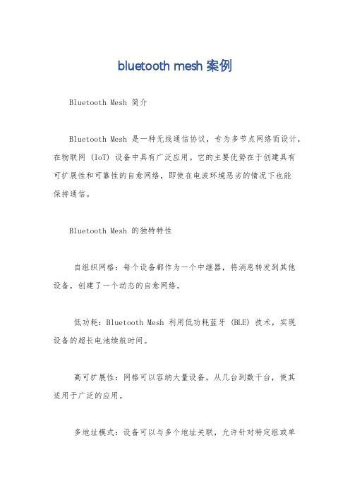
蓝牙Mesh网络介绍图1 mesh拓扑结构,多跳网络蓝牙Mesh网络是用于建立多对多设备通信的低功耗蓝牙BLE的网络拓扑。
它允许创建大型网络支持成千上万的蓝牙mesh设备间互相通信。
模块组网介绍亿佰特自主研发的E104-BT10蓝牙mesh自组网模块支持sig mesh V1.0标准,支持sig 标准HSL模型。
手机APP可任意节点代理入网,实现mesh网络远程控制,一键实现灯控应用场景。
智能灯控实施步骤1.初始化节点1,上电节点1串口发送02 c0 15,接收到03 43 15初始化成功。
图22.节点1入网,通过控制模块E104-BT10-G发送02 c0 09等待数秒,接收到0B 40 09 CAF7 EF FB F9 EC 00 02 03说明入网成功。
3.节点2入网,通过控制模块E104-BT10-G发送02 c0 09等待数秒,接收到0B 40 09 CAF7 EF FB F9 EC 00 05 03入网成功,同理其他节点入网操作也一样,收到类似返回码倒数第3、第2这两个字节表示入网地址。
图34.节点开关灯控制,E104-BT10-G或者手机做代理节点控制。
如E104-BT10-G发送指令09c1 00 02 82 02 01 00 00 00,返回08 41 00 02 00 01 82 04 01可控制节点1开启灯光,09 c1 00 02 82 02 00 00 00 00,返回08 41 00 05 00 01 82 04 00可控制节点1关闭灯光。
bluetooth mesh案例
bluetooth mesh案例Bluetooth Mesh 简介Bluetooth Mesh 是一种无线通信协议,专为多节点网络而设计,在物联网 (IoT) 设备中具有广泛应用。
它的主要优势在于创建具有可扩展性和可靠性的自愈网络,即使在电波环境恶劣的情况下也能保持通信。
Bluetooth Mesh 的独特特性自组织网格:每个设备都作为一个中继器,将消息转发到其他设备,创建了一个动态的自愈网络。
低功耗:Bluetooth Mesh 利用低功耗蓝牙 (BLE) 技术,实现设备的超长电池续航时间。
高可扩展性:网格可以容纳大量设备,从几台到数千台,使其适用于广泛的应用。
多地址模式:设备可以与多个地址关联,允许针对特定组或单个设备进行通信。
安全性:Bluetooth Mesh 采用稳健的安全协议,提供设备身份验证和消息加密,确保网络的安全性。
Bluetooth Mesh 的应用Bluetooth Mesh 的多功能性和可靠性使其成为各种 IoT 应用的理想选择,包括:智能照明:控制家庭或商业建筑中的照明,实现节能和自动化。
传感器网络:收集和监控来自环境传感器的数据,以进行预测性维护和流程优化。
资产跟踪:跟踪设备的位置和状态,防止丢失或盗窃。
工业自动化:连接工业设备,实现远程监控和控制,提高生产力和安全性。
家庭自动化:集成各种家居设备,提供便利和舒适的生活体验。
网络拓扑和设备类型Bluetooth Mesh 网络由三种类型的设备组成:中继器设备:作为网络骨干,中继消息并维护网络拓扑。
代理节点:连接到外部网络(例如 Wi-Fi 或以太网),充当网关。
最终节点:与用户交互或执行特定任务的设备,如灯泡或传感器。
网络拓扑可以是单跳、多跳或混合,取决于设备之间的距离和网络复杂性。
消息模型和发布/订阅Bluetooth Mesh 使用发布/订阅消息模型。
订阅者订阅特定的主题,发布者将消息发布到这些主题。
订阅者仅接收他们订阅的主题的消息,确保低功耗和网络效率。
Silicon Labs蓝牙GATT配置器用户指南说明书

UG438: GATT Configurator User’s Guide for Bluetooth ® LE and Bluetooth MeshThis guide provides the information needed to effectively use theBluetooth GATT ConfiguratorStudio® 5 with Bluetooth SDK 3.x and Bluetooth Mesh SDK 2.x. The GATT Configurator is an intuitive interface providing access to allthe Profiles, Services, Characteristics, and Descriptors as defined inthe Bluetooth specification. It also supports creating, importing, orexporting custom GATT profiles for Bluetooth applications. Thisguide reviews the user interface and covers some of the mostcommon uses of the Configurator, and the usage of the DynamicGATT Configurator.1 GATT Configurator OverviewThe GATT Configurator is a simple-to-use tool to help you build your own GATT database. A list of project Profiles/Services/Character-istics/Descriptors is shown on the left and details about the selected item is shown on the right.The GATT Configurator is composed of a Custom GATT editor on the left, showing a list of project Profiles/Services/Characteristics/De-scriptors, and a Settings editor on the right. A SIG selector allows you to add standard elements to the profile.An options menu is provided at the top of the Custom GATT editor.The Custom GATT editor is always visible, and the Settings editor opens by default.Figure 1.1: GATT Configurator with Settings EditorThe GATT Configurator menu is:1) Add an item.2) Duplicate the selected item.3) Move the selected item up.4) Move the selected item down.5) Import a GATT database.6) Add Predefined (opens the SIG editor).7) Delete the selected item.Click Add Predefined (6) to open the SIG selector.Figure 1.2: GATT Configurator with SIG Selector1.1 SIG SelectorThe SIG Selector displays a list of predefined Profiles, Services, Characteristics, and Descriptors. These items can be filtered, using the filter pane. Tabs allow you to switch between different lists. As shown in the following figure, the pane on the right side of the list displays textual information about the latest selection. To add an item to the Custom GATT editor, mouse over it and click + on the right. The item can then be edited in the Settings Section. The selected SIG service/characteristic/descriptor will be added under the highlighted pro-file/service/characteristic. Click < BACK to return to the Setting Editor.Figure 1.3: SIG Selector1.2 Custom GATT EditorThe Custom GATT Editor displays the items present in the current configuration file. This includes a Custom GATT Profile, Services, Characteristics, and Descriptors displayed as a hierarchical list. The order of items shown reflects the order in which they exist in the GATT database. When the Settings Editor is open, select an item to see its properties and configuration.Figure 1.4: GATT Custom GATT Editor with Characteristic SelectedThe * next to the configuration file name indicates unsaved changes in the configuration.Note: The Generic Attribute Service is not listed in the Custom GATT database structure (on the left in the previous figure). This is a special service that is maintained by the stack, and can be added by enabling the Generic Attribute Service slider in the settings of the Custom BLE GATT profile. Once enabled, the service will be part of the database. It still will not appear in the Custom GATT database structure, nor on iOS devices as iOS hides this service, but you may see it on Android devices, for example.Figure 1.5. Generic Attribute Service Enabled1.2.1 Contributed ItemsSome services are listed in the configurator as “contributed items”. This means that their content is defined in other components, and they cannot be edited from this view.1.3 Settings SectionThe Settings editor allows you to configure the properties of items such as Profiles, Services, Characteristics and Descriptors that are present in the Custom GATT editor. Selecting an item populates the relevant configuration options such as the name, ID, properties and capabilities. Any changes made in this section reflect immediately for the selected item. You can minimize the Custom GATT editor while editing if you want. All Characteristics for a Service are included in the same Settings editor pane.Figure 1.6: Settings Editor1.4 Generating the GATT DatabaseDatabase generation happens automatically when the configuration is saved. The generated source files can be found in the directory named “autogen”.Figure 1.7: Generated Files2 Use CasesThis chapter describes common tasks performed with the GATT Configurator.2.1 Drag and DropTo include predefined items from the source list in your application, drag and drop the item from the Source Section to the Custom GATT section. When you drag and drop a profile or a service, all the Characteristics and Descriptors in the levels underneath get included automatically. Maintaining the hierarchical structure, Descriptors can only be included under Characteristics, which go under Services.Figure 2.1: Drag and Drop a Service to Include all the ItemsWithin the Custom GATT section, drag and drop can be used to reorder items. This saves the trouble of including and configuring the item again. Similarly, an item can be duplicated and moved around in the section.2.2 Create New ItemUse the Add an item (1) menu option to add a new item in the Custom GATT editor. If the profile is selected, a new Service will be created. If a Service is selected, a new Characteristics is created under the selected item. Descriptors can only be created when you have selected a Characteristic.When a new item is selected, the Settings section displays the default properties of the item. Here the item can be configured as per the requirements.Figure 2.2: Default Values for a Newly Created CharacteristicThe application gets local access to the GATT database using the characteristic ID. You can enter this by selecting the checkbox and entering a unique ID.Figure 2.3: Characteristic ID EnabledUpon generation, this ID gets a macro in the gatt_db.h file as shown below.extern const struct bg_gattdb_def bg_gattdb_data;#define gattdb_service_changed_char 3#define gattdb_device_name 7#define gattdb_ota_control 21#define gattdb_custom_characteristic 24UUID or Universally Unique identifier are numbers used to identify Services, Characteristics, and Descriptors uniquely. There are two types of UUID:1. 16 bit: These 16-bit UUIDs are predefined by the Bluetooth SIG. Being short they are energy and memory efficient. For example, theBlood Pressure Service has a UUID of 0x1810 whereas the Battery level Characteristic has a UUID of 0x2A19.2. 128 bit: This overcomes the limitation of running out of 16-bit UUIDs and gives the power to declare your own UUIDs for CustomServices and Characteristics. These randomly generated UUIDs in the GATT Configurator are of version 4 (random) variant 1. You can use any UUID for a custom Service or Characteristic if it does not overlap with Bluetooth base UUID: xxxxxxxx-0000-1000-8000-00805F9B34FB.While there is no central authority ensuring other devices don’t use the same UUID, there is very little chance (1 in 340 undecillion) that two devices end up with the same UUID.2.3 Adding PermissionsPermissions define what actions can be performed for a given Characteristic or Descriptor. For example, in the Blood Pressure Profile, the Blood Pressure Feature has a Mandatory Read property. For more information about access types and security requirements see the Properties section of UG118: Blue Gecko Bluetooth® Profile Toolkit Developer's Guide.First the required access types can be enabled with the sliders, and then the security requirements can be selected with the checkboxes.Figure 2.4: Setting Permission for a Characteristic or DescriptorNote: The notify and indicate attribute is stored in the SIG defined Client Characteristic Configuration Descriptor (a descriptor with the UUID 0x2902, which will be autogenerated when notifications are enabled). If you manually add a CCCD to the characteristic, the de-scriptor’s value will overwrite this setting. A warning will be displayed on the UI for this case.2.4 Adding CapabilitiesBluetooth SDK 2.4 introduced a new feature called Polymorphic GATT that can be used to dynamically show or hide GATT Services and Characteristics. The GATT Configurator implements this feature using GATT capabilities. This section describes how to do it.To summarize how capabilities work, each Service/Characteristic can declare several capabilities and the state of the capabilities (ena-ble/disable) determines the visibility of those Services/Characteristics as a bit-wise OR operation. For example, the Service/Characteristic is visible when at least one of its capabilities is enabled and it is not visible when all its capabilities are disabled.Always start by declaring the GATT-level capabilities and defining their default value. Select the Custom BLE GATT profile, and click the + control in the "Capability declarations" table. After adding a capability, you can change the name and default value. For example, Appearance, Temperature_Measure and Tx_power are added to the profile as shown in the following figure.Figure 2.5: Declaring GATT-level CapabilitiesOnce those capabilities are added, they become available on each of the services and characteristics. They can be declared from the dropdown list in the Settings section, named “Characteristic capabilities”.On the Service and Characteristic level declared capabilities count as enabled, and the ones which were not selected are disabled.Figure 2.6: Including GATT-level Capabilities in a CharacteristicNote: The capabilities state should not be changed during a connection, as that can cause misbehavior. The safest way is to change the capabilities when no devices are connected.2.5 Including ServicesIn a Service definition, you can add one or more references to other services, using the Service includes feature. Include definitions consist of a single attribute (the include declaration) that contains all the details required for the client to reference the included service.Included services can help avoid duplicating data in a GATT server. If a service will be referenced by other services, you can use this mechanism to save memory and simplify the layout of the GATT server.Start by declaring an ID for each service that needs to be included. Services without an ID cannot be referenced. This is done by selecting the ID checkbox and providing an identifier text for the Service. Next, select the Service to be referenced from the dropdown list, named “Service includes”.Figure 2.7: Referencing a Service using Service Includes2.6 Import and Export a GATT DatabaseImport: The Import control in the Custom GATT toolbar allows you to import an existing GATT database, using a .btconf file. Note that this will overwrite the existing GATT data.Figure 2.8: Importing a GATT databaseExport: There is no separate export function. Another project can directly import the GATT database of this project (named gatt_config-uration.btconf)3 Dynamic GATT Configuration3.1 OverviewSilicon Labs Bluetooth SDK v3.2 introduced the ability to create the GATT database dynamically with Bluetooth APIs. These dynamically-created GATT attributes can coexist with a static database generated from a GATT XML file. In this case, the attribute table of the static database is placed at the beginning of the database. When new services and characteristics are created dynamically, they are added into the attribute table after the attributes of the static database.This feature is recommended for NCP projects. With this method, the target application where the GATT database is located does not need to be modified. Therefore, the database can be built from the host side with the APIs. In other cases, the GATT Configurator is the preferred solution.3.2 UsageThe “Dynamic GATT Database” feature is not included in projects by default. It needs to be installed from the Software Components tab.Figure 3.1: Installing the Dynamic GATT DatabaseOperations on the GATT database are done in a “session”. The changes are saved when a session is finished by “committing” the changes. Unsaved changes are invisible to a connected remote GATT client. The modifications only takes effect when the session is finished.Each added service and characteristic needs to be started with the appropriate API, or they will not be visible to the connected clients. This start and stop mechanism can be used to have a polymorphic GATT database, as the capability feature is not supported in the dynamic GATT databases.The following code snippet shows how to add the Health Thermometer Service and the Temperature Measurement characteristic dynam-ically to the database. See the Bluetooth API reference manual section "GATT Database" for more details.//create a session for the database updatesl_bt_gattdb_new_session(&session);//add the Thermometer service (UUID: 0x1809) to the database, as an advertised primary servicesl_bt_gattdb_add_service(session, sl_bt_gattdb_primary_service,SL_BT_GATTDB_ADVERTISED_SERVICE,2,uuid_service, &service);//add the Temperature measurement (UUID:0x2A1C) characteristic to the servicesl_bt_gattdb_add_uuid16_characteristic(session, service, SL_BT_GATTDB_CHARACTERISTIC_INDICATE,0, 0, uuid_characteristic, sl_bt_gattdb_fixed_length_value,1, 1, 0, &characteristic);//activate the new servicesl_bt_gattdb_start_service(session, service);//activate the new characteristicsl_bt_gattdb_start_characteristic(session, characteristic);//save changes and close the database editing sessionsl_bt_gattdb_commit(session);Silicon Laboratories Inc.400 West Cesar Chavez Austin, TX 78701USA IoT Portfolio /IoT SW/HW /simplicity Quality /quality Support & Community /communityDisclaimerSilicon Labs intends to provide customers with the latest, accurate, and in-depth documentation of all peripherals and modules available for system and software imple-menters using or intending to use the Silicon Labs products. Characterization data, available modules and peripherals, memory sizes and memory addresses refer to each specific device, and “Typical” parameters provided can and do vary in different applications. Application examples described herein are for illustrative purposes only. Silicon Labs reserves the right to make changes without further notice to the product information, specifications, and descriptions herein, and does not give warranties as to the accuracy or completeness of the included information. Without prior notification, Silicon Labs may update product firmware during the manufacturing process for security or reliability reasons. Such changes will not alter the specifications or the performance of the product. Silicon Labs shall have no liability for the consequences of use of the infor -mation supplied in this document. This document does not imply or expressly grant any license to design or fabricate any integrated circuits. The products are not designed or authorized to be used within any FDA Class III devices, applications for which FDA premarket approval is required or Life Support Systems without the specific written consent of Silicon Labs. A “Life Support System” is any product or system intended to support or sustain life and/or health, which, if it fails, can be reasonably expected to result in significant personal injury or death. Silicon Labs products are not designed or authorized for military applications. Silicon Labs products shall under no circumstances be used in weapons of mass destruction including (but not limited to) nuclear, biological or chemical weapons, or missiles capable of delivering such weapons. Silicon Labs disclaims all express and implied warranties and shall not be responsible or liable for any injuries or damages related to use of a Silicon Labs product in such unauthorized applications. Note: This content may contain offensive terminology that is now obsolete. Silicon Labs is replacing these terms with inclusive language wherever possible. For more information, visit /about-us/inclusive-lexicon-projectTrademark InformationSilicon Laboratories Inc.®, Silicon Laboratories ®, Silicon Labs ®, SiLabs ® and the Silicon Labs logo ®, Bluegiga ®, Bluegiga Logo ®, EFM ®, EFM32®, EFR, Ember ®, Energy Micro, Energy Micro logo and combinations thereof, “the world’s most energy friendly microcontrollers”, Redpine Signals ®, WiSeConnect , n-Link, ThreadArch ®, EZLink ®, EZRadio ®, EZRadioPRO ®, Gecko ®, Gecko OS, Gecko OS Studio, Precision32®, Simplicity Studio ®, Telegesis, the Telegesis Logo ®, USBXpress ® , Zentri, the Zentri logo and Zentri DMS, Z-Wave ®, and others are trademarks or registered trademarks of Silicon Labs. ARM, CORTEX, Cortex-M3 and THUMB are trademarks or registered trademarks of ARM Holdings. Keil is a registered trademark of ARM Limited. Wi-Fi is a registered trademark of the Wi-Fi Alliance. All other products or brand names mentioned herein are trademarks of their respective holders.。
Silicon Labs Bluetooth Xpress 模块设计指南说明书
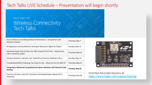
Tech Talks LIVE Schedule –Presentation will begin shortlyFind Past Recorded Sessions at:https:///support/trainingTopicDateHow to Measure and Debug Network Performance -Using Silicon Labs Network AnalyzerThursday, May 7RF Regulatory and Qualification Testing for Bluetooth, Zigbee & Z-Wave Tuesday, May 12Simplicity Studio Tips & Tricks: Our FAEs Know All The Tricks -Improve Your Life in Simplicity StudioThursday, May 14Wireless Module vs Wireless SoC Tradeoffs and Decision Making Criteria Tuesday, May 19Thunderboard BG22 Unboxing.You Have Our Kit… What Can You Do With It?Thursday, May 21Designing in Bluetooth using Bluetooth Xpress Modules with Minimal CodeWritingTuesday, May 26Overview of Silicon Labs Wi-Fi Solutions (Including Redpine Signals Wi-Fi Solutions)Thursday, May 28WELCOMEBluetooth Design with Minimal Code Writing using Bluetooth Xpress Modules M A Y2020A Silicon Labs Bluetooth Solution For Every CustomerTime-to-marketDesign flexibilityModuleDesign flexibilityServes full range of use cases Programming required Pre-certifiedSoCMaximum design flexibility Serves full range of use cases Programming requiredCertification requiredWireless XpressComplete configurable solution Optimized for select use cases Zero programming Pre-certifiedBlue Gecko Xpress -Introducing BGX13S and BGX13PBluetooth that just works.§BGX13P and BGX13S §Bluetooth LE features§Bluetooth 5: 1M, 2M, LR Coded PHY (125K/500K)§Multiset advertising§LE Secure connections and privacy §Xpress Streaming service for data§Operates in either central or peripheral role §Transmit at +8 dBm§Interface functionality§UART with flow control for data streaming §Xpress command API for configuration and control §Additional pins for connection state control§Configurable BLE performance, GPIO and status LEDs §NEW: I2C master support§NEW: Event Monitoring and User FunctionsZero firmware developmentUART to BluetoothFastest Time-to-Market§Fully integrated§Blue Gecko Xpress silicon§RF Matching + Shield + Antenna §Pre-certified (FCC, IC, CE)§Fast time-to-market§Reduced development cost§SiP and PCB modules§SiP offers industry-smallest form factor§PCB module for easiest manufacturing optionBGX13P BGX13S Description Bluetooth 5 PCB module Bluetooth 5 SiP module Size12.9 ×15.0 ×2.2 mm 6.5 ×6.5 ×1.4 mmLink type Max throughput (ack/noack)BGX-to-BGX 131/1000 kbits/s (2M PHY)BGX-to-Android 87/1000 kbits/s (2M PHY)BGX-to-iOS48/575 kbits/s (2M PHY)§Key link specifications§Encrypted communication only§Configure to enable/disable/clear bonds§Selectable advertising on 1M and/or LE Coded PHY §Preferred PHY configurable to 1M/2M/125K/500K §Adjustable scan/connection intervals §Just works and passkey pairing§Adjustable TX power §Current specs§Sleep mode, radio off: 2.8 uA§Sleep mode, advertising interval 500 ms: 90 uA §Connected, baud 9600, interval 1 s: 16 uA §Connected, baud 9600, interval 7.5 ms: 1.3 mA §Connected, baud >9600, interval 7.5 ms: 4.0 mAThroughput measurements(full characterization at https:///gecko-os/1/bgx/latest/throughput)Note: as of version 1.2, no-ack transfers provide in-channel acknowledgement to prevent packet lossUse case 1: Cable replacement with BGX13§Embedded UART-to-BLE§Host MCU only needs a UART §Optional flow control§Wireless cable replacement§BGX13 end-to-end BLE support§Configurable as central or peripheral§Central role simplified§Scan and connect in two commands§Data stream identical for peripheral and centralUse case 2: Easy BLE smartphone connections with BGX§Low-level BLE controlled by BGX§BGX13 handles advertising and connection§Optional control I/O and command interface§Mobile app development simplified§iOS and Android Mobile Xpress library§Mobile framework API to connect and communicateBGX can switch between BGX-to-phone and BGX-to-BGX in the same design Example: BGX-to-BGX star network design with phone app for product configurationXpress Configurator Makes Wireless Connectivity EasyContext-awaredocumentationOrder customsamples quickly Parameters organizedby functionT erminal window displaystransmitted dataT est on evaluation boardBGX Xpress command interface simplifies controlscanSuccess> ! # RSSI BD_ADDR Device Name # 1 -50 d0:cf:5e:82:8e:53 BGX-8E53# 2 -38 d0:cf:5e:82:8d:fd BGX-8DFD con 1Success> STREAM_MODEXpress command mode connection in 2 stepsHostBGXHost BGX§BGX13 provides a simple interface for key BLE connect and communicate features enable sensorsensor: enabled read sensor valuevalue: 23.4BGX stream mode App-specific communicationHost 1Host 2Host 1Host 2§BGX13 provides a robust and reliable link that just works §Application specific wireless communication made easy §Command API documentation available at Xpress Mobile Framework Speeds App Development§Available for iOS and Android§Mobile framework API includes:§Connect:connect()/disconnect()§Write:writeData()§Read:dataReadDelegate()§Modify port pins:writeCommand()§APIs for over-the-air updates§Supports Xpress interface I2C read/write commands§Source code for apps available on Github:§/SiliconLabs/wireless-xpressBGX Firmware and OTA Updates§Bluetooth Xpress run a closed firmware image§BGX Modules are debug locked and can only runfirmware images signed and encrypted by SiliconLabs§BGX Modules can be updated using the BGXCommander smartphone application§Custom User applications can access also accessfirmware updates using the Xpress MobileFrameworkDMSServerhttps:///gecko-os/1/bgx/latest/release-notesUARTI2CBGXSensorEmbedded systemBluetooth Low Energy linkSmart phoneVersion 1.2 features enable Bluetooth Xpress to function without an embedded host§Before version 1.2, all Bluetooth Xpress use cases required an embedded host §With I2C and event monitoring in version 1.2, the embedded host isn’t always needI2CBGXSensor Bluetooth Low Energy linkEmbedded systemVersion 1.2 features enable Bluetooth Xpress to function without an embedded host§Before version 1.2, all Bluetooth Xpress use cases required an embedded host §With I2C and event monitoring in version 1.2, the embedded host isn’t always needSmart phoneBLE-enabled Hall Effect Sensor Demo using Si7210Get Started with Bluetooth Xpress Development§Purchase Bluetooth Xpress evaluation kit§Download BGX commander app for Androidand iOS§Install latest version of Simplicity Studio to getXpress Configurator§Explore /bgx/ demos such as:§BGX-to-phone temperature sensor§BGX-to-BGX long range PHY controller§Contact sensor interface with BGX I2C§Xpress connect feature overviewGet started at /start-bgxMCU Host Examples in Simplicity StudioGet started at /start-bgxBluetooth Xpress Online ResourcesGitHub for interfacing code examples §https:///gecko-os/1/bgx/latest/§https:///SiliconLabs/wireless-xpressBGX Live DemoE A S Y H A R D WA R E D E S I G N PCB and SIP ModulesEasy PCB LayoutRegulatory CertificationC OM M O N U S E C A S E S Wire Replacement BGX-to-BGX BGX-to-Phone N O F I R M WA R E D E V E L O P M E N TXpress Configurator Xpress Streaming Service Xpress Mobile FrameworkEvent MonitoringBGX: In SummaryBG22 Virtual WorkshopLearn how to develop and deploy more powerful, efficient, and secure IoT products with your own BG22 Thunderboard–free for all registrants!New Sessions Opening in June10:00AM –11:30 AM CST -T, W, Th(Other sessions available for Asia Pacific and Europe)Register today! https:///about-us/events/virtual-bluetooth-workshopJoin Us: “What’s the Future of Smart Retail” PanelRegister at/applications/smart-industryQuestions? W W W.S I L A B S.C O MUseful Links§https:///start-bgx§https:///gecko-os/1/bgx/latest/§https:///documents/public/application-notes/an1157-developing-prod-using-bluetooth-xpress.pdf§https:///documents/public/quick-start-guides/qsg161-bgx13p-22ga-quick-start-guide.pdf§https:///SiliconLabs/wireless-xpress§https:///bluetooth/latest/。
Silicon Labs Bluetooth SDK 2.13.4.0 产品说明书

Bluetooth ® SDK 2.13.4.0 GAGecko SDK Suite 2.7 April 22, 2020Silicon Labs is a leading vendor in Bluetooth hardware and software technologies, used in products such as sports and fitness, consumer electronics, beacons, and smart home applications. The core SDK is an advanced Bluetooth 5-compliant stack that provides all of the core functionality along with multiple API to simplify development. The core func-tionality offers both standalone mode allowing a developer to create and run their appli-cation directly on the SoC, or in NCP mode allowing for the use of an external host MCU. Extensions to the SDK include Bluetooth Mesh and Apple ® HomeKit ® for customers seek-ing the additional capabilities.These release notes cover SDK version(s):2.13.4.0 released on April 22, 2020 2.13.3.0 released on March 20, 2020 2.13.2.0 released on February 21, 2020 2.13.1.0 released on January 24, 2020 2.13.0.0 released on December 13, 2019Compatibility and Use NoticesIf you are new to the Silicon Labs Bluetooth SDK, see Using This Release . Compatible Compilers:IAR Embedded Workbench for ARM (IAR-EWARM) version 8.30.1• Using w ine to build with the IarBuild.exe command line utility or IAR Embedded Workbench GUI on macOS or Linux could result inincorrect files being used due to collisions in wine’s hashing algorithm for generating short file names. • Customers on macOS or Linux are advised not to build with IAR outside of Simplicity Studio. Customers who do should carefullyverify that the correct files are being used. GCC (The GNU Compiler Collection) version 7.2.1, provided with Simplicity Studio.KEY FEATURESAdds directional priority PTA support for Wi-Fi CoexContents Contents1New Items (3)1.1New Features (3)1.2New APIs (3)2Improvements (5)2.1Changed APIs (5)3Fixed Issues (6)4Known Issues in the Current Release (8)5Deprecated Items (9)6Removed Items (10)7Using This Release (11)7.1Installation and Use (11)7.2Support (11)8Legal (12)8.1Disclaimer (12)8.2Trademark Information (12)1 New Items1.1 New FeaturesAdded in release 2.13.4.0Advertising channel index randomizationRandomly select advertising channel usage order.Added in release 2.13.3.0New Part SupportThis release supports the new EFR32[B|M]G22 device family and Thunderboard EFR32BG22. Additionally, support for BRD4180B and BRD4181B radio boards is added.Added in release 2.13.2.0Advertiser Random AddressApplications can set an advertiser’s random device address used in advertising packets.Added in release 2.13.0.0NVM3 support on EFR32[B|M]G1x devicesNVM3 is now supported on EFR32[B|M]G1x devices in addition to PS Store. These two data stores cannot be used simultaneously. The sample applications in the Bluetooth SDK continue to use PS Store by default. To replace PS Store with NVM3 please refer to AN1135: Using Third Generation Non-Volatile Memory (NVM3) Data Storage.Usage of NVM3 on EFR32[B|M]G1x devices is recommended only for new designs as there is no migration mechanism from PS to NVM3, when a new firmware is flashed via OTA or UART DFU. Doing DFU from PS to NVM3 will cause all PS data to be lost, which includes e.g., bonding information.Sleep TimerThe sleep timer (sl_sleeptimer.h) is a platform component providing single-shot and periodic timer services. It also provides APIs for reading current tick count and conversions between ticks and milliseconds.A Bluetooth application must include sleep timer component because the Bluetooth stack initializes and uses it for deep sleep. For more details, please refer to a Bluetooth SDK example such as the soc-empty.1.2 New APIsFor additional documentation and command descriptions please refer to the Bluetooth Software API Reference Manual.Added in release 2.13.4.0cmd_gatt_server_enable_capabilitiescmd_gatt_server_disable_capabilitiescmd_gatt_server_get_enabled_capabilitiesAdded in release 2.13.2.0cmd_le_gap_set_advertise_random_addresscmd_le_gap_clear_advertise_random_addressAdded in release 2.13.1.0cmd_coex_set_directional_priority_pulseAdded in release 2.13.0.0cmd_gatt_server_get_mtucmd_le_connection_read_channel_map cmd_coex_set_parametersImprovements 2 Improvements2.1 Changed APIsChanged in release 2.13.2.0Bluetooth Stack InitializationA hardware error is returned if HFRCODPLL is not configured to 80 MHz and set as the system clock source on EFR32[B|M]G21x. Changed in release 2.13.0.0cmd_system_linklayer_configureNew configuration key system_linklayer_config_key_set_priority_table is added for changing task priorities at run time.cmd_sm_store_bonding_configurationThe default maximum allowed bonding count is changed to 13.3 Fixed IssuesFixed in release 2.13.4.0467342 Fix OTA DFU update on BGM210P032.469935 Fix the issue that the thermometer RTOS example does not enter to deep sleep. The root cause is that the application’s idle hook uses OSIdleEnterHook(void), which is not called by the kernel if HW interrupt wakes up the device and no tasks are triggered by the interrupt. The fix is to use OSIdleContextHook(void). In this function, use a loop to set the stack tosleep, e.g.,void SleepAndSyncProtimer();void OSIdleContextHook(void){while (1) {/* Put MCU in the lowest sleep mode available, usually EM2 */SleepAndSyncProtimer();}}See thermometer RTOS example from the Bluetooth SDK.472920 Improve extended advertising packet reception during connections with very short intervals.475785 Fix an issue in Bluetooth RTOS adaptation that may cause incorrect conversion from sleeptimer frequency to OS frequency.477676 Improve the performance of Bluetooth connections using very short intervals on EFR32[B|M]G22.Fixed in release 2.13.3.0457174 Bluetooth applications are able to use RTCC on EFR32[B|M]G13 and EFR32[B|M]G21 again. To use RTCC, configure sleep timer to use PRORTC (#define SL_SLEEPTIMER_PERIPHERAL SL_SLEEPTIMER_PERIPHERAL_PRORTC). 466477 Improve scanning robustness.467371 Fix an issue that may cause the stack to use an invalid Bluetooth device address stored in PS key after the application is migrated from an old version of the SDK. This fix checks if an address is stored in PS, and removes the PS key if theaddress is invalid.467479 Prevent from erasing the next flash page after storage slot in OTA if the upgrade firmware is too big to fit storage slot. 468416 Function gecko_sleep_for_ms() now returns the sleep time in milliseconds. Previously a tick count value is returned. Fixed in release 2.13.2.0431452 TX power is now set to correct values corelating to the requests. Previously, when the requested TX Power was above 0 dBm, the actual transmit power may have deviated randomly.444469 Fix an issue that may cause the application to be unable to disconnect a Bluetooth connection when writing large amounts of data to characteristic values using the write-without-response command.446074 Fixed an issue that causes the stack to be unable to establish new connections after multiple connection drops.453828 Fix an issue that causes the application to be unable to confirm a characteristic indication in a low memory situation when writing large amounts of data to characteristic values using the write-without-response command.454960 Fix the tick rate RTOS_TICK_HZ in rtos_bluetooth.c to the correct value (1000).458216 Fix an issue in gecko_sleep_for_ms() which limits the sleep time to no more than 131 seconds.461654 BGAPI soft timers now work correctly regardless of the value SL_SLEEPTIMER_FREQ_DIVIDER is configured to in sleep timer.Fixed in release 2.13.1.0448020 In system_set_tx_power command, the stack now sets and returns the nearest possible value if the requested value is out of range.450903 Fix the issue when application compiles mbedTLS into source that uses AES with padding, mdebTLS context objects in Bluetooth stack may be corrupted and cause hard faults.450922 Use of GPCRC in Bluetooth stack is now thread safe.452831 Fix an issue in Apploader that causes application OTA update to fail if the data length in the first data packet is not multiple of four.455666 Fix a compatibility issue in Apploader with bootloader v1.10 on EFR32[B|M]G21. This issue causes OTA update to fail and the device to stay in OTA mode indefinitely.Fixed in release 2.13.0.0234520 In cmd_gatt_read_characteristic_value_by_uuid command, if multiple characteristic values are received, an evt_gatt_characteristic_value event is generated for each value. Previously only one event is generated for this case. 281984 First advertisement packet is now sent with the right timing in dynamic multi-protocol use cases.335894 Documentation fix to the lolen field in a BGAPI command header binary. The field specifies the minimal number of bytes the parameters take. It does not include the array data length if the command has an array type parameter.347844 Event evt_user_message_to_host can now be sent during user command handling in NCP target application.358171 Fix a random advertising hang issue which was observed when the application optimization build option was disabled or the device was exposed to low temperature.408097 Extended advertising now works in dynamic multi-protocol use cases.415583 The stack now returns out of memory error if the application sends a characteristic notification to all connections in low memory situation. Previously wrong state error was returned.420866 Improves robustness when streaming large data packets to and from a device which does not support data length exten-sion.421731 When sending a characteristic value notification to all connections using cmd_gatt_server_send_characteristic_notifica-tion command, the stack now returns success if devices are connected but none has enabled the notification. Previouslywrong state error was returned.425187 SL_BT_ prefix is added into the include guard in bg_version.h.425532 Fix whitelisting when an extended advertising packet does not contain an auxiliary pointer.430225 Fix CTUNE control using PS key on EFR32[B|M]G2x devices.430752 Fix an issue that the stack may lose a periodic advertising synchronization because the scanner uses highest priority for secondary tasks. This was solved by lowering the priority.434406 Remove the use of variable length array in the stack.436243 Fix a HW initialization issue in the soc-dtm example that causes incorrect timeout for incoming data.441445 Fix an advertisement data update race condition which causes no advertisement is sent out.445627 Repeated bonding attempts handling is now connection specific. After first failed attempt there is cool down period of 1 s.After second attempt this is doubled to 2 s then to 4 s etc. The maximum wait time is 64 s.450515 Fix an issue that causes BGTool does not run on Linux.Known Issues in the Current Release 4 Known Issues in the Current ReleaseIssues in bold were added since the previous release.243009 With certain events, GCC breakpoints cannot be set. Change optimization level to none in project settings 337467 MGM12P has poor signal strength when doing OTA withApploader.None360313 Default RAIL assertion (RAILCb_AssertFailed) enters an infinite loop causing the stack not responsive. Override RAIL assertion function in application space following these instructions.361592 The sync_data event does not report TX power. None368798 Example soc-thunderboard_sense_2 does not print float valuescorrectly in GCC project.In project C/C++ settings, enable the printf float option.396308 In NCP, BGAPI may be out of sync between the host and target when the target is reset in the middle of sending a BGAPImessage to host. The out of sync issue could cause the hostunable to communicate with the target. In NCP target, add a delay to flush NCP Tx queue after a system reset command is received.456701 Before gecko_init() is called, enabling busfaults generation onaccess to peripherals with clocks disabled causes a crash.Enable busfaults generation after gecko_init().463724 The Network Analyzer fails to decode a connection requestpacket when the connection is opened on LE Coded PHY.None464918 The stack has a performance issue that may cause advertisingto fail if the application is compiled without optimization (-O0).None470424 Connection drop may happen in rare cases if multiple simulta-neous connections use the same connection interval. Try to use different connection intervals in different connections to improve the robustness.Deprecated Items 5 Deprecated ItemsDeprecated in release 2.13.4.0Thunderboard Sense (SLTB001) and Thunderboard React (RD-0057-0201)Support for Thunderboard Sense (SLTB001) and Thunderboard React (RD-0057-0201) is now deprecated and will be removed in the next major SDK release.Removed Items 6 Removed ItemsNoneUsing This Release 7 Using This ReleaseThis release contains the following•Silicon Labs Bluetooth stack library•Bluetooth sample applicationsThis SDK depends on Gecko Platform. The Gecko Platform code provides functionality that supports protocol plugins and APIs in the form of drivers and other lower layer features that interact directly with Silicon Labs chips and modules. Gecko Platform components include EMLIB, EMDRV, RAIL Library, NVM3, and mbedTLS. Gecko Platform release notes are available through Simplicity Studio’s Launcher Perspective, under this SDK’s Release Notes doc header.For more information about the Bluetooth SDK see QSG139: Getting Started with Bluetooth® Software Development. If you are new to Bluetooth see UG103.14: Bluetooth LE Fundamentals.7.1 Installation and UseA registered account at Silicon Labs is required in order to download the Silicon Labs Bluetooth SDK. You can register at https:///apex/SL_CommunitiesSelfReg?form=short.Stack installation instruction are covered in QSG139: Getting Started with Bluetooth® Software Development.Use the Bluetooth SDK with the Silicon Labs Simplicity Studio V4 development platform. Simplicity Studio ensures that most software and tool compatibilities are managed correctly. Install software and board firmware updates promptly when you are notified. Documentation specific to the SDK version is installed with the SDK. Additional information can often be found in the knowledge base articles (KBAs). API references and other information about this and earlier releases is available on https:///.7.2 SupportDevelopment Kit customers are eligible for training and technical support. You can use the Silicon Labs Bluetooth LE web page to obtain information about all Silicon Labs Bluetooth products and services, and to sign up for product support.You can contact Silicon Laboratories support at /support.Legal 8 Legal8.1 DisclaimerSilicon Labs intends to provide customers with the latest, accurate, and in-depth documentation of all peripherals and modules available for system and software implementers using or intending to use the Silicon Labs products. Characterization data, available modules and peripherals, memory sizes and memory addresses refer to each specific device, and "Typical" parameters provided can and do vary in different applications.Application examples described herein are for illustrative purposes only.Silicon Labs reserves the right to make changes without further notice and limitation to product information, specifications, and descrip-tions herein, and does not give warranties as to the accuracy or completeness of the included information. Silicon Labs shall have no liability for the consequences of use of the information supplied herein. This document does not imply or express copyright licenses granted hereunder to design or fabricate any integrated circuits. The products are not designed or authorized to be used within any Life Support System. A "Life Support System" is any product or system intended to support or sustain life and/or health, which, if it fails, can be reasonably expected to result in significant personal injury or death. Silicon Labs products are not designed or authorized for military applications. Silicon Labs products shall under no circumstances be used in weapons of mass destruction including (but not limited to) nuclear, biological or chemical weapons, or missiles capable of delivering such weapons.8.2 Trademark InformationSilicon Laboratories Inc.®, Silicon Laboratories®, Silicon Labs®, SiLabs® and the Silicon Labs logo®, Bluegiga®, Bluegiga Logo®, Clockbuilder®, CMEMS®, DSPLL®, EFM®, EFM32®, EFR, Ember®, Energy Micro, Energy Micro logo and combinations thereof, "the world’s most energy friendly microcontrollers", Ember®, EZLink®, EZRadio®, EZRadioPRO®, Gecko®, ISOmodem®, Micrium, Preci-sion32®, ProSLIC®, Simplicity Studio®, SiPHY®, Telegesis, the Telegesis Logo®, USBXpress®, Zentri, Z-Wave and others are trade-marks or registered trademarks of Silicon Labs.ARM, CORTEX, Cortex-M0+, Cortex-M3, Cortex-M33, Cortex-M4, TrustZone, Keil and Thumb are trademarks or registered trademarks of ARM Holdings.Zigbee® and the Zigbee logo® are registered trademarks of the Zigbee Alliance.Bluetooth® and the Bluetooth logo® are registered trademarks of Bluetooth SIG Inc.Apple and HomeKit are registered trademarks of Apple Inc.All other products or brand names mentioned herein are trademarks of their respective holders.。
Silicon Labs以全集成Blue Gecko模块简化Bluetooth Smart设计

Silicon Labs以全集成Blue Gecko模块简化BluetoothSmart设计佚名【期刊名称】《单片机与嵌入式系统应用》【年(卷),期】2015(15)10【摘要】Silicon Labs(芯科科技有限公司)推出全集成、预认证的Bluetooth Smart模块解决方案,这为开发人员进行loT低功耗无线连接提供了便捷的实现途径。
新款BGM111模块是Silicon Labs高级Blue Gecko模块系列产品中的首款产品,具有极佳的集成度、灵活性、能效和工具链支持,且能轻松过渡到Blue Gecko片上系统(SoC)解决方案。
BGM111 Blue Gecko模块能够简化Bluetooth Smart设计,并大幅缩短各类应用产品上市时间,这些应用包括智能手机配件、信标设备(Beacon)、可连接家庭设备、健康和健身追踪器、个人医疗设备、汽车维修、工业传感器和售货点终端等。
【总页数】1页(P87-87)【关键词】Bluetooth;Silicon;Labs;全集成;模块;设计;无线连接;家庭设备【正文语种】中文【中图分类】TP332【相关文献】1.Silicon Labs CP21xx桥接芯片简化嵌入式USB接口设计\u-blox针对M2M市场推出优化的LISA 3G模块 [J],2.集成混合模拟信号模块,Silicon Labs32位MCU提供优秀设计灵活性 [J], 杨碧玲3.Silicon Labs新款Wireless Gecko SoC帮助开发人员解决多协议IoT设计挑战[J],4.Silicon Labs以全集成BIMe Gecko模块简化Bluetooth Smart设计 [J],5.Silicon Labs推出双模Bluetooth模块解决方案 [J],因版权原因,仅展示原文概要,查看原文内容请购买。
蓝牙Mesh网络技术的研究与应用
蓝牙Mesh网络技术的研究与应用一、蓝牙Mesh技术概述蓝牙Mesh网络技术是一种基于蓝牙低功耗技术的无线分布式网络协议,其主要目的是为了实现大规模的、开放型的蓝牙设备互联。
蓝牙Mesh技术采用分布式的网络结构,能够同时连接大量设备,实现设备之间的互相通信与数据交换,可以广泛应用于智能家居、物联网、灯光等领域。
二、蓝牙Mesh网络技术的优势1. 网络容量大蓝牙Mesh技术支持多达数以千计的设备并行相互通信,因此可以满足复杂场景下设备间数据传输和多用户同时控制的需求。
2. 低功耗作为低功耗蓝牙技术的一种补充,蓝牙Mesh网络技术可以支持广泛的设备类型并且能够进行有效的功率管理,因为它使用的是专为低功耗设备设计的数据报文格式。
3. 自组织网络蓝牙Mesh网络技术使用自组织网络结构,无需用户手动配置网络,可以根据设备的位置和空间关系自动连接组成网络。
4. 安全性高蓝牙Mesh网络技术具有较高的安全性能,每个设备都可以通过私有密钥来验证身份及加密通信数据。
三、蓝牙Mesh网络技术的应用场景1. 智能家居蓝牙Mesh技术可以应用于智能家居领域中,如家庭音响、灯光控制、智能门锁、安防设备等。
通过蓝牙Mesh网络互联,用户可以通过手机APP远程控制家庭设备,并实现设备之间的互相协作和数据同步。
2. 车联网蓝牙Mesh技术可应用于车联网中,如车内娱乐系统、车载照明系统、自动驾驶系统等。
通过蓝牙Mesh网络的连接,车内设备之间的控制与信息传递更加便捷、稳定。
3. 物联网蓝牙Mesh网络技术可以应用于物联网中,如安防监控系统、智能仓库系统等。
通过蓝牙Mesh网络的连接,设备之间的互相协作与数据同步更加便捷、快速。
四、蓝牙Mesh网络技术实现方式1. 分层设计蓝牙Mesh网络技术的设计采用分层方式,其中包括应用层、网络层、传输层和物理层。
应用层实现应用数据的传输,网络层实现节点寻址、路由选择、拓扑管理等,传输层实现数据可靠传输,物理层提供无线传输技术支持。
Silicon Labs EFR32MG 2.4 GHz 19.5 dBm 无线模组板参考手册说明书
EFR32MG 2.4 GHz 19.5 dBm Radio BoardBRD4151A Reference Manualance, low energy wireless solution integrated into a small formfactor package.By combining a high performance 2.4 GHz RF transceiver with an energy efficient 32-bitMCU, the family provides designers the ultimate in flexibility with a family of pin-compati-ble devices that scale from 128/256 kB of flash and 16/32 kB of RAM. The ultra-lowpower operating modes and fast wake-up times of the Silicon Labs energy friendly 32-bit MCUs, combined with the low transmit and receive power consumption of the 2.4GHz radio, result in a solution optimized for battery powered applications.To develop and/or evaluate the EFR32 Mighty Gecko, the EFR32MG Radio Board canbe connected to the Wireless Starter Kit Mainboard to get access to display, buttons andadditional features from Expansion Boards.Introduction 1. IntroductionThe EFR32 Mighty Gecko Radio Boards provide a development platform (together with the Wireless Starter Kit Mainboard) for the Silicon Labs EFR32 Mighty Gecko Wireless System on Chips and serve as reference designs for the matching network of the RF inter-face.The BRD4151A Radio Board is designed to operate in the 2400-2483.5 MHz band with the RF matching network optimized to operate with 19.5 dBm output power.To develop and/or evaluate the EFR32 Mighty Gecko, the BRD4151A Radio Board can be connected to the Wireless Starter Kit Main-board to get access to display, buttons and additional features from Expansion Boards and also to evaluate the performance of the RF interface.2. Radio Board Connector2.1 IntroductionThe board-to-board connector scheme allows access to all EFR32MG1 GPIO pins as well as the RESETn signal. For more information on the functions of the available pin functions, see the EFR32MG1 data sheet.2.2 Radio Board Connector Pin AssociationsThe figure below shows the pin mapping on the connector to the radio pins and their function on the Wireless Starter Kit Mainboard.GND F9 / PA3 / VCOM.#RTS_#CS 3v3UIF_BUTTON1 / PF7 / P36P200Upper RowNC / P38NC / P40NC / P42NC / P44DEBUG.TMS_SWDIO / PF1 / F0DISP_ENABLE / PD15 / F14UIF_BUTTON0 / PF6 / F12DISP_EXTCOMIN / PD13 / F10VCOM.#CTS_SCLK / PA2 / F8#RESET / F4DEBUG.TDO_SWO / PF2 / F2DISP_SI / PC6 / F16VCOM.TX_MOSI / PA0 / F6PTI.DATA / PB12 / F20DISP_EXTCOMIN / PD13 / F18USB_VBUS5VBoard ID SCLGND Board ID SDAUSB_VREG F7 / PA1 / VCOM.RX_MISO F5 / PA5 / VCOM_ENABLE F3 / PF3 / DEBUG.TDI F1 / PF0 / DEBUG.TCK_SWCLK P45 / NC P43 / NCP41 / NCP39 / NCP37 / High / SENSOR_ENABLEF11 / PF5 / UIF_LED1F13 / PF7 / UIF_BUTTON1F15 / PC8 / DISP_SCLK F17 / PD14 / DISP_SCS F19 / PB13 / PTI.SYNC F21 / PB11 / PTI.CLK GNDVMCU_INVCOM.#CTS_SCLK / PA2 / P0P201Lower RowVCOM.#RTS_#CS / PA3 / P2PD10 / P4PD11 / P6GND VRF_INP35 / PD15 / DISP_ENABLE P7 / PC9P5 / PC8 / DISP_SCLK P3 / PC7P1 / PC6 / DISP_SI P33 / PD14 / DISP_SCSP31 / PD13 / DISP_EXTCOMIN P29 / NCP27 / NC P25 / NC P23 / NC P21 / NC P19 / NC P17 / NC P15 / NC P13 / PC11P11 / PA1 / VCOM.RX_MISO P9 / PA0 / VCOM.TX_MOSI UIF_BUTTON0 / PF6 / P34UIF_LED1 / PF5 / P32UIF_LED0 / PF4 / P30DEBUG.TDO_SWO / PF2 / P28DEBUG.TMS_SWDIO / PF1 / P26DEBUG.TCK_SWCLK / PF0 / P24PTI.SYNC / PB13 / P22PTI.DATA / PB12 / P20PTI.CLK / PB11 / P18VCOM_ENABLE / PA5 / P16PA4 / P14PC10 / P12DEBUG.TDI / PF3 / P10PD12 / P8Figure 2.1. BRD4151A Radio Board Connector Pin MappingRadio Board Connector3. Radio Board Block Summary3.1 IntroductionThis section gives a short introduction to the blocks of the BRD4151A Radio Board.3.2 Radio Board Block DiagramThe block diagram of the EFR32MG Radio Board is shown in the figure below.Figure 3.1. BRD4151A Block Diagram3.3 Radio Board Block Description3.3.1 Wireless MCUThe BRD4151A EFR32 Mighty Gecko Radio Board incorporates an EFR32MG1P232F256GM48 Wireless System on Chip featuring 32-bit Cortex-M4 with FPU core, 256 kB of flash memory and 32 kB of RAM and a 2.4 GHz band transceiver with output power up to 19.5 dBm. For additional information on the EFR32MG1P232F256GM48, refer to the EFR32MG1 Data Sheet.3.3.2 LF Crystal Oscillator (LFXO)The BRD4151A Radio Board has a 32.768 kHz crystal mounted.3.3.3 HF Crystal Oscillator (HFXO)The BRD4151A Radio Board has a 38.4 MHz crystal mounted.3.3.4 Matching Network for 2.4 GHzThe BRD4151A Radio Board incorporates a 2.4 GHz matching network which connects the 2.4 GHz TRX pin of the EFR32MG1 to the one on-board printed Inverted-F antenna. The component values were optimized for the 2.4 GHz band RF performace and current con-sumption with 19.5 dBm output power.For detailed description of the matching network, see Chapter 4.2.1 Description of the 2.4 GHz RF Matching.| Smart. Connected. Energy-friendly.Rev. 1.7 | 33.3.5 Inverted-F AntennaThe BRD4151A Radio Board includes a printed Inverted-F antenna (IFA) tuned to have close to 50 Ohm impedance at the 2.4 GHz band.For detailed description of the antenna see Chapter 4.5 Inverted-F Antenna.3.3.6 UFL ConnectorTo be able to perform conducted measurements, Silicon Labs added an UFL connector to the Radio Board. The connector allows an external 50 Ohm cable or antenna to be connected during design verification or testing.Note: By default the output of the matching network is connected to the printed Inverted-F antenna by a series component. It can be connected to the UFL connector as well through a series 0 Ohm resistor which is not mounted by default. For conducted measurements through the UFL connector the series component to the antenna should be removed and the 0 Ohm resistor should be mounted (see Chapter 4.2 Schematic of the RF Matching Network for further details).3.3.7 Radio Board ConnectorsTwo dual-row, 0.05” pitch polarized connectors make up the EFR32MG Radio Board interface to the Wireless Starter Kit Mainboard. For more information on the pin mapping between the EFR32MG1P232F256GM48 and the Radio Board Connector, refer to Chapter 2.2 Radio Board Connector Pin Associations.4. RF Section4.1 IntroductionThis section gives a short introduction to the RF section of the BRD4151A.4.2 Schematic of the RF Matching NetworkThe schematic of the RF section of the BRD4151A Radio Board is shown in the following figure.U1BPath Inverted-F Antenna2.4 GHz Matching Figure 4.1. Schematic of the RF Section of the BRD4151A4.2.1 Description of the 2.4 GHz RF MatchingThe 2.4 GHz matching connects the 2G4RF_IOP pin to the on-board printed Inverted-F Antenna. The 2G4RF_ION pin is connected to ground. For higher output powers (13 dBm and above) beside the impedance matching circuitry it is recommended to use additional harmonic filtering as well at the RF output. The targeted output power of the BRD4151A board is 19.5 dBm. As a result, the RF output of the IC is connected to the antenna through a four-element impedance matching and harmonic filter circuitry.For conducted measurements the output of the matching network can also be connected to the UFL connector by relocating the series R1 resistor (0 Ohm) to the R2 resistor position between the output of the matching and the UFL connector.4.3 RF Section Power SupplyOn the BRD4151A Radio Board the supply pin of the RF Analog Power (RFVDD) is connected directly ot the output of the on-chip DC-DC converter while the supply for the 2.4 GHz PA (PAVDD) is provided directly by the mainboard. This way, by default, the DC-DC converter provides 1.8 V for the RF analog section, the mainboard provides 3.3 V for the PA (for details, see the schematic of the BRD4151A).4.4 Bill of Materials for the 2.4 GHz MatchingThe Bill of Materials of the 2.4 GHz matching network of the BRD4151A Radio Board is shown in the following table.Table 4.1. Bill of Materials for the BRD4151A 2.4 GHz 19.5 dBm RF Matching Network | Smart. Connected. Energy-friendly.Rev. 1.7 | 54.5 Inverted-F AntennaThe BRD4151A Radio Board includes an on-board printed Inverted-F Antenna tuned for the 2.4 GHz band. Due to the design restric-tions of the Radio Board the input of the antenna and the output of the matching network can't be placed directly next to each other. Therefore, a 50 Ohm transmission line was necessary to connect them. The resulting impedance and reflection measured at the output of the matcing network are shown in the following figure. As it can be observed the impedance is close to 50 Ohm (the reflection is better than -10 dB) for the entire 2.4 GHz band.Figure 4.2. Impedance and Reflection of the Inverted-F Antenna of the BRD4151A| Smart. Connected. Energy-friendly.Rev. 1.7 | 65. Mechanical DetailsThe BRD4151A EFR32 Mighty Gecko Radio Board is illustrated in the figures below.45 mmFigure 5.1. BRD4151A Top View5 mm ConnectorConnectorFigure 5.2. BRD4151A Bottom ViewMechanical DetailsRev. 1.7 | 7EMC Compliance 6. EMC Compliance6.1 IntroductionCompliance of the fundamental and harmonic levels is tested against the following standards:• 2.4 GHz:•ETSI EN 300-328•FCC 15.2476.2 EMC Regulations for 2.4 GHz6.2.1 ETSI EN 300-328 Emission Limits for the 2400-2483.5 MHz BandBased on ETSI EN 300-328 the allowed maximum fundamental power for the 2400-2483.5 MHz band is 20 dBm EIRP. For the unwan-ted emissions in the 1 GHz to 12.75 GHz domain the specified limit is -30 dBm EIRP.6.2.2 FCC15.247 Emission Limits for the 2400-2483.5 MHz BandFCC 15.247 allows conducted output power up to 1 Watt (30 dBm) in the 2400-2483.5 MHz band. For spurious emmissions the limit is -20 dBc based on either conducted or radiated measurement, if the emission is not in a restricted band. The restricted bands are speci-fied in FCC 15.205. In these bands the spurious emission levels must meet the levels set out in FCC 15.209. In the range from 960 MHz to the frequency of the 5th harmonic it is defined as 0.5 mV/m at 3 m distance (equals to -41.2 dBm in EIRP).Additionally, for spurious frequencies above 1 GHz, FCC 15.35 allows duty-cycle relaxation to the regulatory limits. For the EmberZNet PRO the relaxation is 3.6 dB. Therefore, the -41.2 dBm limit can be modified to -37.6 dBm.If operating in the 2400-2483.5 MHz band the 2nd, 3rd and 5th harmonics can fall into restricted bands. As a result, for those the -37.6 dBm limit should be applied. For the 4th harmonic the -20 dBc limit should be applied.6.2.3 Applied Emission Limits for the 2.4 GHz BandThe above ETSI limits are applied both for conducted and radiated measurements.The FCC restricted band limits are radiated limits only. Besides that, Silicon Labs applies those to the conducted spectrum i.e., it is assumed that, in case of a custom board, an antenna is used which has 0 dB gain at the fundamental and the harmonic frequencies. In that theoretical case, based on the conducted measurement, the compliance with the radiated limits can be estimated.The overall applied limits are shown in the table below.Table 6.1. Applied Limits for Spurious Emissions for the 2.4 GHz Band | Smart. Connected. Energy-friendly.Rev. 1.7 | 87. RF Performance7.1 Conducted Power MeasurementsDuring measurements, the EFR32MG Radio Board was attached to a Wireless Starter Kit Mainboard which was supplied by USB. The voltage supply for the Radio Board was 3.3 V.7.1.1 Conducted Measurements in the 2.4 GHz bandThe BRD4151A board was connected directly to a Spectrum Analyzer through its UFL connector (the R1 resistor (0 Ohm) was removed and a 0 Ohm resistor was soldered to the R2 resistor position). During measurements, the voltage supply for the board was 3.3 V provi-ded by the mainboard. The supply for the radio (RFVDD) was 1.8 V provided by the on-chip DC-DC converter, the supply for the power amplifier (PAVDD) was 3.3 V (for details, see the schematic of the BRD4151A). The transceiver was operated in continuous carrier transmission mode. The output power of the radio was set to the maximum level.The typical output spectrum is shown in the following figure.Figure 7.1. Typical Output Spectrum of the BRD4151AAs it can be observed, the fundamental is slightly lower than 19.5 dBm and the strongest unwanted emission is the double-frequency harmonic and it is under the -37.6 dBm applied limit.Note: The conducted measurement is performed by connecting the on-board UFL connector to a Spectrum Analyzer through an SMA Conversion Adapter (P/N: HRMJ-U.FLP(40)). This connection itself introduces approximately a 0.3 dB insertion loss.RF PerformanceRev. 1.7 | 97.2 Radiated Power MeasurementsDuring measurements, the EFR32MG Radio Board was attached to a Wireless Starter Kit Mainboard which was supplied by USB. The voltage supply for the Radio Board was 3.3 V. The radiated power was measured in an antenna chamber by rotating the DUT 360degrees with horizontal and vertical reference antenna polarizations in the XY , XZ and YZ cuts. The measurement axes are shown inthe figure below.Figure 7.2. DUT: Radio Board with the Wireless Starter Kit Mainboard (Illustration)Note: The radiated measurement results presented in this document were recorded in an unlicensed antenna chamber. Also the radi-ated power levels may change depending on the actual application (PCB size, used antenna, and so on). Therefore, the absolute levels and margins of the final application are recommended to be verified in a licensed EMC testhouse.7.2.1 Radiated Measurements in the 2.4 GHz bandFor the transmitter antenna, the on-board printed Inverted-F antenna of the BRD4151A board was used (the R1 resistor (0 Ohm) was mounted). During the measurements the board was attached to a Wireless Starter Kit Mainboard (BRD4001 (Rev. A02) ) which was supplied through USB. During measurements, the voltage supply for the board was 3.3 V provided by the mainboard. The supply for the radio (RFVDD) was 1.8 V provided by the on-chip DC-DC converter, the supply for the power amplifier (PAVDD) was 3.3 V (for details, see the schematic of the BRD4151A). The transceiver was operated in continuous carrier transmission mode. The output power of the radio was set to the maximum level.The results are shown in the table below.Table 7.1. Maximums of the Measured Radiated Powers of BRD4151AAs it can be observed, thanks to the high gain of the Inverted-F antenna, the level of the fundamental is higher than 19.5 dBm. The strongest harmonic is the double-frequency one but its level is under -45 dBm.RF PerformanceEMC Compliance Recommendations 8. EMC Compliance Recommendations8.1 Recommendations for 2.4 GHz ETSI EN 300-328 complianceAs it was shown in the previous chapter, the radiated power of the fundamental of the BRD4151A EFR32 Mighty Gecko Radio Board complies with the 20 dBm limit of the ETSI EN 300-328 in case of the conducted measurement but due to the high antenna gain the radiated power is higher than the limit by 2 dB. In order to comply, the output power should be reduced (with different antennas, de-pending on the gain of the used antenna, the necessary reduction can be different). The harmonic emissions are under the -30 dBm limit. Although the BRD4151A Radio Board has an option for mounting a shielding can, that is not required for the compliance.8.2 Recommendations for 2.4 GHz FCC 15.247 complianceAs it was shown in the previous chapter, the radiated power of the fundamental of the BRD4151A EFR32 Mighty Gecko Radio Board complies with the 30 dBm limit of the FCC 15.247. The harmonic emissions are under the -37.6 dBm applied limit both in case of the conducted and the radiated measurements. Although the BRD4151A Radio Board has an option for mounting a shielding can, that is not required for the compliance.Board Revisions 9. Board RevisionsTable 9.1. BRD4151A Radio Board RevisionsNote: The silkscreen marking on the board (e.g., PCBxxxx A00) denotes the revision of the PCB. The revision of the actual Radio Board can be read from the on-board EEPROM.Errata 10. ErrataTable 10.1. BRD4151A Radio Board ErrataDocument Revision History 11. Document Revision HistoryRevision 1.72016-11-20Minor editorial updates.Revision 1.62016-10-31Corrected error in radio board connector pinout diagram.Revision 1.52016-05-24Updating Board Revisions content. Fixing Errata description.Revision 1.42016-05-05Adding Introduction chapter; moving SoC Description chapter (short ver.) to Block Description chapter. Minor improvements.Revision 1.32016-02-11Addign RF Section Power Supply chapter. Minor improvements.Revision 1.22016-01-28Fixing image render problem.Revision 1.12015-25-25Updating Inverted-F Antenna Chapter and radiated measurement results based on board revision B02.Revision 1.02015-11-27Initial release.Table of Contents1. Introduction (1)2. Radio Board Connector (2)2.1 Introduction (2)2.2 Radio Board Connector Pin Associations (2)3. Radio Board Block Summary (3)3.1 Introduction (3)3.2 Radio Board Block Diagram (3)3.3 Radio Board Block Description (3)3.3.1 Wireless MCU (3)3.3.2 LF Crystal Oscillator (LFXO) (3)3.3.3 HF Crystal Oscillator (HFXO) (3)3.3.4 Matching Network for 2.4 GHz (3)3.3.5 Inverted-F Antenna (4)3.3.6 UFL Connector (4)3.3.7 Radio Board Connectors (4)4. RF Section (5)4.1 Introduction (5)4.2 Schematic of the RF Matching Network (5)4.2.1 Description of the 2.4 GHz RF Matching (5)4.3 RF Section Power Supply (5)4.4 Bill of Materials for the 2.4 GHz Matching (5)4.5 Inverted-F Antenna (6)5. Mechanical Details (7)6. EMC Compliance (8)6.1 Introduction (8)6.2 EMC Regulations for 2.4 GHz (8)6.2.1 ETSI EN 300-328 Emission Limits for the 2400-2483.5 MHz Band (8)6.2.2 FCC15.247 Emission Limits for the 2400-2483.5 MHz Band (8)6.2.3 Applied Emission Limits for the 2.4 GHz Band (8)7. RF Performance (9)7.1 Conducted Power Measurements (9)7.1.1 Conducted Measurements in the 2.4 GHz band (9)7.2 Radiated Power Measurements (10)7.2.1 Radiated Measurements in the 2.4 GHz band (10)8. EMC Compliance Recommendations (11)8.1 Recommendations for 2.4 GHz ETSI EN 300-328 compliance (11)8.2 Recommendations for 2.4 GHz FCC 15.247 compliance (11)9. Board Revisions (12)10. Errata (13)11. Document Revision History (14)Table of Contents (15)Silicon Laboratories Inc.400 West Cesar Chavez Austin, TX 78701USASimplicity StudioOne-click access to MCU and wireless tools, documentation, software, source code libraries & more. Available for Windows, Mac and Linux!IoT Portfolio /IoTSW/HW/simplicityQuality/qualitySupport and CommunityDisclaimerSilicon Labs intends to provide customers with the latest, accurate, and in-depth documentation of all peripherals and modules available for system and software implementers using or intending to use the Silicon Labs products. Characterization data, available modules and peripherals, memory sizes and memory addresses refer to each specific device, and "Typical" parameters provided can and do vary in different applications. Application examples described herein are for illustrative purposes only. Silicon Labs reserves the right to make changes without further notice and limitation to product information, specifications, and descriptions herein, and does not give warranties as to the accuracy or completeness of the included information. Silicon Labs shall have no liability for the consequences of use of the information supplied herein. This document does not imply or express copyright licenses granted hereunder to design or fabricate any integrated circuits. The products are not designed or authorized to be used within any Life Support System without the specific written consent of Silicon Labs. A "Life Support System" is any product or system intended to support or sustain life and/or health, which, if it fails, can be reasonably expected to result in significant personal injury or death. Silicon Labs products are not designed or authorized for military applications. Silicon Labs products shall under no circumstances be used in weapons of mass destruction including (but not limited to) nuclear, biological or chemical weapons, or missiles capable of delivering such weapons.Trademark InformationSilicon Laboratories Inc.® , Silicon Laboratories®, Silicon Labs®, SiLabs® and the Silicon Labs logo®, Bluegiga®, Bluegiga Logo®, Clockbuilder®, CMEMS®, DSPLL®, EFM®, EFM32®, EFR, Ember®, Energy Micro, Energy Micro logo and combinations thereof, "the world’s most energy friendly microcontrollers", Ember®, EZLink®, EZRadio®, EZRadioPRO®, Gecko®, ISOmodem®, Precision32®, ProSLIC®, Simplicity Studio®, SiPHY®, Telegesis, the Telegesis Logo®, USBXpress® and others are trademarks or registered trademarks of Silicon Labs. ARM, CORTEX, Cortex-M3 and THUMB are trademarks or registered trademarks of ARM Holdings. Keil is a registered trademark of ARM Limited. All other products or brand names mentioned herein are trademarks of their respective holders.。
蓝牙Mesh灯控方案详解
蓝牙Mesh灯控方案详解蓝牙技术受益于其智能、低功耗、高连接速度等特性,在物联网市场呈现爆发式增长是物联网工程师有目共睹的。
在蓝牙领域另一热门关键词就是Mesh技术。
自蓝牙技术联盟宣布蓝牙(Bluetooth®)技术开始全面支持Mesh网状网络以来,基于蓝牙Mesh的面向多种应用解决方案正在井喷,天工测控作为一家致力于GNSS模块、WiFi 模块、蓝牙模块研发和产品解决方案制定的专业技术公司也推出了自己的蓝牙Mesh灯控方案。
目前,蓝牙技术已被广泛应用于包括消费电子、汽车电子、医疗设备、智能家居甚至是工业领域在内的所有物联网智能产品中。
蓝牙Mesh智能灯,只是智能家庭设备的开始,采用蓝牙Mesh方案的智能家庭设备,能够自动快速进行蓝牙配对和建立网络连线,加速布局智能家庭生态系统。
蓝牙Mesh灯控方案蓝牙Mesh网络是用于建立多对多(many:many)设备通信的低能耗蓝牙(Bluetooth Low Energy,也称为Bluetooth LE)新的网络拓扑。
它允许您创建基于多个设备的大型网络,网络可以包含数十台,数百甚至数千台蓝牙Mesh设备,这些设备之间可以相互进行信息的传递。
蓝牙Mesh是蓝牙5规范的一部分,专门为传输灯具调光或开关指令、传感器信息或设备ID等小数据包优化。
在蓝牙Mesh灯控方案中,需要将蓝牙Mesh模块SKB369内置在LED灯内,用户通过手机连接Mesh网络中任何一个LED灯,就可以控制Mesh网络中任意一个或一组灯;蓝牙开关可以作为一个节点,控制Mesh网络中所有灯的开关,或者设置不同的场景模式;用户还可以对Mesh网络中的LED灯进行分组控制;可以对Mesh网络中的LED灯进行调光、调色;设置不同的场景模式;定时开关等操作。
由于蓝牙Mesh 是在低功耗的基础之上开发出来的,与核心规格版本4.0及更高版本兼容。
而功耗性也非常理想,具有极佳的省电功能。
这点从蓝牙Mesh模块SKB369的参数上得到了很好的体现,SKB369不同模式下的功耗:传输模式:0.7mA;广播模式:0.21mA;空闲模式:2uA;休眠模式:0.2uA。
智能家居通信:蓝牙mesh网络无限数据传输通信协议
智能家居通信:蓝牙mesh网络无限数据传输通信协议家庭智能自动化是一个关键市场,但任何小型商业系统都可以利用低功耗蓝牙技术在家庭大小的空间内进行通信。
因此,虽然BLE可能不适合大规模养殖,但它非常适合监测小型商业温室。
它还可以为正在配置IoT设备的安装人员提供本地通信,这些设备通常通过远程协议(如Zigbee mesh或蜂窝移动数据)进行通信。
蓝牙mesh网络蓝牙Mesh (BT Mesh)是一种非常新的协议。
它扩展了简单的点对点BLE,使用额外的路由和网络形成标准来创建网状网络,其中节点可以作为中继,将网络扩展到任何一个设备的范围之外。
BT Mesh在总体功能和架构上与Zigbee大体相似,但有几个非常重要的区别。
一个BT Mesh网络理论上可以支持超过32000个节点,但是像其他协议一样,带宽和物理空间的实际限制通常会使单个网络的设备数量保持在几百个。
蓝牙mesh网的优点以网状形式形成的网络不受任何单个无线节点范围的限制。
相反,每个节点可以将消息转发和路由到远远超出其名义范围的目的地,形成非常大的物理网络。
因为Bluetooth Mesh 基于BLE,它继承了该协议的许多优点,包括低能耗、良好的安全性、信标支持和普及的底层文档。
BT Mesh网络是自形成和自修复的,在与Zigbee类似的存储和转发父/子关系中为终端设备提供睡眠支持。
蓝牙mesh网的局限性蓝牙Mesh仍然是一个新协议,它仍在改进和修订中。
它还没有得到广泛支持,这意味着OEM设备、网关和手持设备还不太可能完全兼容。
随着该方案获得关注,这一情况可能会得到改善;然而,对于目前设计的应用程序来说,这确实是一个值得关注的问题。
“mesh网络”协议使网络设计更简单,但与完全路由的网状协议(如Zigbee)相比,它在效率和电力使用方面存在权衡。
任何路由设备都必须由电源供电,而不是靠电池运行,因为与Zigbee节点一样,BT Mesh路由器不允许休眠。
- 1、下载文档前请自行甄别文档内容的完整性,平台不提供额外的编辑、内容补充、找答案等附加服务。
- 2、"仅部分预览"的文档,不可在线预览部分如存在完整性等问题,可反馈申请退款(可完整预览的文档不适用该条件!)。
- 3、如文档侵犯您的权益,请联系客服反馈,我们会尽快为您处理(人工客服工作时间:9:00-18:30)。
1 Silicon Labs公司的套件及芯片
Silicon Labs公司提供的蓝牙Mesh标准协议目前已 经推出第二版正式SDK,加入了调光、调色功能,标志 着蓝牙Mesh在Lighting(照明)上的应用更加成熟; 也加入了友员节点、低功耗节点,低功耗应用的实现也 令蓝牙Mesh在Lighting领域的产品化成为现实。
Silicon Labs公司在蓝牙Mesh应用上有 EFR32MG、EFR32BG系列SoC和BGM系列模块,其中 性价比最高的为EFR32BG13系列,并提供了相应的开 发套件和例程,能大大提高蓝牙Mesh产品的开发速 度。该SoC集成了蓝牙5.0 2.4 GHz RF硬件,内置PA和 巴伦电路,RF外围器件只需要增加2个电感和1个电 容,无需客户在射频方面投入不必要的精力。
2 在照明领域应用蓝牙Mesh实例
无论是在工业照明、商业照明还是在家庭照明中, 实际灯的数量和开关的数量都远远超过初战演示,而且 照明场景也远远复杂过初战演示。接下来,我们结合案 例实现一个应用实例。
①根据Silicon Labs公司提供的硬件资料重新制作 了合乎产品尺寸的PCB(印制板),由于该SoC在无线 方面集成了PA(功率放大器)和巴伦电路,外围电路 相当简单,基本不需要进行任何硬件调试,一次PCB制 作成功率相当高。
引言
物联网发展如火如荼的今天,怎样可以联接大量节 点,又可以适应不同节点的特点的问题?这不可避免地 摆在了所有的业内人士面前。Zigbee标准已有成熟生 态链,但需要有网关,无法跟目前流行的操作终端如手 机进行直连成为了短板;在家庭、工业、商业都普遍应 用的Wi-Fi因功耗大,无法适应各种节点的 Sub-GHz在简单的智能物联产品中使用最多,但因其标 准化程度不高,无法达到各厂家的产品互联互通;近期 流行的NB-IoT产品因其广域网特点,在大规模远距离节 点网络中有颇多应用,但功耗和整体成本问题是暂时难 以解决的问题。那是否就没有一种协议可以完美解决这 些问题吗?
②在应用实验中,我们模拟了一个需要用到50个节 点的照明网络(如图2),将其分成4组,其中两组均为 手动模式,为1个开关节点手动控制9个灯节点的开关和 调光,这个场景是官方演示套装的加大版本,也是日常 照明比较常见的场景;第3组为自动开关场景,2个开关 节点按不同节拍自动控制25个灯节点开或关,模拟的是 需要自动开关的场景,如路灯自动开启和熄灭;最后一 组为自动转发场景,由1个开关节点和2个带转发功能灯 节点完成,适用于长廊控制场景。
C
责任编辑:毛烁
Silicon Labs蓝牙Mesh应用实例
The application of Silicon Labs’ Bluetooth Mesh
李仁庆(贝能国际有限公司,广东 广州 510665)
摘要:蓝牙Mesh标准脱胎于蓝牙低功耗(BLE)和网状协议,兼有两种协议优点,又摒弃其缺点,是开发节点 网络的选择之一;Silicon Labs公司推出的蓝牙Mesh SDK和支持BT5.0的EFR32BG13系列SoC,让蓝牙Mesh应用 变得简单灵活。 关键词:蓝牙;mesh;照明;拓扑
2019.4 3176421
201904.indd 71
2019/3/29 18:13:06
通信与网络 Communications & Networks
图1 蓝牙Mesh网络结构及节点类型
官方提供的开发套件为两个LED,本应用实验将其 扩展为三个LED;官方提供的开发套件为两个按键,分 别完成开关、调光和出厂复位,本应用实验将其缩减为 一个按键,采用单方向循环算法完成开关、调光和出厂 复位。
有!蓝牙技术联盟于2017年7月19日正式宣布,蓝 牙(Bluetooth®)技术开始全面支持Mesh网状网络 (如图1)。蓝牙Mesh标准脱胎于蓝牙低功耗 (BLE),用于建立多对多设备通信的新网络。蓝牙 Mesh标准协议具有蓝牙BLE的特点,也有多对多的网 络拓扑,无需网关同时具备多种应用profile标准,操作 简单,在各种操作终端中普遍配备的优点,完全符合节 点网络的特点;未来利用蓝牙beacon信息推送和定位 技术,可以实现无连接推送和室内定位功能。
// configure LED pins GPIO_PinModeSet(BSP_
LED0_PORT, (5U), gpioModePushPull, LED_OFF_ STATE);
GPIO_PinModeSet(BSP_ LED0_PORT, (6U), gpioModePushPull, LED_OFF_ STATE);
GPIO_PinModeSet(BSP_ LED0_PORT, (7U), gpioModePushPull, LED_OFF_STATE); // configure pushbutton PB4 as inputs, with pullup enabled delete PB1 GPIO_PinModeSet(BSP_BUTTON0_PORT, (4U), gpioModeInputPull, 1); // configure PWM TIMER0->ROUTELOC0 = LED0_ROUTELOC | LED1_ROUTELOC | LED2_ROUTELOC;// add CC2 TIMER0->ROUTEPEN = TIMER_ROUTEPEN_ CC0PEN | TIMER_ROUTEPEN_CC1PEN | TIMER_ ROUTEPEN_CC2PEN; sInitCC.mode = timerCCModePWM; TIMER_InitCC(TIMER0, 0, &sInitCC); TIMER_InitCC(TIMER0, 1, &sInitCC); TIMER_InitCC(TIMER0, 2, &sInitCC); // add CC2 TIMER_CompareSet(TIMER0, 0, current_level);
下面将在初步实战和以上硬件基础上完成软件应 用。
③在simplicity studio上建立例程SoC-Mesh Light
和SoC-Mesh Switch,生成代码 后可以直接进行编译,之后进行 第一处修改,本应用实验的LED和 Switch引脚进行了改动,而LED是 调用了PWM进行控制,所以需要 进行引脚分配和PWM配置修改, 可以在其他工程中调用硬件配置器 进行图形化修改,生成代码。由于 本应用实验中改动不大,故直接在 源码中进行修改: