nano系列M12型小型超声波位置传感器
TF03 三代TF系列超音波距离传感器说明书

IntroductionAs the third generation product of TF series, TF03 inherits the cost-effective andcompact-integration advantages from the previous two generations. Meanwhile, TF03 upgrades more than ten key parameters and offers multiple expansion functions to meet the various demands in different application scenarios. We have two detection ranges for you to choose: 100m and 180m. With a small size of 44×42.9×31.8mm, it can be covered by just a palm of one hand. The product is applicable to the terrain following of drones, the collision avoidance of cars, intelligent transportation and industrial safety warning.TF03 employs the pulsed time-of-flight principle. The unique design of the optical system and the signal processing circuit improved the detecting performance in a compact size. In addition to increasing the range to more than 100 meters, this sensor features 0.1m blind zone, ±10cm accuracy, up to 10KHz frequency and 100Klux ambient light immunity. TF03 also contains a compensation algorithm targeting outdoor highlight environment, so that it can still keep excellent performance in harsh environment.TF03 sensor uses aluminum-made shell and infrared band-pass glass to improve the overall strength. With IP67 enclosure rate, the sensor can be applied in various extreme environments. It supports multiple interfaces for different applications, such as, UART, CAN, IO. Besides that, multiple parameters of TF03 can be configured by customers, including the measuring frequency, baud rate, trigger mode, over-range assignment, and so on. TF03 is also equipped with BootLoader function, enabling users to upgrade product firmware locally. Power the sensor with 5V. The average power consumption is 0.55W. It is compatible with controllers like Arduino, Raspberry Pi. With Arduino andRaspberry Pi libraries developed by DFRobot, users can conveniently integrate functions into system to develop their applications.NOTE:∙This product can only be maintained by qualified professionals and only the original spare parts can be used to ensure its performance and safety.∙The product itself has no polarity and over-voltage protection. Please complete wiring and supply power correctly according to the contents ofthe Manual.∙The working temperature of the product is -20℃~60℃, do not use it beyond this range so as to avoid risks.∙The storage temperature of the product is -40°C~85°C; please do not store it beyond this temperature range, so as to avoid risks.∙Do not open its enclosure for assembly or maintenance beyond this Manual; otherwise, it will affect the product performance.∙When the product transmitter and receiver lens are covered by dirt, there will be a risk of failures. Please keep the lens clean.∙The product will have a risk of failure when immersed completely in water.Do not use it underwater.∙When detecting objects with high reflectivity, such as mirrors and smooth tiles, the product may have a risk of failures.Specification∙Product Performanceo SEN0328 Detection Range: 0.1m-100m@90% reflectivity, 0.1m-40m@10% reflectivity, 0.1m-80m@90% reflectivity &100Klux, 0.1m-30m@10%reflectivity&100Kluxo SEN0329 Detection Range: 0.1m-180m@90% reflectivity, 0.1m-70m@10% reflectivity, 0.1m-130m@90% reflectivity &100Klux, 0.1m-50m@10% reflectivity&100Kluxo Accuracy: ±10cm (less than 10m), 1%(more than 10m)o Distance Resolution: 1cmo Frame Rate: 1Hz-1000Hz Adjustable (Default 100Hz)o Ambient Light Immunity: 100Kluxo Repeatability: 1σ:<3cmo Operating Temperature: -25℃~60℃o Enclosure Rate: IP67∙Optical Parameterso Light Source: LDo Wavelength of Light Source: 905nmo FOV Angle: 0.5°o Laser Class: CLASS1(EN60825)∙Electrical Parameterso Supply Voltage: 5V±0.5Vo Average Current: ≤180mAo Power Consumption: ≤0.9Wo Peak Current: ≤180mAo Communication Voltage Level: LVTTL(3.3V)o Communication Interfaces: λUART/CAN/IO ∙Otherso Dimension: 444332mm/1.731.691.26”o Enclosure Material: aluminum alloyo Storage Temperature: -40℃~85℃o Weight: 77g±3go Wiring Length: 70cm/27.56”Board OverviewNum Label DescriptionRed VCC Power SupplyWhite CAN_L CAN BusGreen CAN_H CAN BusBlue GPIO IO OutputBrown TTL_RXD Serial ReceiveYellow TTL_TXD Serial TransmitBlack GND GroundNOTE∙The interface type of the product is MH1.25-7P, which cannot be directly used on Arduino Uno so we provide you with the 2.54-1P dupont wires and PH-P plastic shell socket. The wires on the sensor and the dupont wiresshould be connected in this way: black(sensor) to black(dupont), red to red, brown to blue, yellow to green.∙The sensor supports two communication modes: TTL and CAN. The default mode is TTL, and can be changed via command by users. Please note that the two modes cannot be used as output at the same time.Module Communication Protocol and Data FormatThe standard version of TF03 supports two communication modes: TTL and CAN. Users can use command to change the default TTF mode. The two modes cannot be used as output at the same time.Serial Port ModeTF03 serial port mode adopts UART-LVTTL interface. The output level is LVTTL level (0~3.3V), and the details are shown below:Item ContentCommunication Protocols UARTBand Rate 115200Data Byte 8Stop Byte 1Check Byte NoneStandard Serial Data Format(UART)The outputs of TF03 are shown as below: all the data are hexadecimal number; there are 9 bytes in data of each frame. The data includes real measured distance(DIST); the other bytes are reserved; the frame tail is checkbyte.DataByteDefine DescriptionByte0 FrameHead0x59Byte1 FrameHead0x59Byte2 DIST_L DIST low eight bitsDataByteDefine DescriptionByte3 DIST_H DIST high eight bits Byte4 Reserved /Byte5 Reserved /Byte6 Reserved /Byte7 Reserved /Byte8 CheckLow eights bytes of Checksum, Checksum=Byte0 + Byte1 + ...+ Byte7Serial Port Pixhawk Data FormatPixhawl data format is output in the form of string, unit m. For example, if the measured distance is 1.21m, then output the string 1.21. There is a linefeed behind each distance value. In serial communication, the output mode can be changed to pixhawk output mode via command.High/Low Level OutputSet a threshold (adjustable), when the measured distance is more /less than the threshold, output high/low.∙a) The high/low level can be adjusted. By defaut, high level for short distance, low level for long distance.∙b) Adjustable buffer area(prevent level jumping caused by datashake)∙c) Ajustable delay function of High and low levelo Delay before triggering. Set a threshold 10m, and if the distance is less than 10m, output high. When the distance is less than 10m, add an adjustable delay(defalutas 0ms). Now if the distance is still less than 10m after the delay, output High.o Delay after triggering. Set a threshold 10m, and if the distance is less than 10m, output high. When the output distance is more than 10m, add an adjustabledelay(default as 0ms). Now if the distance is still more than 10m after the delay,output low.For example:∙a) Set the output mode of TF03 as IO high/low level output, command: ---5a 05 05 05 69 ∙b) Set: When the distance is less than threshold, output high, otherwise, low. Command:---5A 05 61 01 C1∙c) Add a delay of 100ms for the level change when the distance increases or decreases.Commad: ---5A 08 62 64 00 64 00 8C∙d) Set the distance threshold to 500cm, buffer area to 5cm. Command: ---5A 08 63 F4 0105 00 BF∙e) Save the settings, command: ---5A 04 11 6F∙f) Restore the factory configuration(if necessary), command: ---5A 04 10 6ECAN Bus ModeThe CAN communication protocol of TF03 can be customized. CAN band rate, ID, and Frame format are adjustable. As seen below:Item ContentCommunicationProtocolsCANBand Rate 1MReceive ID 0x3003Transmit ID 0x3Check Byte Transmit Frame is regarded as standard frame by default, and receive frame supports standard frame and expension frameThe data format TF03 in CAN mode is shown below. All the data are hexadecimal number and there are 8 bytes in each data frame. The data includes real measured distance(DIST); the other bytes are reserved.Data Byte Define DescriptionByte0 DIST_L DIST low eight bitsByte1 DIST_H DIST high eight bitsByte2 Reserved /Byte3 Reserved /Byte4 Reserved /Byte5 Reserved /Customized ConfigurationGeneral Command DescriptionThe product parameters can be changed to meet requirements of various application. Users can send the related command to revise the orignal parameters, such as output data format, frame rate and so on. After the setting completed, input wirte-in configuration command then the parameters will be saved in Flash and users don't need to reset after restarting the device.Please change the parameters according to the instruction, and do not try sending irrelevant or unstated command in case of casuing unnecessary lost.Byte byte0 byte1 byte2 byte3~byteN-2byteN-1Description Head Len ID Payload Check sum∙Head: fixed 0x5A∙Len: the length of the entire command frame(unit: Byte)∙ID: marking the function of each command∙Payload: parameter, it has different function and legnth in various command ∙Check sum: last Len-1 byte data and low 8bitFunction Downstream Upstream Description Factory ConfigurationGet firmware Version 5A 04 01 5F5A 07 01 V1V2 V3 SUVersion: V3.V2.V1;SU: checksum/System Reset 5A 04 02 60 Succeed: 5A05 02 00 61;Fail: timeout1s, noresponse/ /Set Output frame rate 5A 06 03 LLHH SUSucceed:same asdownstream;Fail: timeout1s, noresponse/ 100fpsEnable Output Enable: 5A 0507 01 67;Succeed:same asdownstream;Fail: timeout/ EnableFunction Downstream Upstream Description Factory ConfigurationDisable: 5A 05 07 00 661s, no responseSingle Trigger 5A 04 04 62 Data Frame / /Set Output Format 5A 05 05 LLSUSucceed:same asdownstream;Fail: timeout1s, noresponseLL: output format,for instance: 00:ASCIIoutput(reserved);01:binary output; 02:PIX output; 05: IOoutputBinarySet serial band rate 5A 08 06 H1H2 H3 H4 SUSucceed:same asdownstream;Fail: timeout1s, noresponseband rate=(H4 <<24)+(H3 <<16)+(H2 << 8)+H1115200Check and Enable Enable:5A 0508 01 68;Disable: 5A05 08 00 67Succeed:same asdownstream;Fail: timeout1s, noresponse/ EnableRestoreFactory Configuration 5A 04 10 6ESucceed: 5A05 10 00 6F;Fail: 5A 0510 ER SUFails if ER is notequal to 0/Function Downstream Upstream DescriptionConfigurationSave Configuration 5A 04 11 6FSucceed:5A05 11 00 70;Fail:5A 05 11ER SUFails if ER is notequal to 0/Configure Over Range Value 5A 06 4F LLHH SUSucceed: 5A05 4F 00 AE;Fail: timeout1s, noresponseOver RangeValue=(HH << 8) +LL, unit: cm18000Configure CAN transmitID 5A 08 50 H1H2 H3 H4 SUSucceed:5A05 50 00 AF;Fail: timeout1s, noresponseID=(H4 << 24)+(H3<< 16)+(H2 <<8)+H10x3Configure CAN receiveID 5A 08 51 H1H2 H3 H4 SUSucceed: 5A05 51 00 B0;Fail: timeout1s, noresponseID=(H4 << 24)+(H3<< 16)+(H2 <<8)+H10x3003Configure CAN bandrate 5A 08 52 H1H2 H3 H4 SUSucceed:5A05 52 00 B1;Fail: timeout1s, noresponseBaudrate=(H4 <<24)+(H3 <<16)+(H2 << 8)+H11000000Configure CAN transmit frame typeStandardframe:5A 055D 00 BC;ExpandedSucceed:5A05 5D 00 BC;Fail: timeout/StandardFrameFunction Downstream Upstream DescriptionConfigurationFrame:5A 05 5D 01 BD1s, no responseConfigure transmit mode TTL: 5A 05 4501 A5; CAN:5A 05 45 02A6Succeed: 5A05 45 00 A4;Fail: timeout1s, noresponse/ TTLEnvironment Compensation Algorithm Enable:5A 0564 00 C3;Disable: 5A05 64 01 C4Succeed: 5A05 64 00 C3;Fail: timeout1s, noresponse/ EnableConfigure offset 5A 06 69 LLHH SUSucceed:5A05 69 00 C8;Fail: timeout1s, noresponseOffset = (HH << 8)+ LL, unit: cmSet Trigger level for short distance 5A 05 61 LVSUSucceed: 5A05 61 00 C0;Fail: timeout1s, noresponseLV=0, low leveltrigger; LV=1, highlevel triggerLowSet IO outputdelay 5A 08 62 L1H1 L2 H2 SUSucceed: 5A05 62 00 C1;Fail: timeout1s, noresponseDelay1 = (H1 << 8)+ L1,Delay2 = (H2<< 8) + L2(unit:ms),respectivelyrepresent the0, 0Function Downstream Upstream DescriptionConfigurationdelays of IO levelchange in short orlong distance.Range: 0~65000Set distancethreshold andbuffer distance 5A 08 63 L1H1 L2 H2 SUSucceed: 5A05 63 00 C2;Fail: timeout1s, noresponseDist= (H1 << 8) +L1,Buff=(H2 << 8)+ L2 (unit: cm),respectivelyrepresent thedistance thresholdand buffer distanceof IO change.Range: 0~18000.18000,0Description:∙The supported output frames are shown below:o1, 2,…9,o10, 20, …90,o100, 200, …900,o1000, 2000, …9000, 10000;∙In trigger mode, disable the output function first then to use trigger command;∙PIX format "x.yz\r\n", unit: m. For example:output "1.23" when then measured distance is 123cm, followed by "Carriage Return + Line Feed";∙Support CAN band rate: 1M, 500K, 250K and 125K;∙v1.11.3 and above support the second laser distance calibration by users via command "configure offset";∙The CAN ID to be configured muse be legal. Otherwise, unexpected results may occur.∙To use IO trigger function, users have to set the output format to IO output, and configure IO trigger level, output delay, and distance threshold and buffer distance via commands.TutorialTo give users a direct impression on the Laser Range Sensor, this tutorial provides the following information:1.How to use this TF03 Laser Range Sensor on Arduino?2.How to read the output distance of the sensor on PC?3.Black and white line detection.Requirements∙Hardwareo DFRduino UNO R3 (or similar) x 1o IO Sensor Expansion Board V7.1 x 1o Gravity: I2C 16x2 Arduino LCD with RGB Backlight Display x 1o7.4V 2500MA Li-ion Battery (With rechargeable protection board) x 1o USB to Serial Cable x 1o Jumper wires∙Softwareo Arduino IDEo Click to download DFRobot TF Mini Libraryo Click to download DFRobot LCD library fileDebugging on Arduino (PC serial port)Since the TF mini is a serial device and the ordinary Arduino has only one hardware serial, we recommand using the sensor together with a software serial. Of course, users can also use device with multi-serial port, such as Arduino Leonardo, Arduino Mega2560 and so on. Here we use the common Arduino Uno as the controller, and define D12 and D13 as software serial port.Arduino Connection∙Use the serial software to display the measured distance and power the entire system.Sample Code(Arduino Debugging)A PC serial port tool is needed here and the readings will be displayed on the tool'sinterface.* @File : DFRobot_TFmini_test.ino* @Brief : This example use TFmini to measure distance* With initialization completed, we can get distance value and signal strength* @Copyright [DFRobot](), 2016* GNU Lesser General Public License** @version V1.0* @date 2018‐1‐10*/#include <DFRobot_TFmini.h>SoftwareSerial mySerial(12, 13); // RX, TXDFRobot_TFmini TFmini;uint16_t distance,strength;void setup(){Serial.begin(115200);TFmini.begin(mySerial);}void loop(){if(TFmini.measure()){ //Measure Distance and get signal strengthdistance = TFmini.getDistance(); //Get distance datastrength = TFmini.getStrength(); //Get signal strength dataSerial.print("Distance = ");Serial.print(distance);Serial.println("cm");Serial.print("Strength = ");Serial.println(strength);delay(500);}delay(500);}Copy∙The following is the data format displayed on serial software.∙Distance = 1000 mmStrength = 688Distance Display on LCDIn actual applications, the sensor may need to be used without a PC. So in this tutorial, the li-ion battery will be power supply and the LCD is used for displaying detected distance.Arduino Test Code/** @File : DFRobot_TFmini_test.ino* @Brief : This example use TFmini to measure distance* With initialization completed, we can get distance value and signal strength* @Copyright [DFRobot](), 2016* GNU Lesser General Public License** @version V1.0* @date 2018‐1‐10*/#include <Wire.h>#include <DFRobot_RGBLCD.h>#include <DFRobot_TFmini.h> //TF Mini header fileSoftwareSerial mySerial(12, 13); // RX, TXDFRobot_TFmini TFmini;uint16_t distance,strength;unsigned int lcd_r = 0, lcd_g = 0, lcd_b = 0;unsigned long delaytime = 0, lighttime = 0;DFRobot_RGBLCD lcd(16, 2);void setup(){lcd.init();delay(5000);Serial.begin(115200);Serial.println("hello start");TFmini.begin(mySerial);lighttime = millis();lcd.setCursor(0, 0);lcd.print("Dis:");lcd.setCursor(0, 1);lcd.print("Str:");lcd.setRGB(255, 255, 000);}void loop() {/******************LCD*******************/lcd_r = random(256);delayMicroseconds(10);lcd_g = random(256);delayMicroseconds(10);lcd_b = random(256);if (millis() ‐ lighttime > 3000){lcd.setRGB(lcd_r, lcd_g, lcd_b);lighttime = millis();}//delay(100);/**************TF Mini***************/if(TFmini.measure()){ //Measure Distance and get signal strengthdistance = TFmini.getDistance(); //Get distance datastrength = TFmini.getStrength(); //Get signal strength datalcd.setCursor(5, 0); //LCD displaylcd.print( distance / 10000);lcd.print( distance/ 1000 % 10);lcd.print('.');lcd.print( distance / 100 % 10);lcd.print( distance / 10 % 10);lcd.print( distance % 10);lcd.print(" m");lcd.setCursor(5, 1);lcd.print(strength / 10000);lcd.print(strength / 1000 % 10);lcd.print(strength / 100 % 10);lcd.print(strength / 10 % 10);lcd.print(strength % 10);}}∙The following data format will be displayed ont he LCD screen:∙Dis: 05.000 mStr: 00600Distance Display on Upper PCIn addition to reading data through a single chip, we can also use a PC software to read the detected distance.Connection: connect the TF mini to a computer via a USB-to-TTL module, and read data through the upper PC.Result:Detection of Black and White Line∙Since TF Mini Laser Ranging Sensor is an optical sensor and features high sensitivity to light, we can use it to achieve close-range black and white line detection (White has the highest reflectivity while black has the lowest reflectivity).∙The signal "strength" will be used to distinguish the two colors.ConnectionArduino CodeNote: the code needs to be used with TF Mini Library./** @File : DFRobot_TFmini_test.ino* @Brief : This example use TFmini to measure distance* With initialization completed, we can get distance value and signal strength* @Copyright [DFRobot](), 2016* GNU Lesser General Public License** @version V1.0* @date 2018‐1‐10*/#include <DFRobot_TFmini.h>SoftwareSerial mySerial(12, 13); // RX, TXDFRobot_TFmini TFmini;uint16_t distance,strength;void setup(){Serial.begin(115200);TFmini.begin(mySerial);}void loop(){if(TFmini.measure()){ //Measure Distance and get signal strengthstrength = TFmini.getStrength(); //Get signal strength dataSerial.print("Strength = ");Serial.println(strength);}}∙Download the program, use the sensor to detect the white and black paper at a same distance, then the signal strength will be showed on the serial drawing tool interface.Tutorial on Raspberry PiRequirements∙Raspberry Pi 4B∙Raspberry IO Expansion Board∙TF03(TOF) Laser Range Sensor(180m)∙ConnectorConnection with Raspberry PiSample Code# ‐*‐ coding:utf‐8 ‐*‐'''# DFRobot_TFmini.py## Connect board with raspberryPi.# Run this demo.## Connect TFmini to UART# get the distance value## Copyright [DFRobot](), 2016 # Copyright GNU Lesser General Public License## version V1.0# date 2019‐8‐31'''import timefrom DFRobot_TFmini import TFMINImini = TFMINI()def main():while True:if mini.measure():distance = mini.getDistance()strength = mini.getStrength()print("Distance = %.d" % distance)print("Strength = %.d" % strength)time.sleep(0.5)time.sleep(0.5)if __name__ == "__main__":main()FAQFor any questions, advice or cool ideas to share, please visit the DFRobot Forum https:///TF03(ToF)%20Laser%20Range%20Sensor(100%2F180m)%20%20SKU%3A%20SEN0328%2FSEN0329?tdsourcetag=s_pctim_aiomsg/2‐25‐20。
omron E2E通用接近开关 说明书
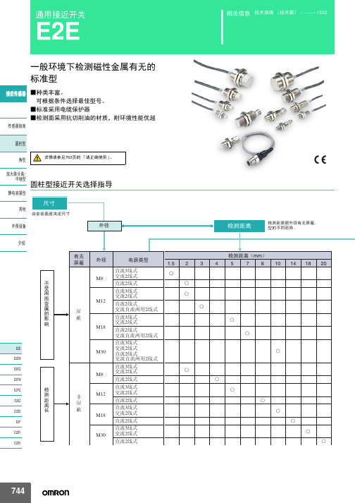
10mm 8mm
E2E-X10D1S-M1
D
——
—
E2E-X8MD1S-M1
D
——
—
M18
14mm
E2E-X14MD1S-M1
D
——
—
M30
20mm
E2E-X20MD1S-M1
D
——
—
M8
2mm
M12
ሣ㬑
M12 3mm
E2E-X2D1-M1G
A E2E-X2D2-M1G
D
E2E-X3D1-M1G *1
㾦ൟ
ᬒ఼ߚ行 Ё㒻ൟ
M30
10mm
无
M8
4mm
䴲ሣ㬑
M12
8mm
M18
14mm
E2E-X10D1-N E2E-X4MD1 E2E-X8MD1 E2E-X14MD1
*1*2*3 *2*3 *1*2*3 *1*2*3
E2E-X10D2-N E2E-X4MD2 E2E-X8MD2 E2E-X14MD2
ሣ㬑
1.5mm
E2E-X1R5E1-M3
M8 䴲ሣ㬑
M8 2mm
E2E-X2ME1-M3
输出形态PNP NO E2E-CR8B1 E2E-X1B1 E2E-C1B1 E2E-X1R5F1 E2E-X2F1 E2E-X5F1 E2E-X10F1 E2E-X2MF1 E2E-X5MF1 E2E-X10MF1 E2E-X18MF1
Ⳉ⌕2㒓ᓣ
ƻ ƻ
Ⳉ⌕3㒓ᓣ M18 Ѹ⌕2㒓ᓣ
Ⳉ⌕2㒓ᓣ
ƻ ƻ
Ⳉ⌕3㒓ᓣ M30 Ѹ⌕2㒓ᓣ
Ⳉ⌕2㒓ᓣ
ƻ ƻ
744
E2E
⬉⑤䕧ߎ Փ⫼⦃๗
倍加福接近传感器NCB4-12GM40-N0-V1电感式传感器
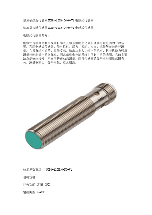
倍加福接近传感器NCB4-12GM40-N0-V1电感式传感器倍加福接近传感器NCB4-12GM40-N0-V1电感式传感器电感式传感器简介:电感式传感器是利用线圈自感或互感系数的变化来实现非电量电测的一种装置。
利用电感式传感器,能对位移、压力、振动、应变、流量等参数进行测量。
它具有结构简单、灵敏度高、输出功率大、输出阻抗小、抗干扰能力强及测量精度高等一系列优点,因此在机电控制系统中得到广泛的应用。
它的主要缺点是响应较慢,不宜于快速动态测量,而且传感器的分辨率与测量范围有关,测量范围大,分辨率低,反之则高。
技术参数节选 NCB4-12GM40-N0-V1通用规格开关功能常闭 (NC)输出类型 NAMUR额定工作距离 4 mm安装齐平确保操作距离 0 ... 3,24 mm实际工作距离 3,6 ... 4,4 mm 类型衰减系数 rAl 0,41衰减系数 rCu 0,39衰减系数 r304 0,78输出类型 2 线额定值额定电压 8,2 V (Ri 约 1 kΩ)开关频率 0 ... 1500 Hz迟滞 1 ... 15 类型 5 %反极性保护反极性保护短路保护是适用于 2:1 技术是,无需反极性保护二极管电流消耗未检测到测量板 min. 2,2 mA检测到测量板≤ 1 mA开关状态指示灯黄色多孔 LED功能性安全相关参数安全完整性级别 (SIL) SIL 2MTTFd 3010 a任务时间 (TM) 20 a诊断覆盖率 (DC) 0 %装置应用传感器作为采集和获取信息的工具,对系统的自动化检测和质量监测起着重要作用。
电感式传感器是一种互感式电感传感器,它可将微小的机械量,如位移、振动、压力造成的长度、内径、外径、不平行度、不垂直度、偏心、椭圆度等非电量物理量的几何变化转换为电信号的微小变化,转化为电参数进行测量,是一种灵敏度较高的传感器,具有结构简单可靠、输出功率大、抗阻抗能力强、对工作环境要求不高、稳定性好等一系列优点,因而被广泛应用于各种工程物理量检测与自动控制系统中 [3] 。
欧姆龙光电传感器原理及工作方式

传感器光电传感器概要光电传感器的定义「光电传感器」是利用光的各种性质,检测物体的有无和表面状态的变化等的传感器。
光电传感器主要由发光的投光部和接受光线的受光部构成。
如果投射的光线因检测物体不同而被遮掩或反射,到达受光部的量将会发生变化。
受光部将检测出这种变化,并转换为电气信号,进行输出。
大多使用可视光(主要为红色,也用绿色、蓝色来判断颜色)和红外光。
光电传感器如下图所示主要分为3类。
(详细内容请参见「分类」)对射型回归反射型扩散反射型光电传感器特长①检测距离长如果在对射型中保留10m以上的检测距离等,便能实现其他检测手段(磁性、超声波等)无法离检测。
达到的长距②对检测物体的限制少由于以检测物体引起的遮光和反射为检测原理,所以不象接近传感器等将检测物体限定在金属,它可对玻璃.塑料.木材.液体等几乎所有物体进行检测。
③响应时间短光本身为高速,并且传感器的电路都由电子零件构成,所以不包含机械性工作时间,响应时间非常短。
④分辨率高能通过高级设计技术使投光光束集中在小光点,或通过构成特殊的受光光学系统,来实现高分辨率。
也可进行微小物体的检测和高精度的位置检测。
⑤可实现非接触的检测可以无须机械性地接触检测物体实现检测,因此不会对检测物体和传感器造成损伤。
因此,传感器能长期使用。
⑥可实现颜色判别通过检测物体形成的光的反射率和吸收率根据被投光的光线波长和检测物体的颜色组合而有所差异。
利用这种性质,可对检测物体的颜色进行检测。
⑦便于调整在投射可视光的类型中,投光光束是眼睛可见的,便于对检测物体的位置进行调整。
光电传感器原理①光的性质直射光在空气中和水中时,总是直线传播。
使用对射型传感器外置的开叉来检测微小物体的示例便是运用了这种原理。
曲折是指光射入到曲折率不同的界面上时,通过该界面后,改变行进方向的现象。
反射(正反射、回归反射、扩散反射)在镜面和玻璃平面上,光会以与入射角相同的角度反射,称为正反射。
3个平面互相直角般组合的形状称为三面直角棱镜。
TCT40-16T3 16R3 超声波传感器 说明书

概述避障电路图超声波发射装置由NE555构成无稳多谐振荡器,其振荡频率由电阻W1、R1和C3决定通过调节W1可以改变振荡频率,输出的振荡信号经过CD4049的放大推动超声波换能器S1发声。
NE555的第4脚使能端可由单片机控制,当需要发射超声信号时该脚为高电平。
超声波接收装置超声波换能器S1接受到的微弱信号,经过交流耦合到IC1放大,其放大倍数为:A1=-R6/R4=-50;放大的信号在经过交流耦合到IC1的另一运放,其放大倍数为:A2=-R9/R7=-20;总增益为:A=A1*A2=1000。
经过放大的信号再由比较器LM311整形,输出标注TTL电平信号以被单片机接收。
测距电路I测距原理:超声波发射器向某一方向发射超声波,在发射时刻的同时开始计时,超声波在空气中传播,途中碰到障碍物就立即返回来,超声波接收器收到反射波就立即停止计时。
超声波在空气中的传播速度为340m/s,根据计时器记录的时间t,就可以计算出发射点距障碍物的距离(s),即:s=340t/21) 40kHz 脉冲的产生与超声波发射测距系统中的超声波传感器采用UCM40的压电陶瓷传感器,它的工作电压是40kHz的脉冲信号。
测距电路的输入端接单片机P1.0端口,单片机执行下面的程序后,在P1.0 端口输出一个40kHz的脉冲信号,经过三极管T放大,驱动超声波发射头UCM40T,发出40kHz的脉冲超声波,且持续发射200ms。
puzel: mov 14h, #12h; 超声波发射持续200mshere: cpl p1.0 ; 输出40kHz方波nop ;nop ;nop ;djnz 14h,here;ret2) 超声波的接收与处理接收头采用与发射头配对的UCM40R,将超声波调制脉冲变为交变电压信号,经运算放大器IC1A和IC1B两极放大后加至IC2。
IC2是带有锁定环的音频译码集成块LM567,内部的压控振荡器的中心频率f0=1/1.1R8C3,电容C4决定其锁定带宽。
nanomefos技术参数

nanomefos技术参数
nanomefos技术参数如下:
- CCD分辨率:像素1280x960。
- 测试模式:PSI+VSI检测模式。
- 纵向分辨率:小于0.1nm。
- RMS重复性:小于0.01nm,1σ。
- 台阶测量:准确度小于等于0.75%。
- 台阶高重复性小于等于0.1%,1σ。
- 高清晰无限远成像系统,白光高效LED,光谱滤光。
- Nikon干涉物镜配置2.5x,5x,10x,20x,50x。
- 200mm手动样品台(XY高精度)+倾斜±6°。
nanomefos分析及控制软件具有以下特点:
- 三维分析处理迅速,结果实时更新。
- 缩放、定位、平移、旋转等三维图像显示。
- 自主设定测量阈值,三维处理自动标注。
- 测量模式可根据需求自由切换。
- 可创建简单工作流程,简化重复工作。
- 三维图像支持高清打印。
- 可进行软件在线升级和远程支持服务。
此外,该设备的外形尺寸为800x490x480(mm),重量为130Kg,环境要求为温度24℃±2℃,湿度相对湿度10%—70%,无凝结,防震需要隔离1—120Hz的震动。
E+H超声波液位计探头FDU90_91_92_93_94_95
– FDU95: 45 m (148 ft):固体
– FDU96: 70 m (230 ft):固体
• 可在防爆危险区域中使用
优势
• 非接触式测量,降低了维护需求 • 内置温度传感器,用于行程 - 时间校正。即便温
度变化,也能准确测量 • 密封焊接 PVDF 传感器 FDU91/92 可以用于液体
过程条件 . . . . . . . . . . . . . . . . . . . . . . . . . . . . . . . . . . 15 过程温度与过程压力 . . . . . . . . . . . . . . . . . . . . . . . . . . . . . . . . 15
安装条件 . . . . . . . . . . . . . . . . . . . . . . . . . . . . . . . . . . 10 安装方式 ( 实例 ) . . . . . . . . . . . . . . . . . . . . . . . . . . . . . . . . . . . 10 物位测量时的安装条件 . . . . . . . . . . . . . . . . . . . . . . . . . . . . . . 11 流量测量时的安装条件 . . . . . . . . . . . . . . . . . . . . . . . . . . . . . . 12 使用 FAU80 松套法兰进行齐平安装 . . . . . . . . . . . . . . . . . . . . 13 使用安装短管安装 . . . . . . . . . . . . . . . . . . . . . . . . . . . . . . . . . . 14 在导波管中安装 . . . . . . . . . . . . . . . . . . . . . . . . . . . . . . . . . . . . 15
2018光电传感器----print
PC+ABS IP65
4
OS13 标准型、 通用性、 经济性、 无电位计 对射:10m 镜反:3m 漫反:0.4m
红光、 红外光
10-30VDC
NPN/PNP
PC+ABS
IP65
OS50 宽电压、 长距离、 继电器 对射:40m 镜反:10m 偏振镜反:6m 漫反:2.5m
红光、 红外光
24-240V AC/DC
L:亮态 D:暗态 C:亮态或暗态
接插件
Q1:接线端子 Q8:M8 4芯 Q8.3:M8 3芯 Q:M12 4芯 Q12.1:M12 5芯 Q12.8:M12 8芯 框内若无内容, 表示直接出线。
电压范围
5:12-240VDC/24-240VAC 6:10-30VDC
功能原理 O:光电传感器
检测距离
检测距离 光源
对射型
OP18-S6 (发射器) OP18-EVP6 (接收器) OP18-EVN6 (接收器) OP18-S6Q (发射器) OP18-EVP6Q (接收器) OP18-EVN6Q (接收器)
红外光
10m
——
——
红外光
10m
——
——
开关频率
—— 1000Hz 1000Hz —— 1000Hz 1000Hz
100 200 300 400 500 600 700 800 900 距离X(m)
距离Y(m)
距离Y(m)
距离Y(m)
距离Y(m)
40 30 20 10 0
0 -10 -20 -30 -40
OP18 镜反型特性曲线(OP18-RV)
0.5
1
1.5
2
2.5
U-GAGE 传感器 说明书
T30U 系列选型U -G A G E ®T30U 系列-既能模拟量输出,又能开关量输出的超声波传感器功能多样U-GAGE T30U 系列为超声传感器的多功能性设置了新标准:在同一个传感器中既包括开关量输出,又包括模拟量输出。
• 两种型号:NPN 或PNP 开关量输出,加上一个0 ~ 10V dc 或4 ~20mA 模拟量输出。
专利的超短“T ”型外壳T30U 为精巧、超短型的超声波传感器,检测头直径为30mm ,长度为竞争对手产品的一半。
• 四个LED 指示灯使您随时了解传感器的设置及工作状态• 红色LED 闪烁指示接收到的信号相对强度• 两个黄色LED 指示被测物位于检测窗口之间• T30U 数字滤波装置具有极强的抗干扰能力,并具有瞬时过压及反极性保护双开关量输出• 两个NPN 或两个PNP 开关量输出• 每路输出独立编程设定• 提供直接液位控制型号(泵入/泵出)按键编程设计,使调整更快、更容易、更安全T30U 可以简单地使用按钮在150mm - 1m (5.9” -39.4”) 或300mm - 2m (11.8” - 78.7” ) 范围内任意设定不同的检测窗口。
• 同竞争对手产品比较,T30U 设置过程更简便,只需三个步骤,即可完成设定。
• 用户还可以通过外部开关,计算机或控制器进行远程设定,更加方便、安全。
U-GAGE ®T30U 系列选型T30U 系列外形尺寸电缆式接插件式注:在电缆式产品型号后加W/30,电缆长度为9m ;接插件式产品需另购接插电缆† 技术参考资料请从 上下载T30U 系列选型U -G A G E ®U-GAGE ®T30U 系列选型–+NPNPNP* 4 - 20mA 或0 - 10V dc **最大100mA注:接线图同样适用于电缆式或QD 接插件式。
建议屏蔽线接地或电源负极T30U 系列接线图T30U系列波形图¶ˇ¶ˇ¶ˇ¶ˇU-GAGE T30U 有效波束,对于平板物体(典型)U-GAGE T30U 有效波束,对于柱形物体(典型)1米型2米型1米型2米型模拟量+开关量双开关量–+NPNPNPT30U 系列附件选型U -G A G E ®电缆:PVC 封套,聚氨酯镀铬黄铜连接螺母导线:20或22高柔性连接线,PVC 绝缘,镀金触点工作温度:-40°C ~ +90°C (-40°~ +194°F )电压等级:250V ac/300V dcT30U 系列选型U-GAGE®12.7 mm(0.50")Q45U 系列选型U -G A G E ®只需按一按键• 即可在100mm 到3000mm 检测距离间进行窗口设定• 微处理器控制的“示教”模式可以方便地设定检测窗口,只需将被测物置于检测位置第一设定点,点击一下按键,再将被测物置于检测位置第二设定点,点击按键即可。
杜邦传感器NCN4-12GM35-N0-V1产品说明书
12Releasedate:217-1-2415:34Dateofissue:217-1-2418113_eng.xml L+L-1 BN2 BUWire colors in accordance with EN 60947-5-6(brown)(blue)3R e l e a s e d a t e : 2017-01-24 15:34D a t e o f i s s u e : 2017-01-24181103_e n g .x m lInstructionManual electrical apparatus for hazardous areas Device category 1Gfor use in hazardous areas with gas, vapour and mist EC-T ype Examination CertificateCE marking ATEX marking ¬ II 1G Ex ia IIC T6…T1 G a The Ex-related marking can also be printed on the enclosed label.Standards EN 60079-0:2012+A11:2013 EN 60079-11:2012 Ignition protection "Intrinsic safety" Use is restricted to the following stated conditions Appropriate typeNCN4-12GM...-N0...Effective internal inductivity C i≤ 95 nF ; a cable length of 10 m is considered.Effective internal inductance L i ≤ 100 µH ; a cable length of 10 m is considered.G eneralThe apparatus has to be operated according to the appropriate data in the data sheet and in this instruction manual.The EU-type examination certificate has to be observed. The special conditions must be adhered to!The ATEX directive and therefore the EU-type examination certificates apply in gen-eral only to the use of electrical apparatus under atmospheric conditions.The use in ambient temperatures of > 60 °C was tested with regard to hot surfaces by the mentioned certification authority.If the equipment is not used under atmospheric conditions, a reduction of the permis-sible minimum ignition energies may have to be taken into consideration.Ambient temperatureDetails of the correlation between the type of circuit connected, the maximum per-missible ambient temperature, the temperature class, and the effective internal reac-tance values can be found on the EC-type examination certificate. Note: Use the temperature table for category 1 The 20 % reduction in accordance with EN 1127-1 has already been applied to the temperature table for category 1.Installation, commissioningLaws and/or regulations and standards governing the use or intended usage goal must be observed.The intrinsic safety is only assured in connection with an appropriate related appara-tus and according to the proof of intrinsic safety.The associated apparatus must satisfy the requirements of category ia.Due to the possible danger of ignition, which can arise due to faults and/or transient currents in the equipotential bonding system, galvanic isolation of the power supply and signal circuit is preferable. Associated apparatus without electrical isolation must only be used if the appropriate requirements of IEC 60079-14 are met. If the Ex-related marking is printed only on the supplied label, then this must be attached in the immediate vicinity of the sensor. The sticking surface for the label must be clean and free from grease. The attached label must be legible and indelible, including in the event of possible chemical corrosion.Maintenance No changes can be made to apparatus, which are operated in hazardous areas.Repairs to these apparatus are not possible.Special conditionsThe connecting parts of the sensor must be set up in such a way that degree of pro-tection IP20, in accordance with lEC 60529, is achieved as a minimum.Protection from mechanical dangerWhen using the device in a temperature range of -60 °C to -20 °C, protect the sensor against the effects of impact by installing an additional enclosure.The information regarding the minimum ambient temperature for the sensor as pro-vided in the datasheet must also be observed.Electrostatic chargeElectrostatic charges must be avoided on the mechanical housing components. Dangerous electrostatic charges on the mechanical housing components can be avoided by incorporating these in the equipotential bonding.4Releasedate:217-1-2415:34Dateofissue:217-1-2418113_eng.xml Instruction Manual electrical apparatus for hazardous areasDevice category 2G for use in hazardous areas with gas, vapour and mistEC-T ype Examination CertificateCE markingATEX marking ¬ II 1G Ex ia IIC T6…T1 G aThe Ex-significant identification is on the enclosed adhesive labelStandards EN 60079-0:2012+A11:2013 EN 60079-11:2012 Ignition protection "Intrinsic safety"Use is restricted to the following stated conditionsAppropriate type NCN4-12GM...-N0...Effective internal inductivity C i≤ 95 nF ; a cable length of 10 m is considered.Effective internal inductance L i≤ 100 µH ; a cable length of 10 m is considered.G eneral The apparatus has to be operated according to the appropriate data in the data sheetand in this instruction manual. The EU-type examination certificate has to beobserved. The special conditions must be adhered to!The ATEX directive and therefore the EU-type examination certificates apply in gen-eral only to the use of electrical apparatus under atmospheric conditions.The use in ambient temperatures of > 60 °C was tested with regard to hot surfacesby the mentioned certification authority.If the equipment is not used under atmospheric conditions, a reduction of the permis-sible minimum ignition energies may have to be taken into consideration.Maximum permissible ambient temperature T amb Details of the correlation between the type of circuit connected, the maximum per-missible ambient temperature, the temperature class, and the effective internal reac-tance values can be found on the EC-type examination certificate.Installation, commissioning Laws and/or regulations and standards governing the use or intended usage goalmust be observed. The intrinsic safety is only assured in connection with an appro-priate related apparatus and according to the proof of intrinsic safety.If the Ex-related marking is printed only on the supplied label, then this must beattached in the immediate vicinity of the sensor. The sticking surface for the labelmust be clean and free from grease. The attached label must be legible and indeli-ble, including in the event of possible chemical corrosion.Maintenance No changes can be made to apparatus, which are operated in hazardous areas.Repairs to these apparatus are not possible.Special conditions The connecting parts of the sensor must be set up in such a way that degree of pro-tection IP20, in accordance with lEC 60529, is achieved as a minimum.Protection from mechanical danger When using the device in a temperature range of -60 °C to -20 °C, protect the sensoragainst the effects of impact by installing an additional enclosure. The informationregarding the minimum ambient temperature for the sensor as provided in thedatasheet must also be observed.Electrostatic charge Electrostatic charges must be avoided on the mechanical housing components.Dangerous electrostatic charges on the mechanical housing components can beavoided by incorporating these in the equipotential bonding.5R e l e a s e d a t e : 2017-01-24 15:34D a t e o f i s s u e : 2017-01-24181103_e n g .x m lInstructionManual electrical apparatus for hazardous areas Device category 3G (ic) for use in hazardous areas with gas, vapour and mist CertificateCE marking ATEX marking ¬ II 3G Ex ic IIC T6…T1 GcThe Ex-significant identification is on the enclosed adhesive labelStandardsEN 60079-0:2012+A11:2013 EN 60079-11:2012 Ignition protection category "ic" Use is restricted to the following stated conditions Effective internal inductivity C i≤ 95 nF ; a cable length of 10 m is considered.Effective internal inductance L i≤ 100 µH ; A cable length of 10 m is considered.G eneralThe apparatus has to be operated according to the appropriate data in the data sheet and in this instruction manual. The data stated in the data sheet are restricted by this operating instruction!The special conditions must be observed!The ATEX Directive applies only to the use of apparatus under atmospheric condi-tions.If you use the device outside atmospheric conditions, consider that the permissible safety parameters should be reduced.Installation, commissioningLaws and/or regulations and standards governing the use or intended usage goal must be observed. The sensor must only be operated with energy-limited circuits, which satisfy the requirements of IEC 60079-11. The explosion group complies with the connected, supplying, power limiting circuit. If the Ex-relevant identification is printed exclusively on the adhesive label provided, this label must be affixed in the immediate vicinity of the sensor! The background surface to which the adhesivelabel is to be applied must be clean and free from grease! The applied label must be dura-ble and remain legible, with due consideration of the possibility of chemical corro-sion!Maintenance No changes can be made to apparatus, which are operated in hazardous areas.Repairs to these apparatus are not possible.Special conditionsfor Pi=34 mW, Ii=25 mA, T6 55 °C (131 °F) for Pi=34 mW, Ii=25 mA, T5 55 °C (131 °F) for Pi=34 mW, Ii=25 mA, T4-T1 55 °C (131 °F) for Pi=64 mW, Ii=25 mA, T6 55 °C (131 °F) for Pi=64 mW, Ii=25 mA, T5 55 °C (131 °F) for Pi=64 mW, Ii=25 mA, T4-T1 55 °C (131 °F) for Pi=169 mW, Ii=52 mA, T6 52 °C (125.6 °F) for Pi=169 mW, Ii=52 mA, T5 52 °C (125.6 °F) for Pi=169 mW, Ii=52 mA, T4-T1 52 °C (125.6 °F) for Pi=242 mW, Ii=76 mA, T6 44 °C (111.2 °F) for Pi=242 mW, Ii=76 mA, T5 44 °C (111.2 °F) for Pi=242 mW, Ii=76 mA, T4-T1 44 °C (111.2 °F)Protection from mechanical dangerThe sensor must not be mechanically damaged.When used in the temperature range below -20 °C the sensor should be protected from knocks by the provision of an additional housing.Electrostatic charge Electrostatic charges must be avoided on the mechanical housing components. Dangerous electrostatic charges on the mechanical housing components can be avoided by incorporating these in the equipotential bonding.Connection partsThe connection parts are to be installed, such that a minimum protection class of IP20 is achieved, in accordance with IEC 60529.6Releasedate:217-1-2415:34Dateofissue:217-1-2418113_eng.xml Instruction Manual electrical apparatus for hazardous areasDevice category 1D for use in hazardous areas with combustible dustEC-T ype Examination CertificateCE markingATEX marking ¬ II 1D Ex ia IIIC T135°C Da The Ex-related marking can also be printed on theenclosed label.Standards EN 60079-0:2012+A11:2013 EN 60079-11:2012 Ignition protection "Intrinsic safety"Use is restricted to the following stated conditionsAppropriate type NCN4-12GM...-N0...Effective internal inductivity C i≤ 95 nF ; a cable length of 10 m is considered.Effective internal inductance L i≤ 100 µH ; a cable length of 10 m is considered.G eneral The apparatus has to be operated according to the appropriate data in the data sheetand in this instruction manual.The EU-type examination certificate has to be observed.The ATEX directive and therefore the EU-type examination certificates apply in gen-eral only to the use of electrical apparatus under atmospheric conditions.The use in ambient temperatures of > 60 °C was tested with regard to hot surfacesby the mentioned certification authority.If the equipment is not used under atmospheric conditions, a reduction of the permis-sible minimum ignition energies may have to be taken into consideration.Maximum permissible ambient temperature T amb Details of the correlation between the type of circuit connected, the maximum per-missible ambient temperature, the surface temperature, and the effective internalreactance values can be found on the EC-type-examination certificate.The maximum permissible ambient temperature of the data sheet must benoted, in addition, the lower of the two values must be maintained. Installation, commissioning Laws and/or regulations and standards governing the use or intended usage goalmust be observed.The intrinsic safety is only assured in connection with an appropriate related appara-tus and according to the proof of intrinsic safety.If the Ex-related marking is printed only on the supplied label, then this must beattached in the immediate vicinity of the sensor. The sticking surface for the labelmust be clean and free from grease. The attached label must be legible and indeli-ble, including in the event of possible chemical corrosion.Maintenance No changes can be made to apparatus, which are operated in hazardous areas.Repairs to these apparatus are not possible.Special conditions The connecting parts of the sensor must be set up in such a way that degree of pro-tection IP20, in accordance with lEC 60529, is achieved as a minimum.Protection from mechanical danger When using the device in a temperature range of -60 °C to -20 °C, protect the sensoragainst the effects of impact by installing an additional enclosure. The informationregarding the minimum ambient temperature for the sensor as provided in thedatasheet must also be observed.Electrostatic charge Electrostatic charges must be avoided on the mechanical housing components.Dangerous electrostatic charges on the mechanical housing components can beavoided by incorporating these in the equipotential bonding.Do not attach the nameplate provided in areas where electrostatic charge can buildup.。