Controlled Low Strength Material 10
激光粒度仪-湿法处理

IntroductionParticle size analysis using wet dispersion is by far the mostwidespread method for obtaining reproducible results using laser diffraction. Wet analysis provides a method of dispersion for samples across a wide particle size range, ranging from sub-micron pigments through to sands and sediments. In the case of large particles orpolydisperse distributions the viscosity of wet dispersants ensures that bias-free measurements can be made, as the effects of particle sedimentation can be easily overcome. Dispersion can be readily achieved for diverse particulate systems due to the wide range of available wet dispersants available for laser diffraction measurements. The dispersion stability can also be optimized in a way that is not possible for drymeasurements. This is due to the fact that the dispersion energy available when particles are wetted in adispersant is much higher than that seen within a dry powder dispersion system. As such, wet analysis is often the only method available for thereproducible dispersion of sub-micron materials and is preferred for larger materials, especially in the case of sticky or strongly agglomeratedpowders. Particle friability is also not as much of an issue within wetanalysis, as the method of dispersion is less aggressive compared to dry analysis.Although it is possible to obtain good results using wet dispersion, this can only be achieved if the analyst first develops a robust method. Thisapplication note aims to provide users with an idea of the importantparameters that should be consideredas part of method development when defining a Standard OperatingProcedure (SOP) for measuring wet dispersions using laser diffraction. Laser diffraction measurements can appear to be easy to set up. However, it is important that the following factors associated with the sample are considered if realisticmeasurements are to be made: •Representative Sampling of the material under test, such that the sub-sample is characteristic of the whole batch.•Dispersant selection in terms of the type of liquid used to disperse the powder and any additives used to promote stabilization.Users must also configure theinstrument’s sample dispersion unit in order to achieve reproducible results that actually relate to the physical properties of the powder itself, either in terms of the agglomerated state or in a well-dispersed state. This requires control of the: •Measurement Settings and other analysis options, such as setting the correct obscuration.•Dispersion Energy in terms of the application of sonication to cause deagglomeration of the sample.Within this document it assumed that the user is familiar with the basicoperation of a laser diffraction system. This guidance document relates specifically to the Mastersizer 2000 system using the Hydro 2000S, Hydro 2000G or Hydro 2000MU wetdispersion units, all of which allow the user to sonicate the sample within the Mastersizer 2000 system and follow the dispersion process in real-time. However, the method development steps described here can be applied to the wet dispersion units used with other Malvern diffraction systems. Note that guidance on the selection of optical properties is given elsewhere.Representative SamplingThe way that the sample is withdrawn from the bulk material for analysis is one of the most important aspects of particle size analysis. This isparticularly true if large particles (>70 microns in size) are present in the sample. Laser diffraction is a volume-Wet method development for laserdiffraction measurementsTable 1: Dispersants for laser diffraction measurements.DispersantPolarity Water / Deionised Water Very Polar SolventOrganic Acids (e.g. Acetic Acid) Alcohols (e.g. Methanol / Ethanol / IsopropylAlcohol) Simple alkanes (Hexane / Heptane / Iso-Octane /Cyclohexane)Long-chain alkanes and alkenes (Dodecane /Mineral Oils / Sunflower Oil / Palm Oil)Very Non-Polar Solventbased measurement technique and is therefore sensitive to small changes in the amount of large material in the sample. This is because coarse particles occupy a large volume compared to smaller particles (one 100 micron particle has the same volume as one million 1 micron particles and will therefore give the same scattering response). A guide to how sampling can be controlled isgiven elsewhere [1]. If sampling is controlled it should be easy to obtain a measurement-to-measurementreproducibility within the limits defined in ISO13320-1[2], the ISO standard for laser diffraction measurements (within 3% at the D(v,0.5) and within 5% at the D(v,0.1) and D(v,0.9)). If sampling is not controlled then measurement-to-measurement variations of up to 20% can be observed.Dispersant selectionSelection of an appropriatedispersant is the next stage when making wet laser diffractionmeasurements. It is important that the chosen dispersant:Is transparent to the laser beam ,ensuring light scatteringmeasurements can be made. Has a different refractive index tothe particles being measured , as it is the refractive index difference which defines the intensity of scattering observed. Does not dissolve the materialunder test during the measurement. Can wet the particles beingmeasured, ensuring agglomerate dispersion. Can stabilize the particlesfollowing dispersion such that re-agglomeration does not occur. Is not too viscous as otherwisebubble formation may occur during measurements.Water is normally the first choice of solvent as it is transparent andinexpensive. For large particles it is possible to use normal tap water, although when setting SOPs the fact that tap water quality can vary between locations needs to be considered. Where possible,measurements should be made in deionised water, especially where there is a significant amount ofmaterial below 20µm in size, as the salts present in tap water can lead to particle agglomeration. It may also be necessary to add surfactants and other stabilizers to prevent agglomeration of fine particles. Many materials, especiallypharmaceuticals actives, are soluble in water. For such materials it will be necessary to use a less polardispersant (table 1). The choice of dispersant will in this case depend on the polarity of the material under test. The cost of disposal of some non-aqueous dispersants is also an important consideration.SurfactantsThe first stage of dispersion during a wet measurement is the wetting of the particle surface by the chosendispersant. In some cases it may be necessary to use a surfactant to cause wetting to occur. Surfactants (Surface Active Agents) work by lowering the surface tension of the dispersant. This reduces the contact angle between the dispersant and the particle surface, aiding dispersion. The choice of surfactant depends on the particle surface chemistry and the nature of the dispersant. Non-ionic surfactants (e.g. Tween 20 / 80; Span 20 / 80 ) are generally considered safe for use within pharmaceuticals or food applications. In someapplications anionic surfactants (e.g. SDS (sodium dodecylsulfate) or cationic surfactants (e.g. CTAB) can be used to not only improve wetting but also stabilize the particles byabsorbing to the particle surface, thus providing a barrier to agglomeration. A guide to different surfactants for useFigure 1: Cerium Oxide Suspensions containing different concentrations of Sodium Hexametaphosphate. In this case 0.1wt% represents the optimumconcentration for dispersion.0.0wt%0.01wt%0.05wt% 0.1wt%0.2wt%0.5wt% 1.0wt% 5.0wt%with different particle and dispersanttypes can found in ISO14887[3].In all cases the concentration of surfactant should be carefullycontrolled. Surfactants are active at very low concentrations (>0.001 g/l). Generally 1-2 drops of a diluted surfactant solution (10%concentration) is sufficient to improve particle wetting. Using higherconcentrations can lead to bubble formation within the dispersion unit, causing the reporting of large particles that are not present in the sample.StabilizersOnce the particles are dispersed within the chosen dispersant it is important to ensure that re-agglomeration is prevented. Within aqueous dispersants controlling the conductivity of the suspension can ensure stability. This can simply involve using deionised water as a dispersant rather than tap water. It is also possible to use charge-stabilizing agents such as SodiumHexametaphosphate (Calgon), Ammonium Citrate or Sodium Pyrophosphate. Each of theseincreases the stability of a suspensionby increasing the zeta-potential (this is related to the particle charge). However, just as with surfactants, adding too much of these stabilizing agents can cause dispersionproblems. Typically the concentration of these species should not be higher than 1w/v% otherwise the conductivity of the solution will be too high, causing agglomeration to occur. A good example of dispersionoptimization using these stabilizers isgiven elsewhere [4].Optimizing Dispersant SelectionIt is possible to choose the correct dispersion conditions without the need for carrying out particle sizemeasurements. The sample under test can be dispersed in a series of vials containing different dispersants. If the particles float on the top of the dispersant this suggests that wetting is poor – this can be improved byeither adding surfactants or by moving to a dispersant with a lower surface tension. If the particles are wetted by the dispersant then the user should sonicate the sample and then observe the settling behaviour. An example of this is shown in figure 1, wheresodium hexametaphosphate has been used to stabilize a cerium oxide suspension. As can be seen, at low concentrations the suspension is unstable and has completely settled out. Between 0.01wt% and 0.5wt% the suspension is stable – this suggests that a concentration of around 0.25wt% would provide a robust means of ensuring dispersion stability. Finally, the suspension becomes unstable when the concentration of sodiumhexametaphosphate is increased beyond 0.5wt%. This is due to theincrease in the solution ionic strength.Measurement SettingsDuring SOP development, it isimportant to consider how the amount of sample and the dispersion unit settings affect the measured particle size.Pump and Stirrer SettingsOptimization of the pump / stirrer rate can be simply be achieved bydetermining how the reported particle size changes as the pump speed is increased. An example of this is shown in figure 2. At low speeds the reported particle size is too low as the pump rate is not fast enough tosuspend the large particles within the sample. At higher pump rates (1500 – 3000 rpm) the reported particle size reaches a plateau value where the particle size remains constant. It is at this point that the particles are correctly presented to themeasurement cell. The pump rate should be set at a value at the centre of this range (i.e. at around 2250 rpm for this example). Note that users should not default to using the fastest possible pump rate as this may lead to bubble formation in somedispersants. High pump speeds can also cause particle break-up, especially for emulsion samples.050010001500200025003000Pump Rate / rpm204060P a r t i c l e S i z e / M i c r o n sFigure 2: Particle size as a function of pump/stirrer rate.Sample ConcentrationThe sample concentration used for wet laser diffraction measurements must be set so as to allow reproducible scattering data to be obtained without observing multiple scattering [2]. For fine particle measurements (<10 microns in size) this will require users to measure at no more than 10% obscuration. For coarser materials measurement obscurations of up to 20% can be used in order to maximize the single-to-nose ratio. The concentration at which multiple scattering occurs can be assessed by measuring the particle size of a stable dispersion as a function of the measurement obscuration. At low obscurations the reported particle size will be constant – this is where the correct result is obtained. The reported size will shift towards the finer particle sizes at higher obscurations as multiple scattering starts to occur. Sonication EnergyOnce the material being measured has been wetted by the chosen dispersant it is important to ensure that full particle dispersion is achieved. ISO13320-1 providesguidance concerning the process bywhich the state of dispersion can beoptimized. It suggests that users mustunderstand how the input ofdispersion energy affects the particlesize. For wet measurements thisinvolves determining how thedispersion is affected by theapplication of ultrasound.Solid Particle MeasurementsThe process of wet methoddevelopment for the measurement ofsolid particles is as follows:1. The particle size of the sampleshould be measured followinginitial wetting of the particles.2. The particle size should bemeasured during the applicationof ultrasound. This allows thedispersion of the sample to beunderstood.3. The ultrasound probe should beswitched off and the particle sizemonitored to ensure that thedispersion is stable.A theoretical plot of how the particlesize may vary during dispersion isgiven in figure 3. Following initialwetting of the sample in thedispersion unit the particle size mayslowly decrease – this is due to thedispersion of loosely boundagglomerates under the action of thepump and stirrer. If the obscurationreduces rapidly at this point it maysuggest that the material under test issoluble in the chosen dispersant. Ifthis is case the obscuration drop willoften be associated with an increasein the measured particle size, as thefines present in the sample will bedissolved most rapidly. If this isobserved a different dispersant shouldbe used.Following the initial stage ofdispersion, ultrasound should beapplied and the particle size followedin real-time. Rapid dispersion isnormally observed at this stage asstrongly bound agglomerates aredispersed. As the time of sonication isincreased the particle size shouldreach a plateau where the particlesize becomes stable – this representsthe fully dispersed state. If the particlesize continues to reduce over timethis may suggest that particle break-up occurs during sonication.Sonication may also causeagglomeration to occur – this wouldsuggest that the dispersion isunstable, requiring the analyst toadjust the dispersion conditions.Finally, the particle size should bemonitored with the ultrasound probeswitched off once full dispersion isachieved. If the particle size remainsstable when this occurs then thedispersion conditions are optimized. Ifthe particle size increases thedispersion conditions will need to beadjusted, for example by moving tohigher stabilizer concentrations or byusing deionised water rather than tapwater. Note that it is also possible tomake measurements undercontinuous sonication in order toprevent re-agglomeration.Figure 3: Theoretical plot showing the process of particle dispersion.Emulsion MeasurementsThe dilution of emulsions for laser diffraction measurements can lead to particle coalescence if the dispersion conditions are not optimized. If possible, the choice of surfactants and stabilizers should mimic those present in the product being tested. If the composition of the emulsion is unknown then measurements should be made in deionised water buffered with non-ionic surfactant. Dispersion stability should be assessed by making repeat measurements over time. Sonication should never be used for emulsion samples, as this will cause further emulsification. High pump and stirrer rates should also be avoided as high shear can cause droplet break-up.Method Development ExamplesThe following examples show how the dispersion of materials can be optimized following the guidance given above.SilicaFigure 4 shows the dispersion process for a silica catalyst support material. Initially the particle size was measured during dispersion under the action of the pump and stirrer within the dispersion unit. As can be seen, the coarse particle fraction (Dv90) reduces during this process, as loose agglomerates are dispersed. Following this the ultrasound probe within the dispersion unit was switched on, causing further rapid dispersion. This continued until a stable particle size was obtained. The fact that the particle size stabilized shows that full dispersion was achieved without particle break-up (the size would continue to reduce if break-up occurred). At this point the ultrasound was switched off in order to assess if the dispersion was stable. In this case the particle size remained constant, showing that the dispersion is indeed stable.05101520Measurement Number50100150200250Size/MicronsFigure 4: Particle size distribution statistics obtained during the dispersion of asilica catalyst support material.0306090120150180210240Sonication Time / sec2468Size/MicronsFigure 5: Particle size distribution statistics obtained during the dispersion of apharmaceutical powder.Pharmaceutical PowderA similar dispersion process can be observed for other materials. Figure 5 shows how the particle size varies with sonication time for apharmaceutical powder. In this case the powder was dispersed inIsopropyl Alcohol, as it was found to be soluble in water. Sonication of the sample showed an initial decrease in the particle size until a plateau was reached at between 120sec and 240sec of sonication. In this case a sonication time of 180sec was chosen as a robust way of dispersing the powder. Table 2 shows the batch-to-batch variation in the results obtained using an SOP set for this sonication time, confirming that this provides a reproducible dispersion method.Emulsion MeasurementsThe importance of setting the correct dispersion conditions for emulsion measurements is shown in figure 5. Here the Dv50 reported for a series of food emulsion measurements isshown for two different dispersants. In each case the dispersion medium was buffered with a low concentration of non-ionic surfactant. However, oneset of measurements was carried outin tap water that contained a high concentration of electrolytes whereas the other measurements were carriedout in deionised water. As can be seen, the high electrolyte concentration in the tap water causedthe emulsion to flocculate, leading tothe reporting of a much larger particlesize than expected. Moving todeionised water allowed stablemeasurements to be achieved.Note that in this case making singlemeasurements would not haveallowed the dispersion process to beunderstood. Both dispersion methodsyielded a similar particle size at thestart of the measurement process.Only by making repeat measurementcan the dispersion process followed,revealing the instability of the dispersion when using tap water as a dispersant. This then allows apossible source of result variability to be understood and isolated.SummaryThe development of a wetmeasurement method requires the user to explore and understand the way in which the material is sampled, the choice of dispersant and how the sample reacts to the application of ultrasound. By controlling each of these a robust method can bedeveloped, ensuring good batch-to-batch reproducibility. This, in turn, increases the sensitivity of the size measurement to changes in the material properties.Table 2: Results obtained for different pharmaceutical powder batches.Measurement Dv10 / Microns Dv50 / Microns Dv90 / Microns1 1.86 3.13 5.412 1.87 3.13 5.413 1.87 3.14 5.44 4 1.85 3.12 5.405 1.90 3.16 5.29 Average 1.87 3.13 5.39 Variation (%) 0.97 0.45 1.10 0246810Measurement Number0.10.20.30.40.5D v 50 / M i c r o n sFigure 5: Dv50 reported for emulsion measurements in deionised water and tapwater.References[1] Sampling for Particle SizeAnalysis. Malvern Application Note:MRK456.[2] ISO13320 (1999). Particle SizeAnalysis - Laser Diffraction Methods.Part 1: General Principles.[3] ISO14887 (2000). SamplePreparation – Dispersing proceduresfor powders in liquids.[4] The use of zeta potentialmeasurements for improvingdispersion during particle sizedetermination. Malvern ApplicationNote: MRK373.Malvern Instruments LtdEnigma Business Park • Grovewood Road • Malvern • Worcestershire • UK • WR14 1XZTel: +44 (0)1684 892456 • Fax: +44 (0)1684 892789Malvern Instruments WorldwideSales and service centers in over 50 countries for details visit /contactmore information at 。
高三英语材料科学单选题60题
高三英语材料科学单选题60题1.Metal is a common material in engineering. Which of the following is not a metal?A.ironB.aluminumC.glassD.copper答案:C。
本题考查材料科学中金属的概念。
铁(iron)、铝(aluminum)和铜((copper)都是常见的金属。
而玻璃((glass)是一种非金属材料,主要由硅酸盐等组成。
2.Which material is often used for insulation?A.steelB.plasticC.goldD.silver答案:B。
在材料科学中,塑料((plastic)常被用作绝缘材料。
钢(steel)、金((gold)和银((silver)都是导电性能较好的金属材料,不适合用于绝缘。
3.In the field of materials science, which one is a composite material?A.woodB.paperC.concreteD.water答案:C。
混凝土((concrete)是一种复合材料,由水泥、骨料和水等组成。
木头((wood)是天然材料。
纸((paper)主要由纤维素等组成,不是复合材料。
水(water)是一种化合物,不是复合材料。
4.Which material is known for its high hardness?A.rubberB.leatherC.diamondD.cloth答案:C。
在材料科学中,钻石((diamond)以其高硬度而闻名。
橡胶(rubber)、皮革(leather)和布(cloth)的硬度都较低。
5.Which of the following materials is ductile?A.brickB.glassC.copperD.stone答案:C。
在材料科学中,铜((copper)是一种具有延展性((ductile)的金属材料。
PA10T材料物性表

P ROVISIONAL D ATA S HEETG RIVORY HTG RIVORY XE 4027BLACK 9916Product descriptionGrivory XE 4027 black 9916 is a 30% glass-fibre reinforced flame retardant (UL 94 V-0) engineering thermoplastic material based on a semicrystalline, partially aromatic co-polyamide.Grivory XE 4027 black 9916 is free of halogens and red phosphorus.RoHS: Grivory XE 4027 black 9916 is in compliance with RoHS (2002/95/EC, Re-striction of Hazardous Substances). WEEE:Parts produced from Grivory XE 4027 black 9916 are not subject to "selec-tive treatment" according the Directive 2002/96/EC on Waste Electrical and Elec-tronic Equipment.ISO polymer designation: PA 10T/XASTM designation: PPA, polyphthalamide The main distinguishing features of Grivory HT-PPA, when compared to other poly-amides, are its good performance at high temperatures providing parts which are stiffer, stronger, have better heat distortion and dimensional stability as well as excel-lent chemical resistance and low moisture absorption.Grivory XE 4027 black 9916 is especially suitable for injection moulded components in electrical and electronic applications which require a flame class acc. UL 94 V-0. The material is suitable for lead-free SMT reflow soldering acc. i.e. JEDEC J-STD-020C (peak temperature 260°C). Compo-nents conforming to JEDEC MSL1 are achievable.PROPERTIESMechanical Properties Standard Unit State Grivory XE 4027black 9916Tensile E-modulus 1 mm/min ISO 527 MPa drycond.10'00010'000Tensile strength at break 5 mm/min ISO 527 MPa drycond.115110Elongation at break 5 mm/min ISO 527 % drycond.1.51.5Impact strength Charpy, 23°C ISO 179/2-1eU kJ/m2drycond.3535Impact strength Charpy, -30°C ISO 179/2-1eU kJ/m2drycond.3535Notched impact strength Charpy, 23°C ISO 1792-/1eA kJ/m2drycond.66Notched impact strength Charpy, -30°C ISO 179/2-1eA kJ/m2cond. 6Ball indentation hardness ISO 2039-1 MPa drycond.225225Thermal PropertiesMelting point DSC ISO 11357 °C dry 295 Heat deflection temperature HDT/A 1.80 MPa ISO 75 °C dry 265 Heat deflection temperature HDT/C 8.00 MPa ISO 75 °C dry 175 Thermal expansion coefficient long. 23-55°C ISO 11359 10-4/K dry 0.2 Thermal expansion coefficient trans. 23-55°C ISO 11359 10-4/K dry 0.65 Maximum usage temperature long term ISO 2578 °C dry 150Electrical PropertiesDielectric strength IEC 60243-1 kV/mmdrycond.3333Comparative tracking index CTI IEC 60112 - cond. 600Specific volume resistivity IEC 60093 Ω · m drycond.109109Specific surface resistivity IEC 60093 Ωcond. 1011General PropertiesDensity ISO 1183 g/cm3 dry 1.41 Flammability (UL 94) 0.4 - 3.2 mm ISO 1210 rating - V-0IEC GWFI IEC 60695-2-12 °C - 960 Glow wire temperature (3mm)IEC GWIT IEC 60695-2-13 °C 775 Water absorption 23°C/saturated ISO 62 % - 1.5 Moisture absorption 23°C/50% r.h. ISO 62 % - 0.6 Linear mould shrinkage long. ISO 294 % dry 0.3 Linear mould shrinkage trans. ISO 294 % dry 1.0 Product nomenclature acc. ISO 1874: PA 10T/X, MHF, 11-100, GF30Information on Injection Moulding ofGrivory XE 4027 black 9916This technical data sheet for Grivory XE 4027 black 9916 provides you with useful information on material preparation, machine requirements, tooling and processing.MATERIAL PREPARATIONGrivory XE 4027 black 9916 is delivered dry and ready for processing in sealed packaging. Pre-drying is not necessary.StorageSealed, undamaged bags can be kept over a long period of time in storage facilities which are dry, protected from the influence of weather and where the bags can be protected from damage.Handling and SafetyDetailed information can be obtained from the material safety data sheet (MSDS) which can be requested with every material order.Drying During its manufacturing process Grivory XE 4027 black 9916 is dried and packed with a moisturecontent of ≤ 0.10%. Should the packaging become damaged or the material is left open too long, then the material must be dried. A too high moisture content can be shown by a foaming melt and silver streaks on the moulded part. The drying can be done as follows:Temperature max. 80°CTime 4 - 12 hoursDew point -40°CTemperature max. 100°CTime 4 - 12 hoursDrying time If there is only little evidence of foaming of the melt or just slight silver streaks on the part, then the above mentioned minimal drying time will be suffi-cient. Material, which is stored open over days shows strong foaming, unusually easy flowing, streaks and rough surface on the moulded part. Then the maximal drying time is required.Silver streaks can also be caused by overheating of the material (over 350°C) or by too long melt residence time in the barrel.Drying temperaturePolyamides are affected by oxidation at tempera-tures above 80°C in the presence of oxygen. Visible yellowing of the material is an indication of oxida-tion. Hence temperatures above 80°C for desiccant dryers and temperatures above 100°C for vacuum ovens should be avoided. In order to detect oxida-tion it is advised to keep a small amount of granu-late (light colour only !) as a comparison sample.At longer residence times (over 1 hour) a hopper dryer (80°C) is useful.Use of RegrindGrivory XE 4027 black 9916 is a thermoplastic material. This allows recycling of sprues, runners and rejected components in the running processIt is recommended to add a maximum of 25% re-grind as long as the requirements on the final part allow the addition of regrind.To ensure a trouble free processing, special pre-caution has to be taken by the moulder. Followingpoints have to be kept in mind: • Avoid moisture absorption of the regrind (oth-erwise drying is necessary)Contamination by foreign material such as other polymers, dust or oil has to be avoided Property and colour changes of the part can be controlled with proper handling measures. MACHINE REQUIREMENTSGrivory XE 4027 black 9916 can be processed eco-nomically on all injection moulding machines suit-able for polyamides. Screw Wear and corrosion protected, 3-zone universal screws with check valves are recommended.Length 18 D - 22 D Compression ratio 2 - 2.5Screw Desiccant dryer Vacuum ovenShot VolumeThe metering stroke must be longer than the length of the check valve (without decompression dis-tance).Shot volume = 0.5 - 0.8 x (max. shot volume)HeatingAt least three separately controllable heating zones, able of reaching cylinder temperatures up to 350°C are required. A separate nozzle heating is necessary. The cylinder flange temperature must be controllable (cooling).NozzleOpen nozzles are simple, allow an easy melt flow and are long lasting. There is, however, the danger that during retraction of the screw after injection, air maybe drawn into the barrel (decompression). For this reason, needle shut-off nozzles are often used.Clamping ForceAs a rule of thumb the clamping force can be esti-mated using the following formula:TOOLINGThe design of the mould tool should follow the general rules for glass fibre reinforced thermo-plastics.For the mould cavities common mould tool steel quality (e.g. hardened steel) which has been hard-ened to level of 56 - 65 HRC is necessary. We recommend additional wear protection in areas of high flow rates in the tool (e.g. pin point gates, hot runner nozzles).Demoulding / Draft AngleParts moulded from Grivory HT are setting very quickly showing excellent dimensional stability. Asymmetric demoulding and undercuts are to be avoided. It is favourable to foresee high numbers of large ejector pins or a stripper plate. Demoulding draft angles between 1 to 5° are acceptable. The following values can be considered:(VDI 3400) 12 1518 21 24 27 Depth of roughness (µm) 0.4 0.6 0.8 1.1 1.6 2.2 Demoulding angle (%) 11 1.1 1.2 1.3 1.5(VDI 3400) 30 33 36 39 42 45 Depth of roughness (µm) 3.2 4.5 6.3 9 13 18 Demoulding angle (%) 1.822.5345VentingIn order to prevent burn marks and to improve the weld line strength, proper venting of the mould cav-ity should be provided. Venting channels on the parting surface with dimensions of depth 0.02 mm and width 2 - 5 mm are recommended.Gate and RunnerTo achieve an optimal mould-fill and to avoid sink marks, a central gate at the thickest section of the moulding is recommended. Pin point gate (direct) or tunnel gates are more economical and more com-mon with technical moulding.To avoid premature solidification of the melt and difficult mould filling, the following points should be considered:0.8 x thickest wall section of the injectionmoulding part1.4 x thickest wall section of the injection moulding part (but minimum 4 mm)PROCESSINGMould Filling, Post Pressure and DosingThe best surface finish and a high weld line strength are achieved with a high injection speed and when a sufficiently long post pressure is em-ployed.The injection speed should be chosen to be re-duced towards the end of the filling process in order to avoid overheating and burning. For dosing at low screw speed and pressure the cooling time should be fully utilised.Selecting the injection unit Gate diameterRunner diameterBasic Machine SettingsIn order to start up the machines for processing Grivory XE 4027 black 9916, following basic set-tings can be recommended:Flange 80°CZone 1 305 - 320°CZone 2 305 - 320°CZone 3 305 - 320°CNozzle 305 - 320°CTool 110 - 150°CMelt 300 - 330°CInjection speed medium - highHold-on pressure (spec.) 500 - 800 barDynamic pressure (hydr.) 5 - 15 barPeripheral screw speed 0.1 - 0.3 m/s Start-up and PurgingForeign materials in the cylinder should be removed with suitable purging materials. Hot-runner systems should be purged likewise. Glass fibre reinforced polyamide 66 is a suitable “bridging material”. Cylinder heating should start with a clean, product-free screw, starting from the temperature level of the “bridging material” of 300°C up to the required temperature level of 300-330°C (see processing data).After at least three full dosings (free-shots) - apply-ing the shortest possible residence time - the start up procedure can be implemented.After completion of production with Grivory HT the screw, cylinder and melt distribution system should be cleaned out thoroughly.ConditioningThe dimensions and the mechanical properties of Grivory HT products are only marginally influenced by moisture absorption. For testing purposes, parts can be stored in a climatic chamber until an in-crease in weight of 1 % has been achieved. In order to avoid stress through swelling, conditioning in hot water is to be avoided. CUSTOMER SERVICESEMS-GRIVORY is a specialist for polyamide syn-thesis and polyamide processing. Our customer services are not only concerned with the manufac-turing and supply of engineering thermoplastics but also provide a full of technical support program: • Rheological design calculation / FEA• Prototype tooling• Material selection• Processing support• Mould and component designWe are happy to advise you. Simply call one of our sales offices.The recommendations and data given are based on our experience to date, however, no liability can be assumed in connection with their usage and processing.Generated / updated: SEK / 07.2008This version replaces all previous product specific data sheets.Temperatures Speeds / Pressures。
Chapter 1 Basic Concepts of RC Structures

The Cubic Compressive Strength f cu (1)Definition: In GB50010-2002,the grade of
concrete is rated by the compressive strength of a
cubic specimen with side length of 150 mm, cured for 28 days under standard curing conditions(temperature is at 20℃±2℃,humidity is over 95%), tested by standard test method
Disadvantages: (1)high self-weight solution Light aggregate material
(2)Crack resistance is, work with cracks solution Prestressed concrete (3)Construction is impacted by climate conditions, the a
st = 1.2 10–5
concrete ct = 1.0 ~ 1.5 10–5 (3) Steel rebar embedded in concrete, which can prevent steel from rust.
3、 The main advantages and disadvantages of RC structures
Example: a span of 4m, a concentrated load at midspan of tested beam, beam section size is 200 ×300mm, concrete is C20. Please see:
纳米技术

Ferroelectric selfassembled PbTiO3 perovskite nanostructures onto (100) SrTiO3 substrates from a novel microemulsion aided sol–gel preparation method M L Calzada et al 2007 Nanotechnology 18 375603
Morphology and oxide shell structure of iron nanoparticles grown by sputtergas aggregation C M Wang et al 2007 Nanotechnology 18 255603
Laser-induced assembly of gold nanoparticles into colloidal crystals N Harris et al 2007 Nanotechnology 18 365301
Nanotechnology
Advanced Manufacturing Technology
Definition
Systems for transforming matter, energy, and information, based on nanometer-scale components with preciselnanotechnology has also been used more broadly to refer to techniques that produce or measure features less than 100 nanometers in size.
Concrete aggregates
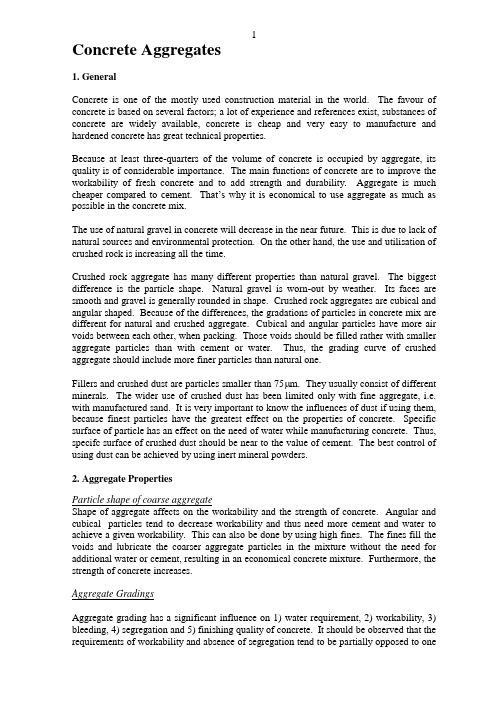
1Concrete Aggregates1. GeneralConcrete is one of the mostly used construction material in the world. The favour of concrete is based on several factors; a lot of experience and references exist, substances of concrete are widely available, concrete is cheap and very easy to manufacture and hardened concrete has great technical properties.Because at least three-quarters of the volume of concrete is occupied by aggregate, its quality is of considerable importance. The main functions of concrete are to improve the workability of fresh concrete and to add strength and durability. Aggregate is much cheaper compared to cement. That’s why it is economical to use aggregate as much as possible in the concrete mix.The use of natural gravel in concrete will decrease in the near future. This is due to lack of natural sources and environmental protection. On the other hand, the use and utilisation of crushed rock is increasing all the time.Crushed rock aggregate has many different properties than natural gravel. The biggest difference is the particle shape. Natural gravel is worn-out by weather. Its faces are smooth and gravel is generally rounded in shape. Crushed rock aggregates are cubical and angular shaped. Because of the differences, the gradations of particles in concrete mix are different for natural and crushed aggregate. Cubical and angular particles have more air voids between each other, when packing. Those voids should be filled rather with smaller aggregate particles than with cement or water. Thus, the grading curve of crushed aggregate should include more finer particles than natural one.Fillers and crushed dust are particles smaller than 75 m. They usually consist of different minerals. The wider use of crushed dust has been limited only with fine aggregate, i.e. with manufactured sand. It is very important to know the influences of dust if using them, because finest particles have the greatest effect on the properties of concrete. Specific surface of particle has an effect on the need of water while manufacturing concrete. Thus, specifc surface of crushed dust should be near to the value of cement. The best control of using dust can be achieved by using inert mineral powders.2. Aggregate PropertiesParticle shape of coarse aggregateShape of aggregate affects on the workability and the strength of concrete. Angular and cubical particles tend to decrease workability and thus need more cement and water to achieve a given workability. This can also be done by using high fines. The fines fill the voids and lubricate the coarser aggregate particles in the mixture without the need for additional water or cement, resulting in an economical concrete mixture. Furthermore, the strength of concrete increases.Aggregate GradingsAggregate grading has a significant influence on 1) water requirement, 2) workability, 3) bleeding, 4) segregation and 5) finishing quality of concrete. It should be observed that the requirements of workability and absence of segregation tend to be partially opposed to one2another. The easier it is for the particles of different size to pack, smaller particles passing into the voids between the larger ones, the easier it is also for the small particles to be shaken out of the voids, i.e. to segregate in the dry state.The actual grading requirements depend, to some extent, on the shape and surface characteristics of the particles. For instance, sharp, angular particles with rough surfaces should have slightly finer grading in order to reduce the possibility of interlocking and to compensate for the high friction between the particles. The actual grading of crushed aggregate is affected primarily by the type of crushing plant employed [33]. This means, that the grading curves should be different for crushed and natural aggregates.Although there are many effects of grading of aggregate on the properties of concrete, nothing else matters as much as the constant particle distribution. When grading remains constant through the concrete structure, the amounts of water and cement can be controlled. In the cases where grading varies, cement content must be over estimated. Constant and varying particle distribution is demonstrated in .Quality of Crushed DustThe mineral composition and surface texture are the most important properties of fillers. Shape and size of fillers are also important features. Specific surfaces vary more between minerals than between rock types. It should be noted that different minerals have different influence on the properties of concrete. For example, quartz, k-feldspar and plagioclase have lower specific surfaces compared to olivine, serpentine and hornblende. The needed amount of water depends on the specific surfaces of particles. The use of minerals with high specific surface should be avoided, because more water is needed to cover all the surfaces of particles. Table 1 showns specific surfaces of some minerals, cement and mineral by-products.Surfaces of minerals should be clean, i.e. minerals should not consist any deleterious substances. For instance, some natural fillers may consist of ferro accumulation, clay and organic dust. These substances multiple the surface texture of fillers and thus increase the need of water. Beside previous, they may also come off the surface of the fillers and thus decrease the strength of concrete.3Standards all over the world limit the wider use of very fine aggregate (minus 0,075 mm). This is mainly due to fact, that natural sand have been used as concrete aggregate. Natural, minus 0,075 mm material is usually clay or otherwise harmful material in concrete, so the value for minus 0,075mm is usually limited to very low level.Strength of AggregateIn order to durable concrete, the strength of aggregate has to be greater than of concrete. However, high strength aggregate is not always available. That kind of aggregate can be used only in a concrete of low strength. This is, for instance, the case with laterite, a material widely spread in Africa, South Asia and South America, which can rarely produce concrete stronger than 10 MPa.Table pressive strength of American rocks commonly used as concrete aggregate.Porosity and Absorption of AggregateThe porosity and absorption of aggregate, influence such properties of aggregate as the bond between it and the hydrated cement paste, the resistance of concrete to freezing and thawing, moisture content of aggregate, as well as its chemical stability and resistance to abrasion.Water absorptionWater absorption is an indirect measure of the permeability of an aggregate that, in turn, can relate to other physical characteristics such as mechanical strength, shrinkage, soundness and to its general durability potential. In general, less absorptive aggregate often tends to be more resistant to mechanical forces and to weathering [7].It may be noted that gravel has generally a higher absorption than crushed rock of the same petrologic character because weathering results in the outer layer of the gravel particles being more porous and absorbent [33].Moisture Content of AggregateAggregate exposed to rain collects a considerable amount of moisture on the surface of the particles and may keep this moisture over long periods. Coarse aggregate rarely contains more than 1 per cent of surface moisture but fine aggregate can contain in excess of 10 per cent. The great amount of water, as moisture, should be taken account when designing the concrete mixes. This ”extra” water may cause remarkable increase of water content and thus the increase of water/cement ratioSoundness of AggregateThis is the term used to describe the ability of aggregate to resist excessive changes in volume as a result of changes in physical conditions. Lack of soundness is thus distinct from expansion caused by the chemical reactions between the aggregate and the alkalis in cement.Unsoundness is exhibited by porous flints and cherts, by some shales, by limestones with expansive clay and by other particles containing clay minerals. For instance, an altered dolerite has been found to change in dimension by as much as 600 x 10-6 with wetting and drying. Concrete containing this aggregate might fail under unfavourable conditions.Alkali-Silica ReactionIn recent years, an increasing number of deleterious chemical reactions between the aggregate and the surrounding cement paste has been observed. The most common reaction is between the active silica constituents of the aggregate and the alkalis in cement. The reactive forms of silica are opal, chalcedony and tridymite. These reactive materials occur in opline or chalcedonic cherts, in siliceous limestones, in rhyolites and rhyolitic tuffs and in phyllites.The reaction starts with the attack on the siliceous minerals in the aggregate by the alkaline hydroxides in pore water derived from the alkalis in the cement. As a result, an alkali-silicate gel is formed, either in planes of weakness or pores in the aggregate. In the latter case, a characteristic altered surface zone is formed. This may destroy the bond between the aggregate and the surrounding hydrated cement paste.The alkali-silica reaction occurs only in the presence of water. Thus, drying out the concrete and prevention of future contact with water is an effective means of stopping the reaction. A higher temperature accelerates the progress of reaction but does not increase the total expansion induced by the reaction.Alkali-Carbonate ReactionAnother type of deleterious aggregate reaction is that between some dolomite limestone aggregates and the alkalis in cement. The volume of the products of this reaction is smaller than the volume of the original materials. So, this reaction is quite different from alkali-silica reaction. It is likely that the gel that is formed is subject to swelling in a manner similar to swelling clays. Thus, under humid conditions, expansion of concrete takes place. Typically, reaction zones up to 2 mm are formed around the active aggregate particles. Cracking develops within these rims and leads to a network of cracks and a loss of bond between the aggregate and the cement paste.Thermal Properties of AggregateCoefficient of thermal expansionThe coefficient of thermal expansion of aggregate influences the value of such a coefficient of concrete containing the given aggregate: the higher the coefficient of the aggregate the higher the coefficient the concrete. This is, however, depending on the aggregate content in the mix.It has been suggested that if the coefficients of thermal expansion of the coarse aggregate and of the hydrated cement paste differ too much, a large change in temperature may introduce differential movement. This can cause break in the bonds between the aggregate particles and the surroundings paste. A large difference between the coefficients is not necessarily detrimental when the temperature does not vary the range of 4 to 60 o C. Nevertheless, when the two coefficients differ by more than 5.5 x 10⁻⁶ per o C the durability of concrete subjected to freezing and thawing may be threatened.For hydrated cement paste, the coefficient varies between 11...16 x 10 -6per o C. The coefficients of different rock types range between 1…16 x 10 -6 per o C.If extreme temperatures are expected, the detailed properties of any given aggregate have to be known. For instance, quartz undergoes inversion at 574 o C and expands suddenly by 0.85 per cent. This would disrupt the concrete and for this reason fire-resistant concrete is never made with quartz aggregate.Specific heatSpecific heat represents the heat capacity of concrete. It is little affected by the mineralogical character of the aggregate, but is considerably increased by an increase in moisture content of aggregate. Specific heat increases with an increase in temperature and with a decrease in the density of the concrete. The common range of values for ordinary concrete varies between 840 and 1170 J/kg per o C. Specific heat is needed when fire resistance of concrete is estimated.ConductivityThis measures the ability of the material to conduct heat and is defined as the ratio of the flux of heat to temperature gradient. Thermal conductivity is measured in joules per second per square metre of area of body when the temperature difference is 1 o C per metre of thickness of the body.3. Recycling of ConcreteThe use of recycled materials, like concrete and brick, will increse as a construsction material all over the world. This is due to two factors; natural sources are declined and free land for dumping sites are no more available. These problems are reality in dense populated areas, for example in Japan and Central Europe.Recyled concrete has many benefical properties. However, crushed concrete has to be free of deleterious constituents like plastic and lumber. If crushed concrete is grinded near to the size of cement, the crushed concrete can be used in low strength concrete in secondary structures replacing cement. Because of a weak hydraulic property of grinded concrete, it is suitable for land structures and for the bases of highways.。
ASTM G160-03(2009)用实验室土壤囊评估非金属材料微生物敏感性的标准实施规程
Designation:G160–03(Reapproved2009)Standard Practice forEvaluating Microbial Susceptibility of Nonmetallic Materials By Laboratory Soil Burial1This standard is issued under thefixed designation G160;the number immediately following the designation indicates the year of original adoption or,in the case of revision,the year of last revision.A number in parentheses indicates the year of last reapproval.A superscript epsilon(´)indicates an editorial change since the last revision or reapproval.1.Scope1.1This practice is limited to the method of conducting an evaluation of a nonmetallic material’s microbiological suscep-tibility when in contact with the natural environment of the soil.This practice is intended for use on solid material test specimens that are no larger than approximately2cm(3⁄4in.) thick and100cm2(20in.2)or onfilm forming materials such as coatings which may be tested in the form offilms at least50 by50mm(2by2in.)in size.This practice may be applied to articles that do not spend the majority of their service life in soil.1.2A wide variety of properties may be affected by micro-bial attack depending on material or item characteristics. Standard methods(where available)should be used for each different property to be evaluated.This practice does not attempt to enumerate all of the possible properties of interest nor specify the most appropriate test for those properties.Test methods must,however,be appropriate to the material being tested.1.3It is recommended that this practice be combined with appropriate environmental exposures(for example,sunlight simulating weathering devices,the hydrolytic effects of ex-tended aqueous contact,or extraneous nutrients)or fabrication into articles(for example,adhesive bonding of seams)which may promote microbiological susceptibility during the service life of the material.1.4The values stated in SI units are to be regarded as standard.The values given in parentheses are provided for information purposes only.1.5This standard does not purport to address all of the safety concerns,if any,associated with its use.It is the responsibility of the user of this standard to establish appro-priate safety and health practices and determine the applica-bility of regulatory limitations prior to use.2.Significance and Use2.1These results may be used to compare the susceptibility of materials when exposed to this test procedure.2.2Microbiological susceptibility may be reflected by a number of changes including staining,weight loss,or reduction in tensile orflexural strength.2.3This practice may be considered an inoculation with a mixed culture of fungi and bacteria.3.Soil3.1Composition—Soil shall be composed of equal parts of fertile topsoil(soil with a high clay content should not be used),well-rotted and shredded horse manure,and coarse sand (10to40mesh).3.2Mixing—The soil composition of3.1should be pre-pared by simple mixing and sifting through1⁄4-in.mesh screen.3.3Aging—The mixture is aged for three months and resifted twice at four-week intervals during the three months. After three months,a viability control of untreated cotton cloth, 400to475g/m2(12to14oz/yd2),buried in the soil shall have a tensile strength loss of at least50%afterfive days.N OTE1—The soil mixture may be used for sequential tests as long as the cotton cloth control degrades within the specified time period.3.4pH—The soil shall have a pH between 6.5to7.5, checked periodically,and maintained by the addition of ground limestone to raise the pH orflowers of sulfur to lower the pH. The soil pH may be taken by dispersing1weight part soil in20 parts of water,shaking or stirring,then allowing the mix to settle for1h.The pH is measured with indicator paper, electrodes,or by titration.3.5Moisture—The soil shall be maintained at between20 and30%moisture,based on the dry weight of the soil.(The percent moisture is calculated by weighing approximately50 mL of a representative portion and taking the portion to constant weight by placing the soil in an oven at a temperature of101to106°C.)Water lost during use as a result of1This practice is under the jurisdiction of Committee G03on Weathering andDurability and is the direct responsibility of Subcommittee G03.04on BiologicalDeterioration.Current edition approved June1,2009.Published July2009.Originally approvedst previous edition approved in2003as G160–03.DOI:10.1520/G0160-03R09.1Copyright.©ASTM International,100Barr Harbor Drive PO box C-700West Conshohocken,Pennsylvania19428-2959,United Statesevaporation shall be replaced without deforming the soil bed.If the surrounding atmosphere is maintained at 85to 95%relative humidity,this loss is negligible,however,the moisture level should be periodically measured.4.Apparatus4.1Soil Container —The container shall be any material of suitable mechanical strength and chemical/microbial resistance and,if porous,shall be lined with impermeable material.It shall be of any size that is convenient to handle and having a depth of at least 12.7cm (5in.).4.2External Environment —An apparatus capable of main-taining a temperature of 3062°C (8663.6°F)and a relative humidity to 85to 95%,into which the assembled container is inserted,is necessary.An incubator or controlled tropical chamber is adequate.5.Test Specimens5.1Completely fabricated parts or sections cut from fabri-cated parts may be used as test specimens.The simplest specimen may be a 50-by 50-mm (2-by 2-in.)piece,a 50-mm (2-in.)diameter piece,or a piece (rod or tubing)at least 76mm (3in.)long cut from the material to be tested.5.2Film-forming materials such as coatings may be tested in the form of films at least 50by 50mm (2by 2in.)in size.Such films may be prepared by casting on glass and stripping after cure or by impregnating (completely covering)filter paper or ignited glass fabric.5.3For visual evaluation,a minimum of three test speci-mens shall be used.5.4In devising a test program intended to reveal quantita-tive changes occurring during and after exposure,an adequate number of specimens should be evaluated to establish a valid value for the original property.For example,if five replicate test specimens are required to establish a tensile strength of a film material,at least that number of test specimens shall be removed and tested for each exposure period.It is to be expected that values of physical or mechanical properties at various stages of fungal attack will be variable.The ASTM Manual 72may be used as a guide.6.Viability6.1The viability must be recommended as in 3.3concurrent with the test specimen and exposed consistent with the test specimen duration and number of test specimens.7.Replicates7.1A minimum of four replicates are recommended.8.Duration8.1The exposure period for soil burial,unless otherwise specified,shall be for a minimum of 60days.N OTE 2—The test specimens cannot be removed for the soil bed,once they have been buried,until the exposure period has been completed.Disturbing the soil bed in such a manner as removing the test specimensmay affect the growth of soil microbes and thus cause inconsistent results.A separate set of specimens must be used for each exposure interval (for example,a set of replicates for 30,60,and 90days as needed).9.Calculation and Interpretation of Results9.1Visual —At the end of the exposure period,the speci-mens shall be removed from the soil bed and conditioned according to methods appropriate to the material being tested.For visual evaluation,the material is rinsed under a stream of tap water while gently rubbing between fingers to remove soil and air-drying at 20°C (68°F)for minimum amount of time.Alternatively,the material may be gently vacuumed or very gently air-brushed.9.2Microbial staining shall be evaluated as follows:Observed Growth or StainRating None0Trace (less than 10%coverage)1Light (10to 30%coverage)2Moderate (30to 60%coverage)3Heavy (60%to complete coverage)49.3Property Changes —Physical and mechanical changes such as tensile strength,flexibility,weight loss,or other tests,may be performed as described in appropriate ASTM or other test methods.Tests shall be conducted on unexposed and exposed specimens for the purpose of comparison in determin-ing the extent of microbial degradation of the test material.9.4Calculate the change in property for each replicate specimen using one of the following equations:C e ,i 5X e ,i 2X o (1)C e ,i 5X e ,i 2X f(2)where:X e,i =measured property of each exposed specimen,X o =mean of property from initial measurements onunexposed specimens,andX f =mean of property from measurements on file speci-mens.9.5Use the following equation to determine the mean change in property:C 5(i 51nC e ,in(3)where:n =number or exposed specimens.9.6Use the following equation to determine the standard deviation of the change in property:n(4)S c 5Œ(~C i 2C !2n 2110.Report10.1Report the following information:age of bed,speci-men size,number of replicates,performance of viability control,visual staining in accordance with 9.1and 9.2or property change in accordance with 9.3,duration of burial,and any specific measurements requested.2Manual on Presentation of Data and Control Chart Analysis ,6th ed.,Manual 7,American Society for Testing and Materials,1990.210.2Satisfactory or unsatisfactory performance of a mate-rial is dependent on the applicable standard for that material or methods agreed upon between the investigators.11.Precision and Bias11.1A precision and bias statement cannot be made at this time.12.Keywords12.1biodegradeable;biological deterioration;defacement; disfigurement;fungal resistance;fungi;laboratory soil culture; microbial susceptibility;microbiological deterioration;mil-dew;mixed microbial innoculum;mold growth;soil environmentASTM International takes no position respecting the validity of any patent rights asserted in connection with any item mentioned in this ers of this standard are expressly advised that determination of the validity of any such patent rights,and the risk of infringement of such rights,are entirely their own responsibility.This standard is subject to revision at any time by the responsible technical committee and must be reviewed everyfive years and if not revised,either reapproved or withdrawn.Your comments are invited either for revision of this standard or for additional standards and should be addressed to ASTM International Headquarters.Your comments will receive careful consideration at a meeting of the responsible technical committee,which you may attend.If you feel that your comments have not received a fair hearing you should make your views known to the ASTM Committee on Standards,at the address shown below.This standard is copyrighted by ASTM International,100Barr Harbor Drive,PO Box C700,West Conshohocken,PA19428-2959, United States.Individual reprints(single or multiple copies)of this standard may be obtained by contacting ASTM at the above address or at610-832-9585(phone),610-832-9555(fax),or service@(e-mail);or through the ASTM website().3。
PCB培训胶片二_英文版
Back
LAMINATION
COPPER FOIL
INNER LAYERS
PRE-PREG
Back
LAMINATION
Back
DRILLING
Back
DRILLING
Back
DRILLING
DRILLING
• Design Standards:
IPC – 2221 – For rigid boards. IPC – 2223 – For flex & rigid flex boards.
Pad to Drill Ratio
• Pad size definition rule:
- Pad size = drill size + Annular ring * 2 + minimum standard Fabrication allowance.
PLASMA/ PERMANGANAT
ELECTROLESS COPPEபைடு நூலகம் PLATING
DRY FILM LAMINATION
AFTER IMAGING
DEVELOPING
COPPER PLATING (ELECTROPLATING)
TIN PLATING (ELECTROPLATING)
Basic Design Rules
Layer >
Via Hole Diameter
. -. "
Layer > . - . "
Layer > . - . "
Via Hole Depth
冶金学词汇
Liquidmetalcorrosion
熔盐腐蚀
Fusedsaltcorrosion
全面腐蚀
Generalcorrosion
均匀腐蚀
Uniformcorrosion
局部腐蚀
Localizedcorrosion
点蚀
Pittingcorrosion
缝隙腐蚀
Crevicecorrosion
晶间腐蚀
Intergranularcorrosion
刀口腐蚀
Knife-linecorrosion
丝状腐蚀
Folifomcorrosion
剥蚀
Exfoliationcorrosion
贫合金元素腐蚀
dealloying
脱锌
dezincification
应力腐蚀
Stresscorrosion
腐蚀疲乏
Corrosionfatigue
极图
Polefigure
反极图
Inversepolefigure
硫印
Sulfurprint
无损检测
Non-destructivetesting
超声检测
Ultrasonictesting
磁粉检测
Magnetic-particletesting
X射线探伤
X-rayradiographicinspection
断口形貌学
fractography
杯锥断口
Cup-onefractuure
丝状断口
Silkyfractuure
纤维状断口
Fibrousfractuure
层状断口
Laminationfractuure
贝壳状断口
铝合金英文文献
Aluminium alloyAluminium alloys are alloys in which aluminium (Al) is the predominant metal. The typical alloying elements are copper,magnesium, manganese, silicon and zinc. There are two principal classifications, namely casting alloys and wrought alloys, both of which are further subdivided into the categories heat-treatable and non-heat-treatable. About 85% of aluminium is used for wrought products, for example rolled plate, foils and extrusions. Cast aluminium alloys yield cost effective products due to the low melting point, although they generally have lower tensile strengths than wrought alloys. The most important cast aluminium alloy system is Al-Si, where the high levels of silicon (4.0% to 13%) contribute to give good casting characteristics. Aluminium alloys are widely used in engineering structures and components where light weight or corrosion resistance is required.[1]Aluminium alloy compositions are registered with The Aluminum Association. Many organizations publish more specific standards for the manufacture of aluminium alloy, including the Society of Automotive Engineers standards organization, specifically its aerospace standards subgroups,[3] and ASTM International.Engineering usesomewhat-higher tensile strengths than the commonly used kinds of steel, simply replacing a steel part with an aluminium alloy might lead to problems.With completely new metal products, the design choices are often governed by the choice of manufacturing technology. Extrusions are particularly important in this regard, owing to the ease with which aluminium alloys, particularly the Al-Mg-Si series, can be extruded to form complex profiles.In general, stiffer and lighter designs can be achieved with aluminium alloys than is feasible with steels. For instance, consider the bending of a thin-walled tube: the second moment of area is inversely related to the stress in the tube wall, i.e. stresses are lower for larger values. The second moment of area is proportional to the cube of the radius times t he wall thickness, thus increasing the radius (and weight) by 26% will lead to a halving of the wall stress. For this reason, bicycle frames made of aluminium alloys make use of larger tube diameters than steel or titanium in order to yield the desired stiffness and strength. In automotive engineering, cars made of aluminium alloys employ space frames made of extruded profiles to ensure rigidity. This represents a radical change from the common approach for current steel car design, which depend on the body shells for stiffness, that is a unibody design.Aluminium alloys are widely used in automotive engines, particularly in cylinderblocks and crankcases due to the weight savings that are possible. Since aluminium alloys are susceptible to warping at elevated temperatures, the cooling system of such engines is critical. Manufacturing techniques and metallurgical advancements have also been instrumental for the successful application in automotive engines. In the 1960s, the aluminium cylinderheads of the Corvair earned a reputation for failure and stripping of threads, which is not seen in current aluminium cylinder heads.An important structural limitation of aluminium alloys is their lower fatigue strength compared to steel. In controlled laboratory conditions, steels display a fatigue limit, which is the stress amplitude below which no failures occur - the metal does not continue to weaken with extended stress cycles. Aluminum alloys do not have this lower fatigue limit and will continue to weaken with continued stress cycles. Aluminium alloys are therefore sparsely used in parts that require high fatigue strength in the high cycle regime (more than 107 stress cycles). Heat sensitivity considerationsOften, the metal's sensitivity to heat must also be considered. Even a relatively routine workshop procedure involving heating is complicated by the fact that aluminium, unlike steel, will melt without first glowing red. Forming operations where a blow torch is used therefore require some expertise, because no visual signs reveal how close the material is to melting.Aluminium also is subject to internal stresses and strains when it is overheated; the tendency of the metal to creep under these stresses tends to result in delayed distortions. For example, the warping or cracking of overheated aluminium automobile cylinder heads is commonly observed, sometimes years later, as is the tendency of welded aluminium bicycle frames to gradually twist out of alignment from the stresses of the welding process. Thus, the aerospace industry avoids heat altogether by joining parts with adhesives or mechanical fasteners. Adhesive bonding was used in some bicycle frames in the 1970s, with unfortunate results when the aluminium tubing corroded slightly, loosening the adhesive and collapsing the frame.Stresses in overheated aluminium can be relieved by heat-treating the parts in an oven and gradually cooling it—in effect annealing the stresses. Yet these parts may still become distorted, so that heat-treating of welded bicycle frames, for instance, can result in a significant fraction becoming misaligned. If the misalignment is not too severe, the cooled parts may be bent into alignment. Of course, if the frame is properly designed for rigidity (see above), that bending will require enormous force.Aluminium's intolerance to high temperatures has not precluded its use in rocketry; even for use in constructing combustion chambers where gases can reach 3500 K. The Agena upper stage engine used a regeneratively cooled aluminium design for some parts of the nozzle, including the thermally critical throat region; in fact the extremely high thermal conductivity of aluminium prevented the throat from reaching the melting point even under massive heat flux, resulting in a reliable lightweight component.Household wiringMain article: Aluminium wireBecause of its high conductivity and relatively low price compared with copper in the 1960s, aluminium was introduced at that time for household electrical wiring in North America, even though many fixtures had not been designed to accept aluminium wire. But the new use brought some problems:∙The greater coefficient of thermal expansion of aluminium causes the wire to expand and contract relative to the dissimilar metal screw connection, eventually loosening the connection.∙Pure aluminium has a tendency to "creep" under steady sustained pressure (to a greater degree as the temperature rises), again loosening the connection.∙Galvanic corrosion from the dissimilar metals increases the electrical resistance of the connection.All of this resulted in overheated and loose connections, and this in turn resulted in some fires. Builders then became wary of using the wire, and many jurisdictions outlawed its use in very small sizes, in new construction. Yet newer fixtures eventually were introduced with connections designed to avoid loosening and overheating. At first they were marked "Al/Cu", but they now bear a "CO/ALR" coding.Another way to forestall the heating problem is to crimp the aluminium wire to a short "pigtail" of copper wire. A properly done high-pressure crimp by the proper tool is tight enough to reduce any thermal expansion of the aluminium. Today, new alloys, designs, and methods are used for aluminium wiring in combination with aluminium terminations.Wrought alloysThe International Alloy Designation System is the most widely accepted naming schemefor wrought alloys. Each alloy is given a four-digit number, where the first digit indicates the major alloying elements.∙1000 series are essentially pure aluminium with a minimum 99% aluminium content by weight and can be work hardened.∙2000 series are alloyed with copper, can be precipitation hardened to strengths comparable to steel. Formerly referred to as duralumin, they were once the most common aerospace alloys, but were susceptible to stress corrosion cracking and are increasingly replaced by 7000 series in new designs.∙3000 series are alloyed with manganese, and can be work hardened.∙4000 series are alloyed with silicon. They are also known as silumin.∙5000 series are alloyed with magnesium.∙6000 series are alloyed with magnesium and silicon, are easy to machine, and can be precipitation hardened, but not to the high strengths that 2000 and 7000 can reach.∙7000 series are alloyed with zinc, and can be precipitation hardened to the highest strengths of any aluminium alloy.∙8000 series is a category mainly used for lithium alloys.[citation needed]Cast alloysThe Aluminum Association (AA) has adopted a nomenclature similar to that of wrought alloys. British Standard and DIN have different designations. In the AA system, the second two digits reveal the minimum percentage of aluminium, e.g. 150.x correspond to a minimum of 99.50% aluminium. The digit after the decimal point takes a value of 0 or 1, denoting casting and ingot respectively.[1] The main alloying elements in the AA system are as follows:[citation needed]∙1xx.x series are minimum 99% aluminium∙2xx.x series copper∙3xx.x series silicon, copper and/or magnesium∙4xx.x series silicon∙5xx.x series magnesium∙7xx.x series zinc∙8xx.x series lithiumAerospace alloysScandium-AluminiumParts of the Mig–29 are made from Al-Sc alloy.[9]The addition of scandium to aluminium creates nanoscale Al3Sc precipitates which limit the excessive grain growth that occurs in the heat-affected zone of welded aluminium components. This has two beneficial effects: the precipitated Al3Sc forms smaller crystals than are formed in other aluminium alloys[9] and the width of precipitate-free zones that normally exist at the grain boundaries of age-hardenenable aluminium alloys is reduced.[9] Scandium is also a potent grain refiner in cast aluminium alloys, and atom for atom, the most potent strengthener in aluminium, both as a result of grain refinement and precipitation strengthening.However, titanium alloys, which are stronger but heavier, are cheaper and much more widely used.[10]4043, 5183, 6005A, 6082 also used in marine constructions and off shore applications. Cycling alloysThese alloys are used for cycling frames and components[citation needed]。
- 1、下载文档前请自行甄别文档内容的完整性,平台不提供额外的编辑、内容补充、找答案等附加服务。
- 2、"仅部分预览"的文档,不可在线预览部分如存在完整性等问题,可反馈申请退款(可完整预览的文档不适用该条件!)。
- 3、如文档侵犯您的权益,请联系客服反馈,我们会尽快为您处理(人工客服工作时间:9:00-18:30)。
Performance of industrial by-products in controlledlow-strength materials (CLSM)M.C.Nataraja *,Y.NalandaSri Jayachamarajendra College of Engineering,Mysore 570006,IndiaAccepted 19March 2007Available online 19June 2007AbstractAs the construction industry continues to recognise the importance of sustainable development,technologies such as controlled low-strength material (CLSM)have come to the forefront as viable means of safely and efficiently using by-product and waste materials in infrastructure applications.CLSM,also known as flowable fill,can be defined as an engineered backfill material containing fine aggre-gates,Portland cement,water and a by-product material.CLSM can provide an economically and technically feasible alternative to con-ventional fill materials because of potential cost savings related to its unique and often superior technical properties.In this present experimental study,three industrial by-products,namely fly ash (FA),rice husk ash (RHA)and quarry dust (QD),were used as constit-uent materials in CLSM.Mixture proportions were developed for CLSM containing these industrial by-products and were tested in the laboratory for various properties,such as flowability,unconfined compressive strength (UCS),stress–strain behaviour,density,water absorption and volume parison between the two pozzolanic materials,namely FA and RHA,for their potential to produce an effective CLSM has been made.It can be observed from the results that by-product materials such as FA,RHA and QD can be suc-cessfully used in CLSM.This successful utilization of by-product materials is important to sustainable development and is the focus of this research.Ó2007Elsevier Ltd.All rights reserved.1.IntroductionControlled low-strength materials (CLSM)are self-compacting,low-strength,cementitious materials used primarily as backfill,void fill and utility bedding in place of conventional compacted fill.CLSM is an effective and practical alternative to commonly used compacted earth backfills.CLSM has the unique properties of a high-strength soil and a low-strength cementitious material.As defined by American Concrete Institute (ACI)Committee 229,CLSM is a self-compacting cementitious material that is in a flowable state at the time of placement and has a specified compressive strength of 8.3MPa or less at the age of 28days (ACI 229,1999).CLSM flows like a liquid,sets like a solid,is self-levelling,and requires no compac-tion or vibration to achieve maximum density and the desired strength.The use of CLSM has gained increasing acceptance by the construction industry as a flowable,self-compacting backfill.CLSM is characterized by very high workability,low density and low strength,which allow for self-compaction.It exhibits very little settlement and has bearing capacity greater than that provided by native soil.Several terms are currently used to describe CLSM,such as flowable fill,unshrinkable fill,controlled density fill,lean-mix backfill,lean concrete backfill,flowable mortar,flow-crete,lean concrete slurry,plastic soil–cement,soil–cement slurry and K-Krete.Terms such as foamed concrete and cellular concrete are typically used to refer to CLSM used in roof and floor toppings and insulating applications.By-product materials such as fly ash (FA),ground granu-lated blast furnace slag (GGBFS),and waste foundry sand are usually employed in flowable fill mixtures in order to reduce the cost and to ensure low maximum compressive0956-053X/$-see front matter Ó2007Elsevier Ltd.All rights reserved.doi:10.1016/j.wasman.2007.03.030*Corresponding author.Tel.:+9108212343521;fax:+9108212515770.E-mail address:nataraja96@ (M.C.Nataraja)/locate/wasmanAvailable online at Waste Management 28(2008)1168–1181strengths(Naik et al.,2001,2006).Non-standard materials may be used to produce CLSM as long as the materials have been tested and found to satisfy the intended applica-tion.As the mechanical properties of hardened CLSM are inferior to those of concrete,large amounts offines must be used in the production of CLSM.With this,required and much improved properties of the fresh mix can be ensured.The use of CLSM is increasing in India in the recent days.Significant research activities are in progress at vari-ous institutions.After observing the various research works in India and abroad,the present investigation on the performance of FA,rice husk ash(RHA)and quarry dust(QD)in CLSM has been made.2.Literature reviewCLSM provides the engineer and constructor with another tool to help solve the many challenges of construct-ing and maintaining today’s civil infrastructure.Although CLSM generally costs more per cubic meter than most soil or granular backfill materials,its many advantages such as reduced labour,self-levelling capability and versatility often result in lower in-place costs(Ramme,1997).The benefits and applications of CLSM were imparted efficiently in the successful completion of the Boston harbour tunnel project. The underground utility corridors,space between slurry walls and the terrain werefilled with CLSM to ensure properfilling and to achieve maximum compaction.Void fill is another common application of CLSM products. Using CLSM for voidfill has proven to be very economical in many cases.CLSM could be placed at a rate of approx-imately60m3/h,at least six times faster than placement of conventional backfill(Sullivan,1997).The Colorado Department of Transportation(CDOT)(USA)has con-verted four bridge structures to on-grade roadways using CLSM to backfill culverts placed beneath the existing struc-ture.This method has resulted in substantial cost savings, faster design time and quicker construction ing CLSM to convert an existing bridge to a culvert instead of replacing the bridge has reduced the construction time by about2months(Goldbaum et al.,1997).Previous researchers have evaluated the use of various industrial by-products in the production of CLSM.Some of the waste materials that are being used in CLSM are FA,bottom ash,blast furnace slag,foundry sand,pulver-ised rubber tires,cement kiln dust(CKD),andflue gas des-ulfurisation(FGD)materials(Naik et al.,2003,2006; Pierce et al.,2003;Pierce and Blackwell,2003).CLSM offers a direct means to utilise a wide range of industrial by-products,which otherwise pose a problem in their safe disposal.Many FGD materials have low unit weight and good shear strength characteristics and thus hold promise for flowablefill applications.The unconfined compressive strength(UCS)test results showed that FGDflowablefill gains sufficient strength for variousflowablefill applica-tions(Butalia et al.,2001).The low mechanical require-ments(compared with structural concrete)enable the use of industrial by-products for the production of CLSM. Large values of compressive strength,up to6MPa,were obtained at later ages(90days)when materials that may have pozzolanic or cementing properties were used(Katz and Kovler,2004).Increasing the cement content reduced shrinkage and the tendency to crack;while increasing the fine content significantly increased the shrinkage(Katz and Kovler,2004).Only a fewfine cracks were detected in the base mixtures containingfly ash or asphalt dust.Crumb rubber from scrap tires can be used to produce a high quality,lightweightflowablefill because of its low spe-cific gravity.Reasonableflowability,improved ductility and higher thermal insulation were achieved using crumb rub-ber inflowablefill,when compared to standardflowablefill (Pierce and Blackwell,2003).The low-strength property of CKD can be advantageous when used in CLSM because most applications require future excavatability.Theflow-ability and setting times within24h could be achieved with most mixtures.CKD can be beneficially added to produce a very low-strength material due to the smaller amount of lime and silica present in CKD,which offers comparable strengths to soils used for conventionalfills and many other low-strength applications(Pierce et al.,2003).Wider cracks were observed in the CKD mixture exhibiting somewhat larger shrinkage(Katz and Kovler,2004).Cement by-pass dust can also be utilised in theflowable fill mixtures.The strength of the mixtures varies quite sig-nificantly because of the considerable difference in the amount of water added to reach the required slump. According to Taha et al.(2004),the quantities of materials used in each mixture also influence the strength and slump values.Foundry sand is becoming a more viable product for use in CLSM because of its lower cost and increasing availability.By-product foundry sand used in CLSM pro-vides better properties compared to that of CLSM contain-ing crushed limestone sand(Tikalsky et al.,2000).It also assisted in keeping the strength from exceeding the desired upper limit of700kPa.Spent casting sand can be used as a constituent in CLSM.The uniform size of the spent casting sand can provide goodflowability,and its lower cost enhances its economic advantage as a constituent in CLSM (Tikalsky et al.,1998).Constituent materials and quantities will have an effect on water demand and compressive strength of CLSM. Substituting foundry sand for concrete sand in similar mix-tures reduced the compressive strength from 3.49to 0.25MPa at91days,because of higher water demands (Du et al.,2002).Prolonged mixing and retempering will have its influence on most of the properties of CLSM. Extending the mixing time beyond30min does not signifi-cantly alterflowability or bleeding but decreases unconfined compressive strength and delays the time of setting.Retem-pering CLSM with20%extra water increasesflowability but reduces measured strengths at28days and90days, depending on mixing time.Retempering does not signifi-cantly impact the material in itsfluid state(GassmanM.C.Nataraja,Y.Nalanda/Waste Management28(2008)1168–11811169et al.,2001).Nagaraj et al.(2006)analysed theflow behav-iour of CLSM slurries.In their investigation,they consid-ered the binary combination of cement and FA as the cementing material for the analysis offlow behaviour.They observed that theflow behaviour of controlled low-strength materials follows a pattern in accordance with Lyse rule. According to Nmai et al.(1997),CLSM can be classified as either regular or low density,depending on the density. Mixtures that have a density of800kg/m3or more are gen-erally classified as regular CLSM(Reg-CLSM),and those with a density less than that are classified as low-density CLSM(LD-CLSM).Regular CLSM consists of cement, FA,fine aggregate,water and/or air-entraining admixtures, whereas LD-CLSM consists of foaming agent in addition tocement,FA and water.Naik et al.(2001)have studied the leaching characteristics of CLSM incorporatingfly ash and foundry sand.The leachate results of these CLSM-making materials were below the enforcement standards (ES)of the Wisconsin Department of Natural Resources (WDNR)(USA)groundwater quality standards(GWQS). They also met practically all of the parameters of the drink-ing water standards.This type of study is very important for assessing the long-term performance and for safe disposal of many by-products in CLSM.2.1.Objectives and research significanceThe objectives of the present research are:To evaluate the potential of industrial by-products such as FA,RHA and QD in CLSM.To compare between two pozzolanic materials,FA and RHA,for their potential use in the production of CLSM.To compare the properties of CLSM mixtures contain-ing sand and similar mixtures containing QD.To investigateflow characteristics for different CLSM mixtures and to study the relationship between:(i)% FA and water–cement ratio;(ii)%RHA and water–cement ratio;(iii)%Sand and water–cement ratio;(iv) %QD and water–cement ratio.To evaluate the engineering properties of CLSM mix-tures such as density,unconfined compressive strength, stress–strain behaviour,water absorption and volume changes.3.MaterialsIn addition to cement,sand and water,three types of by-product materials were selected for the production of CLSM.3.1.CementCement used for the present research was43Grade ordinary Portland cement.The properties of the cement that was used conforms to the requirements of IS:8112-1989as shown in Table1.3.2.Fly ash(FA)FA is a by-product from coal based thermal power plants.FA for the present research has been obtained from the Raichur thermal power plant,Karnataka,India.The specific gravity of FA used in the research was2.1.The FA passes completely through a90-l m sieve.It is a low calcium Class Ffly ash.3.3.Rice husk ash(RHA)RHA is a veryfine pozzolanic material and its particle size and specific surface depend upon the burning condi-tions under which it is produced.The RHA used in the present research was obtained from the local brick indus-try.In the brick industry,rice husk was used as a fuel to burn the bricks.The ash obtained from burning rice husk has been pulverised in aflourmill to obtainfiner RHA.The specific gravity of RHA was found to be 2.04.The RHA passes completely through a90-l m sieve. The chemical composition of RHA has not been determined.3.4.SandThe sand used for this study was a natural river sand, which is siliceous.The sand passing through a4.75mm sieve was used.The sand conforms to grading zone III as per IS:383-1970.The specific gravity andfineness modulus of sand as per IS:2386-1963were2.68and2.54,respec-tively.The particle size distribution can be seen in Fig.1.3.5.Quarry dust(QD)QD consists mainly of excessfines generated from crush-ing,washing,and screening operations at quarries.For the present research,QD obtained from a nearby granite quarry was used.The QD used for the investigation was sieved through a4.75mm sieve.The QD does not conform to any of the grading zones as specified by IS:383-1970,as Table1Properties of the cement used(Coromandal–43grade)Sl.no.Properties Test results IS:8112-1989requirements1Standard consistency(%)30No standard value 2Setting time(min)(a)Initial setting time138Not less than30(b)Final setting time242Not more than600 3Specific gravity 3.12No standard value 4Compressive strength(MPa)3days24.4237days37.53328days44.1431170M.C.Nataraja,Y.Nalanda/Waste Management28(2008)1168–1181the material is deficient in certain fractions.The specific gravity andfineness modulus of QD determined as per IS:2386-1963were2.63and2.03,respectively.Granite is an igneous rock and its chief constituent minerals are quartz and feldspar to an extent of60%.The particle size distribution can be seen in Fig.1.3.6.WaterThe amount of water in aflowablefill mix has a direct effect on theflowability and strength development of the mixture.Good quality tap water was used for the present investigation.4.Mix proportionA description of the various CLSM mixtures is pre-sented in Table2.The mix proportions of various CLSM mixtures are presented in Table3,which also shows the flow,water cement ratio(w/c),and water–cementitious ratio(w/cm)of the mixtures at the time of casting the spec-imens.Standard mix proportions from previous studies regarding CLSM were analysed and mix proportions were developed.The mixtures included in this study represent a certain range of materials and commonly employed pro-portions.In the present investigation,32mixtures were studied forflow characteristics and13different mixtures were studied for other engineering properties such as den-sity,unconfined compressive strength,water absorption and volume change.5.Experimental procedureThe engineering properties investigated were:flowabil-ity,density,UCS,stress–strain behaviour,water absorp-tion and volume change.Table2Description of the different CLSM mixtures usedMix no.MixidentificationMix Proportion1CFS Cement:fly ash:sand1:12:502CRS Cement:rice husk ash:sand1:12:503CS1Cement:sand1:254CS2Cement:sand1:12.55CQ Cement:quarry dust1:12.56CFQ Cement:fly ash:quarry dust1:12:507CRQ Cement:rice husk ash:quarrydust1:12:508CF1Cement:fly ash1:17.59CF2Cement:fly ash1:1010CF3Cement:fly ash1:511CR1Cement:rice husk ash1:17.512CR2Cement:rice husk ash1:1013CR3Cement:rice husk ash1:5Table3Mix proportions of the different CLSM mixturesMix CFS CRS CS1CS2CQ CFQ CRQ CF1CF2CF3CR1CR2CR3 Cement(kg/m3)30307514460303010215927672118195 Fly ash(kg/m3)360––––360360178515901380–––Rice husk ash(kg/m3)–360––––––––12601180975 Sand(kg/m3)1500150018751800–––––––––Quarry dust(kg/m3)––––150015001500––––––Water(kg/m3)495900563576180390870714636621136813281170 w/c16.530.07.5 4.0 3.013.029.07.0 4.0 2.319.011.3 6.0w/cm 1.3 2.3––– 1.0 2.20.40.40.4 1.0 1.0 1.0 Flow(mm)195210163165205208203215205202210200204 Cement(%) 1.59 1.59 3.857.41 3.85 1.59 1.59 5.419.0916.67 5.419.0916.67 Fly ash(%)19.050.000.000.000.0019.0519.0594.5990.9183.330.000.000.00 Rice husk ash(%)0.0019.050.000.000.000.000.000.000.000.0094.5990.9183.33 Sand(%)79.3779.3796.1592.590.000.000.000.000.000.000.000.000.00 Quarry dust(%)0.000.000.000.0096.1579.3779.370.000.000.000.000.000.00M.C.Nataraja,Y.Nalanda/Waste Management28(2008)1168–118111715.1.FlowabilityTheflowability test was conducted using an open-ended 75mm·150mm cylinder in accordance with ASTM D 6103.For each sample,starting from theflow of about 175mm,theflow test was conducted.The water–cement ratio was gradually increased to get higherflows up to a range of about275mm.Becauseflow is a critical parameter for optimising per-formance and productivity,it is critical thatflow require-ments are achieved.The resultingflow diameter in two perpendicular directions was measured.In the present case,a spread of175–225mm is consideredflowable.5.2.DensityDensities of the mixtures were calculated at the time of testing for unconfined compressive strength.In addition, densities of the mixtures in saturated dry condition were determined.Three cube and three cylinder specimens were weighed,and the dimensions of the specimens were deter-mined accurately.Then,the average dry density was calcu-lated in kg/m3.The specimens were kept in water for24h and the weights of the specimens were taken in saturated surface dry condition.Then,the saturated surface dry den-sity was calculated in kg/m3.5.3.Unconfined compressive strength and stress–strain behaviourThe most important hardened property of CLSM is its strength,measured as unconfined compressive strength. As CLSM is primarily used as backfill or structuralfill, compressive strength tests only serve as indicators of the bearing capacity of the materials.Strength development in flowablefill mixtures is directly related to the components of the mix.Cubes of size50mm·50mm·50mm and cylinders of75mm·150mm were cast and tested for unconfined compressive strength as per ASTM D4832as mentioned in ACI229R-94report.Before casting cylinders for testing,the plastic cylindrical moulds were cut length-wise from top to bottom,exactly into two halves in order to facilitate casting and demoulding of the specimens.The two halves were held against one another and tied through-out with rubber bands to take care of any expansion while filling the mix into the moulds.The specimens were cast, taking into consideration that aflow of approximately 200mm was to be obtained.Therefore the water–cement ratio for a particular type of mixture was taken fromflow test results.Then,the CLSM mixture was placed into the moulds andfinished smoothly.Because of the self-compact-ing nature(due toflowing nature as it is aflowable slurry)of CLSM,the cubes and cylinders were not rodded or vibrated.However,they were tapped lightly with a metal rod to remove entrapped air.The moulds were covered with plastic bags.Eighteen cubes(using Mould Three Gang)and 10cylinders were cast for compressive strength tests.The specimens were demoulded after2–3days,when enough strength had been obtained for proper demoulding, that is,without damaging the specimen.Care was taken throughout this process to ensure that the samples retained the cylindrical shape and were not damaged by handling or stripping of the plastic moulds.Six cube specimens and three cylinder specimens from each CLSM mixture were tested for7-day,28-day and60-day strengths.Loading was applied to the specimens through a loading frame con-sisting of high sensitivity proving ring with a10-kN capac-ity,at a uniform strain rate,until failure.Stress–strain data for7-day,28-day and60-day strengths were recorded. However,for some mixtures only60-day stress–strain data was recorded.5.4.Water absorptionWater absorption test for each mixture was conducted at the age of28days.Three cubical specimens from each mixture were weighed and kept in water for30min,and were taken out from the water and again weighed.Then, the specimens were kept dried for48h.Again,the weights of the specimens were taken and the specimens were kept in water for24h after which they were taken out and weighed.5.5.Volume changeThe volume changes were measured24h after mixing using25mm·25mm·250mm shrinkage bars.Fresh mixtures were prepared based on the water–cement ratio as obtained fromflow test results for a particular mix. The water–cement ratio for aflow of about200mm was considered and the mix was prepared.The mix was then poured into the shrinkage bar.Three shrinkage bars were cast for each mix.The initial length of the specimen was noted and the change in length was measured using slide callipers after24h.If any cracks were noticed for a partic-ular mix,crack widths were also measured.Then the aver-age change in length was calculated.The average shrinkage of the specimen was expressed as a percentage of its initial length.6.Results and discussion6.1.FlowabilityThe water–cement ratio for different mixtures was tabu-lated for a range offlowability from175to275mm.The effect of water–cement ratio onflowability can be seen from Figs.2–7.Flowability increased steeply with water–cement ratio,regardless of the type of the mixture.It can be observed from Figs.2and5that,for the mixtures contain-ing FA,desiredflow could be achieved with a lower water–cement ratio compared to mixtures containing RHA.From Figs.4and7,it can be noticed that,for the mixtures con-taining QD,desiredflow could be achieved with a lower1172M.C.Nataraja,Y.Nalanda/Waste Management28(2008)1168–1181M.C.Nataraja,Y.Nalanda/Waste Management28(2008)1168–11811173water–cement ratio compared to mixtures containing sand.This is true even when pozzolanic materials like FA or RHA were used with sand or QD.From the graphs relating flowability to water–cement ratio,for flows of 175,200and 225mm,a relationship between the percentage of FA (or RHA or sand or QD)and water–cement ratio can be established.It can be observed from Figs.8–11that a linear type of trend was observed with mixtures containing cement and FA,cement and RHA,cement and sand,and cement and QD.It can be observed from Figs.12–14that,for the mixtures containing QD (CQ,CFQ and CRQ),the desired flow can be achieved with a lower water–cement ratio compared to the similar mixtures containing sand (CS2,CFS and CRS).6.2.DensityThe density or unit weight of flowable fill mixtures depends primarily on the unit weight of the filler or aggre-gate material.The density of cubes and cylinders were cal-culated,as was the average density considering three cubes and three cylinders.In addition,the density of the mixtures in saturated and surface dry condition (ssd)was found.Table 4shows the density and saturated surface dry density of each mixture.It can be observed from Table 4that the average dry density of all of the mixtures was within 899–1832kg/m 3,whereas the saturated surface dry density was within 1365–2088kg/m 3.These values compare well with the normal density of regular CLSM mixtures speci-fied in ACI Committee 229.The CLSM mixtures consid-ered in the present study can be classified as regular CLSM,since the densities of all of the mixtures were greater than 800kg/m 3.The dry densities of the mixtures containing QD were greater than those of the mixtures con-taining sand.However,the mixtures containing RHA have a lower density than other mixtures due to their low specific gravity(2.04).1174M.C.Nataraja,Y.Nalanda /Waste Management 28(2008)1168–11816.3.Unconfined compressive strengthThe specimens were tested for 7-day,28-day and 60-day compressive strengths.These results for cubes and cylin-ders are presented in Table 5.The results indicate that the quantity of materials used in the mix influence the strength.In addition,the strength of the mixtures varies quite significantly because of the considerable difference in the amount of water added to reach a desired flow of about 200mm.It can be observed that the strength of CLSM increases as the age increases.However,the increase in strength is only marginal.This is due to the reduced poz-zolanic activity of the cementitious materials.The same trend was observed in all of the mixtures.The 28-day unconfined strengths of all of the mixtures except mixture CF3were below 2MPa (2000kPa),i.e.,they fall below the maximum strength criterion for excav-atability (ACI 229,1999).Mixture CF3falls under the cat-egory of non-excavatable fill,as its 28-day unconfined compressive strength was more than 2MPa.From Table 5it can be observed that the 28-day cube strength of the mixtures CFS,CRS,CS1,CS2and CR1and 28-day cylin-der strengths of all of the mixtures except mixtures CQ and CR3were less than 300kPa,which would allow for manual excavation.In addition,the 28-day cube strength and 28-day cylinder strength of mixture CQ were more than 700kPa but less than 1400kPa,which allow for excavation with mechanical equipment such as backhoes (ACI 229,1999).The 28-day cube strength of mixtures containing QD,i.e.,CQ,CFQ and CRQ,were 1210,380and 69.72kPa respectively.These values are representative of very stiffto medium clays as investigated by Pierce et al.(2003).Also,the 28-day cylinder strength of CLSM mix-tures containing QD (CQ,CFQ and CRQ)comes under the category of medium and very stiffclays.The comparatively high strength obtained by the mix-tures containing FA can be clearly observed in Figs.15and 16,resulting probably from the pozzolanic activity of the material.It can be observed that the strength of CLSMTable 4Dry density and saturated surface dry density of the different CLSM mixtures Mix no.Mixidentification Dry density (kg/m 3)Saturated surface dry density (kg/m 3)1CFS 177719882CRS 133016123CS1162320884CS2179120825CQ 183220676CFQ 181220247CRQ 134015988CF1132816829CF21360168510CF31395169711CR1899138912CR2932137213CR39661365M.C.Nataraja,Y.Nalanda /Waste Management 28(2008)1168–11811175increases as the age increases.However the increase in strength is only marginal.The same trend was observed in all of the mixtures and can be seen from Figs.15and16.The28-day cube strength of mixtures containing FA, i.e.,CF1,CF2and CF3,were0.617,1.63and4.23MPa, respectively.These values are representative of medium, very stiffand hard clays as investigated by previous researchers.The28-day cube strength of mixtures contain-ing RHA,i.e.,CR1,CR2and CR3,were0.22,0.33and 0.53MPa,respectively,representing a range of medium to very stiffclays(Pierce et al.,2003).This suggests that CLSM mixtures containing QD,FA and RHA can be used in applications where conventional clayfill is normally used,thus eliminating the compaction requirement.These different mixtures can be specified for different applications with a varying range of required strength.The cube compressive strength of the specimen was more than its corresponding cylinder compressive strengthTable5Mean unconfined compressive strength and coefficient of variation of different CLSM mixturesMix identification Specimen type7-Day compressive strength28-Day compressive strength60-Day compressive strengthMean(kPa) C.O.V.Mean(kPa) C.O.V.Mean(kPa) C.O.V. CFS Cube47.490.2073.330.3590.000.36 Cylinder30.400.2252.610.2165.930.22 CRS Cube50.000.2276.670.3398.400.28 Cylinder34.370.2456.310.2074.390.32 CS1Cube43.870.2063.330.1776.670.15 Cylinder30.500.2051.370.2761.330.09 CS2Cube206.670.25273.430.17301.840.11 Cylinder154.100.24269.700.12289.960.20 CQ Cube986.670.121210.000.071231.530.05 Cylinder867.800.08933.000.05963.330.03 CFQ Cube361.170.12380.000.10392.840.13 Cylinder190.900.08213.330.07220.200.12 CRQ Cube56.670.2569.720.1279.520.12 Cylinder41.900.3353.120.1356.270.14 CF1Cube560.000.17616.670.126070.12 Cylinder365.000.20404.370.12424.000.10 CF2Cube1506.670.131629.270.151691.570.05 CF3Cube4011.330.044233.530.064315.990.05 CR1Cube194.830.06223.090.08233.530.04 Cylinder160.180.07176.110.13180.110.14 CR2Cube303.330.04328.770.07339.200.08 Cylinder260.590.11281.350.05287.290.08 CR3Cube493.330.06525.120.07548.600.07 Cylinder449.060.05487.100.06498.800.041176M.C.Nataraja,Y.Nalanda/Waste Management28(2008)1168–1181。