(V2.3)SDI5209_5219_5220_Datasheet_May28_14
IR公司_大功率MOS管选型

I DContinuous Drain Current(A)70°Micro3Surface Mount PackagesV (BR)DSSDrain-to-Source Breakdown Voltage (V)R DS(on)On-State Resistance ()ΩI D Continuous Drain Current 25°C(A)R ΘMax.Thermal Resistance (°C/W)1FaxonDemand Number Case Outline KeyPartNumberPD Max.PowerDissipation (W)N-ChannelLogic LevelIRLML2402*912570.54200.25 1.20.95230H1IRLML2803912580.54300.251.20.93230P-ChannelLogic LevelIRLML6302*912590.54-200.6-0.62-4.8230H1IRLML5103912600.54-300.6-0.61-4.8230* Indicates low VGS(th), which can operate at VGS = 2.7VMeasured at ambient for Micro3, Micro6, Micro8, SO-8, and SOT-223 package styles. All others measured at case.1Micro3SO-8D-PakD -PakSOT-227Micro6SOT-223Micro82 Illustrations not to scaleI DContinuous Drain Current(A)70°Micro6Surface Mount PackagesV (BR)DSSDrain-to-Source Breakdown Voltage (V)R DS(on)On-State Resistance ()ΩI D Continuous Drain Current 25°C(A)R ΘMax.Thermal Resistance (°C/W)1FaxonDemand Number Case Outline KeyPartNumberPD Max.PowerDissipation (W)N-ChannelLogic LevelIRLMS1902915401.7200.10 3.2 2.675H2IRLMS1503915081.7300.103.22.675P-ChannelLogic LevelIRLMS6702*914141.7-200.20-2.3-1.975H2IRLMS5703914131.7-300.20-2.3-1.975* Indicates low VGS(th), which can operate at VGS = 2.7VMeasured at ambient for Micro3, Micro6, Micro8, SO-8, and SOT-223 package styles. All others measured at case.1Micro3SO-8D-PakD -PakSOT-227Micro6SOT-223Micro82 Illustrations not to scaleI DContinuous Drain Current(A)70°Micro8Surface Mount PackagesV (BR)DSSDrain-to-Source Breakdown Voltage (V)R DS(on)On-State Resistance ()ΩI D Continuous Drain Current 25°C(A)R ΘMax.Thermal Resistance (°C/W)1FaxonDemand Number Case Outline KeyPart NumberP D Max.PowerDissipation (W)N-Channel Logic LevelIRF7601* 912611.820 0.035 5.7 4.6 70 H3IRF7603 912621.830 0.035 5.6 4.5 70Dual N-Channel Logic LevelIRF7501* 912651.220 0.135 2.4 1.9 100 H3IRF7503 912661.2530 0.135 2.4 1.9 100P-Channel Logic LevelIRF7604* 912631.8-20 0.09 -3.6 -2.9 70 H3IRF7606 912641.8-30 0.09 -3.6 -2.9 70Dual P-Channel Logic LevelIRF7504* 912671.25-20 0.27 -1.7 -1.4 100 H3IRF7506 912681.25-30 0.27 -1.7 -1.4 100Dual N- and P-Channel Logic LevelIRF7507* 912691.2520 0.1352.4 1.9 100 H3-20 0.27 -1.7 -1.4IRF7509 912701.2530 0.135 2.4 1.9 100-30 0.27 -1.7 -1.4* Indicates low VGS(th), which can operate at VGS = 2.7VMeasured at ambient for Micro3, Micro6, Micro8, SO-8, and SOT-223 package styles. All others measured at case.1Micro3SO-8D-Pak D -PakSOT-227Micro6SOT-223Micro8 2 Illustrations not to scaleI DContinuous Drain Current(A)70°SO-8Surface Mount PackagesV (BR)DSSDrain-to-Source Breakdown Voltage (V)R DS(on)On-State Resistance ()ΩI D Continuous Drain Current 25°C(A)R ΘMax.Thermal Resistance (°C/W)1FaxonDemand Number Case Outline KeyPart Number P D Max.PowerDissipation (W)N-ChannelIRF7413913302.5300.011139.250H4IRF7413A 916132.5300.0135128.450IRF9410915622.5300.0375.850Dual N-ChannelIRF7311914352.0200.029 6.6 5.362.5H4IRF7313914802.0300.029 6.5 5.262.5IRF7333917002.0300.10 3.5 2.862.5917002.0300.050 4.9 3.962.5IRF9956915592.0300.103.52.862.5Dual P-ChannelIRF7314914352.0-200.058-5.3-4.362.5H4IRF7316915052.0-300.058-4.9-3.962.5IRF9953915602.0-300.25-2.3-1.862.5* Indicates low VGS(th), which can operate at VGS = 2.7VMeasured at ambient for Micro3, Micro6, Micro8, SO-8, and SOT-223 package styles. All others measured at case.1Micro3SO-8D-PakD -PakSOT-227Micro6SOT-223Micro82 Illustrations not to scaleI DContinuous Drain Current(A)70°SO-8Surface Mount PackagesV (BR)DSSDrain-to-Source Breakdown Voltage (V)R DS(on)On-State Resistance ()ΩI D Continuous Drain Current 25°C(A)RΘMax.ThermalResistance(°C/W)1FaxonDemand Number Case Outline KeyPart NumberP D Max.PowerDissipation (W)Dual N- and P-ChannelIRF7317 915682.020 0.029 6.6 5.3 62.5 H42.0-20 0.058 -5.3 -4.3 62.5IRF9952 915622.030 0.103.5 2.8 62.5915622.0-30 0.25 -2.3 -1.8 62.5IRF7319 916062.030 0.029 6.5 5.2 62.52.0-30 0.058 -4.9 -3.9 62.5* Indicates low VGS(th), which can operate at VGS = 2.7VMeasured at ambient for Micro3, Micro6, Micro8, SO-8, and SOT-223 package styles. All others measured at case.1Micro3SO-8D-Pak D -PakSOT-227Micro6SOT-223Micro8 2 Illustrations not to scaleI DContinuous Drain Current(A)70°SO-8Surface Mount PackagesV (BR)DSSDrain-to-Source Breakdown Voltage (V)R DS(on)On-State Resistance ()ΩI D Continuous Drain Current 25°C(A)R ΘMax.Thermal Resistance (°C/W)1FaxonDemand Number Case Outline KeyPart Number P D Max.PowerDissipation (W)N-ChannelLogic LevelIRF7401912442.5200.0228.77.050H4IRF7201911002.5300.0307.0 5.650IRF7403912452.5300.0228.55.450Dual N-ChannelLogic LevelIRF7101908712.0200.10 3.5 2.362.5H4IRF7301912382.0200.050 5.2 4.162.5IRF7303912392.0300.050 4.9 3.962.5IRF7103910952.0500.1303.02.362.5P-ChannelLogic LevelIRF7204911032.5-200.060-5.3-4.250H4IRF7404912462.5-200.040-6.7-5.450IRF7205911042.5-300.070-4.6-3.750IRF7406912472.5-300.045-5.8-3.750IRF7416913562.5-300.02-10-7.150* Indicates low VGS(th), which can operate at VGS = 2.7VMeasured at ambient for Micro3, Micro6, Micro8, SO-8, and SOT-223 package styles. All others measured at case.1Micro3SO-8D-PakD -PakSOT-227Micro6SOT-223Micro82 Illustrations not to scaleI DContinuous Drain Current(A)70°SO-8Surface Mount PackagesV (BR)DSSDrain-to-Source Breakdown Voltage (V)R DS(on)On-State Resistance ()ΩI D Continuous Drain Current 25°C(A)R ΘMax.Thermal Resistance (°C/W)1FaxonDemand Number Case Outline KeyPart Number P D Max.PowerDissipation (W)Dual P-ChannelLogic LevelIRF7104910962.0-200.250-2.3-1.862.5H4IRF7304912402.0-200.090-4.3-3.462.5IRF7306912412.0-300.10-3.6-2.962.5Dual N- and P-Channe Logic LevelIRF7307912421.4200.050 4.3 3.490H4-200.090-3.6-2.9IRF7105910972.0250.1093.5 2.862.52-250.25-2.3-1.862IRF7309912432.0300.050 4.9 3.962.5-300.10-3.6-2.9* Indicates low VGS(th), which can operate at VGS = 2.7VMeasured at ambient for Micro3, Micro6, Micro8, SO-8, and SOT-223 package styles. All others measured at case.1Micro3SO-8D-PakD -PakSOT-227Micro6SOT-223Micro82 Illustrations not to scaleI DContinuous Drain Current(A)70°SOT-223Surface Mount PackagesV (BR)DSSDrain-to-Source Breakdown Voltage (V)R DS(on)On-State Resistance ()ΩI D Continuous Drain Current 25°C(A)R ΘMax.Thermal Resistance (°C/W)1FaxonDemand Number Case Outline KeyPart Number P D Max.PowerDissipation (W)N-ChannelIRFL4105913812.1550.045 3.7 3.060H6IRFL110908612.01000.54 1.50.9660IRFL4310913682.11000.20 1.6 1.360IRFL21090868 2.02001.50.960.660IRFL214908622.02502.00.790.560P-ChannelIRFL9110908642.0-1001.2-1.1-0.6960H6N-ChannelLogic LevelIRLL3303913792.1300.031 4.6 3.760H6IRLL014N 914992.1550.14 2.0 1.660IRLL2705913802.1550.043.83.060* Indicates low VGS(th), which can operate at VGS = 2.7VMeasured at ambient for Micro3, Micro6, Micro8, SO-8, and SOT-223 package styles. All others measured at case.1Micro3SO-8D-PakD -PakSOT-227Micro6SOT-223Micro82 Illustrations not to scaleI DContinuous Drain Current(A)100°D-PakSurface Mount PackagesV (BR)DSSDrain-to-Source Breakdown Voltage (V)R DS(on)On-State Resistance ()ΩI D Continuous Drain Current 25°C(A)R ΘMax.Thermal Resistance (°C/W)1FaxonDemand Number Case Outline KeyPart Number P D Max.PowerDissipation (W)N-ChannelIRFR33039164257300.0313321 2.2H7IRFR024N9133638550.0751610 3.3IRFR41059130248550.0452516 2.7IRFR12059131869550.0273723 1.8IRFR11090524251000.54 4.3 2.75IRFR120N 91365391000.219.1 5.8 3.2IRFR391091364521000.11159.5 2.4IRFR2109052625200 1.5 2.6 1.75IRFR22090525422000.8 4.833IRFR21490703252502 2.2 1.45IRFR2249060042250 1.1 3.8 2.43IRFR3109059725400 3.6 1.7 1.15IRFR3209059842400 1.8 3.123IRFR42090599425003 2.4 1.53IRFRC2090637426004.421.33* Indicates low VGS(th), which can operate at VGS = 2.7VMeasured at ambient for Micro3, Micro6, Micro8, SO-8, and SOT-223 package styles. All others measured at case.1Micro3SO-8D-PakD -PakSOT-227Micro6SOT-223Micro82 Illustrations not to scaleI DContinuous Drain Current(A)100°D-PakSurface Mount PackagesV (BR)DSSDrain-to-Source Breakdown Voltage (V)R DS(on)On-State Resistance ()ΩI D Continuous Drain Current 25°C(A)R ΘMax.Thermal Resistance (°C/W)1FaxonDemand Number Case Outline KeyPart Number P D Max.PowerDissipation (W)P-ChannelIRFR55059161057-550.11-18-11 2.2H7IRFR53059140289-550.065-28-18 1.4IRFR90149065425-600.5-5.1-3.25IRFR90249065542-600.28-8.8-5.63IRFR91109051925-100 1.2-3.1-25IRFR91209052042-1000.6-5.6-3.63IRFR9120N 9150739-1000.48-6.5-4.1 3.2IRFR92109052125-2003-1.9-1.25IRFR92209052242-200 1.5-3.6-2.33IRFR92149165850-250 3.0-2.7-1.7 2.5IRFR93109166350-4007.0-1.8-1.12.5* Indicates low VGS(th), which can operate at VGS = 2.7VMeasured at ambient for Micro3, Micro6, Micro8, SO-8, and SOT-223 package styles. All others measured at case.1Micro3SO-8D-PakD -PakSOT-227Micro6SOT-223Micro82 Illustrations not to scaleI DContinuous Drain Current(A)100°D-PakSurface Mount PackagesV (BR)DSSDrain-to-Source Breakdown Voltage (V)R DS(on)On-State Resistance ()ΩI D Continuous Drain Current 25°C(A)R ΘMax.Thermal Resistance (°C/W)1FaxonDemand Number Case Outline KeyPart Number P D Max.PowerDissipation (W)N-ChannelLogic LevelIRLR27039133538300.0452214 3.3H7IRLR33039131657300.0313321 2.2IRLR31039133369300.0194629 1.8IRLR024N 9136338550.0651711 3.3IRLR27059131746550.042415 2.7IRLR29059133469550.0273623 1.8IRLR120N 91541391000.18511 6.9 3.2IRLR341091607521000.10159.52.4* Indicates low VGS(th), which can operate at VGS = 2.7VMeasured at ambient for Micro3, Micro6, Micro8, SO-8, and SOT-223 package styles. All others measured at case.1Micro3SO-8D-PakD -PakSOT-227Micro6SOT-223Micro82 Illustrations not to scaleI DContinuous Drain Current(A)100°D 2PakSurface Mount PackagesV (BR)DSSDrain-to-Source Breakdown Voltage (V)R DS(on)On-State Resistance ()ΩI D Continuous Drain Current 25°C(A)R ΘMax.Thermal Resistance (°C/W)1FaxonDemand Number Case Outline KeyPart NumberP D Max.PowerDissipation (W)N-ChannelIRFZ24NS 913554555 0.07 17 12 3.3 H10IRFZ34NS 913116855 0.04 29 20 2.2IRFZ44NS 9131511055 0.022 49 35 1.4IRFZ46NS 9130512055 0.020 53 37 1.3IRFZ48NS 9140814055 0.016 64 45 1.1IRF1010NS 913723.855 0.011 84 60 40IRF3205S 9130420055 0.008 110 80 0.75IRFZ44ES 9171411060 0.023 48 34 1.4IRF1010ES 9172017060 0.012 83 59 0.90IRF2807S 9151815075 0.013 71 50 1.0IRF520NS 9134047100 0.2 9.5 6.7 3.2IRF530NS 9135263100 0.11 15 11 2.4IRF540NS 91342110100 0.052 27 19 1.6IRF1310NS 91514120100 0.036 36 25 1.3IRF3710S 91310150100 0.028 46 33 1.0IRF3315S 9161794150 0.082 21 15 1.6IRF3415S 91509150150 0.042 37 26 1.0IRFBC20S 9.101450600 4.4 2.2 1.4 2.5IRFBC30S 9101574600 2.2 3.6 2.3 1.7IRFBC40S 91016130600 1.2 6.2 3.9 1.0* Indicates low VGS(th), which can operate at VGS = 2.7VMeasured at ambient for Micro3, Micro6, Micro8, SO-8, and SOT-223 package styles. All others measured at case.1Micro3SO-8D-Pak D -PakSOT-227Micro6SOT-223Micro8 2 Illustrations not to scaleI DContinuous Drain Current(A)100°D 2PakSurface Mount PackagesV (BR)DSSDrain-to-Source Breakdown Voltage (V)R DS(on)On-State Resistance ()ΩI D Continuous Drain Current 25°C(A)R ΘMax.Thermal Resistance (°C/W)1FaxonDemandNumberCase Outline KeyPart NumberP D Max.PowerDissipation (W)IRFBF20S 9166554900 8.0 1.7 1.1 2.3 H10P-ChannelIRF5305S 91386110-55 0.06 -31 -22 1.4 H10IRF4905S 914783.8-55 0.02 -74 -52 40IRF9520NS 9152247-100 0.48 -6.7 -4.8 3.2IRF9530NS 9152375-100 0.20 -14 -9.9 2.0IRF9540NS 9148394-100 0.117 -19 -13 1.6IRF5210S 91405150-100 0.06 -35 -25 1.0* Indicates low VGS(th), which can operate at VGS = 2.7VMeasured at ambient for Micro3, Micro6, Micro8, SO-8, and SOT-223 package styles. All others measured at case.1Micro3SO-8D-Pak D -PakSOT-227Micro6SOT-223Micro8 2 Illustrations not to scaleI DContinuous Drain Current(A)100°D 2PakSurface Mount PackagesV (BR)DSSDrain-to-Source Breakdown Voltage (V)R DS(on)On-State Resistance ()ΩI D Continuous Drain Current 25°C(A)R ΘMax.Thermal Resistance (°C/W)1FaxonDemand Number Case Outline KeyPart NumberP D Max.PowerDissipation (W)N-Channel Logic LevelIRL3302S 916925720 0.020 39 25 2.2 H10IRL3202S916756920 0.016 48 30 1.8IRL3102S 916918920 0.013 61 39 1.4IRL3402S 9169311020 0.01 85 54 1.1IRL3502S 9167614020 0.007 110 67 0.89IRL2703S 913604530 0.04 24 17 3.3IRL3303S 913236830 0.026 38 27 2.2IRL3103S 9133811030 0.014 64 45 1.4IRL2203NS 9136717030 0.007 116 82 0.90IRL3803S 9131920030 0.006 140 98 0.75IRLZ24NS 913584555 0.06 18 13 3.3IRLZ34NS 913086855 0.035 30 21 2.2IRLZ44NS 9134711055 0.022 47 33 1.4IRL3705NS 9150217055 0.01 89 63 0.90IRL2505S 9132620055 0.008 104 74 0.75IRLZ44S 9090615060 0.028 50 36 1.0IRL530NS 9134963100 0.1 15 11 2.4IRL2910S 91376150100 0.026 48 34 1.0* Indicates low VGS(th), which can operate at VGS = 2.7VMeasured at ambient for Micro3, Micro6, Micro8, SO-8, and SOT-223 package styles. All others measured at case.1Micro3SO-8D-Pak D -PakSOT-227Micro6SOT-223Micro8 2 Illustrations not to scaleI DContinuous Drain Current(A)100°SOT-227Surface Mount PackagesV (BR)DSSDrain-to-Source Breakdown Voltage (V)R DS(on)On-State Resistance ()ΩI D Continuous DrainCurrent 25°C(A)RΘMax.Thermal Resistance (°C/W)1FaxonDemand Number Case Outline KeyPart Number P D Max.PowerDissipation (W)N-ChannelFully Isolated Low ChargeFA38SA50LC 916155005000.1338240.25H21FA57SA50LC916506255000.0857360.20* Indicates low VGS(th), which can operate at VGS = 2.7VMeasured at ambient for Micro3, Micro6, Micro8, SO-8, and SOT-223 package styles. All others measured at case.1Micro3SO-8D-PakD -PakSOT-227Micro6SOT-223Micro82 Illustrations not to scaleI DContinuous Drain Current(A)100°I-PakThrough-Hole PackagesV (BR)DSSDrain-to-Source Breakdown Voltage (V)R DS(on)On-State Resistance ()ΩI D Continuous Drain Current 25°C(A)R ΘMax.Thermal Resistance (°C/W)1FaxonDemand Number Case Outline KeyPart Number P D Max.PowerDissipation (W)N-ChannelIRFU33039164257300.0313321 2.2H8IRFU024N 9133638550.0751610 3.3IRFU41059130248550.0452519 2.7IRFU12059131869550.0273723 1.8IRFU11090524251000.54 4.3 2.7 5.0IRFU120N 91365391000.219.1 5.8 3.2IRFU391091364521000.11159.5 2.4IRFU2109052625200 1.5 2.6 1.7 5.0IRFU22090525422000.80 4.8 3.0 3.0IRFU2149070325250 2.0 2.2 1.4 5.0IRFU2249060042250 1.1 3.8 2.4 3.0IRFU3109059725400 3.6 1.7 1.1 5.0IRFU3209059842400 1.8 3.1 2.0 3.0IRFU4209059942500 3.0 2.4 1.5 3.0IRFUC2090637426004.42.01.33.0I-PakTO-220 FullPakTO-262TO-247HEXDIPTO-220AB Illustrations not to scale** Not ratedI DContinuous Drain Current(A)100°I-PakThrough-Hole PackagesV (BR)DSSDrain-to-Source Breakdown Voltage (V)R DS(on)On-State Resistance ()ΩI D Continuous Drain Current 25°C(A)R ΘMax.Thermal Resistance (°C/W)1FaxonDemand Number Case Outline KeyPart Number P D Max.PowerDissipation (W)P-ChannelIRFU55059161057-550.11-18-11 2.2H8IRFU53059140289-550.065-28-18 1.4IRFU90149065425-600.50-5.1-3.2 5.0IRFU90249065542-600.28-8.8-5.6 3.0IRFU91109051925-100 1.2-3.1-2.0 5.0IRFU91209052042-1000.60-5.6-3.6 3.0IRFU9120N 9150739-1000.48-6.5-4.1 3.2IRFU92109052125-200 3.0-1.9-1.2 5.0IRFU92209052242-200 1.5-3.6-2.3 3.0IRFU92149165850-2503.0-2.7-1.7 2.5IRFU93109166350-4007.0-1.8-1.12.5N-ChannelLogic LevelIRLU27039133538300.0452214 3.3H8IRLU33039131657300.0313321 2.2IRLU31039133369300.0194629 1.8IRLU024N 9136338550.0651711 3.3IRLU27059131746550.04241715IRLU29059133469550.0273623 1.8IRLU120N 91541391000.18511 6.9 3.2IRLU341091607521000.10159.52.4I-PakTO-220 FullPakTO-262TO-247HEXDIPTO-220AB Illustrations not to scale** Not ratedI DContinuous Drain Current(A)100°HEXDIPThrough-Hole PackagesV (BR)DSSDrain-to-Source Breakdown Voltage (V)R DS(on)On-State Resistance ()ΩI D Continuous Drain Current 25°C(A)R ΘMax.Thermal Resistance (°C/W)1FaxonDemand Number Case Outline KeyPart Number P D Max.PowerDissipation (W)N-ChannelIRFD014907001.3600.2 1.7 1.2120H9IRFD024906991.3600.1 2.5 1.8120IRFD110903281.31000.54 1.00.71120IRFD120903851.31000.27 1.30.94120IRFD210903861.3200 1.50.60.38120IRFD220904171.32000.80.80.50120IRFD214912711.3250 2.00.570.32120IRFD224912721.3250 1.10.760.43120IRFD310912251.3400 3.60.420.23120IRFD320912261.3400 1.80.600.33120IRFD420912271.3500 3.00.460.26120IRFDC20912281.36004.40.320.21120I-PakTO-220 FullPakTO-262TO-247HEXDIPTO-220AB Illustrations not to scale** Not ratedI D Continuous Drain Current (A)100°TO-220Qg TotalGate Charge(nC)Through-Hole PackagesV (BR)DSSDrain-to-Source Breakdown Voltage (V)R DS(on)On-State Resistance ()ΩI D Continuous Drain Current 25°C (A)R ΘMax.Thermal Resistance(°C/W)1Faxon Demand Number Case OutlineKeyPart Number P D Max.Power Dissipation (W)N-ChannelLow ChargeIRF737LC91314743000.75 6.1** 1.7 3.9H11IRF740LC 910681254000.5510** 1.039IRF840LC 910691255000.858.0** 1.039IRFBC40LC910701256001.26.2**1.039I-PakTO-220 FullPakTO-262TO-247HEXDIPTO-220AB Illustrations not to scale** Not ratedI DContinuous Drain Current(A)100°TO-220ABThrough-Hole PackagesV (BR)DSSDrain-to-Source Breakdown Voltage (V)R DS(on)On-State Resistance ()ΩI D Continuous Drain Current 25°C(A)R ΘMax.Thermal Resistance (°C/W)1FaxonDemand Number Case Outline KeyPart Number P D Max.PowerDissipation (W)N-ChannelIRFZ24N 9135445550.071712 3.3H12IRFZ34N9127656550.042618 2.7IRFZ44N 9130383550.0244129 1.8IRFZ46N 9127788550.024633 1.7IRFZ48N 9140694550.0165337 1.6IRF1010N 91278130550.0127251 1.2IRF320591279150550.0089869 1.0IRFZ34E 9167268600.0422820 2.2IRFZ44E 91671110600.0234834 1.4IRF1010E 91670170600.01281570.90IRF280791517150750.0137150 1.0IRF520N 91339471000.209.5 6.79.5IRF530N 91351601000.111511 2.4IRF540N 91341941000.0522719 1.6IRF1310N 916111201000.0363625 1.3IRF3710913091501000.0284633 1.0IRF331591623941500.0822115 1.6IRF3415914771501500.0423726 1.0IRFBC209062350600 4.4 2.2 1.4 2.5IRFBC309048274600 2.2 3.6 2.3 1.7IRFBC4090506125600 1.2 6.2 3.9 1.0IRFBE2090610548006.51.81.22.3I-PakTO-220 FullPakTO-262TO-247HEXDIPTO-220AB Illustrations not to scale** Not ratedI DContinuous Drain Current(A)100°TO-220ABThrough-Hole PackagesV (BR)DSSDrain-to-Source Breakdown Voltage (V)R DS(on)On-State Resistance ()ΩI D Continuous Drain Current 25°C(A)R ΘMax.Thermal Resistance (°C/W)1FaxonDemand Number Case Outline KeyPart Number P D Max.PowerDissipation (W)IRFBE3090613125800 3.0 4.1 2.6 2.0H12IRFBF3090616125900 3.7 3.6 2.3 1.0IRFBG209060454100011 1.40.86 2.3IRFBG309062012510005.03.12.01.0P-ChannelIRF9Z24N 9148445-550.175-12-8.53.3H12IRF9Z34N 9148556-550.10-17-12 2.7IRF530591385110-550.06-31-22 1.4IRF490591280150-550.02-64-45 1.0IRF9530N 9148275-1000.20-13-9.2 2.0IRF9540N 9143794-1000.117-19-13 1.6IRF521091434150-1000.06-35-25 1.0IRF62159147983-1500.29-11-7.81.8I-PakTO-220 FullPakTO-262TO-247HEXDIPTO-220AB Illustrations not to scale** Not ratedI DContinuous Drain Current(A)100°TO-220ABThrough-Hole PackagesV (BR)DSSDrain-to-Source Breakdown Voltage (V)R DS(on)On-State Resistance ()ΩI D Continuous Drain Current 25°C(A)R ΘMax.Thermal Resistance (°C/W)1FaxonDemand Number Case Outline KeyPart NumberP D Max.PowerDissipation (W)N-Channel Logic LevelIRL3302 916965720 0.020 39 25 2.2 H12IRL3202 916956920 0.016 48 30 1.8IRL3102 916948920 0.013 61 39 1.4IRL3402 9169711020 0.01 85 54 1.1IRL3502 9169814020 0.007 110 67 0.89IRL2703 913594530 0.04 24 17 3.3IRL3303 913225630 0.026 34 24 2.7IRL3103 913378330 0.014 56 40 1.8IRL2203N 9136613030 0.007 100 71 1.230 0.007 61 43 3.2IRL3803 9130115030 0.006 120 83 1.0IRLZ24N 913574555 0.06 18 13 3.3IRLZ34N 913075655 0.035 27 19 2.7IRLZ44N 913468355 0.022 41 29 1.8IRL3705N 9137013055 0.01 77 54 1.2IRL2505 9132520055 0.008 104 74 0.75IRL520N 9149447100 0.18 10 7.1 3.2IRL530N 9134863100 0.10 15 11 2.4IRL540N 9149594100 0.044 30 21 1.6IRL2910 91375150100 0.026 48 34 1.0I-PakTO-220 FullPakTO-262TO-247HEXDIPTO-220AB Illustrations not to scale** Not ratedI D Continuous Drain Current (A)100°TO-220 FullPak (Fully Isolated)Qg TotalGate Charge(nC)Through-Hole PackagesV (BR)DSSDrain-to-Source Breakdown Voltage (V)R DS(on)On-State Resistance ()ΩI D Continuous DrainCurrent 25°C(A)R ΘMax.Thermal Resistance (°C/W)1Fax on Demand Number Case OutlineKeyPart Number P D Max.Power Dissipation (W)N-ChannelLow ChargeIRFI740GLC91209404000.55 6.0** 3.139H13IRFI840GLC 91208405000.85 4.8** 3.139IRFIBC40GLC91211406001.24.0**3.139I-PakTO-220 FullPakTO-262TO-247HEXDIPTO-220AB Illustrations not to scale** Not ratedI DContinuous Drain Current(A)100°TO-220 FullPak (Fully Isolated)Through-Hole PackagesV (BR)DSSDrain-to-Source Breakdown Voltage (V)R DS(on)On-State Resistance ()ΩI D Continuous Drain Current 25°C(A)R ΘMax.Thermal Resistance (°C/W)1FaxonDemand Number Case Outline KeyPart Number P D Max.PowerDissipation (W)N-ChannelIRFIZ24N 9150126550.07139.2 5.8H14IRFIZ34N9148931550.041913 4.8IRFIZ44N 9140338550.02428200.024IRFIZ46N 9130640550.023122 3.8IRFIZ48N 9140742550.0163625 3.6IRFI1010N 9137347550.0124431 3.2IRFI32059137448550.0085640 3.1IRFIZ24E 9167329600.071149.6 5.2IRFIZ34E 9167437600.0422115 4.1IRFI510G 90829271000.54 4.5 3.2 5.5IRFI520N 91362271000.207.2 5.1 5.5IRFI530N 91353331000.11117.8 4.5IRFI540N 91361421000.0521813 3.6IRFI1310N 91611451000.0362216 3.3IRFI371091387481000.0252820 3.1IRFI620G 90832302000.8 4.1 2.6 4.1IRFI630G 90652322000.4 5.9 3.7 3.6IRFI640G 90649402000.189.8 6.2 3.1IRFI614G 9083123250 2.0 2.1 1.3 5.5IRFI624G 9083330250 1.1 3.4 2.2 4.1IRFI634G 90738322500.45 5.6 3.5 3.6IRFI644G 90739402500.287.953.1I-PakTO-220 FullPakTO-262TO-247HEXDIPTO-220AB Illustrations not to scale** Not ratedI DContinuous Drain Current(A)100°TO-220 FullPak (Fully Isolated)Through-Hole PackagesV (BR)DSSDrain-to-Source Breakdown Voltage (V)R DS(on)On-State Resistance ()ΩI D Continuous Drain Current 25°C(A)R ΘMax.Thermal Resistance (°C/W)1FaxonDemand Number Case Outline KeyPart Number P D Max.PowerDissipation (W)IRFI720G 9083430400 1.8 2.6 1.7 4.1H14IRFI730G 9065032400 1.0 3.7 2.3 3.6IRFI740G 90651404000.55 5.4 3.4 3.1IRFI734G 9100135450 1.2 3.4 2.1 3.6IRFI744G 91002404500.63 4.9 3.1 3.1IRFI820G 9064130500 3.0 2.1 1.3 4.1IRFI830G 9064632500 1.5 3.12 3.6IRFI840G 90642405000.85 4.6 2.9 3.1IRFIBC20G 90850306004.41.71.1 4.1IRFIBC30G 90851356002.2 2.5 1.63.6IRFIBC40G 9085240600 1.2 3.5 2.2 3.1IRFIBE20G 9085330800 6.5 1.4.86 4.1IRFIBE30G 9085435800 3.0 2.1 1.4 3.6IRFIBF20G 90855309008.0 1.2.79 4.1IRFIBF30G90856359003.71.91.23.6P-ChannelIRFI9Z24N 9152929-550.175-9.5-6.7 5.2H14IRFI9Z34N 9153037-550.10-14-10 4.1IRFI49059152663-550.02-41-29 2.4IRFI9540G 9083742-1000.117-13-9.2 3.6IRFI9540N 9148742-1000.117-13-9.2 3.6IRFI52109140448-1000.06-20-14 3.1IRFI9634G 9148835-2501.0-4.1-2.63.6I-PakTO-220 FullPakTO-262TO-247HEXDIPTO-220AB Illustrations not to scale** Not ratedI DContinuous Drain Current(A)100°TO-220 FullPak (Fully Isolated)Through-Hole PackagesV (BR)DSSDrain-to-Source Breakdown Voltage (V)R DS(on)On-State Resistance ()ΩI D Continuous Drain Current 25°C(A)R ΘMax.Thermal Resistance (°C/W)1FaxonDemand Number Case Outline KeyPart Number P D Max.PowerDissipation (W)N-ChannelLogic LevelIRLI2203N 9137847300.0076143 3.2H14IRLI38039132048300.0066747 3.1IRLIZ24N 9134426550.06149.9 5.8IRLIZ34N 9132931550.0352014 4.8IRLIZ44N 9149838550.0222820 4.0IRLI3705N 9136947550.014733 3.2IRLI25059132763550.00858412.4IRLI520N 91496271000.187.7 5.4 5.5IRLI530N 91350331000.10117.8 4.5IRLI540N 91497421000.04420143.6IRLI291091384481000.02627193.1P-ChannelLogic LevelIRFI9520G 9083537-1000.6-5.2-3.6 4.1H14IRFI9530G 9083638-1000.03-7.7-5.4 3.6IRFI9620G 9087430-200 1.5-3.0-1.9 4.1IRFI9630G 9083840-2000.8-4.3-2.7 3.6IRFI9640G9083940-2000.5-6.1-3.93.1I-PakTO-220 FullPakTO-262TO-247HEXDIPTO-220AB Illustrations not to scale** Not ratedI D Continuous Drain Current (A)100°TO-247Qg TotalGate Charge(nC)Through-Hole PackagesV (BR)DSSDrain-to-Source Breakdown Voltage (V)R DS(on)On-State Resistance ()ΩI D Continuous Drain Current 25°C (A)R ΘMax.Thermal Resistance (°C/W)1Fax on Demand Number Case OutlineKeyPart Number P D Max.Power Dissipation (W)1N-ChannelLow ChargeIRFP350LC912291904000.3018**0.6570H16IRFP360LC 912302804000.2023**0.4598IRFP450LC 912311905000.4016**0.6570IRFP460LC 912322805000.2720**0.4598IRFPC50LC 912331906000.6013**0.6570IRFPC60LC912342806000.4016**0.4598I-PakTO-220 FullPakTO-262TO-247HEXDIPTO-220AB Illustrations not to scale** Not rated。
GL3520- Datasheet
1.08
08/07/2014 Updated QFN64 Package Information.
1.09
09/24/2014 Updated CH3.2 Pin Descriptions, p.14
© 2014 Genesys Logic, Inc. - All rights reserved. GLI Confidential
3.2 Pin Descriptions ........................................................................................................... 13
CHAPTER 4 FUNCTION DESCRIPTION ................................................................... 16
1.05
01/15/2014 Updated CH2 Features, p.8
1.06
02/19/2014 Updated CH8 Ordering Information, p.32
1.07
06/04/2014
Updated CH2 Features, p.8, 9 Added CH5.8 ACA-Dock, p.25
Genesys Logic, Inc.
12F., No. 205, Sec. 3, Beixin Rd., Xindian Dist. 231, New Taipei City, Taiwan Tel : (886-2) 8913-1888 Fax : (886-2) 6629-6168
4.1 Block Diagram ............................................................................................................. 16
ZM5825 系列 Wi-Fi+BLE 模组数据手册说明书
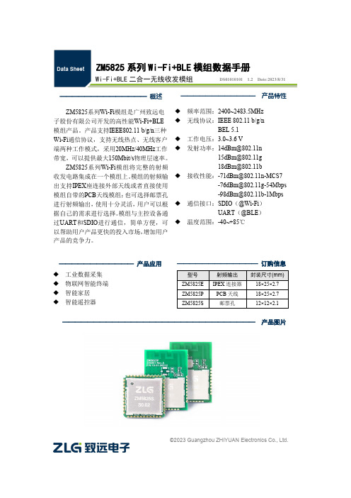
©2023 Guangzhou ZHIYUAN Electronics Co., Ltd.ZM5825系列Wi-Fi+BLE 模组数据手册Wi-Fi+BLE 二合一无线收发模组DS01010101 1.2 Date:2023/8/31———————————— 产品特性 ◆ 频率范围:2400~2483.5MHz ◆ 无线协议:IEEE 802.11 b/g/n BEL 5.1 ◆ 工作电压:3.0~3.6 V◆ 发射功率:************************** *************◆ 接收性能:************************************************************◆ 通信接口:SDIO (@Wi-Fi )UART (@BLE ) ◆ 温度范围:-40~+85℃————————————— 订购信息型号 射频输出 封装尺寸(mm) ZM5825E IPEX 连接器 18×25×2.7 ZM5825P PCB 天线 18×25×2.7 ZM5825S邮票孔12×12×2.1—————————————— 概述 ZM5825系列Wi-Fi 模组是广州致远电子股份有限公司开发的高性能Wi-Fi+BLE 模组产品。
产品支持IEEE802.11 b/g/n 三种Wi-Fi 通信协议,支持无线热点、无线客户端两种工作模式,采用20MHz/40MHz 工作带宽,可以提供最大150Mbit/s 物理层速率。
ZM5825系列Wi-Fi 模组将完整的射频收发电路集成在一个模组上。
模组的射频输出支持IPEX 座连接外部天线或者直接使用模组自带的PCB 天线模组;也可选择邮票孔进行射频输出,使用十分灵活,用户可以根据自己的需求进行选择。
模组与主控设备通过UART 和SDIO 进行通信,简单方便,可以帮助用户产品更快的投入市场,增加用户产品的竞争力。
DS13890 Rev 1 ST25R3920B 汽车级NFC读卡器 数据手册说明书

这是关于全面投产产品的信息。
2022年9月DS13890 Rev 1 [English Rev 2]1/158ST25R3920B用于CCC 数字钥匙和汽车中控台的汽车级NFC 读卡器数据手册 - 生产数据特性•AEC-Q100认证•工作模式–读卡器/写卡器–卡模拟–有源和无源点对点•RF 通信–符合EMVCo ® 3.1a 模拟和数字标准–NFC-A / ISO14443A ,高达848 kbit/s –NFC-B / ISO14443B ,高达848 kbit/s –NFC-F / Felica™,高达424 kbit/s –NFC-V / ISO15693,高达53 kb/s–NFC-A / ISO14443A (106 kbit/s )和NFC-F / FeliCa™(212/424 kbit/s )卡模拟–有源和无源点对点发起方和目标模式,高达424 kbit/s –低级模式实现了兼容MIFARE Classic ®或其他自定义协议•主要特性–动态功率输出(DPO )控制场强度,以保持在给定限制内–主动波束成形(AWS )减少过冲和下冲–噪声抑制接收器(NSR )可在噪声环境中进行接收–通过可变电容进行自动天线调谐(AAT )–集成兼容EMVCo ® 3.1a 的EMD 处理–自动增益控制和静噪功能,可最大化信噪比–低功耗NFC 主动和被动目标模式–可调ASK 调制深度,从0到82% –集成稳压器,以提升系统PSRR–AM/PM 和I/Q 解调器,提供基带通道总和或自动通道选择功能–可驱动两根独立的单端天线–测量天线电压振幅和相位、RSSI 、片上电源和稳压值•外部通信接口–512字节FIFO–串行外设接口(SPI ),高达5 Mbit/s –I2C ,高达400 kbit/s (快速模式下),1 Mbit/s (极速模式下)及3.4 Mbit/s (高速模式下)•电气特性–宽电源电压和环境温度范围(-40°C 至+105°C 为2.6至5.5 V ,-20°C 至+105°C 为2.4至5.5 V )–宽外设通信电源范围,从1.65到5.5 V–石英振荡器,使用27.12 MHz 晶振,可快速启动目录ST25R3920B 目录1应用 . . . . . . . . . . . . . . . . . . . . . . . . . . . . . . . . . . . . . . . . . . . . . . . . . . . . . . 112说明 . . . . . . . . . . . . . . . . . . . . . . . . . . . . . . . . . . . . . . . . . . . . . . . . . . . . . . 122.1系统图 . . . . . . . . . . . . . . . . . . . . . . . . . . . . . . . . . . . . . . . . . . . . . . . . . . . . 132.2框图 . . . . . . . . . . . . . . . . . . . . . . . . . . . . . . . . . . . . . . . . . . . . . . . . . . . . . 152.2.1发送器 . . . . . . . . . . . . . . . . . . . . . . . . . . . . . . . . . . . . . . . . . . . . . . . . . . 152.2.2接收器 . . . . . . . . . . . . . . . . . . . . . . . . . . . . . . . . . . . . . . . . . . . . . . . . . . 162.2.3相位和幅度检测器 . . . . . . . . . . . . . . . . . . . . . . . . . . . . . . . . . . . . . . . . . 162.2.4自动天线调谐(AAT) . . . . . . . . . . . . . . . . . . . . . . . . . . . . . . . . . . . . . . . . 162.2.5A/D转换器 . . . . . . . . . . . . . . . . . . . . . . . . . . . . . . . . . . . . . . . . . . . . . . . 162.2.6外场检测器 . . . . . . . . . . . . . . . . . . . . . . . . . . . . . . . . . . . . . . . . . . . . . . . 162.2.7石英晶体振荡器 . . . . . . . . . . . . . . . . . . . . . . . . . . . . . . . . . . . . . . . . . . . 172.2.8电源稳压器 . . . . . . . . . . . . . . . . . . . . . . . . . . . . . . . . . . . . . . . . . . . . . . . 172.2.9上电复位和基准 . . . . . . . . . . . . . . . . . . . . . . . . . . . . . . . . . . . . . . . . . . . 172.2.10RC振荡器和唤醒定时器 . . . . . . . . . . . . . . . . . . . . . . . . . . . . . . . . . . . . . 172.2.11TX编码 . . . . . . . . . . . . . . . . . . . . . . . . . . . . . . . . . . . . . . . . . . . . . . . . . . 172.2.12RX 解码 . . . . . . . . . . . . . . . . . . . . . . . . . . . . . . . . . . . . . . . . . . . . . . . . . 172.2.13FIFO . . . . . . . . . . . . . . . . . . . . . . . . . . . . . . . . . . . . . . . . . . . . . . . . . . . . 182.2.14控制逻辑 . . . . . . . . . . . . . . . . . . . . . . . . . . . . . . . . . . . . . . . . . . . . . . . . 182.2.15主机接口 . . . . . . . . . . . . . . . . . . . . . . . . . . . . . . . . . . . . . . . . . . . . . . . . 182.2.16被动目标存储器 . . . . . . . . . . . . . . . . . . . . . . . . . . . . . . . . . . . . . . . . . . . 182.2.17P2RAM . . . . . . . . . . . . . . . . . . . . . . . . . . . . . . . . . . . . . . . . . . . . . . . . . 18 3引脚和信号说明 . . . . . . . . . . . . . . . . . . . . . . . . . . . . . . . . . . . . . . . . . . . . . 194应用信息 . . . . . . . . . . . . . . . . . . . . . . . . . . . . . . . . . . . . . . . . . . . . . . . . . . 214.1上电序列 . . . . . . . . . . . . . . . . . . . . . . . . . . . . . . . . . . . . . . . . . . . . . . . . . . 214.2工作模式 . . . . . . . . . . . . . . . . . . . . . . . . . . . . . . . . . . . . . . . . . . . . . . . . . . 214.2.1发送器 . . . . . . . . . . . . . . . . . . . . . . . . . . . . . . . . . . . . . . . . . . . . . . . . . . 224.2.2接收器 . . . . . . . . . . . . . . . . . . . . . . . . . . . . . . . . . . . . . . . . . . . . . . . . . . 234.2.3天线调谐 . . . . . . . . . . . . . . . . . . . . . . . . . . . . . . . . . . . . . . . . . . . . . . . . 284.2.4唤醒模式 . . . . . . . . . . . . . . . . . . . . . . . . . . . . . . . . . . . . . . . . . . . . . . . . 294.2.5石英晶体振荡器 . . . . . . . . . . . . . . . . . . . . . . . . . . . . . . . . . . . . . . . . . . . 304.2.6定时器 . . . . . . . . . . . . . . . . . . . . . . . . . . . . . . . . . . . . . . . . . . . . . . . . . . 30 2/158DS13890 Rev 1 [English Rev 2]ST25R3920B目录4.2.7A/D转换器 . . . . . . . . . . . . . . . . . . . . . . . . . . . . . . . . . . . . . . . . . . . . . . . 334.2.8相位和幅度检测器 . . . . . . . . . . . . . . . . . . . . . . . . . . . . . . . . . . . . . . . . . 334.2.9外场检测器 . . . . . . . . . . . . . . . . . . . . . . . . . . . . . . . . . . . . . . . . . . . . . . . 344.2.10电源供电系统 . . . . . . . . . . . . . . . . . . . . . . . . . . . . . . . . . . . . . . . . . . . . . 354.2.11过冲/下冲保护 . . . . . . . . . . . . . . . . . . . . . . . . . . . . . . . . . . . . . . . . . . . . 384.2.12主动波束成形 . . . . . . . . . . . . . . . . . . . . . . . . . . . . . . . . . . . . . . . . . . . . . 394.2.13读取操作 . . . . . . . . . . . . . . . . . . . . . . . . . . . . . . . . . . . . . . . . . . . . . . . . 434.2.14侦听模式 . . . . . . . . . . . . . . . . . . . . . . . . . . . . . . . . . . . . . . . . . . . . . . . . 444.3和外部微控制器的通信 . . . . . . . . . . . . . . . . . . . . . . . . . . . . . . . . . . . . . . . 474.3.1中断接口 . . . . . . . . . . . . . . . . . . . . . . . . . . . . . . . . . . . . . . . . . . . . . . . . 474.3.2通信接口选择 . . . . . . . . . . . . . . . . . . . . . . . . . . . . . . . . . . . . . . . . . . . . . 494.3.3串行外设接口 (SPI) . . . . . . . . . . . . . . . . . . . . . . . . . . . . . . . . . . . . . . . . 494.3.4I2C接口 . . . . . . . . . . . . . . . . . . . . . . . . . . . . . . . . . . . . . . . . . . . . . . . . . 544.4直接指令 . . . . . . . . . . . . . . . . . . . . . . . . . . . . . . . . . . . . . . . . . . . . . . . . . . 584.4.1设为默认 . . . . . . . . . . . . . . . . . . . . . . . . . . . . . . . . . . . . . . . . . . . . . . . . 604.4.2停止所有动作 . . . . . . . . . . . . . . . . . . . . . . . . . . . . . . . . . . . . . . . . . . . . . 604.4.3清除 FIFO . . . . . . . . . . . . . . . . . . . . . . . . . . . . . . . . . . . . . . . . . . . . . . . 604.4.4发送指令 . . . . . . . . . . . . . . . . . . . . . . . . . . . . . . . . . . . . . . . . . . . . . . . . 614.4.5NFC开场指令 . . . . . . . . . . . . . . . . . . . . . . . . . . . . . . . . . . . . . . . . . . . . . 614.4.6含掩码接收数据和不含掩码接收数据 . . . . . . . . . . . . . . . . . . . . . . . . . . . 634.4.7更改AM调制状态 . . . . . . . . . . . . . . . . . . . . . . . . . . . . . . . . . . . . . . . . . . 634.4.8幅度测量 . . . . . . . . . . . . . . . . . . . . . . . . . . . . . . . . . . . . . . . . . . . . . . . . 634.4.9接收增益复位 . . . . . . . . . . . . . . . . . . . . . . . . . . . . . . . . . . . . . . . . . . . . . 634.4.10调准器调整 . . . . . . . . . . . . . . . . . . . . . . . . . . . . . . . . . . . . . . . . . . . . . . . 634.4.11相位测量 . . . . . . . . . . . . . . . . . . . . . . . . . . . . . . . . . . . . . . . . . . . . . . . . 644.4.12清空接收信号强度指示 . . . . . . . . . . . . . . . . . . . . . . . . . . . . . . . . . . . . . . 644.4.13透传模式 . . . . . . . . . . . . . . . . . . . . . . . . . . . . . . . . . . . . . . . . . . . . . . . . 644.4.14供电电压测量 . . . . . . . . . . . . . . . . . . . . . . . . . . . . . . . . . . . . . . . . . . . . . 644.4.15触发RC校准 . . . . . . . . . . . . . . . . . . . . . . . . . . . . . . . . . . . . . . . . . . . . . . 644.4.16进入测试 . . . . . . . . . . . . . . . . . . . . . . . . . . . . . . . . . . . . . . . . . . . . . . . . 654.5寄存器 . . . . . . . . . . . . . . . . . . . . . . . . . . . . . . . . . . . . . . . . . . . . . . . . . . . . 664.5.1IO配置寄存器1 . . . . . . . . . . . . . . . . . . . . . . . . . . . . . . . . . . . . . . . . . . . . 704.5.2IO配置寄存器2 . . . . . . . . . . . . . . . . . . . . . . . . . . . . . . . . . . . . . . . . . . . . 714.5.3操作控制寄存器 . . . . . . . . . . . . . . . . . . . . . . . . . . . . . . . . . . . . . . . . . . . 724.5.4模式定义寄存器 . . . . . . . . . . . . . . . . . . . . . . . . . . . . . . . . . . . . . . . . . . . 734.5.5比特率定义寄存器 . . . . . . . . . . . . . . . . . . . . . . . . . . . . . . . . . . . . . . . . . 754.5.6ISO14443A和NFC 106kb/s设置寄存器 . . . . . . . . . . . . . . . . . . . . . . . . . 76DS13890 Rev 1 [English Rev 2]3/158目录ST25R3920B4.5.7ISO14443B设置寄存器1 . . . . . . . . . . . . . . . . . . . . . . . . . . . . . . . . . . . . 774.5.8ISO14443B和FeliCa设置寄存器 . . . . . . . . . . . . . . . . . . . . . . . . . . . . . . 784.5.9NFCIP-1被动目标定义寄存器 . . . . . . . . . . . . . . . . . . . . . . . . . . . . . . . . 794.5.10流模式定义寄存器 . . . . . . . . . . . . . . . . . . . . . . . . . . . . . . . . . . . . . . . . . 804.5.11辅助定义寄存器 . . . . . . . . . . . . . . . . . . . . . . . . . . . . . . . . . . . . . . . . . . . 814.5.12EMD抑制配置寄存器 . . . . . . . . . . . . . . . . . . . . . . . . . . . . . . . . . . . . . . . 824.5.13副载波启动计时器寄存器 . . . . . . . . . . . . . . . . . . . . . . . . . . . . . . . . . . . . 834.5.14接收器配置寄存器1 . . . . . . . . . . . . . . . . . . . . . . . . . . . . . . . . . . . . . . . . 844.5.15接收器配置寄存器2 . . . . . . . . . . . . . . . . . . . . . . . . . . . . . . . . . . . . . . . . 854.5.16接收器配置寄存器3 . . . . . . . . . . . . . . . . . . . . . . . . . . . . . . . . . . . . . . . . 864.5.17接收器配置寄存器4 . . . . . . . . . . . . . . . . . . . . . . . . . . . . . . . . . . . . . . . . 864.5.18P2P接收器配置寄存器1 . . . . . . . . . . . . . . . . . . . . . . . . . . . . . . . . . . . . . 874.5.19相关器配置寄存器1 . . . . . . . . . . . . . . . . . . . . . . . . . . . . . . . . . . . . . . . . 884.5.20相关器配置寄存器2 . . . . . . . . . . . . . . . . . . . . . . . . . . . . . . . . . . . . . . . . 894.5.21带掩码接收定时器寄存器 . . . . . . . . . . . . . . . . . . . . . . . . . . . . . . . . . . . . 904.5.22无响应定时器寄存器1 . . . . . . . . . . . . . . . . . . . . . . . . . . . . . . . . . . . . . . 914.5.23无响应定时器寄存器2 . . . . . . . . . . . . . . . . . . . . . . . . . . . . . . . . . . . . . . 914.5.24定时器和EMV控制寄存器 . . . . . . . . . . . . . . . . . . . . . . . . . . . . . . . . . . . . 924.5.25通用定时器寄存器1 . . . . . . . . . . . . . . . . . . . . . . . . . . . . . . . . . . . . . . . . 934.5.26通用定时器寄存器2 . . . . . . . . . . . . . . . . . . . . . . . . . . . . . . . . . . . . . . . . 934.5.27PPON2场等待寄存器 . . . . . . . . . . . . . . . . . . . . . . . . . . . . . . . . . . . . . . . 944.5.28静噪定时器寄存器 . . . . . . . . . . . . . . . . . . . . . . . . . . . . . . . . . . . . . . . . . 954.5.29NFC开场保护定时器寄存器. . . . . . . . . . . . . . . . . . . . . . . . . . . . . . . . . . 954.5.30含掩码的主中断寄存器 . . . . . . . . . . . . . . . . . . . . . . . . . . . . . . . . . . . . . . 964.5.31含掩码的定时器和 NFC 中断寄存器 . . . . . . . . . . . . . . . . . . . . . . . . . . . 964.5.32含掩码的错误和唤醒中断寄存器 . . . . . . . . . . . . . . . . . . . . . . . . . . . . . . 974.5.33含掩码的被动目标中断寄存器 . . . . . . . . . . . . . . . . . . . . . . . . . . . . . . . . 974.5.34主中断寄存器 . . . . . . . . . . . . . . . . . . . . . . . . . . . . . . . . . . . . . . . . . . . . . 984.5.35定时器和NFC中断寄存器 . . . . . . . . . . . . . . . . . . . . . . . . . . . . . . . . . . . . 994.5.36错误和唤醒中断寄存器 . . . . . . . . . . . . . . . . . . . . . . . . . . . . . . . . . . . . . 1004.5.37被动目标中断寄存器 . . . . . . . . . . . . . . . . . . . . . . . . . . . . . . . . . . . . . . 1014.5.38FIFO状态寄存器1 . . . . . . . . . . . . . . . . . . . . . . . . . . . . . . . . . . . . . . . . . 1024.5.39FIFO状态寄存器2 . . . . . . . . . . . . . . . . . . . . . . . . . . . . . . . . . . . . . . . . . 1024.5.40冲突显示寄存器 . . . . . . . . . . . . . . . . . . . . . . . . . . . . . . . . . . . . . . . . . . 1034.5.41被动目标显示寄存器 . . . . . . . . . . . . . . . . . . . . . . . . . . . . . . . . . . . . . . 1044.5.42发送字节数寄存器1 . . . . . . . . . . . . . . . . . . . . . . . . . . . . . . . . . . . . . . . 1054.5.43发送字节数寄存器2 . . . . . . . . . . . . . . . . . . . . . . . . . . . . . . . . . . . . . . . 105 4/158DS13890 Rev 1 [English Rev 2]ST25R3920B目录4.5.44比特率检测显示寄存器 . . . . . . . . . . . . . . . . . . . . . . . . . . . . . . . . . . . . . 1064.5.45A/D转换器输出寄存器 . . . . . . . . . . . . . . . . . . . . . . . . . . . . . . . . . . . . . 1074.5.46天线调谐控制寄存器 1 . . . . . . . . . . . . . . . . . . . . . . . . . . . . . . . . . . . . . 1084.5.47天线调谐控制寄存器 2 . . . . . . . . . . . . . . . . . . . . . . . . . . . . . . . . . . . . . 1084.5.48TX驱动器寄存器 . . . . . . . . . . . . . . . . . . . . . . . . . . . . . . . . . . . . . . . . . . 1094.5.49辅助调制设置寄存器 . . . . . . . . . . . . . . . . . . . . . . . . . . . . . . . . . . . . . . 1114.5.50被动目标调制寄存器 . . . . . . . . . . . . . . . . . . . . . . . . . . . . . . . . . . . . . . 1124.5.51TX驱动器时序寄存器. . . . . . . . . . . . . . . . . . . . . . . . . . . . . . . . . . . . . . 1134.5.52外场检测器激活阈值寄存器 . . . . . . . . . . . . . . . . . . . . . . . . . . . . . . . . . 1144.5.53AM调制寄存器. . . . . . . . . . . . . . . . . . . . . . . . . . . . . . . . . . . . . . . . . . . 1154.5.54外场检测器取消激活阈值寄存器 . . . . . . . . . . . . . . . . . . . . . . . . . . . . . 1174.5.55TX驱动器时序显示寄存器 . . . . . . . . . . . . . . . . . . . . . . . . . . . . . . . . . . 1194.5.56稳压器电压控制寄存器 . . . . . . . . . . . . . . . . . . . . . . . . . . . . . . . . . . . . . 1204.5.57稳压器显示寄存器 . . . . . . . . . . . . . . . . . . . . . . . . . . . . . . . . . . . . . . . . 1214.5.58RSSI显示寄存器 . . . . . . . . . . . . . . . . . . . . . . . . . . . . . . . . . . . . . . . . . 1224.5.59增益减少状态寄存器 . . . . . . . . . . . . . . . . . . . . . . . . . . . . . . . . . . . . . . 1234.5.60AWS配置1寄存器 . . . . . . . . . . . . . . . . . . . . . . . . . . . . . . . . . . . . . . . . . 1244.5.61AWS配置2寄存器 . . . . . . . . . . . . . . . . . . . . . . . . . . . . . . . . . . . . . . . . . 1254.5.62辅助显示寄存器 . . . . . . . . . . . . . . . . . . . . . . . . . . . . . . . . . . . . . . . . . . 1264.5.63过冲保护配置寄存器1 . . . . . . . . . . . . . . . . . . . . . . . . . . . . . . . . . . . . . 1274.5.64过冲保护配置寄存器2 . . . . . . . . . . . . . . . . . . . . . . . . . . . . . . . . . . . . . 1274.5.65下冲保护配置寄存器1 . . . . . . . . . . . . . . . . . . . . . . . . . . . . . . . . . . . . . 1284.5.66下冲保护配置寄存器2 . . . . . . . . . . . . . . . . . . . . . . . . . . . . . . . . . . . . . 1294.5.67唤醒定时器控制寄存器 . . . . . . . . . . . . . . . . . . . . . . . . . . . . . . . . . . . . . 1304.5.68幅度测量配置寄存器 . . . . . . . . . . . . . . . . . . . . . . . . . . . . . . . . . . . . . . 1314.5.69幅度测量参考寄存器 . . . . . . . . . . . . . . . . . . . . . . . . . . . . . . . . . . . . . . 1314.5.70AWS时间1寄存器 . . . . . . . . . . . . . . . . . . . . . . . . . . . . . . . . . . . . . . . . . 1324.5.71AWS时间2寄存器 . . . . . . . . . . . . . . . . . . . . . . . . . . . . . . . . . . . . . . . . . 1324.5.72AWS时间3寄存器 . . . . . . . . . . . . . . . . . . . . . . . . . . . . . . . . . . . . . . . . . 1334.5.73AWS时间4寄存器 . . . . . . . . . . . . . . . . . . . . . . . . . . . . . . . . . . . . . . . . . 1334.5.74AWS时间5寄存器 . . . . . . . . . . . . . . . . . . . . . . . . . . . . . . . . . . . . . . . . . 1344.5.75AWS时间6寄存器 . . . . . . . . . . . . . . . . . . . . . . . . . . . . . . . . . . . . . . . . . 1344.5.76幅度测量自动取平均显示寄存器 . . . . . . . . . . . . . . . . . . . . . . . . . . . . . 1354.5.77幅度测量显示寄存器 . . . . . . . . . . . . . . . . . . . . . . . . . . . . . . . . . . . . . . 1354.5.78相位测量配置寄存器 . . . . . . . . . . . . . . . . . . . . . . . . . . . . . . . . . . . . . . 1364.5.79相位测量参考寄存器 . . . . . . . . . . . . . . . . . . . . . . . . . . . . . . . . . . . . . . 1364.5.80相位测量自动取平均显示寄存器 . . . . . . . . . . . . . . . . . . . . . . . . . . . . . 137DS13890 Rev 1 [English Rev 2]5/158目录ST25R3920B4.5.81相位测量显示寄存器 . . . . . . . . . . . . . . . . . . . . . . . . . . . . . . . . . . . . . . 1374.5.82测量TX延迟 . . . . . . . . . . . . . . . . . . . . . . . . . . . . . . . . . . . . . . . . . . . . . 1384.5.83芯片ID寄存器 . . . . . . . . . . . . . . . . . . . . . . . . . . . . . . . . . . . . . . . . . . . . 1405电气特性 . . . . . . . . . . . . . . . . . . . . . . . . . . . . . . . . . . . . . . . . . . . . . . . . . 1415.1绝对最大额定值 . . . . . . . . . . . . . . . . . . . . . . . . . . . . . . . . . . . . . . . . . . . 1415.2工作条件 . . . . . . . . . . . . . . . . . . . . . . . . . . . . . . . . . . . . . . . . . . . . . . . . . 1425.3数字输入和输出的DC/AC特性 . . . . . . . . . . . . . . . . . . . . . . . . . . . . . . . . 1435.4电气特性 . . . . . . . . . . . . . . . . . . . . . . . . . . . . . . . . . . . . . . . . . . . . . . . . . 1445.5SPI 接口特性 . . . . . . . . . . . . . . . . . . . . . . . . . . . . . . . . . . . . . . . . . . . . . 1475.6I2C 接口特性 . . . . . . . . . . . . . . . . . . . . . . . . . . . . . . . . . . . . . . . . . . . . . 1496封装信息 . . . . . . . . . . . . . . . . . . . . . . . . . . . . . . . . . . . . . . . . . . . . . . . . . 1546.1VFQFPN32封装信息 . . . . . . . . . . . . . . . . . . . . . . . . . . . . . . . . . . . . . . . 154 7订购信息 . . . . . . . . . . . . . . . . . . . . . . . . . . . . . . . . . . . . . . . . . . . . . . . . . 156 8版本历史 . . . . . . . . . . . . . . . . . . . . . . . . . . . . . . . . . . . . . . . . . . . . . . . . . 1576/158DS13890 Rev 1 [English Rev 2]ST25R3920B表格索引表格索引表1.ST25R3920BVFQFPN32 引脚分配 . . . . . . . . . . . . . . . . . . . . . . . . . . . . . . . . . . . . . . . . . . 19表2.RX通道选择 . . . . . . . . . . . . . . . . . . . . . . . . . . . . . . . . . . . . . . . . . . . . . . . . . . . . . . . . . . . . 24表3.低通控制. . . . . . . . . . . . . . . . . . . . . . . . . . . . . . . . . . . . . . . . . . . . . . . . . . . . . . . . . . . . . . . 25表4.第一级和第三级零点设置 . . . . . . . . . . . . . . . . . . . . . . . . . . . . . . . . . . . . . . . . . . . . . . . . . . 26表5.用于OOK和ASK 模式下的低速、中速和快速传输的典型预设值. . . . . . . . . . . . . . . . . . . . . 40表6.PT_Memory地址空间 . . . . . . . . . . . . . . . . . . . . . . . . . . . . . . . . . . . . . . . . . . . . . . . . . . . . . 45表7.NFC-212/424k SENS_RES格式. . . . . . . . . . . . . . . . . . . . . . . . . . . . . . . . . . . . . . . . . . . . . 46表8.IRQ输出 . . . . . . . . . . . . . . . . . . . . . . . . . . . . . . . . . . . . . . . . . . . . . . . . . . . . . . . . . . . . . . . 47表9.串行数据接口(4线接口)信号线 . . . . . . . . . . . . . . . . . . . . . . . . . . . . . . . . . . . . . . . . . . . . 49表10.SPI工作模式 . . . . . . . . . . . . . . . . . . . . . . . . . . . . . . . . . . . . . . . . . . . . . . . . . . . . . . . . . . . . 50表11.I2C接口和中断信号线. . . . . . . . . . . . . . . . . . . . . . . . . . . . . . . . . . . . . . . . . . . . . . . . . . . . . 55表12.直接指令列表 . . . . . . . . . . . . . . . . . . . . . . . . . . . . . . . . . . . . . . . . . . . . . . . . . . . . . . . . . . . 58表13.NFC 开场指令的时序参数. . . . . . . . . . . . . . . . . . . . . . . . . . . . . . . . . . . . . . . . . . . . . . . . . . 62表14.模拟测试和查看寄存器1 . . . . . . . . . . . . . . . . . . . . . . . . . . . . . . . . . . . . . . . . . . . . . . . . . . . 65表15.T测试通道寄存器 - TAD1 和TAD2 管脚信号选择 . . . . . . . . . . . . . . . . . . . . . . . . . . . . . . . . 65表16.寄存器列表 - 空间A. . . . . . . . . . . . . . . . . . . . . . . . . . . . . . . . . . . . . . . . . . . . . . . . . . . . . . . 66表17.寄存器列表 - 空间B. . . . . . . . . . . . . . . . . . . . . . . . . . . . . . . . . . . . . . . . . . . . . . . . . . . . . . . 68表18.IO配置寄存器1 . . . . . . . . . . . . . . . . . . . . . . . . . . . . . . . . . . . . . . . . . . . . . . . . . . . . . . . . . . 70表19.IO配置寄存器2 . . . . . . . . . . . . . . . . . . . . . . . . . . . . . . . . . . . . . . . . . . . . . . . . . . . . . . . . . . 71表20.操作控制寄存器. . . . . . . . . . . . . . . . . . . . . . . . . . . . . . . . . . . . . . . . . . . . . . . . . . . . . . . . . . 72表21.模式定义寄存器. . . . . . . . . . . . . . . . . . . . . . . . . . . . . . . . . . . . . . . . . . . . . . . . . . . . . . . . . . 73表22.初始化操作模式. . . . . . . . . . . . . . . . . . . . . . . . . . . . . . . . . . . . . . . . . . . . . . . . . . . . . . . . . . 73表23.目标工作模式 . . . . . . . . . . . . . . . . . . . . . . . . . . . . . . . . . . . . . . . . . . . . . . . . . . . . . . . . . . . 73表24.比特率定义寄存器. . . . . . . . . . . . . . . . . . . . . . . . . . . . . . . . . . . . . . . . . . . . . . . . . . . . . . . . 75表25.比特率编码 . . . . . . . . . . . . . . . . . . . . . . . . . . . . . . . . . . . . . . . . . . . . . . . . . . . . . . . . . . . . . 75表26.ISO14443A和NFC 106kb/s设置寄存器. . . . . . . . . . . . . . . . . . . . . . . . . . . . . . . . . . . . . . . . 76表27.调制脉冲宽度 . . . . . . . . . . . . . . . . . . . . . . . . . . . . . . . . . . . . . . . . . . . . . . . . . . . . . . . . . . . 76表28.ISO14443B设置寄存器1. . . . . . . . . . . . . . . . . . . . . . . . . . . . . . . . . . . . . . . . . . . . . . . . . . . 77表29.ISO14443B和FeliCa设置寄存器. . . . . . . . . . . . . . . . . . . . . . . . . . . . . . . . . . . . . . . . . . . . . 78表30.最小TR1编码. . . . . . . . . . . . . . . . . . . . . . . . . . . . . . . . . . . . . . . . . . . . . . . . . . . . . . . . . . . . 78表31.NFCIP-1被动目标定义寄存器 . . . . . . . . . . . . . . . . . . . . . . . . . . . . . . . . . . . . . . . . . . . . . . . 79表32.流模式定义寄存器. . . . . . . . . . . . . . . . . . . . . . . . . . . . . . . . . . . . . . . . . . . . . . . . . . . . . . . . 80表33.副载波流模式的副载波频率定义 . . . . . . . . . . . . . . . . . . . . . . . . . . . . . . . . . . . . . . . . . . . . . 80表34.流模式Tx调制器控制的时间周期定义 . . . . . . . . . . . . . . . . . . . . . . . . . . . . . . . . . . . . . . . . . 80表35.辅助定义寄存器. . . . . . . . . . . . . . . . . . . . . . . . . . . . . . . . . . . . . . . . . . . . . . . . . . . . . . . . . . 81表36.EMD抑制配置寄存器. . . . . . . . . . . . . . . . . . . . . . . . . . . . . . . . . . . . . . . . . . . . . . . . . . . . . . 82表37.副载波启动计时器寄存器 . . . . . . . . . . . . . . . . . . . . . . . . . . . . . . . . . . . . . . . . . . . . . . . . . . 83表38.接收器配置寄存器1. . . . . . . . . . . . . . . . . . . . . . . . . . . . . . . . . . . . . . . . . . . . . . . . . . . . . . . 84表39.接收器配置寄存器2. . . . . . . . . . . . . . . . . . . . . . . . . . . . . . . . . . . . . . . . . . . . . . . . . . . . . . . 85表40.接收器配置寄存器3. . . . . . . . . . . . . . . . . . . . . . . . . . . . . . . . . . . . . . . . . . . . . . . . . . . . . . . 86表41.接收器配置寄存器4. . . . . . . . . . . . . . . . . . . . . . . . . . . . . . . . . . . . . . . . . . . . . . . . . . . . . . . 86表42.P2P接收器配置寄存器1 . . . . . . . . . . . . . . . . . . . . . . . . . . . . . . . . . . . . . . . . . . . . . . . . . . . 87表43.OOK阈值设置. . . . . . . . . . . . . . . . . . . . . . . . . . . . . . . . . . . . . . . . . . . . . . . . . . . . . . . . . . . 87表44.相关器配置寄存器1. . . . . . . . . . . . . . . . . . . . . . . . . . . . . . . . . . . . . . . . . . . . . . . . . . . . . . . 88表45.相关器配置寄存器2. . . . . . . . . . . . . . . . . . . . . . . . . . . . . . . . . . . . . . . . . . . . . . . . . . . . . . . 89表46.含掩码接收定时器寄存器 . . . . . . . . . . . . . . . . . . . . . . . . . . . . . . . . . . . . . . . . . . . . . . . . . . 90表47.无响应定时器寄存器1. . . . . . . . . . . . . . . . . . . . . . . . . . . . . . . . . . . . . . . . . . . . . . . . . . . . . 91表48.无响应定时器寄存器2. . . . . . . . . . . . . . . . . . . . . . . . . . . . . . . . . . . . . . . . . . . . . . . . . . . . . 91DS13890 Rev 1 [English Rev 2]7/158表格索引ST25R3920B 表49.定时器和EMV控制寄存器 . . . . . . . . . . . . . . . . . . . . . . . . . . . . . . . . . . . . . . . . . . . . . . . . . . 92表50.触发源. . . . . . . . . . . . . . . . . . . . . . . . . . . . . . . . . . . . . . . . . . . . . . . . . . . . . . . . . . . . . . . . . 92表51.通用定时器寄存器1. . . . . . . . . . . . . . . . . . . . . . . . . . . . . . . . . . . . . . . . . . . . . . . . . . . . . . . 93表52.通用定时器寄存器2. . . . . . . . . . . . . . . . . . . . . . . . . . . . . . . . . . . . . . . . . . . . . . . . . . . . . . . 93表53.PPON2场等待寄存器 . . . . . . . . . . . . . . . . . . . . . . . . . . . . . . . . . . . . . . . . . . . . . . . . . . . . . 94表54.静噪定时器寄存器. . . . . . . . . . . . . . . . . . . . . . . . . . . . . . . . . . . . . . . . . . . . . . . . . . . . . . . . 95表55.NFC 开场保护定时器寄存器 . . . . . . . . . . . . . . . . . . . . . . . . . . . . . . . . . . . . . . . . . . . . . . . . 95表56.掩码的主中断寄存器. . . . . . . . . . . . . . . . . . . . . . . . . . . . . . . . . . . . . . . . . . . . . . . . . . . . . . 96表57.掩码定时器和NFC 中断寄存器 . . . . . . . . . . . . . . . . . . . . . . . . . . . . . . . . . . . . . . . . . . . . . . 96表58.掩码错误和唤醒中断寄存器. . . . . . . . . . . . . . . . . . . . . . . . . . . . . . . . . . . . . . . . . . . . . . . . . 97表59.含掩码的被动目标中断寄存器. . . . . . . . . . . . . . . . . . . . . . . . . . . . . . . . . . . . . . . . . . . . . . . 97表60.主中断寄存器 . . . . . . . . . . . . . . . . . . . . . . . . . . . . . . . . . . . . . . . . . . . . . . . . . . . . . . . . . . . 98表61.定时器和NFC中断寄存器 . . . . . . . . . . . . . . . . . . . . . . . . . . . . . . . . . . . . . . . . . . . . . . . . . . 99表62.错误和唤醒中断寄存器 . . . . . . . . . . . . . . . . . . . . . . . . . . . . . . . . . . . . . . . . . . . . . . . . . . . 100表63.被动目标中断寄存器. . . . . . . . . . . . . . . . . . . . . . . . . . . . . . . . . . . . . . . . . . . . . . . . . . . . . 101表64.FIFO状态寄存器1 . . . . . . . . . . . . . . . . . . . . . . . . . . . . . . . . . . . . . . . . . . . . . . . . . . . . . . . 102表65.FIFO状态寄存器2 . . . . . . . . . . . . . . . . . . . . . . . . . . . . . . . . . . . . . . . . . . . . . . . . . . . . . . . 102表66.冲突显示寄存器. . . . . . . . . . . . . . . . . . . . . . . . . . . . . . . . . . . . . . . . . . . . . . . . . . . . . . . . . 103表67.被动目标显示寄存器. . . . . . . . . . . . . . . . . . . . . . . . . . . . . . . . . . . . . . . . . . . . . . . . . . . . . 104表68.发送字节数寄存器1. . . . . . . . . . . . . . . . . . . . . . . . . . . . . . . . . . . . . . . . . . . . . . . . . . . . . . 105表69.发送字节数寄存器2 . . . . . . . . . . . . . . . . . . . . . . . . . . . . . . . . . . . . . . . . . . . . . . . . . . . . . 105表70.比特率检测显示寄存器 . . . . . . . . . . . . . . . . . . . . . . . . . . . . . . . . . . . . . . . . . . . . . . . . . . . 106表71.A/D转换器输出寄存器. . . . . . . . . . . . . . . . . . . . . . . . . . . . . . . . . . . . . . . . . . . . . . . . . . . . 107表72.天线调谐控制寄存器1. . . . . . . . . . . . . . . . . . . . . . . . . . . . . . . . . . . . . . . . . . . . . . . . . . . . 108表73.天线调谐控制寄存器2. . . . . . . . . . . . . . . . . . . . . . . . . . . . . . . . . . . . . . . . . . . . . . . . . . . . 108表74.TX驱动器寄存器 . . . . . . . . . . . . . . . . . . . . . . . . . . . . . . . . . . . . . . . . . . . . . . . . . . . . . . . . 109表75.AM调制指数 . . . . . . . . . . . . . . . . . . . . . . . . . . . . . . . . . . . . . . . . . . . . . . . . . . . . . . . . . . . 109表76.RFO驱动阻抗 . . . . . . . . . . . . . . . . . . . . . . . . . . . . . . . . . . . . . . . . . . . . . . . . . . . . . . . . . . 110表77.辅助调制设置寄存器. . . . . . . . . . . . . . . . . . . . . . . . . . . . . . . . . . . . . . . . . . . . . . . . . . . . . 111表78.被动目标调制寄存器. . . . . . . . . . . . . . . . . . . . . . . . . . . . . . . . . . . . . . . . . . . . . . . . . . . . . 112表79.被动目标调制和未调制状态驱动器输出电阻 . . . . . . . . . . . . . . . . . . . . . . . . . . . . . . . . . . . 112表80.TX驱动器时序寄存器 . . . . . . . . . . . . . . . . . . . . . . . . . . . . . . . . . . . . . . . . . . . . . . . . . . . . 113表81.外场检测器激活阈值寄存器. . . . . . . . . . . . . . . . . . . . . . . . . . . . . . . . . . . . . . . . . . . . . . . . 114表82.电阻性AM调制寄存器 . . . . . . . . . . . . . . . . . . . . . . . . . . . . . . . . . . . . . . . . . . . . . . . . . . . . 115表83.电阻性AM调制状态驱动器输出电阻 . . . . . . . . . . . . . . . . . . . . . . . . . . . . . . . . . . . . . . . . 115表84.外场检测器取消激活阈值寄存器 . . . . . . . . . . . . . . . . . . . . . . . . . . . . . . . . . . . . . . . . . . . . 117表85.RFI1输入上的对端检测阈值 . . . . . . . . . . . . . . . . . . . . . . . . . . . . . . . . . . . . . . . . . . . . . . . 118表86.RFI1输入上的防冲突阈值 . . . . . . . . . . . . . . . . . . . . . . . . . . . . . . . . . . . . . . . . . . . . . . . . . 118表87.TX驱动器时序显示寄存器. . . . . . . . . . . . . . . . . . . . . . . . . . . . . . . . . . . . . . . . . . . . . . . . . 119表88.稳压器电压控制寄存器 . . . . . . . . . . . . . . . . . . . . . . . . . . . . . . . . . . . . . . . . . . . . . . . . . . . 120表89.稳压器显示寄存器. . . . . . . . . . . . . . . . . . . . . . . . . . . . . . . . . . . . . . . . . . . . . . . . . . . . . . . 121表90.稳压值. . . . . . . . . . . . . . . . . . . . . . . . . . . . . . . . . . . . . . . . . . . . . . . . . . . . . . . . . . . . . . . . 121表91.RSSI显示寄存器. . . . . . . . . . . . . . . . . . . . . . . . . . . . . . . . . . . . . . . . . . . . . . . . . . . . . . . . 122表92.接收信号强度指示. . . . . . . . . . . . . . . . . . . . . . . . . . . . . . . . . . . . . . . . . . . . . . . . . . . . . . . 122表93.增益减少状态寄存器. . . . . . . . . . . . . . . . . . . . . . . . . . . . . . . . . . . . . . . . . . . . . . . . . . . . . 123表94.AWS配置 1 . . . . . . . . . . . . . . . . . . . . . . . . . . . . . . . . . . . . . . . . . . . . . . . . . . . . . . . . . . . 124表95.AWS配置 2 . . . . . . . . . . . . . . . . . . . . . . . . . . . . . . . . . . . . . . . . . . . . . . . . . . . . . . . . . . . 125表96.辅助显示寄存器. . . . . . . . . . . . . . . . . . . . . . . . . . . . . . . . . . . . . . . . . . . . . . . . . . . . . . . . . 126表97.过冲保护配置寄存器1. . . . . . . . . . . . . . . . . . . . . . . . . . . . . . . . . . . . . . . . . . . . . . . . . . . . 127表98.过冲保护配置寄存器2. . . . . . . . . . . . . . . . . . . . . . . . . . . . . . . . . . . . . . . . . . . . . . . . . . . . 127表99.下冲保护配置寄存器1. . . . . . . . . . . . . . . . . . . . . . . . . . . . . . . . . . . . . . . . . . . . . . . . . . . . 128表100.下冲保护配置寄存器2. . . . . . . . . . . . . . . . . . . . . . . . . . . . . . . . . . . . . . . . . . . . . . . . . . . . 129 8/158DS13890 Rev 1 [English Rev 2]。
ATJ2091N Datasheet V1.1
Copyright © Actions Semiconductor Co., Ltd 2007. All rights reserved. Ver. 1.11/46 2007-3-22ATJ2091N DatasheetVersion 1.1DeclarationCircuit diagrams and other information relating to products of Actions Semiconductor Company, Ltd. (“Actions”) are included as a means or illustrating typical applications. Consequently, complete information sufficient for construction purposes is not necessarily given. Although the information has been examined and is believed to be accurate, Actions makes no representations or warranties with respect to the accuracy or completeness of the contents of this publication and disclaims any responsibility for inaccuracies. Information in this document is provided solely to enable use of Actions’ products. The information presented in this document does not form part of any quotation or contract for sale. Actions assumes no liability whatsoever, including infringement of any patent or copyright, for sale and use of Actions’ products, except as may expressly be provided in Actions’ Terms and Conditions of Sale for such products. All sales of any Actions products are expressly conditional on your agreement to the terms and conditions of the most recently dated version of Actions’ Terms and Conditions of Sale Agreement dated before the date of your order.The provision of this information does not convey to the purchaser of the described semiconductor devices any licenses under any patent rights, copyright, trademark rights, rights in trade secrets and/or know how, or any other intellectual property rights of Actions or others, however denominated, whether by express or implied representation, by estoppel, or otherwise.Information contained herein relates solely to the Actions products described herein and abrogates and supersedes, as of the release date of this publication, all previously published data and specifications relating to such products provided by Actions or by any other person purporting to distribute such information. Actions reserves the right to make changes to specifications and product descriptions at any time without notice. Contact your Actions sales representative to obtain the latest specifications before placing your product order. Actions product may contain design defects or errors known as anomalies or errata which may cause the products functions to deviate from published specifications. Anomaly or “errata” sheets relating to currently characterized anomalies or errata are available upon request. Designers must not rely on the absence or characteristics of any features or instructions of Actions’ products marked “reserved” or “undefined.” Actions reserves these for future definition and shall have no responsibility whatsoever for conflicts or incompatibilities arising from future changes to them.Actions’ products are not designed, intended, authorized or warranted for use in any life support or other application where product failure could cause or contribute to personal injury or severe property damage. Any and all such uses without prior written approval of an OfficerCopyright© Actions Semiconductor Co., Ltd 2007. All rights reserved.Ver. 1.1 2/46 2007-3-22Copyright © Actions Semiconductor Co., Ltd 2007. All rights reserved. Ver. 1.13/46 2007-3-22 of Actions and further testing and/or modification will be fully at the risk of the customer. Copies of this document and/or other Actions product literature, as well as the Terms and Conditions of Sale Agreement, may be obtained by visiting Actions’ website at http:/ or from an authorized Actions representative. The word “ACTIONS,” the Actions’ LOGO, whether used separately and/or in combination, and the phase “ATJ2097,” are trademarks of Actions Semiconductor Company, Ltd.. Names and brands of other companies and their products that may from time to time descriptively appear in this product data sheet are the trademarks of their respective holders: no affiliation, authorization, or endorsement by such persons is claimed or implied except as may be expressly stated therein. ACTIONS DISCLAIMS AND EXCLUDES ANY AND ALL WARRANTIES, INCLUDING WITHOUT LIMITATION ANY AND ALL IMPLIED WARRANTIES OF MERCHANTABILITY, FITNESS FOR A PARTICULAR PURPOSE, TITLE, AND AGAINST INFRINGEMENT AND THE LIKE, AND ANY AND ALL WARRANTIES ARISING FROM ANY COURSE OF DEALING OR USAGE OF TRADE.IN NO EVENT SHALL ACTIONS BE RELIABLE FOR ANY DIRECT, INCIDENTAL, INDIRECT, SPECIAL, PUNITIVE, OR CONSEQUENTIAL DAMAGES; OR FOR LOST DATA, PROFITS, SAVINGS OR REVENUES OF ANY KIND; REGARDLESS OF THE FORM OF ACTION, WHETHER BASED ON CONTRACT; TORT; NEGLIGENCE OF ACTIONS OR OTHERS; STRICT LIABILITY; BREACH OF WARRANTY; OR OTHERWISE; WHETHER OR NOT ANY REMEDY OF BUYER IS HELD TO HAVE FAILED OF ITS ESSENTIAL PURPOSE, AND WHETHER ACTIONS HAS BEEN ADVISED OF THE POSSIBILITY OF SUCH DAMAGES OR NOT.Additional SupportAdditional product and company information can be obtained by visiting the Actions website at: Table of ContentsRevision History (6)1 .Introduction (7)2. Pin Description (10)2.1 Pin Out (10)2.2 Pin Definition (10)3. Function Description (14)3.1 Functional Block Diagram (14)3.2 MCU Core (15)3.2.1 MCU System Memory Mapping (15)3.3 DSP24 Core (17)3.4 ZRAM1 and ZRAM2 (17)3.5 USB2.0 SIE (18)3.5.1 General Description (18)3.5.2 Features (19)3.5.3 USB Using Memory (20)3.6 NAND Flash Interface (20)3.7 Key Scan Interface (20)3.8 LCD Interface (21)3.9 General Purpose IO Ports (23)3.10 LOSC/RTC (23)3.11 HOSC/PLL (24)3.12 PMU/DC-DC (25)3.13 A/D, D/A and Headphone Driver (25)3.13.1 D/A Interface (25)3.13.2 A/D Interface (26)4. Electrical Characteristics (27)4.1 Absolute Maximum Ratings (27)Copyright© Actions Semiconductor Co., Ltd 2007. All rights reserved. Ver. 1.1 4/46 2007-3-22Copyright © Actions Semiconductor Co., Ltd 2007. All rights reserved. Ver. 1.15/46 2007-3-22 4.2 Capacitance (27)4.3 DC Characteristics (28)4.4 AC Characteristics (29)4.4.1 AC Test Input Waveform (29)4.4.2 AC Test Output Measuring Points (29)4.4.3 Reset Parameter (30)4.4.4 Initialization Parameter (30)4.4.5 GPIO Interface Parameter (30)4.4.6 Ordinary ROM Parameter (31)4.4.7 External System Bus Parameter (33)4.4.8 Bus Operation (34)4.4.9 Serial Interface Parameter (34)4.4.10 A/D Converter Characteristics (36)4.4.11 I2S Interface Parameter (36)4.4.12 Headphone Driver Characteristics Table (36)4.4.13 LCM Driver Parameter (38)4.4.14 SPI Parameter (39)5. Ordering Information (41)5.1 Soldering Conditions (41)5.2 Precaution Against ESD For Semiconductors (41)5.3 Status Before Initialization of MOS Devices (42)6. ATJ 2091N Package Drawing (43)7. Appendix (44)Copyright © Actions Semiconductor Co., Ltd 2007. All rights reserved. Ver. 1.16/46 2007-3-22 Revision History Version Date DescriptionVer1.0 Nov. 2006 1st version created for ATJ2091NVer1.1 Mar. 2007 2nd version modified for ATJ2091N, electrical characteristics added.1 .IntroductionATJ2091N is a third generation single-chip highly-integrated digital music system solution for devices such as dedicated audio players, PDAs, and cell phones. It includes an audio decoder with a high performance DSP with embedded RAM and ROM, ADPCM record capabilities and USB interface for downloading music and uploading voice recordings. ATJ2091N also provides an interface flash memory, LED/LCD, button and switch inputs, headphones, microphone and FM radio input and control. ATJ2091N contains a high performance DSP, which can easily be programmed to support many kinds of digital audio standards such as WMA, etc. For devices like USB-Disk, ATJ2091N can act as a USB mass storage slave device to personal computer system. ATJ2091N has low power consumption to allow long battery life and an efficient flexible on-chip DC-DC converter that allows many different battery configurations, including 1xAA and 1xAAA. The built-in Sigma-Delta DAC includes a headphone driver to directly drive low impedance headphones. The ADC includes inputs for both Microphone and Analog Audio in to support voice recording and FM radio integration features. ATJ2091N provides a true “ALL-IN-ONE” solution that is ideally suited for highly optimized digital audio players.Features:z MPEG1/2/2.5 Audio Layer 1,2,3 decoder, bit rate 8-448Kbps, 8-48KHz, CBR/VBRz Support WMA Decoder, bit rate 32-384Kbps, 8-48KHzz Digital Voice Recording at ultra low 4.4 or 8Kbps w/ Actions Speech Algorithmz24 bits DSP Core with on-chip Debug Support Unit (DSU)Copyright© Actions Semiconductor Co., Ltd 2007. All rights reserved.Ver. 1.1 7/46 2007-3-22Copyright © Actions Semiconductor Co., Ltd 2007. All rights reserved. Ver. 1.18/46 2007-3-22 z On-chip DSP PM with SRAM(16K*24) ,can be switched to be MCU memory space z On-chip DSP DM with SRAM(16K*24), can be switched to be MCU memory space z Integrated MCU with DSU, the instruction set is compatible with Z80z Internal (16K-64)x8(ZRAM1),(3K+3K)(ZRAM2) and 6k ZRAM3 accessed by MCU z Internal 12Kx8 BROM build in Boot up and USB Upgrade firmwarez Internal (21K+17K)x8 TROMz Internal SRAM access time<7ns, MROM access time<16nsz External up to 3(pcs)x 32M/64M/128M/256M/512M/1G/2G/4G bytes Nand type Flashaccessed by MCU or DMAz Support 24MHz OSC with on-chip PLL for DSP and about 32KHz RC oscillator z 2-channel DMA , 1-channel CTC(Counter/Timer Controller) and interrupt controller forMCUz Energy saving dynamic power management (PMU), supporting 1xAA and 1xAAA. z Support USB 2.0 Compliance PHY+SIE, Read :7MB/S, Write: 6MB/S( Nand FlashBase )z Build in Stereo 18-bit Sigma-Delta D/Az Build in Key Scan Circuit and GPIOz Support external 8080 Series LCM driver interfacez Support FM Radio input and 32 levels volume controlz Support Stereo 18-bit Sigma-Delta A/D for Microphone/FM Input/Line Input, samplerate at 8/12/16/22/24/32/48KHzz MCU run at 48MHz(typ),F/W can program from DC up to 60MHz transparently z DSP+PM/DM Speed up to 72MIPS,while 48mips@1.4vz D/A+PA SNR :with A weight>92dB,without A weight>=88dBz A/D SNR >79dBCopyright © Actions Semiconductor Co., Ltd 2007. All rights reserved. Ver. 1.19/46 2007-3-22 z Headphone driver output 2x11Mw @16ohmz Operating Voltage: IO: 3.0v, Core: 1.8vz Standby Leakage Current: VCC:50uA@3.0V(MAX), VDD: 350uA@1.6V(MAX) z Low Power Consumption : <80mW@1.5V at typical WMA decoder solutionCopyright © Actions Semiconductor Co., Ltd 2007. All rights reserved. Ver. 1.110/46 2007-3-22 2. Pin Description2.1 Pin Out2.2 Pin DefinitionNOTE:1: PWR---Power Supply2: AI----Analog InputCopyright © Actions Semiconductor Co., Ltd 2007. All rights reserved. Ver. 1.111/46 2007-3-223: AO----Analog Output 4: O-----Output 5: I-----Input 6: BI----Bidirection 7: TBD2C, BD2C, BD2XU, SBD2X, BD2XM5----2 miliampere driver 8: BD4CM2, BD4C, BD4CU----4 miliampere driver 9: BD1XM2----1 miliampere driver 10:USCU----USCHIMITCU Pin No. Pin Name I/O Type Driver Reset Default Description 1 VCC PWR / / Power supply for USB 2UREGAO / / USB precision Resistor 3 GND PWR / / USB ground 4 USBDP A / H USB data plus 5 USBDM A / H USB data minus6 RESET- I USCU H System reset input (active low)7 PAVCC PWR / / Power supply for power amplifier8 AOUTR AO / / Int. PA right channel analog output9 AOUTL AO / / Int. PA left channel analog output 10 PAGND PWR / / Power amplifier ground11VRDAAO / / Bypass capacitor connect pin for Int. D/A Reference voltage12 MICIN AI / / Microphone pre-amplifier input 13 VMIC PWR / / Power supply for Microphone 14FMINLAI / / Left channel of FM line input 15 FMINR AI / / Right channel of FM line input 16 AGND PWR / / Analog ground 17 AVCC PWR / / power supply of Analog 18 VREFI AI / / Voltage reference input 19 AVDD PWR / / Analog Core power pin 20VDDIOPWR/ZCore power input/outputCopyright © Actions Semiconductor Co., Ltd 2007. All rights reserved. Ver. 1.112/46 2007-3-2221 VP PWR / / Power pin22 LRADC1 AI / / Low resolution A/D input 1 23 PWRMode0 AI / / POWER mode select 024 HOSCI AI / / High frequency crystal OSC input 25 HOSCO AO / / High frequency crystal OSC output 26 VCC PWR / / PAD power pin 27 BAT I / / Battery Voltage input.GPIO_B0BIZ Bit0 of General purpose I/O port B 28KEYI0 I BD2CH Bit0 of key scan circuit input 29 GPIO_C2 BI BD4CM2/ Bit2 of General purpose I/O port C GPIO_B2BIZ Bit2 of General purpose I/O port B 30 KEYI12 I BD2XUM5 H Bit1 of key scan circuit input 31LXVDDPWR// VDD DC-DC pin 32 GND PWR / / Ground 33 GND PWR / / NMOS Ground 34 LXVCC PWR / / VCC DC-DC pin35 CE2- O NF_PAD H Ext. memory chip enable 2 36 CE1- O NF_PAD H Ext. memory chip enable 1 CE3-OH Ext. memory chip enable 337GPO_A3 O BD4CU/Bit3 of General purpose Output port A GPIO_G0BIZ Bit0 of General purpose I/O port G 38CE4- O TBD2C/ Ext. memory chip enable 4 39 VDD PWR / / Digital Core power40 RB- I BD4C H Nand Type flash Ready/Busy status input.GPO_A1OL Bit1 of General purpose Output port A 41 ICECK I BD4C/Clock input of DSUGPO_A2OL Bit2 of General purpose Output port A 42 ICEDO O BD4C/ Data output of DSUGPO_A0OBD4CM2Bit0 of General purpose Output port ACopyright © Actions Semiconductor Co., Ltd 2007. All rights reserved. Ver. 1.113/46 2007-3-2243 ICEDI I / Data input of DSU 44 ICEEN- I BD4C / DSU enable (active low) 45 ICERST- I BD4C / DSU reset (active low)GPIO_B4BIZ Bit4 of General purpose I/O port B 46KEYO0 O BD2XM5/ Bit0 of key scan circuit output GPIO_B5BIZ Bit5 of General purpose I/O port B 47KEYO1 O BD2XM5/ Bit1 of key scan circuit output 48 VCC PWR / / Digital power pad49 D7 BI NF_PAD L Bit7 of ext. memory data bus 50 D6 BI NF_PAD L Bit6 of ext. memory data bus 51 D5 BI NF_PAD L Bit5 of ext. memory data bus 52 D4 BI NF_PAD L Bit4 of ext. memory data bus 53 D3 BI NF_PAD L Bit3 of ext. memory data bus 54D2BINF_PADL Bit2 of ext. memory data bus 55 GND PWR / / Ground56 D1 BI NF_PAD L Bit1 of ext. memory data bus 57 D0 BI NF_PAD L Bit0 of ext. memory data bus 58 MWR- O NF_PAD H Ext. memory write strobe 59MRD-O NF_PAD H Ext. memory read strobe60 CLE O NF_PAD L Command latch enable for NAND flash61 ALE O NF_PAD L Address latch enable for NAND flash GPIO_C1 BI OD Bit1 of General purpose I/O port C I2C_SDAO/ I2C Serial data (Open drain) 62SIRQ- I SBD2X/ Ext. interrupt request input GPIO_C0BIOD Bit0 of General purpose I/O port C 63I2C_SCL OSBD2X / I2C serial clock (Open drain) 64 VDDPWR//Digital Core power3. Function Description3.1 Functional Block DiagramCopyright© Actions Semiconductor Co., Ltd 2007. All rights reserved. Ver. 1.1 14/46 2007-3-22Copyright © Actions Semiconductor Co., Ltd 2007. All rights reserved. Ver. 1.115/46 2007-3-223.2 MCU Core3.2.1 MCU System Memory MappingEntendedMemory Space (MCU.A15=1)Internal Memory Space (MCU.A15=0)MCU 64KB Memory Space 0000H8000H FFFFHIf IA15=0 -> mapped to internal MemoryIf IA14=0, mapped to internal ZRAM (16K-64 ZRAM1)If IA14=1, mapped to internal DSP IPM/IDM when they are mapped into MCU memory space 3 extended address bits of a IO mapped register (Mapped at registered are used to decode the access to one of these memory blocks Bit 2 1 0 Accessed Block 0 0 0IPM low byteCopyright © Actions Semiconductor Co., Ltd 2007. All rights reserved. Ver. 1.116/46 2007-3-220 0 1 IPM middle byte 0 1 0 IPM high byte 0 1 1 ZRAM3 1 0 0 IDM low byte 1 0 1 IDM middle byte 1 1 0 IDM high byte 1 1 1ZRAM2 (B1+B2)Since IPM/IDM is mapped to MCU memory space per 8K block, IA13 is used toselect low/high block of 8K bytes in each 16K byte block.If IA15=1 -> Extended address bits are IO mapped at 01h and 02h for EMA15-28.EMA15-25 are output as address bus, while the EMA26-28 are used to decode CE0- ~ CE3-.CE0- is used to access boot code from ROM/MASK/NOR- type Flash.CE1- to CE3- can be configured to access ROM, or RAM or NAND-type Flash.ATJ2091N’s internal MCU MROM/SRAM memory mapping:1) (16K-64) byte ZRAM1(IA15=0,IA14=0): 0000H-3FBFH2) 6Kbyte ZRAM2 (IA15=0, IA14=1, IOReg05.[2:0]=111): 4000H-57FFH 3) (2K+256) byte URAM: 5800H-60FFH it has synchronization andasynchronism accessing mode.4) 12Kbyte BROM (IA15=1,Reg02=00h, Reg01=00h): 8000h-AFFFh 5) 21Kbyte TROM1 (IA15=1,Reg02=00h,Reg01=02h): 8000h-D3FFh 6) 17Kbyte TROM2 (IA15=1,Reg02=00h,Reg01=03h): 8000h-C400h 7) 6Kbyte ZRAM3 (IA15=0,IA14=1,IOReg05.[2:0]=011): 4000H-57FFHCopyright © Actions Semiconductor Co., Ltd 2007. All rights reserved. Ver. 1.117/46 2007-3-22ATJ2091N’s internal DSP IPM/IDM memory mapping:1) 16K x24bit IPM SRAM: 0000H-3FFFH 2) 16K x24bit IDM SRAM : 0000H-3FFFHATJ2091N’s internal DSP IPM/IDM memory mapping accessed by MCU:1) 16K x3 byte IPM SRAM: 4000H-7FFFH 2) 16K x3 byte IDM SRAM : 4000H-7FFFH(Hi/Mid/Low Byte Select and Mapping Mode controlled by IOReg05)DMA Mode Notes:1: When DMA1 and DMA2 are active, MCU will halt, and DMA1 and DMA2 have priority. 2: FLASHDMA or USB DMA is active, MCU will not halt.3.3 DSP24 CoreThis Core is a high performance, programmable Digital Signal Processor (DSP) suitable for a variety of digital audio compounding functions, such as Dolby AC-3 Surround, MPEG1 Layer3 which require large memory provided and the higher accuracy. RDSP24 is a general purpose DSP which can be appended various peripherals circuitry to implement some advanced signal processing algorithms for audio application.3.4 ZRAM1 and ZRAM2Input: A[13:0], ID[7:0], ZRAMRD-, ZRAMWR- Output: RD[7:0] (Tri-state)Speed: max read time 30 ns from ZRAMRD- going lowCopyright © Actions Semiconductor Co., Ltd 2007. All rights reserved. Ver. 1.118/46 2007-3-22Power consumption: stand by when both WR- and RD- are inactive, access current as low as possible.ZRAM2 is composed of B1 and B2, and each of them is 2k*8 byte SRAM. B1, B2 and ZRAM1(B0) can be operated independently. It has the following modes:1) MCU running at B0, while DMA[M] read B1 and DMA[N] write B2.B1 and B2 are viseversa. M=1, 2, 3, 4, 5, 6; N=1, 2, 3, 4, 5, 6; M!=N. 2) MCU running at B0+B1+B2 or B0+B1 or B0+B2. IPM and IDM Notes:Power consumption: stand by when both WR- and RD- are inactive, access current is as low as possible. PM/DM can be visited by MCU, DSP , DMA1, DMA2 and DMA5. When DSP visits low(high) bytes of 8Kbytes, MCU/DMA1,2,5 can visit high(low) bytes of 8Kbytes at the same time.3.5 USB2.0 SIE3.5.1 General DescriptionThe Actions USB2.0 device controller is fully compliant with the Universal Serial Bus 2.0 specification. In high-speed mode this device is capable of transmitting or receiving data up to 480Mbps.This high performance USB2.0 device controller integrates USB transceiver, SIE, and provides multifarious interfaces for generic MCU, RAM, ROM and DMA controller. So it is suitable for a variety of peripherals, such as: scanners, printers, mass storage devices, and digital cameras. It is designed to be a cost-effective USB total solution.Copyright © Actions Semiconductor Co., Ltd 2007. All rights reserved. Ver. 1.119/46 2007-3-223.5.2 Features¾ Fully compliant with USB Specification 2.0¾ Supports USB High Speed (480Mb/s) and Full Speed (12Mb/s) ¾ Supports Control, Bulk, Isochronous and Interrupt Transfers¾ Embedded USB high-speed Transceiver which complies with Inter UTMI ¾ Supports DMA interface (16-bit)¾ 2K bytes configurable FIFO for endpoints and provides double buffer to increasethroughput.¾ Supports USB remote wake-up feature¾ Software controlled connection to USB bus for re-enumerationCopyright © Actions Semiconductor Co., Ltd 2007. All rights reserved. Ver. 1.120/46 2007-3-223.5.3 USB Using Memory3.6 NAND Flash InterfaceATJ2091N can support NAND type flash from 32M to 4G bytes.3.7 Key Scan InterfaceKEY Scan Timing :Cycle 1 Cycle 2KeyOut0KeyOut1KeyOut7T8TT=De-bouncing Time/8Key Scan TimingWhen key scan circuit is enabled, ATJ2091N will scan the keyboard periodically. It drives pin KEYOUTn [n=2…7] scan pulse in turn. When any key is pressed, the corresponding Keyout N will send out the scan pulse. When a key is pressed, pin Keyin N connecting the key will be found low level.There are 12 internal 8-bit registers for key value latch per scan. But only another one register (Key Scan Data Register) for MCU may access key value. Those 12 internal registers are mapped into this register, and an internal pointer is used to point to the current register to return scan data when read. Any IO write to this register will clear the internal register, and the pointer will increase by 1 and point to the next register after read is performed.3.8 LCD InterfaceIt is an ICON LCD control interface. We can operate 4*19 icons using the 10 registersCopyright© Actions Semiconductor Co., Ltd 2007. All rights reserved.Ver. 1.1 21/46 2007-3-22Copyright © Actions Semiconductor Co., Ltd 2007. All rights reserved. Ver. 1.122/46 2007-3-22from 0xc2 to 0xcb.ICON LCD 4*19OFF=V2OFF=V1ON OFF √ 32+1+1+1√√ 122√3 1.732Copyright © Actions Semiconductor Co., Ltd 2007. All rights reserved. Ver. 1.123/46 2007-3-223.9 General Purpose IO PortsATJ2091N has GPOA, GPIOB, GPIOC and GPIOG. They have different functions in different modes.GPIOF1(CE0S=H default)F2(key8*12)F3(ILCD)F4(CE0S=L default)MROM)GPO_A0 GPO_A0/ICEDI GPO_A1 GPO_A1/ICECK GPO_A2 GPO_A2/ICEDO GPO_A3 CE3-/GPOA3/MMC_CMDCE3-/GPOA3GPIO_B0 KEYI0/GPIO_B0 GPIO_B2 KEYI2/GPIO_B2KEYI2/GPIO_B2/SPI_SCKGPIO_B4 KEYO0/GPIO_B4 GPIO_B5 KEYO1/GPIO_B5 KEYO1/GPIO_B5/SPI_MOSIGPIO_C0 GPIO_C0 GPIO_C0/I2C_SCL GPIO_C1 GPIO_C1GPIO_C1/I2C_SDA/SIRQ-GPIO_C2 GPIO_C2 /MMC_SCLK GPIO_C2 GPIO_C2GPIO_G0 GPIO_G0GPIO_G0 GPIO_G0/SEG16 GPIO_G03.10 LOSC/RTCRTC is a 24-bits counter with the following functions; the clock source is LOSC/INTK32.¾ Time ¾ Alarm ¾ TimerCopyright © Actions Semiconductor Co., Ltd 2007. All rights reserved. Ver. 1.124/46 2007-3-22RTC Timer IRQ3.11 HOSC/PLLInput: A[7:0], DI[7:0], IOW-, IOR-, RESET- Output: HCK, PLLCK, CK48MHZATJ2091N supports 24Mhz crystal, and it is the system clock source.A low jitter PLL referenced to 24MHz is used to generate clock for DSP and for serial communication protocols such as USB, UART, etc. The clock used in serial communications is 48MHz. Another PLL referenced to 24MHz is used to generateCopyright © Actions Semiconductor Co., Ltd 2007. All rights reserved. Ver. 1.125/46 2007-3-2222.5792MHz for sample rate 44.1K/22.05KHz/11.025KHz and 24.576MHz for audio sequence of 48khz.3.12 PMU/DC-DCThe power management unit, PMU, includes:1. VDD (for core), VCC (for I/O) DC-DC PFM converter2. VDD regulator3. RC oscillator for one battery DC-DC startup4. IC oscillator for DC-DC controller5. Control management6. Voltage monitor7. External L & CParticular Suggestion: Both DCOP1/2 and internal NMOS are working at the beginningof power up. The unused line should be turned off after level off to reduce power consumption and interference.3.13 A/D, D/A and Headphone Driver3.13.1 D/A InterfaceATJ2091N’s internal D/A is an on-chip Sigma-Delta Modulator, a high performance D/A is composed of it and the D/A analog block referenced to 17.2. The D/A interface support 4-level play back FIFO (8 X 20-bit PCM data for L/R channel and variable sample rates, such as 48K/44.1K/32K/24K/22.05K/16K/12K/11.025K/8KHz. An on-chip PLL2 is used to generate 22.5792MHz from 24MHz to support 44.1K/22.05K/11.025KHz with 256XFS clock for over-sampling, while 24.576MHz supports 48K/32K/24K/16K/12K/8KHzCopyright © Actions Semiconductor Co., Ltd 2007. All rights reserved. Ver. 1.126/46 2007-3-22with 256XFS for over-sampling. D/A Block DiagramInternal D/A can drive earphone directly and the pin PAVCC need a bypass capacitor about 100uF to eliminate the “PENG” when D/A is powered on or off. D/A includes an analog mixer, reference to the ADDA block diagram.Power Amplifier Diagram3.13.2 A/D InterfaceThe internal microphone amplifier has gain for recording. The VMIC pin is the power supply (2.2V) for microphone.The audio A/D is a 18 bits sigma delta Analog-to-Digital Converter. Its input source can be selected from MIC amplifier or external FM or line-in, and it has two FIFO.BATTERY A/D is used for battery voltage monitoring, and the voltage range is 0.7~2.2V.LRADC1 works as line controller, and the voltage range is 0.7~2.2V. When LRADC1 PAD voltage<2.0V, it will send an interrupt request to MCU to reduce MCU’s dealing time to line controller.Copyright © Actions Semiconductor Co., Ltd 2007. All rights reserved. Ver. 1.127/46 2007-3-224. Electrical Characteristics4.1 Absolute Maximum RatingsParameter SymbolTypicalRatingUnitVDD 1.6 -0.3~2.0 V Supply voltage VCC 3.0 -0.3~3.6 V Input voltage V I -0.3~3.6 V Storage temperature T stg 25-65~150 ℃Note:1. T O = 25℃(Operating Temperature )2. Do not short-circuit two or more output pins simultaneously.3. If even one of the above parameters exceeds the absolute maximum ratings even momentarily, the quality of the product may be degraded. The absolute maximum ratings, therefore, specify the value exceeding which the product may be physically damaged. Use the product well within these ratings.4. The specifications and conditions shown in DC Characteristics and AC characteristics are the ranges for normal operation and quality assurance of the product.4.2 CapacitanceCopyright © Actions Semiconductor Co., Ltd 2007. All rights reserved. Ver. 1.128/46 2007-3-22Parameter Symbol Condition MIN. MAX. UnitInput capacitance C I 15 pF I/O capacitanceC IOf C = 1 MHz Unmeasured pins returned to 0 V15 pFNote: T O = 25℃, VCC = 0 V.4.3 DC CharacteristicsParameter SymbolConditionMIN.TYP .MAX.UnitHigh-level outputvoltage V OHI OH = -2 mA2.4VLow-level outputvoltageV OLI OL = 2 mA0.4VHigh-level input voltage V IH 0.6*VCC VCC+0.6 VLow-level input voltage V IL -0.3 0.4*VCC V Input leakage current I LIVCC = 3.6 V, VI = VCC, 0 V +5 uA Tri-State leakagecurrentI LOVCC = 3.6 V, VI = VCC, 0 V+3 uA I drive1 GPOA0,GPOA1,GPOA24mAI drive2GPIO_B2, GPIO_B4,GPIO_B510 mAGPIO DriveI drive3 OtherGPIO 2 mASupply Current (One battery mode )I VDDIn Full speed mode(MCU run 24MHz ininternal SRAM, DSP run 36MIPS)13.5 14.5 18 mACopyright © Actions Semiconductor Co., Ltd 2007. All rights reserved. Ver. 1.129/46 2007-3-22In Standby mode 30 45 60 uAIn Full speed mode (MCU run 24MHz ininternal SRAM, DSPrun 36MIPS) 0.15 0.21mAI VCCIn Standby mode506070uANOTES:1. T o = -10 to +70, VDD = ℃ 1.6 V, VCC = 3.0 V2. I VDD is a total power supply current for the 1.6 V power supply. I VDD is applied to theLOGIC and PLL and OSC block.3. I VCC is a total power supply current for the 3.0 V power supply. I VCC is applied to the USB, IO and AD block.4.4 AC CharacteristicsT o = -10 to +70℃4.4.1 AC Test Input Waveform4.4.2 AC Test Output Measuring PointsAll Input Pins。
SDI光端机 (高清SMPTE-424M标准)

产品特色✧一路HD-SDI高清数字视频及音频信号的光纤传输✧通过Pathological(极度恶劣环境)测试✧SD, HD, 3G 输入自动检测,支持270Mbit/s - 1.48Gbit/s -3Gbit/s 速率;支持新的1080P 3Gbps HD-SDI格式✧支持SMPTE-424M 3Gbps HD-SDI、SMPTE-292MHD-SDI 、SMPTE-259M SDI串行数字视频信号及DVB-ASI信号✧通过多模或单模光纤进行可靠的传输,单模光纤10KM以上,最远可达80KM✧光口使用SFP光纤模块不需断电即可更换,可根据实际传输距离灵活选用光纤模块(高清SDI光端机专用VIDIO SFP光模块)✧面板接口提供数字HD-SDI视频(BNC接口)和LC光纤接口✧带一路RS485反向控制数据简述该SDI系列光端机是一个迷你型的3Gbps HD-SDI数字视频光纤传输系统,支持新的1080P 3Gbps HD-SDI格式,可以在单模或多模光纤上长距离、无失真的传输一路符合SMPTE-424M 3Gbps HD-SDI,SMPTE-292M HD-SDI 或SMPTE-259M SDI串行数字视频信号及DVB-ASI信号。
由于采用了先进的数字光纤传输技术,在Mini-3GHD系统中用户可不作任何调整,设计简易,工作安全可靠。
SD/HD/3G SDI光端机产品最早为广电行业客户开发使用,应用于电视台演播厅,大运会直播现场,后来延伸至1080P高清监控领域,可带反向控制数据;速率是1.485G(也称1.5G,对应SMPTE-292M标准,支持720P)和2.97G (也称3G,对应SMPTE-424M标准,支持FULL HD全高清1080P)。
目前市面上号称能做SDI光端机的厂商很多,但是绝大部分产品不能通过SDI病态码测试,传输规格码率信号的时候勉强可用,但是传输不规则码率信号的时候问题立即体现,在1.5G速率下(720P或1080i应用)出现问题的概率低一些,在3G速率下(1080P应用)出现问题的概率高,主要表现为高清视频传输过程中时而出现闪屏、黑屏、蓝屏,不能保证画面连续流畅播放,导致这些问题的原因主要有二:其一,采用的高清SDI光端机方案不成熟或者设计缺陷,这个原因占小部分;其二,成本因素,市面上大部分的SDI光端机采用普通SFP光模块,即用1.25G速率和2.5G速率的数字SFP光模块来代替SDI光端机专用VIDIO SFP 光模块,这样不可避免传输码率不规则的时候出现大量误码。
AV5213综合数据通信分析仪快速使用指引-Ceyear
本产品从出厂之日期保修 期为 18 个月。质保期内仪 器生产厂家会根据实际情 况维修或替换损坏部件。为 此用户需要将产品返回厂 家并预付邮寄费用,厂家维 护产品后会同产品一并返 回用户此费用。
产品质量证明
安全事项
! 小心
小心标识表示存在危险。它 提示用户注意某一操作过 程、操作方法或者类似情况。 若不能遵守规则或者正确 操作,则可能造成轻度或中 度人身和设备伤害。在完全 理解和满足所指出的小心 条件之前,不要继续下一步。
1.1 关于手册.................................................................................................... 1 1.2 关联文档.................................................................................................... 1
2 准备使用 .............................................................................................5
2.1 操作前准备 ................................................................................................ 5 2.2 操作系统配置 .......................................................................................... 10 2.3 仪器外观.................................................................................................. 10
BL0910 十相交 直流电能计量芯片 数据手册说明书
BL0910十相交/直流电能计量芯片数据手册V1.02目录1、产品简述 (6)2、基本特征 (7)2.1主要特点 (7)2.2系统框图 (9)2.3管脚排列(LQFP48) (9)2.4性能指标 (11)2.4.1电参数性能指标 (11)2.4.2极限范围 (12)3、工作原理 (14)3.1电流电压波形产生原理 (14)3.1.1相位补偿 (14)3.1.2通道偏置校正 (15)3.1.3通道增益校正 (16)3.1.4电流电压波形输出 (16)3.2有功功率计算原理 (18)3.2.1有功波形的选择 (18)3.2.2有功功率输出 (18)3.2.3有功功率校准 (19)3.2.4有功功率的防潜动 (20)3.2.5有功功率小信号补偿 (21)3.3有功能量计量原理 (21)3.3.1有功能量输出 (22)3.3.2有功能量输出选择 (22)3.3.3有功能量输出比例 (23)3.4电流电压有效值计算原理 (23)3.4.1有效值输出 (24)3.4.2有效值输入信号的设置 (24)3.4.3有效值刷新率的设置 (25)3.4.4电流电压有效值校准 (25)3.4.5有效值的防潜动 (26)3.5快速漏电/过流检测原理 (27)3.5.1快速有效值输出 (27)3.5.2快速有效值输入选择 (28)3.5.3快速有效值累计时间和阈值 (28)3.5.4电网频率选择 (28)3.5.6过流指示 (29)3.5.7继电器控制 (30)3.6无功计算 (30)3.6.1无功功率输出 (30)3.6.2无功功率校准 (31)3.6.3无功功率的防潜动 (31)3.6.4无功功率小信号补偿 (32)3.6.5无功能量输出 (32)3.6.6无功计算输入选择 (32)3.7视在和功率因子计算 (32)3.7.1视在功率和能量输出 (33)3.7.2视在功率校准 (33)3.7.3功率因子 (34)3.8温度计量 (34)3.9电参数计量 (34)3.9.1线周期计量 (34)3.9.2线频率计量 (35)3.9.3相角计算 (35)3.9.4功率符号位 (36)3.10故障检测 (37)3.10.1过零检测 (37)3.10.2峰值超限 (37)3.10.3线电压跌落 (38)3.10.4过零超时 (39)3.10.5电源供电指示 (40)3.10.6 ADC关断 (40)4、内部寄存器 (42)4.1电参量寄存器 (42)4.2校表寄存器(外部写) (45)4.3OTP寄存器 (51)4.4模式寄存器 (52)4.4.1模式寄存器1(MODE1) (52)4.4.2模式寄存器2(MODE2) (53)4.4.3模式寄存器3(MODE3) (53)4.5中断状态寄存器(STATUS1/STATUS2) (54)4.5.1STATUS1寄存器 (54)4.5.2STATUS3寄存器 (55)4.6校表寄存器详细说明 (55)4.6.1通道PGA增益调整寄存器 (55)4.6.2相位校正寄存器 (56)4.6.3有效值增益调整寄存器 (57)4.6.5有功小信号补偿寄存器 (58)4.6.6无功小信号补偿寄存器 (59)4.6.7防潜动阈值寄存器 (59)4.6.8快速有效值相关设置寄存器 (60)4.6.9过流报警及控制 (61)4.6.10ADC使能控制 (62)4.6.11能量读后清零设置寄存器 (62)4.6.12用户写保护设置寄存器 (62)4.6.13软复位寄存器 (63)4.6.14通道增益调整寄存器 (63)4.6.15通道偏置调整寄存器 (64)4.6.16有功功率增益调整寄存器 (64)4.6.17有功功率偏置调整寄存器 (65)4.6.18无功/视在功率增益调整寄存器 (66)4.6.19无功/视在功率偏置调整寄存器 (66)4.6.20CF缩放比例寄存器 (66)4.7电参数寄存器详细说明 (67)4.7.1波形寄存器 (67)4.7.2有效值寄存器 (67)4.7.3快速有效值寄存器 (68)4.7.4有功功率寄存器 (69)4.7.5无功功率寄存器 (70)4.7.6视在功率寄存器 (70)4.7.7电能脉冲计数寄存器 (70)4.7.8波形夹角寄存器 (71)4.7.9快速有效值保持寄存器 (72)4.7.10功率因数寄存器 (73)4.7.11线电压频率寄存器 (73)5、通讯接口 (74)5.1SPI (74)5.1.1概述 (74)5.1.2工作模式 (74)5.1.3帧结构 (74)5.1.4读出操作时序 (75)5.1.5写入操作时序 (76)5.1.6SPI接口的容错机制 (76)5.2UART (77)5.2.1概述 (77)5.2.2每个字节格式 (77)5.2.3读取时序 (77)5.2.4写入时序 (78)6、典型应用图 (79)7、封装信息 (80)7.1订单信息 (80)7.2封装 (80)7.3封装外观 (80)1、产品简述BL0910是一颗内置时钟多路免校准电能计量芯片,最多可以实现10相交/直流电能计量。
电子保护设备 Digitrip 520 520M 型号产品说明书
This document contains the following time-current curves: Curve DescriptionLast RevisionDigitrip 520 / 520M - Long Delay (I 2t) and Short Delay Flat and (I 2t) Time-Phase Current Characteristic Curve based on I r for Series NRX - T ype NF or RF frameApplies to Digitrip catalog numbers: N5LSI, N5MLSI, N5MLSIA, N5MRLSI, N5MRLSIA And for Digitrip catalog numbers: N5LSIG, N5MLSIG, N5MRLSIG October 2011Digitrip 520 (LI) - Long Delay (I 2t) CharacteristicApplies to Digitrip catalog number N5LI only - T ype NF or RF FrameOctober 2011Digitrip 520 / 520M - Instantaneous Time-Phase Current Characteristic Curve based on I n Applies to all Series NRX - T ype NF FrameOctober 2011Digitrip 520 / 520M - Instantaneous Time-Phase Current Characteristic Curve based on I n Applies to all Series NRX - T ype RF FrameSeptember 2013Digitrip 520 / 520M - Ground (Earth) Fault Flat and (I 2t) - T ripApplies to Digitrip catalog numbers: N5MRLSI, N5MRLSIA, N5MRLSIG - T ype NF Frame October 2011Digitrip 520M - Maintenance ModeApplies to Digitrip catalog numbers: N5MRLSI, N5MRLSIA, N5MRLSIG - T ype NF Frame October 2011Digitrip 520M - Maintenance ModeApplies to Digitrip catalog numbers: N5MRLSI, N5MRLSIA, N5MRLSIG - T ype RF FrameOctober 2011Characteristic Curves for Series NRX Type NF and RF Frame with Digitrip 520 and 520M Trip Unit2Application Data AD01301004EEffective September 2013Characteristic Curves for Series NRX Type NF and RF Frame with Digitrip520 and 520M T rip UnitEATON DefinitionsI n is the maximum value of continuous current for which the trip unit can be set.I n is the basis (or reference) for both the Instantaneous and the Ground (Earth) protection current settings.The Ampere value of I n is printed on the Rating Plug.l r is the basis for both the Long Delay Time and Short Delay Pick Up protection current settings.The Ampere value of l r is the Long Delay Pickup Setting x l n .Further information may be obtained from:EatonElectrical Group1000 Cherrington ParkwayMoon T ownship, Pennsylvania 15108-4312 United States of AmericaTelephone: 1-800-525-2000 or 1-877-ETN-CARE (877-386-2273)/Curves can also be found on-line by searching for the curve number..01.02.03.04.05.06.07.08.09.1.2.3.4.5.6.7.8.912345TIME IN SECONDSCurrent in Multiples of Long Delay Setting ( I )r .5.6.7.8.91234567890.5.6.7.8.9123456789102030405060708090100234567 8 9 102030405080 70 6090 100Series NRX - Type NF or RF Frame with D igitrip 520 / 520M - Long De lay & Short De lay Curves.01.02.03.04.05.06.07.08.09.1.2.3.4.5.6.7.8.912345TIME IN SECONDSCurrent in Multiples of Long Delay Setting ( I )r .56..7.8.91234567890.5.6.7.8.9123456789102030405060708090100234567 8 9 102030405080 70 6090 100Series NRX - Type NF or RF Frame with D igitrip 520(LI) - Long DelayC urvesCurrent in Multiples of Rating ( I )n1234.5.6.7.8.9 1020304050567 8 9Symmetrical RMS Current (kA)10203040100200300400500506070 80 90 1000600 700 800 900Current in Multiples of Rating ( I )n1234.5.6.7.8.9 1020304050567 8 9Symmetrical RMS Current (kA)10203040100200300400500506070 80 90 1000600700 800 900.0112345678910203040506070809010010009008007006005004003002002000300040005000600070008000900010000.02.03.04.05.06.07.08.09.1.2.3.4.5.6.7.91 M I N U T E2 H O U R ST I M E I N S E C O N D S1 H O U R.01.02.03.04.05.06.07.08.09.1.2.3.4.5.6.7.8.9123456789102030405060708090100TIME IN SECONDS.07.09.08.05.1.2.3.4.5.6.7.8.9 1234567 8 9.2.3.4.5.6 .7 .8 .9 123458 7 69 1085.06769Current in Multiples of Rating ( I )n .8Current x 1000 Amperes (RMS)1234.5.6.7.8.9 102056 7 8 9.011234.5.6.7.8.9 102030405060 70 80 90 10010003000400050008000700060009000 5678 9.02.03.04.05.06.07.08.09.1.2.3.4.5.6.7.8.9TIME IN SECONDS3004005006007008009002000100003040506070 80 90Current x 1000 Amperes (RMS)1234.5.6.7.8.9 102056 7 8 9.011234.5.6.7.8.9 102030405060 70 80 90 10010003000400050008000700060009000 5678 9.02.03.04.05.06.07.08.09.1.2.3.4.5.6.7.8.9TIME IN SECONDS3004005006007008009002000100003040506070 80 90EatonElectrical Sector1000 Eaton Boulevard Cleveland, OH 44122United States877-ETN-CARE (877-386-2273) © 2013 EatonAll Rights ReservedPrinted in USAPublication No. AD01301004EH04 / TBG001103 September, 2013Eaton is a registered trademark.All other trademarks are property of their respective owners.Application Data AD01301004E Effective September 2013Characteristic Curves for Series NRX Type NF and RF Frame with Digitrip520 and 520M T rip UnitDisclaimer of warranties and limitation of liabilityThe information, recommendations, descriptions, and safety nota-tions in this document are based on Eaton Corporation’s (“Eaton”) experience and judgment, and may not cover all contingencies. If further information is required, an Eaton sales office should be con-sulted.Sale of the product shown in this literature is subject to the terms and conditions outlined in appropriate Eaton selling policies or other contractual agreement between Eaton and the purchaser.THERE ARE NO UNDERSTANDINGS, AGREEMENTS, WARRANTIES, EXPRESSED OR IMPLIED, INCLUDING WARRANTIES OF FITNESS FOR A PARTICULAR PURPOSE OR MERCHANTABILITY, OTHER THAN THOSE SPECIFICALL Y SET OUT IN ANY EXISTING CONTRACT BETWEEN THE PARTIES. ANY SUCH CONTRACT STATES THE ENTIRE OBLIGATION OF EATON. THE CONTENTS OF THIS DOCUMENT SHALL NOT BECOME PART OF OR MODIFY ANY CONTRACT BETWEEN THE PARTIES. In no event will Eaton be responsible to the purchaser or user in con-tract, in tort (including negligence), strict liability, or otherwise for any special, indirect, incidental, or consequential damage or loss what-soever, including but not limited to damage or loss of use of equip-ment, plant or power system, cost of capital, loss of power, addition-al expenses in the use of existing power facilities, or claims against the purchaser or user by its customers resulting from the use of the information, recommendations, and descriptions contained herein. The information contained in this manual is subject to change with-out notice.。
(V2.3)SDI5209_5219_5220_Datasheet_May28_14
FLASH_DATA FLASH_ADDL *** SGADCON WDCON SGADCON2 SBUF EXIF TMOD SP 1 *** SGADC3 WD_TA * PD_CON PWMF_H P0M1 TL0 DPL 2
FLASH_ENA * FLASH_ENB * *** SGADC1 SARDATA PWM0 P1M1 TH0 DPL(1) 4 *** *** PWM1 P1M1 TH1 DPH(1) 5
芯易德科技(深圳)有限公司
SOLIDIC
数据手册
SDI5209/5219/520
SDI5209/SDI5219/SDI5220系列
V2.3
本次更新: 1: Flash 操 作 说 明 ( 操 作 前 , 最 好 清 除 安 全 状 态 , 请 注 意 最 新 的 样 例 代 码 ) 2: 在 配 置 PCON进 入 休 眠 前 , 最 好 加 一 条 空 指 令 “ NOP” 。 3: 在 采 用 “ STOP1/2 进 入 指 令 ” 的 程 序 中 , 最 好 将 “ 非 唤 醒 中 断 ” 优 先 级 设 置 为 低 ( 复 位 默 认 ) , 用 作 唤 醒 的 中 断 设 置 为 高 优 先 级 ! ! ( 10.4 MCU 工 作 模 式 )
Bit‐1 P11 Bit‐1 P1M01 Bit‐1 P1M11
Bit0 P10 Bit0 P1M00 Bit0 P1M10
P2口:默认配置“标准51输出模式”
P2(0xA0): P2 口数据寄存器 (默认值:0xFF) Bit‐7 Bit‐6 Bit‐5 Bit‐4 Bit‐3 Bit‐2 P25 P24 P23 P22 P2M0(0x96): P2 口模式配置寄存器 0(默认值:0x00) Bit‐7 Bit‐6 Bit‐5 Bit‐4 Bit‐3 Bit‐2 P2M04 P2M03 P2M02
- 1、下载文档前请自行甄别文档内容的完整性,平台不提供额外的编辑、内容补充、找答案等附加服务。
- 2、"仅部分预览"的文档,不可在线预览部分如存在完整性等问题,可反馈申请退款(可完整预览的文档不适用该条件!)。
- 3、如文档侵犯您的权益,请联系客服反馈,我们会尽快为您处理(人工客服工作时间:9:00-18:30)。
8 B EIEEIP ACC EICON PSW *** IP P3 IE P2 SCON P1 TCON P0 0
9 ***
A ***
B FLASH_ADDH *** SGADC2 SARCON PWMF_L P0M1 TL1 DPH 3
Bit‐1 P21 Bit‐1 P2M01
Bit0 P20 Bit0 P2M00
7
Copyright © 2013 Solidic, Inc. All rights reserved
芯易德科技(深圳)有限公司
图4: RAM空间
4.2 FLASH
对于SDI5219系列,总共有30K的Flash空间。该Flash空间在烧录时可分配为:“程序空间”以及“数 据空间”
程序空间:用户程序存储空间 数据空间:非易失性数据存储空间,程序可修改此空间数据
图 5:Flash 空间
Copyright © 2013 Solidic, Inc. All rights reserved
Copyright © 2013 Solidic, Inc. All rights reserved
1
芯易德科/5219/520
1-概述
1.1 主要特征:
内核: 增强型80C51(8051单片机兼容) Flash: 超过100,000 次的烧写寿命,室温下数据可保存超过100年。 30KB(SDI5209/SDI5219/SDI520)FLASH 空间; 内置ISP功能(SDA、SCL两线烧录) RAM: 512Bytes --- 256 Bytes 内部RAM --- 256 Bytes 内嵌外部寻址RAM (XDATA) 时钟:(主震荡,看门狗均可配置采用外部晶振) 9.8MHz 内部RC震荡 32KHz 内部看门狗时钟(经过4分频输入到看门狗) 电源/功耗: 工作电压: 2.0V - 5.5V MCU核全速工作(9.8MHz),功耗 < 1mA(关闭ADC等相关外设) 主要外设: --- 4通道8位低精度ADC --- 3通道24位高精度ADC --- 温度传感器 --- 可配置基准源输出(LDO输出1.5v、2.0v、2.5v) 两个16 位定时/计数器 10个中断源,2级优先级 一组UART 15 位看门狗-8K时钟( 32k内部RC,内部4分频 ) 2路8位脉宽调制(PWM)输出 IO可配置4种工作模式 4个大电流驱动IO口 4T 指令周期
1.2 其他:
1.3 型号及封装
FLASH RAM PACKAGE REMARK
SDI5209AS SDI5209AD SDI5219AS SDI5219AD SDI5219TS SDI5220TSS
30KB 30KB 30KB 30KB 30KB 30KB
512B 512B 512B 512B 512B 512B
3
芯易德科技(深圳)有限公司
SOLIDIC
数据手册
SDI5209/5219/520
图 3.1:SDI5220T 管脚图
DVDD DGND AVDD AGND VDDR P1.0 – P1.6 P0.0 -- P0.5 P2.0 – P2.5 VCOM VREFP VREFN VIN1P VIN1N VIN2P VIN2N PWM0\PWM1 RST XTAL1\XTAL2 INT0 INT1 RX TX ICP-SDA ICP-SCL AD0\AD1\AD3 类型 P P P P P I/O I/O I/O O I I I I I I I/O I/O I/O I/O I/O I/O I/O I/O I 说明 数字电源 数字地 模拟电源 模拟地 数字滤波管脚(接 0.1uF – 1uF 电容) 普通 IO 普通 IO 普通 IO 24 位 ADC 相关 IO 内部 LDO 输出,可配置为: 1.5v\2.0v\2.5v\AVDD 输出 正参考电压输入(24 位 ADC) 负参考电压输入(24 位 ADC) SDI5209A,SDI5219A 此信号在内部连接到地 1 通道正端信号入(复用 P2.0) 1 通道负端信号入(复用 P2.1) 2 通道正端信号入(复用 P2.3) 2 通道负端信号入(复用 P2.2) 其他复用 IO 脉宽调制模块输出(复用 P1.5、P1.4) 外部复位管脚(复用 P1.3) 接外部晶振(复用 P1.1、P1.2) 外部中断 0(复用 P0.0) 外部中断 1(复用 P1.0) UART 的接受信号(复用 P0.2) UART 的发射信号(复用 P0.3) 在线烧录信号: 数据 (复用 P0.3) (为了不影响烧录,请不要用小电阻将其拉到地) 在线烧录信号: 时钟 (复用 P0.4) (为了不影响烧录,请不要用小电阻将其拉到地) 8 位 ADC 的 3 路输入(复用:P0.4、P0.5、P1.6)
Bit‐2 P02
Bit‐1 P01 Bit‐1 P0M01 Bit‐1 P0M11
Bit0 P00 Bit0 P0M00 Bit0 P0M10
P0M0(0x92): P0 口模式配置寄存器 0(默认值:0x00) Bit‐7 Bit‐6 Bit‐5 Bit‐4 Bit‐3 Bit‐2 P0M05 P0M04 P0M03 P0M02 P0M1(0x93): P0 口模式配置寄存器 1(默认值:0x00) Bit‐7 Bit‐6 Bit‐5 P0M15 Bit‐4 P0M14 Bit‐3 P0M13 Bit‐2 P0M12
Bit‐1 P11 Bit‐1 P1M01 Bit‐1 P1M11
Bit0 P10 Bit0 P1M00 Bit0 P1M10
P2口:默认配置“标准51输出模式”
P2(0xA0): P2 口数据寄存器 (默认值:0xFF) Bit‐7 Bit‐6 Bit‐5 Bit‐4 Bit‐3 Bit‐2 P25 P24 P23 P22 P2M0(0x96): P2 口模式配置寄存器 0(默认值:0x00) Bit‐7 Bit‐6 Bit‐5 Bit‐4 Bit‐3 Bit‐2 P2M04 P2M03 P2M02
( 5209系 列 , 还 提 供 SDI509B 和 SDI5209T 分 别 具 备 10个 IO 和 11个 IO)
图 2:SDI5219A 管脚图
图 3:SDI5219T 管脚图 Copyright © 2013 Solidic, Inc. All rights reserved
SOP16 DIP16 SOP20 DIP20 SOP24 SSOP28
Copyright © 2013 Solidic, Inc. All rights reserved
2
芯易德科技(深圳)有限公司
SOLIDIC
数据手册
SDI5209/5219/520
2-引脚
图 1:SDI5209A 管脚图
注意,配置为“仅输入模式”“集电极开路输出模式”时,相关IO口的对应寄存器必须置1,
否则IO口将被拉到地。
5.1
相关特殊寄存器 P0口:默认配置“标准51输出模式”
P0 (0x80): P0 口数据寄存器 (默认值:0xFF) Bit‐7 Bit‐6 Bit‐5 Bit‐4 Bit‐3 P05 P04 P03
Copyright © 2013 Solidic, Inc. All rights reserved
4
芯易德科技(深圳)有限公司
SOLIDIC
数据手册
SDI5209/5219/520
3- 特殊功能寄存器
F8 F0 E8 E0 D8 D0 C8 C0 B8 B0 A8 A0 98 90 88 80
芯易德科技(深圳)有限公司
SOLIDIC
数据手册
SDI5209/5219/520
SDI5209/SDI5219/SDI5220系列
V2.3
本次更新: 1: Flash 操 作 说 明 ( 操 作 前 , 最 好 清 除 安 全 状 态 , 请 注 意 最 新 的 样 例 代 码 ) 2: 在 配 置 PCON进 入 休 眠 前 , 最 好 加 一 条 空 指 令 “ NOP” 。 3: 在 采 用 “ STOP1/2 进 入 指 令 ” 的 程 序 中 , 最 好 将 “ 非 唤 醒 中 断 ” 优 先 级 设 置 为 低 ( 复 位 默 认 ) , 用 作 唤 醒 的 中 断 设 置 为 高 优 先 级 ! ! ( 10.4 MCU 工 作 模 式 )
6
芯易德科技(深圳)有限公司
SOLIDIC
数据手册
SDI5209/5219/520
5- I/O 口
SDI5219系列的I/O 口可分别设成4 种不同的模式:(X=0,1,2;n=0,1,2,3,4,5,6,7) PxM0n PxM1n I/O 口模式 0 0 标准51输出模式(默认) 0 1 CMOS推拉输出 1 0 仅输入模式(高阻) 集电极开路输出模式 1 1
*: 只写 ***:内部保留
Copyright © 2013 Solidic, Inc. All rights reserved
5
芯易德科技(深圳)有限公司
SOLIDIC
数据手册
SDI5209/5219/520
4- 存储器
4.1 RAM
对于SDI5219系列,内建512 字节RAM。 用户可直接寻址开始的128 字节RAM,我们叫它直接RAM,它的地址空间是 00h~7Fh. 接下来的128 字节RAM,用户可以间接寻址到它。我们叫它间接RAM,它的空间地址是80h~FFh 其它的RAM被叫做扩展RAM,它占用的空间地址00h~FFh 用户可以通 过寄存器Ri 或数据指针DPTR, 使用MOVX 指令来访问它,如:MOVX A,@R1 或者 MOVX A,@DPTR。 SDI5219系列RAM空间: