XTeremean安装步骤
Seagate 硬盘安装指南说明书
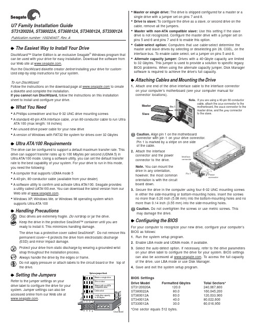
Interface connectorPower connectorU7 Family Installation GuideST3120020A, ST380022A, ST360012A, ST340012A, ST330012A Publication number: 100240407, Rev. AThe Easiest Way to Install Your DriveDiscWizard™ Starter Edition is an exclusive Seagate ® Windows program that can be used with your drive for easy installation. Download the software from our Web site at .Run the DiscWizard diskette creator before installing your drive for custom-ized step-by-step instructions for your system.To run DiscWizard:Follow the instructions on the download page at to create a diskette and complete the installation.If you cannot run DiscWizard, follow the instructions on this installation sheet to install and configure your drive.What You Need• A Phillips screwdriver and four 6-32 UNC drive mounting screws• A standard 40-pin ATA interface cable, or an 80-conductor cable to run UltraATA 100 (max length: 18 inches)• An unused drive power cable for your new drive• A version of Windows with FAT32 file system for drives over 32 GbytesUltra ATA/100 RequirementsThe drive can be configured to support a default maximum transfer rate. This drive can support transfer rates up to 100 Mbytes per second (UDMA 5) in Ultra ATA/100 mode. Using a software utility, you can set the default transfer rate to the best capability of your system. For your drive to run in this mode,you need the following:• A computer that supports UDMA mode 5• A 40-pin, 80-conductor cable (available from your dealer)• A software utility to confirm and activate Ultra ATA/100. Seagate providesa utility called UATA100.exe. You can download the latest version from our Web site at .• Windows XP, Windows Me, or Windows 98 operating system whichsupports Ultra ATA 100Disc drives are extremely fragile. Do not drop or jar the drive.Keep the drive in the protective SeaShell™ container until you are ready to install it. This minimizes handling damage.The drive has a protective cover called SeaShield ®. Do not remove this permanent cover—it protects the drive from electrostatic discharge (ESD) and minor impact damage.Protect your drive from static discharge by wearing a grounded wrist strap throughout the installation process.Always handle the drive by the edges or frame.Do not apply pressure or attach labels to the circuit board or the top of the drive.Setting the JumpersRefer to the jumper settings on your drive label to configure the drive for your system. Jumper settings can also be accessed online from our Web site at .SlaveIf you are using a 40-pin 80-conductorcable, attach the blue connector to the motherboard, the black connector to the master drive, and the grey connector to the slave. Options jumper block• Master or single drive: The drive is shipped configured for a master or asingle drive with a jumper set on pins 7 and 8.• Drive is slave: To configure the drive as a slave, or second drive on the cable, remove all the jumpers.• Master with non-ATA compatible slave: Use this setting if the slavedrive is not recognized. Configure the master drive with a jumper set on pins 5 and 6 and pins 7 and 8 to enable this option.• Cable-select option: Computers that use cable-select determine the master and slave drives by selecting or deselecting pin 28, CSEL, on the interface bus. To enable cable select, set a jumper on pins 5 and 6.• Alternate capacity jumper: Drives with a 40-Gbyte capacity are limitedto 32 Gbytes. This jumper is used to provide a solution to specific legacy BIOS problems. When using the alternate capacity jumper, Disk Manager software is required to achieve the drive’s full capacity.Attaching Cables and Mounting the Drive1.Attach one end of the drive interface cable to the interface connector on your computer’s motherboard (see your computer manual for connector locations).Caution. Align pin 1 on the motherboardconnector with pin 1 on your drive connector.Pin 1 is marked by a stripe on one side of the cable.2.Attach the interfaceconnector and the power connector to the drive.Note. You can mount the drive in any orientation,however, the most common orientation is with the circuit board down.3.Secure the drive in the computer using four 6-32 UNC mounting screws in either the side-mounting or bottom-mounting holes. Insert the screws no more than 0.20 inch (5.08 mm) into the bottom-mounting holes and no more than 0.14 inch (3.55 mm) into the side-mounting holes.Caution. Do not overtighten the screws or use metric screws. Thismay damage the drive.Configuring the BIOSFor your computer to recognize your new drive, configure your computer’s BIOS as follows:1.Run the system setup program.2.Enable LBA mode and UDMA mode, if available.3.Select the auto-detect option. If necessary, refer to the drive parameters on your drive label to configure the drive for your system. BIOS settings can also be accessed at . To access the full capacity of the drive, use LBA mode or use Disk Manager.4.Save and exit the system setup program.BIOS Settings Drive Model Formatted GbytesTotal Sectors*ST3120020A 120.0240,067,800ST380022A 80.0160,045,200ST360012A 60.0120,033,900ST340012A 40.080,022,600ST330012A30.060,016,950*One sector equals 512 bytes.Preparing the Drive with DiscWizardInstalling a Single DriveIf you are installing a single drive, we recommend using DiscWizard to automatically partition and format your drive. DiscWizard software is available at . During the download, the Diskette Creator creates a portable bootable diskette. To run DiscWizard:1.Insert your bootable DiscWizard diskette and follow the instructions.DiscWizard will guide you through the installation process.2.Boot your computer from the Windows operating system CD-ROM orfrom your system startup diskette with the Windows CD loaded. At the prompt, type setup.Installing a Slave DriveIf you are installing a second drive, or slave, to your system, use the DiscWizard software available at .Note. If you do not want to install your drive using either DiscWizard or Disk Manager, see “Standard Microsoft Installation” below to partition and format your drive.Standard Microsoft InstallationCaution.Partitioning or formatting a drive erases all data on it.Seagate assumes no liability if you erase your data.Drive PartitioningPartitioning divides the drive into sections or partitions that function as separate logical drives (labeled C,D,E, etc.). To partition your new drive:1.Insert a bootable startup diskette and restart your computer.2.Run fdisk and create a primary DOS partition.3.Mark the partition as active to make the partition bootable.Drive FormattingCaution. Use the correct drive letters to prevent formatting a drive that already contains data.1.At the A: prompt, type format x: where x is the letter of your first newpartition. Repeat the format process for all new partitions.2.Proceed to “Loading the Operating System” below.Loading the Operating SystemNote. The operating system needs to be installed on the master drive only. It is not required when adding a second drive.1.Boot your computer from your Windows operating system CD-ROM orfrom your system startup diskette with the Windows CD loaded.2.At the prompt, type setup and continue with the Windows setup.TroubleshootingIf your drive is not working properly, follow these troubleshooting steps.1.Does the drive spin up? A spinning drive produces a faint whine andclicking noise that begins when power is applied. If your drive does not spin, check that the power connector and interface cable are securely attached and the jumpers are installed correctly.2.Does the computer recognize the drive? Verify that the drive isenabled in the system CMOS or setup program. If not, select theautodetect option and enable it. If your drive has a problem, it may not be recognized by the system.3.Does FDISK detect the drive? Run the FDISK program located onyour Windows startup diskette. Type fdisk/status to verify that your hard drive is present.4.Does Scandisk find the drive defect-free? Scandisk is a utilitylocated on your Windows startup diskette that scans the drive fordefects. If defects are detected, this may be an indication of a problem.5.Why won’t the drive format to full capacity? Verify that your BIOShas autodetect and LBA mode enabled. Otherwise you may need to use Disk Manager to achieve the full capacity of your drive. Download the latest version from or find it on your CD.6.The computer hangs on startup. Verify that your system is ATA/100compatible with the UDMA mode setting. Some legacy BIOS causehangs on startup or other problems if not ATA/100 compatible. For more information, see the earlier section on the Ultra ATA/100 requirements. In addition, some legacy BIOS may cause a hang due to the large drive capacity. Consider using the alternate capacity jumper if it is available on your drive model.Use the alternate capacity jumper if your computer does not support higher capacity drives. The jumper will limit 40-Gbytes drives and larger to 32 Gbytes.Note.If these steps do not solve the problem, contact your dealer or visit to download SeaTools disc diagnosticssoftware and more troubleshooting advice.Seagate Support ServicesFor online information about Seagate products, visit ore-mailyourdiscquestionsto:***********************.If you need further help installing your drive, first consult your dealer. Dealers are familiar with their unique system configurations and can help you with system conflicts and other technical issues. If you need additional help, you can talk to a Seagate technical support specialist. Before calling, note your system configuration and drive model number.Africa+31-20-316-7222New Zealand0800-443988Australia1800-14-7201Norway800-113 91Austria0 800-20 12 90Poland00 800-311 12 38Belgium0 800-74 876Singapore800-1101-150Denmark80 88 12 66Spain900-98 31 24France0 800-90 90 52Sweden0 207 90 073Germany************Switzerland0 800-83 84 11Hong Kong800-90-0474T aiwan+886-2-2514-2237India1-600-33-1104Thailand001-800-11-0032165 Indonesia001-803-1-003-2165Turkey00 800-31 92 91 40Ireland 1 800-55 21 22United Kingdom************Italy800-790695USA/Canada/1-800-SEAGATE or Malaysia1-800-80-2335Latin America+1-405-936-1234Middle East+31-20-316-7222Other EuropeanNetherlands************Countries+ 31-20-316-7222 Warranty To determine the warranty status of your Seagate disc drive, contact your place of purchase or visit our Web site at for more information.RMA (Return Merchandise Authorization) Run SeaTools to diagnose your drive before requesting a return authorization. In addition, please verify that your drive is defective by following the troubleshooting checklist in this guide. Seagate offers comprehensive customer support for all Seagate drives worldwide. Seagate customer service centers are the only facilities authorized to service Seagate drives. Drive return procedures vary depending on geographical location and are subject to current International Trade Regulations.Shipping Your DriveCaution. Back up the data on your drive before shipping it. Seagate assumes no responsibility for data lost during shipping or drive repair. Shipping a drive in an unapproved container voids the warranty. Pack the drive with foam rubber only.Do not use peanuts, bubble wrap or newspapers.Keep your original box and packing materials for storing or shipping your drive. To preserve the warranty status of your drive, any product returned to Seagate must be properly packaged in the original box or a Seagate-approved container to prevent physical and electrical damage while in transit.Electromagnetic Compliance for the European Union This model complies with the European Union requirements of the Electromagnetic Compatibility Directive 89/336/EEC of 03 May 1989 as amended by Directive 92/31/EEC of 28 April 1992 and Directive 93/ 68/EEC of 22 July 1993. Compliance of this drive, as a system component, was confirmed with a test system. We cannot guarantee that your system will comply. The drive is not meant for external use (without properly designed enclosure, shielded I/O cable, etc.). Sicherheitsanleitung 1. Das Gerrät ist ein Einbaugerät, das für eine maximale Umgebungstemperatur von 55°C vorgesehen ist. 2. Zur Befestigung des Laufwerks werden 4 Schrauben 6-32 UNC-2A benötigt. Bei seitlicher Befestigung darf die maximale Länge der Schrauben im Chassis nicht mehr als 3,3 mm und bei Befestigung an der Unterseite nicht mehr als 5,08 mm betragen.3. Als Versorgungsspannugen werden benötigt: +5V ± 5% 0,6A; +12V ±% 0,8A (1,9A fur ca. 30 Sek. fur ± 10%)4. Die Versorgungsspannung muss SELV entsprechen.5. Alle Arbeiten auf dem Festplatte dürfen nur von Ausgebildetem Servicepersonal durchgeführt werden. Bitte entfernen Sie nicht die Aufschriftenschilder des Laufwerkes.6. Der Einbau des Laufwerkes muss den Anforderungen gemäss DIN IEC 950 VDE 0805/ 05.90 entspreche.© 2002 Seagate Technology LLC. All rights reserved.Publication Number: 100240407, Rev. A, Printed in USA, October 2002Seagate, Seagate Technology, and the Seagate logo are either registered trademarks or trademarks of Seagate Technology LLC. U7, DiscWizard, SeaShell and SeaShield are either registered trademarks or trademarks of Seagate Technology LLC. Other product names are registered trademarks or trademarks of their owners.。
新版photoshop cc正版免费下载安装及Camera Raw插件的设置教程

新版photoshop cc正版免费下载安装及Camera Raw插件的设置教程引言:很多漂亮图片,都是经过软件后期处理后呈现出来的。
就是由Photoshop这款功能强大的软件来完成的,Photoshop主要处理以像素所构成的数字图像。
其次Photoshop还有很多功能,比如在图像、图形、文字、视频等方面都有涉及。
接下来小编把photoshop的下载安装及Camera Raw插件的设置方法分享给大家,希望对大家有所帮助。
工具:电脑Photoshop安装包photoshop cc下载安装方法:一、打开浏览器在百度输入“photoshop cc”,可以选择任意一个点击进入下载。
如图所示:二、下载后还需按提示操作后才能把photoshop安装包下载到电脑上,一般都会自带了些第三方软的件会,需要把“ ”内的“√”去掉才不会自动安装到电脑。
如图所示:三、点击压缩包鼠标右键解压软件即可。
如图所示:四、点击解压好的文件夹,选择Setup.exe安装,需要先登录如果没账号的点击获取Adode ID。
如图所示:五、设置好账号后,点击注册,会自动跳转到安装程序界面,点击继续。
如图所示:六、在界面的上面可以看到安装的进度及剩余时间。
安装完成后,在桌面上找到photoshop图标,如果没有找到的需要在安装路径的文件夹内打开。
如图所示:七、在这一些会提示需要登录的界面,点击以后登录。
如图所示:八、然后软件就会出现一个试用7天的界面,因为我们的软件还没有破解,关闭软件,再返回到解压包里。
如图所示:九、打开“Amtemu.exe”,选择“adobe photoshop cc2015”,点击“Install”(电脑要链接上网络)。
如图所示:十、找到软件的安装目录,选择“amtlib.dll”打开,看到“Extract DLL”和“Extract INI”为OK,说明photoshop破解成功。
如图所示:十一、打开软件,我们需要设置Camera Raw插件,在菜单栏的“编辑”→“首选项”→“Camera Raw”。
Xmanager7安装破解激活与换机转移许可证教程详解

Xmanager7安装破解激活与换机转移许可证教程详解Xmanager是业界领先的PC X服务器,它允许您将X应⽤程序的能⼒带到⼀个Windows环境。
通过使⽤ Xmanager,安装在基于UNIX的远程机器上的X应⽤程序可以与Windows应⽤程序并排⽆缝地运⾏。
本篇⽂章主要为⼤家介绍Xmanager 7的安装、激活与换机转移许可证的⽅法。
注意:您在官⽹下载页下载的Xmanager仅为试⽤版,该版本⽆法激活,如您已购买软件请卸载试⽤版并在个⼈订单中⼼中下载安装安装包重新安装。
硬件要求:Intel® Pentium 或更快的CPU系统要求:Microsoft Windows® 10 / 8.1 / 8 / 7,Windows Terminal Service, Citrix MetaFrameXmanager 7(远程服务器管理) V7.0.0087 官⽅中⽂破解版(附补丁+安装⽅法)类型:服务器其它⼤⼩:106MB语⾔:简体中⽂时间:2021-11-03查看详情软件安装1. 双击下载好的Xmanager 7安装包,打开安装向导,选择“下⼀步”。
图1:Xmanager 7安装向导2.请您仔细阅读⽤户许可协议,同意请勾选“我同意许可证协议中的条款”,并选择“下⼀步”。
图2:许可证协议3.选择程序安装路径,默认在C盘,需要更改请选择“浏览”,完成请选择“下⼀步”。
图3:安装路径4.安装向导准备就绪,可以开始安装了,继续请选择“安装”。
图4:开始安装5.正式开始安装,该过程会持续⼏分钟,请耐⼼等待,不要关闭或重启电脑。
图5:Xmanager7安装中6.选择“完成”,完成安装程序。
图6:Xmanager7完成安装软件激活打开我们刚刚安装完成的Xmanager Power Suite 7⽂件夹,我们可以发现他把套件所包含应⽤的快捷⽅式都放在这⾥了。
图7:Xmanager7所含应⽤我们随便点开我们需要⽤到的应⽤,会显⽰“许可证尚未激活”,点击如下图中的“⽴即激活”按钮。
系统监控软件安装教程

系统监控软件安装教程系统监控软件是一种能够帮助用户监测、管理和维护计算机系统的工具。
它能够实时监测硬件和软件的运行状态,帮助用户及时发现并解决系统问题。
本文将向您介绍如何安装系统监控软件。
第一步:选择适合的系统监控软件在安装系统监控软件之前,您需要先选择一款适合您的需求和操作系统的软件。
常见的系统监控软件包括Zabbix、Nagios、PRTG等。
您可以根据自己的需求,在互联网上搜索相关软件的功能和特点,选择一款合适的软件。
第二步:下载系统监控软件在选择好了适合自己的系统监控软件之后,您可以在软件官方网站或者其他可靠的软件下载站下载软件的安装包。
请注意,一定要选择可信的下载来源,以免下载到含有病毒或恶意软件的安装包。
第三步:安装系统监控软件1. 双击下载的安装包文件,打开安装向导。
2. 在安装向导中,您可以选择安装路径、语言等选项。
默认选项通常是合适的,您可以根据自己的喜好进行个性化设置。
3. 点击“下一步”按钮,开始安装软件。
安装过程可能需要一些时间,请耐心等待。
4. 安装完成后,您可以选择是否运行软件。
如果您想立即开始使用软件,可以勾选“立即运行”选项,然后点击“完成”按钮。
第四步:配置系统监控软件1. 打开系统监控软件,并进行相关的配置。
不同的软件配置方式不同,您可以根据软件的提示进行配置。
一般来说,您需要配置监控服务器的IP地址、端口号等信息。
2. 配置完成后,您可以点击“测试连接”或类似按钮,测试与监控服务器的连接是否成功。
3. 如果连接成功,您可以开始添加需要监控的主机或设备。
在软件中选择“添加主机”或类似选项,填写主机的IP地址、名称等信息,然后保存设置。
4. 完成上述步骤后,系统监控软件将开始监控所添加的主机或设备,并实时显示相关监控数据。
第五步:优化系统监控软件设置为了更好地使用和管理系统监控软件,您可以进一步优化软件的设置。
例如,您可以设置监控的阈值,当系统指标超过设定的阈值时,软件会发出警报。
NEWCAM软件安装教程

THANKS FOR WATCHING
感谢您的观看
脚本自动化
通过脚本编写,实现自动化处理和批量操作。
插件扩展
利用第三方插件扩展软件功能,实现更多高 级功能。
协同工作
支持多人协同工作,共同完成大型项目的制 作和编辑。
05 软件更新与维护
软件更新
定期检查更新
建议用户定期检查Newcam软件 的更新,以确保软件始终保持最 新状态,并获得最新的功能和安 全补丁。
问题2
安装后无法打开软件。
问题3
软件功能异常或崩溃。
解决方案
尝试更新软件至最新版本,或联系软件技术支持获取帮 助。
02 软件设置与配置
初始设置
软件安装
首先,需要从官方网站下载Newcam 软件,并按照指示完成安装。确保选 择正确的安装路径,并遵循默认设置 或自定义设置。
启动软件
安装完成后,双击桌面图标或从开始 菜单启动Newcam软件。首次启动时, 软件将进行初始化设置。
首先需要从官方网站下载 Newcam软件,并按照提
示进行安装。
创建项目
在软件中创建一个新的项 目,选择合适的项目类型
和设置。
编辑素材
对导入的素材进行编辑, 包括裁剪、调整颜色、添
加特效等。
打开软件
安装完成后,打开 Newcam软件。
导入素材
将需要处理的图片、视频 等素材导入到项目中。
导出项目
完成编辑后,将项目导出 为所需的格式,如MP4、
检查是否有其他软件与Newcam 快捷键冲突,如有冲突,可更改 其他快捷键或禁用冲突软件。
03 软件功能介绍
主要功能
视频剪辑
支持导入多种格式的视频文件 ,进行剪辑、拼接、裁剪等操
关于proe和catia的安装

关于PROE和达索CATIA的安装安装PROE1、首先将安装包拷到一个文件夹中,文件夹名要设为英文,比如在D盘新建soft文件夹,然后解压。
2、打开解压后的WF5_Win32_crk文件夹,找到license.dat文件,并在C盘下新建一个文件夹,文件夹命名为英文,比如crack5,将license.dat文件放在该文件夹下。
3、将license文件用记事本打开,找到类似这样的语句#REPLACE ALL00-00-00-00-00-00 WITH YOURSELF PTC_HOST_ID,一般在第三行,将其中的00-00-00-00-00-00改成你本机的物理地址,该文件中所有的。
00-00-00-00-00-00都要改成你本机的物理地址,用记事本中的替换命令即可完成。
(找到物理地址的方法:在开始—运行中输入cmd,然后回车,然后在DOS命令提示符上输入ipconfig /all命令,回车即可看到你的物理地址,如下图所示。
)替换命令如下所示:查找物理地址如下:4、在解压后的PROENGINEER WILDFIRE 5.0 M050 FORWINDOWS7&XP&VISTA-32BIT文件夹中找到setup文件,双击打开,如图所示,就可开始安装。
5、点击下一步,点击我接受协议,再点击下一步,看到如下图所示的界面,选择第二项,Pro/ENGINEER选项,可看到如下图所示的安装界面点击下一步。
6、选择公制。
如下图所示:点击下一步。
7、点击添加许可证,选择第三项锁定的许可证文件,选择许可证路径为刚刚存放license.dat文件的路径,如上面存放路径,我选取的许可证路径如图所示:点击确定,再点击下一步。
8、如果是PD部门(产品开发部),则在此界面的启动目录项要设置为D:\plmproe,后面还需在该文件夹下放置一些文件,这些文件可以找产品开发部主管梅自远师傅,他会给你安装。
如果是其他部门,按照默认路径点击下一步即可,没有plmproe文件夹则会提示重新新建一个。
Mac苹果10.8山狮系统安装教程
这里用硬盘安装,变色龙引导的方法,只推荐原版一、安装Mac OS X Mountain Lion正式版需要的软件与文件01.Java虚拟机02.hfsexplorer.0.21(过滤镜像)03.Leopard hd installhelper v0.3(硬盘安装助手, Made in China)04.macdrive_8.0.7.38_en_setup(打开黑苹果盘) (自己注册破解) 05.OSInstall(替换文件) 下载对应版本06.变色龙Chameleon Install,要生成org.chameleon.boot.plist文件然后加在Extra文件夹下。
(要使用合适的版本)07InstallESD.dmg专业术语:S/L/E:系统盘或者安装盘里面,win下查看时为system—Library—Extensions,mac下显示为:系统—资源库—ExtensionsE/E:系统盘或者安装盘里面,Extra——Extensions驱动问题:Intel HD3000可以免驱:1000版本之后的变色龙+smbios 机型设置为MBP8.1+系统自带驱动=完美驱动HD3000声卡用万用声卡驱动驱动安装:详见驱动安装二、安装MAC OS系统需求01. 主板:BIOS开启AHCI (最好在安装Lion之前把主板的AHCI功能驱动做好)因为有些电脑还起AHCI功能后就进不了原来的系统了,如果真进不了不用怕,再进BIOS改回IDE就行了02.CUP:Intel I 系列一般能直接安装,AMD的需要破解内核三、开始制作MAC OSX Lion的安装硬盘(所有操作都在Win7下进行)(XP用DiskGenius或其他硬盘工具分区)原理:在Win 7透过BaseSystem.dmg取得Mac磁盘工具恢复正确的安装盘。
操作步骤一①建立2个分区5G、50G(全都不要格式化),建议分好区以后用DiskG软件把这两个盘修改参数为AF全局步骤:一、先大盘50G制作小盘5G二、后小盘5G安装大盘50G开始制作大盘①先用HFSExplorer-0.21提取InstallESD.dmg里面的BaseSystem.dmg、mach_kernel及/Packages文件夹,再用HFSExplorer-0.21打开BaseSystem.dmg文件。
Xmanager安装教程
Xmanager安装教程Xmanager是一款综合服务Linux/UNIX的管理工具,安装之后可以轻松的将原本枯燥的代码操作转为图形界面操作,可以更直观的操控远程。
安装教程详细步骤如下:1. 首先在网站中下载xmanager软件图1:xmanager安装向导2. 双击软件进行安装,会弹出“xmanager安装程序正在准备installshield wizard,它将引导您完成剩余的安装过程。
请稍候”,大概需要等待2、3秒时间图2:向导提示3. 完成后页面会出现欢迎使用xmanager安装导向,如需继续安装,请点击“下一步”的提示,我们就提示点击“下一步”图3:xmanager安装协议4、在弹出的“许可证协议”中选择“我接受许可证协议中的条款”,如果需要保存或更仔细查看协议的可以选择“打印”,没有异议的请点击“下一步”图4:客户信息填写图5:是否使用试用版5、填写客户信息,以及产品密钥,如果还没有购买可以在官网购买xmanager,如果想要先试用一下,可以不输入密钥,选择使用评估版,完成后点击“下一步”图6:安装位置选择6、选择安装目的地文件夹,选择好之后,依旧点击“下一步”图7:安装类型选择7、选择安装的类型,主要有典型、压缩、定制三种类型,典型就是大多数用户使用的选项;压缩就是选择最少的选项进行安装;定制就是用户自己选择需要安装的选项;一般建议选择典型,完成后点击“下一步”图8:选择程序文件夹8、接着选择程序文件夹,点击“下一步”图9:选择安装语言9、选择语言,可以选择简体中文版或英语版,如果以后在软件使用过程中如果需要变更,可以在工具菜单中更改。
图10:安装状态10、而后,软件会弹出安装状态,然后耐心等上一会会图11:安装完成11、xmanager就完成安装了。
ANSYS安装教程
ANSYS 14.5.7安装全过程(2021-08-19 15:43:46)▼标签:杂谈不太明白为什么总有朋友在ANSYS安装上纠结。
按照我个人的经历,ANSYS自11.0版本之后,其安装过程极为简单,不应该存在安装方面的问题。
这里以ANSYS14.5.7为例详细描述软件安装过程。
由于本人使用的是D版,故文中会涉及一局部PJ方面的步骤,望官方勿扰,各位看官假设口袋充实的话还是多支持正版。
再次声明:D版软件仅用于学习,请勿用于商业用途。
〔这里有说废话的嫌疑,一般来说,正版用户可以享受代理商上门安装效劳。
呵呵〕1、准备工作在进展安装工作之前,需要进展一些准备工作:〔1〕准备ANSYS软件。
这个毋庸置疑。
ANSYS14.5.7可以在互联网上很容易搜索并下载得到。
当然D版也有很多版本,本文使用MAGNiTUDE版本。
〔2〕虚拟光驱软件。
这个网络上随便下载一款即可。
本文使用winmount作为虚拟光驱软件。
〔3〕预留大约20G硬盘空间。
2、安装必须文件翻开下载的ANSYS14.5.7文件夹,包含两个主要文件ANSYS1457_WINX64_disk1.ISO及ANSYS1457_WINX64_disk1.ISO。
利用虚拟光驱加载DISK1。
需要注意的是,这里务必使用虚拟光驱或刻录光盘,请勿解压。
文件夹中内容如下列图所示,鼠标双击InstallPreReqs.exe文件进展必要程序安装。
3、安装ANSYS鼠标双击setup.exe文件,进入ANSYS安装过程。
〔注意:假设为Win7以上版本,为防止不必要的麻烦,可选择管理员模式安装〕弹出如上图所示对话框,如下图。
选择【I nstall ANSYS Products】进展安装。
对于其他选项:〔1〕EKM Server。
安装ANSYS EKM效劳器,个人用户很少用到。
〔2〕MPI。
安装MPI协议,主要用于并行计算,不安装的话可以使用ANSYS默认并行协议。
可在后面选择性安装。
Snap-on ECO Xtreme 安装说明书
INSTALLATION OVERVIEW:______________________________________________The Installation Procedure listed is for the Snap-on ECO Xtreme™ (EEAC318A). The unit is shipped asa fully assembled unit, with the exception for the items listed in the Parts & Accessories.PLEASE READ THESE INSTRUCTIONS COMPLETELY BEFORE SETTING UP UNITPARTS & ACCESSORIES:________________________________________________PART NUMBER DESCRIPTION QTY1-15080 Adapter, Low Side 11-27180 Adapter, Vehicle, High Side 11-27280 Adapter, Vehicle, Low Side 11-05585A Bottle, Disposable 8oz. 15-1145 Plastic tie wrap 1Certificate 1 8-1163 Equipment8-1263 Technician Certificate 1EAA0275L05A Recovery Tank Assembly (R-134a) 1EAH0001C01A Red Hose 1Hose 1EAH0001C02A BlueTEEAC318A0 Installation Instructions 1Manual 1 ZEEAC318A User’sREQUIRED TOOLS:_____________________________________________________•Safety Goggles•R-134a Virgin Tank (Supplied by Customer)•GlovesPARTS & ACCESSORIES SETUP__________________________________________1. Remove the Blue and Red Hoses from the box, along with the plastic-tie-wrap. Remember toOIL the seals on each end of the hoses.2. Connect the high (red) and low (blue) couplers to their respective hoses. Rotate coupler knobsfully CCW (closed).3. Route both hoses in-between the master filter bracket and the hose that connects to the filter.4. Attach other end of the (red) hose to upper, red labeled (high side) port on the back panel of theEco Xtreme™ unit.5. Attach other end of the blue hose to lower, blue labeled (low side) port on the back panel of theEco Xtreme™ unit.6. The plastic-tie wrap will be used later, to secure the hoses to the master filter bracket. (Page 4,line 12).7. Install plastic oil bottle (1-05585A) to the white cap mounted in the front of the unit.8. Remove the User's Manual, MAC Form/Certification, Product Registration Form, and WarrantyRegistration from the box. Hand these items to the Owner or Manager.9. Remove Recovery Tank (EAA0275L05A) from its box. Remove cardboard wrap from RecoveryTank and set on floor.PREPARING RECOVERY TANK:__________________________________________1. Referring to FIGURE 1, open the BLUE valve onRecovery Tank to release ALL COMPRESSED AIR. 2. Gently set the Recovery Tank on the scale. 3. Place the strap around the recovery tank.4. Position the Temperature Probe between the tank andthe strap. 5. Install the supplied tank adapter 1-15080 on the Low(blue) side of the recovery tank. 6. Attach the blue vehicle hose w/adapter to the Low sideof the tank. 7. Plug AC Cord to a proper 115VAC outlet. And turn-onthe unit by the rear panel switch.NOTE: In the unlikely event, the LCD screen isunreadable upon power up, adjust LCD contrast. Refer to the users manual for contrast adjustment.8. Press the Down arrow, Arrow on display will be pointing to “VACUUM”.a. Press <ENTER>.b. Press the Down arrow until desired amount of vacuum time is displayed.c. Turn the front panel low panel valve to VACUUM.d. Press Start button, vacuum pump should turn ON in about 5 seconds. 9. The low side gauge shows vacuum increasing.10. Monitor low side gauge until a minimum of 25 inches has been reached.11. Once completed, close the Recovery Tank valve (BLUE). Close the R-134a Coupler. 12. Press EXIT button. The pump will shut-off. 13. Remove the blue service hose from the tank.NOTE: Remove the R-134a tank adapter, (1-15080) and place in the storage tray. 14. the yellow hose to the tank purge port. See figure to the right. 15. Identify the blue hose leading from the bottom of the unit.16. If you are going to continue with Gravity refrigerant transfer(found on page 4), leave the red hose disconnected.Otherwise identify the red hose leading from the bottom ofthe unit. Connect hose with the anti-blowback valve to the red (vapor) valve.17. Open both red and blue valves on tank unless continuing with Gravity Transfer method.18. If you are going to continue with Gravity refrigerant transfer, do not attach plastic –tie. Using theplastic-tie wrap (5-1145) route the tie through the hole in the bracket, wrap around the hoses and tie.Refer to the users manual for pre-charging tanks. Refer to next page for first time fast charge.INSTALLATION COMPLETEFIGURE 1 RECOVERY TANKPRE-CHARGING RECOVERY TANKS USING GRAVITY METHOD:NOTE: THIS PROCEDURE IS USED TO SETUP THE UNIT FOR CHARGING. RECOVERY TANKSHOULD HAVE AT LEAST A 25” VACUUM. THIS PROCEDURE IS DONE WHEN RECOVERY TANK IS ON THE SCALE1. Plug unit in and turn on, go into Charge screen tomonitor tank weight.2. Be sure Recovery Tank valves (B) are closed andtank is in vacuum on scale. Refer to FIGURE 2. 3. Disconnect the Red hose from the Recovery Tank. 4. Disconnect and Re-Oil both the seals on blue hose(C). Connect the one side of the blue Hose w/ adapter (1-15080) to the Virgin Tank (A). 5. Connect the other end of the blue Hose to the RedValve on the Recovery Tank (B). 6. Open the Red Valve on the Recovery Tank. 7. Raise the Virgin Tank to a higher level than theRecovery Tank. Invert the Virgin Tank (A) and open valve. 8. Gravity and vacuum will transfer the liquid refrigerantto the Recovery Tank faster than recovering it.NOTE: DO NOT OVER CHARGE TANK. THESAFE AMOUNT TO CHARGE IS AROUND 15 LBS. 9. After the desired amount of refrigerant has beentransferred, close valves on Virgin Tank first, pause to allow refrigerant to flow into tank, then close recovery tank valve. Set Virgin Tank on ground upright. 10. Disconnect blue hose, and adapter from both Tanks. 11. Re-Oil seals on anti-blow back valve on the RedHose from unit and connect to Recovery Tank. Open both Recovery Tank valves.12. Re-Oil seals on red and blue hoses. To connect thehoses, route both in-between the master filter bracket and the hose that connects to the filter. Connect the open end of the Blue hose to the Low side bulkhead fitting and Red Hose to the high side bulkhead fitting. Using the plastic-tie wrap route the tie through the hole in the bracket, wrap around the hoses and tie. 13. Unit is ready to recover and charge refrigerant.FIGURE 2 CHARGING TANKREMEMBER TO OIL O-RINGS AND SEALS WHEN ATTACHING HOSES OR FITTINGS。
- 1、下载文档前请自行甄别文档内容的完整性,平台不提供额外的编辑、内容补充、找答案等附加服务。
- 2、"仅部分预览"的文档,不可在线预览部分如存在完整性等问题,可反馈申请退款(可完整预览的文档不适用该条件!)。
- 3、如文档侵犯您的权益,请联系客服反馈,我们会尽快为您处理(人工客服工作时间:9:00-18:30)。
XTereme安装步骤:
1、安装好VC++6.0 和对应的SP6补丁包;
2、打开CodeTock_XTP\Keygen文件夹下的keygen.exe,如图1所示
图1
3、打开后在Products选项栏选择:XtremeTookitPro点击Generate按钮生成序
列码;复制生成的序列码
图2
4、在CodeTock_XTP目录下双击setup.exe
图3 5、点击next
图4
6、选择I accept the agreement 点击Next
图5
7、将图2生成的序列码OA5B4-39893-56D95-50320-48038 拷贝到编辑框中;
图6
8、选择文件的安装目录:默认是C盘,安装目录可以修改,此处将安装目录设
为D:\Program Files\Codejock Software\MFC\XtremeToolkitPro v15.0.1,设置好
后,点击Next
图7 9、勾选所有项,按Next
图8 10、点击Next
图9 11、点击Install
图10 12、等待安装
图11 13、安装成功后,单击Next
图12 14、勾选所有项,点击Next
图13
15、勾选当前使用的编译环境,针对VC++6.0 SP6 编译环境,这里勾选Visual
C++ Version 6,点击Next
图14
16、勾选所有项,点击Next;
图15
17、针对VC++6.0 SP6,在VC++6.0安装包VC98\MFC\LIB目录下拷贝所有文
件名含MFC的.Lib文件
图16
18、将上面拷贝的文件粘贴到VC++6.0安装目录
\Program Files\Microsoft Visual Studio\VC98\MFC\Lib目录下;
图17
19、在VC++6.0安装包VC98\DEBUG文件夹下拷贝所有文件名包含MFC
的.DLL文件;
图18
20、将上面拷贝的文件复制到WINDOWS\system32目录下;
图19
21、等待biuldingLibarary
图20
图21
这个时间会比较长,liabaray Building完后就安装成功了。