fault calculation
ShortCircuit

Simple Methods for Calculating Short Circuit CurrentWithout a ComputerBy Dennis McKeown, PEGE Senior System Application EngineerA Short Circuit analysis is used to determine the magnitude of short circuit current the system is capable of producing and compares that magnitude with the interrupting rating of the overcurrent protective devices (OCPD). Since the interrupting ratings are based by the standards, the methods used in conducting a short circuit analysis must conform to the procedures which the standard making organizations specify for this purpose. In the United States, the America National Standards Institute (ANSI) publishes both the standards for equipment and the application guides, which describes the calculation methods.Short circuit currents impose the most serious general hazard to power distribution system components and are the prime concerns in developing and applying protection systems. Fortunately, short circuit currents are relatively easy to calculate. The application of three or four fundamental concepts of circuit analysis will derive the basic nature of short circuit currents. These concepts will be stated and utilized in a step-by-step development.The three phase bolted short circuit currents are the basic reference quantities in a system study. In all cases, knowledge of the three phase bolted fault value is wanted and needs to be singled out for independent treatment. This will set the pattern to be used in other cases.A device that interrupts short circuit current, is a device connected into an electric circuit to provide protection against excessive damage when a short circuit occurs. It provides this protection by automatically interrupting the large value of current flow, so the device should be rated to interrupt and stop the flow of fault current without damage to the overcurrent protection device. The OCPD will also provide automatic interruption of overload currents.Listed here are reference values that will be needed in the calculation of fault current. Impedance Values for Three phase transformersHV Rating 2.4KV – 13.8KV 300 – 500KVA Not less than 4.5%HV Rating 2.4KV – 13.8KV 750 – 2500KVA 5.75%General Purpose less then 600V 15 – 1000KVA 3% to 5.75%Reactance Values for Induction and Synchronous MachineX” SubtransientSalient pole Gen 12 pole 0.1614 pole 0.21Synchronous motor 6 pole 0.158-14 pole 0.20Induction motor above 600V 0.17Induction motor below 600V 0.25TRANSFORMER FAULT CURRENTCalculating the Short Circuit Current when there is a Transformer in the circuit. Every transformer has “ %” impedance value stamped on the nameplate. Why is it stamped? It is stamped because it is a tested value after the transformer has been manufactured. The test is as follows: A voltmeter is connected to the primary of the transformer and the secondary 3-Phase windings are bolted together with an ampere meter to read the value of current flowing in the 3-Phase bolted fault on the secondary. The voltage is brought up in steps until the secondary full load current is reached on the ampere meter connected on the transformer secondary.So what does this mean for a 1000KVA 13.8KV – 480Y/277V.First you will need to know the transformer Full Load AmpsFull Load Ampere = KVA / 1.73 x L-L KVFLA = 1000 / 1.732 x 0.48FLA = 1,202.85The 1000KVA 480V secondary full load ampere is 1,202A.When the secondary ampere meter reads 1,202A and the primary Voltage Meter reads 793.5V. The percent of impedance value is 793.5 / 13800 = 0.0575. Therefore;% Z = 0.0575 x 100 = 5.75%This shows that if there was a 3-Phase Bolted fault on the secondary of the transformer then the maximum fault current that could flow through the transformer would be the ratio of 100 / 5.75 times the FLA of the transformer, or 17.39 x the FLA = 20,903ABased on the infinite source method at the primary of the transformer. A quick calculation for the Maximum Fault Current at the transformer secondary terminals is FC = FLA / %PU Z FC = 1202 / 0.0575 = 20,904AThis quick calculation can help you determine the fault current on the secondary of a transformer for the purpose of selecting the correct overcurrent protective devices that can interrupt the available fault current. The main breaker that is to be installed in the circuit on the secondary of the transformer has to have a KA Interrupting Rating greater then 21,000A. Be aware that feeder breakers should include the estimated motor contribution too. If the actual connected motors are not known, then assume the contribution to be 4 x FLA of the transformer. Therefore, in this case the feeders would be sized at 20.904 + (4 x 1202 = 25,712 AmpsGENERATOR FAULT CURRENTGenerator fault current differs from a Transformer. Below, we will walk through a 1000KVA example.800KW 0.8% PF 1000KVA 480V 1,202FLAKVA = KW / PFKVA = 800 / .8KVA = 1000FLA = KVA / 1.732 x L-L VoltsFLA = 1000 / 1.732 x 0.48FLA = 1,202(As listed in the table for generator subtransient X” values is 0.16)FC = FLA / X”FC = 1202 / 0.16FC = 7,513ASo, the fault current of a 1000KVA Generator is a lot less then a 1000KVA transformer. The reason is the impedance value at the transformer and Generator reactance values are very different. Transformer 5.75% vs. a Generator 16%SYSTEM FAULT CURRENTBelow is a quick way to get a MVA calculated value. The MVA method is fast and simple as compared to the per unit or ohmic methods. There is no need to convert to an MVA base or worry about voltage levels. This is a useful method to obtain an estimated value of fault current. The elements have to be converted to an MVA value and then the circuit is converted to admittance values.Utility MVA at the Primary of the TransformerMVAsc = 500MVATransformer Data13.8KV - 480Y/277V1000KVA Transformer Z = 5.75%MVA Value1000KVA / 1000 = 1 MVAMVA Value = 1MVA / Z pu = 1MVA / .0575 = 17.39 MVAUse the admittance method to calculate Fault Current1 / Utility MVA + 1 / Trans MVA = 1 / MVAsc1 / 500 + 1 / 17.39 = 1 / MVAsc0.002 + 0.06 = 1/ MVAscMVAsc = 1 / (0.002 + 0.06)MVAsc = 16.129FC at 480V = MVAsc / (1.73 x 0.48)FC = 16.129 / 0.8304FC = 19.423KAFC = 19, 423 AThe 480V Fault Current Value at the secondary of the 1000KVA transformer based on an Infinite Utility Source at the Primary of the transformer as calculated in the Transformer Fault Current section in this article is 20,904AThe 480V Fault Current Value at the secondary of the 1000KVA transformer based on a 500MVA Utility Source at the Primary of the transformer as calculated in the System Fault Current section in this article is 19,432AThe 480V Fault Current Value at the secondary of the 1000KVA transformer based on a 250MVA Utility Source at the Primary of the transformer the calculated value is 18,790AWhen the cable and its length is added to the circuit the fault current in a 480V system will decrease to a smaller value. To add cable into your calculation use the formula. Cable MVA Value MVAsc = KV2 / Z cable. Use the cable X & R values to calculate the Z value then add to the Admittance calculation as shown in this article.The conclusion is that you need to know the fault current value in a system to select and install the correct Overcurrent Protective Devices (OCPD). The available FC will be reduced as shown in the calculations when the fault current value at the primary of the transformer is reduced. If the infinite method is applied when calculating fault current and 4 x FLA is added for motor contributions, then the fault current value that is obtained will be very conservative. This means the calculated value in reality will never be reached, so you reduce any potential overcurrent protection device failures due to fault current.。
法律英语常用词汇和句型总结
常用术语总结一、基本概念及用法债权人:obligee债务人:obligor一方:one party对方\相对人:the other party;善意相对人:the other party in good faith债权:creditor’s right; right to performance; right债务/义务: obligation标的物:subject matter责任:liability要约:offer;承诺:acceptance;要约邀请:invitation to offer;要约人:offeror受要约人:offeree收件人:recipient代理人:agent被代理人/本人:principle行为人:person performing (such) act代理权:agency authority应当:shall可以:may不能:may not不正当:improperly有权做. . .:may; is entitled to do履行义务:perform obligation, render performance订立合同:enter into a contract; conclude a contract; form a contract带来损失:cause loss to . . .损害利益:harm somebody’s interest赔偿损失:indemnify the other party for its loss由某人承担费用:expenses shall be borne by sb.承担损害赔偿责任:be liable for damages各自承担相应的责任:bear their respective liabilities accordingly要求承担违约责任:hold . . . liable for breach of contract享有权利、承担义务:assume right and obligation二、各个条文中的术语合同订立采取. . .方式: a contract is concluded by the exchange of. . .(e.g. by the exchange of an offer and an acceptance; by the exchange of electronic messages). . .的意思表示:manifestation of intention to do something做出表示:manifest his intention (to do)接受履行:accept the performance订立合同时:in the course of concluding/ negotiating a contract; at the time of its conclusion 符合...规定:meet the requirement of . . .承诺的撤回:withdrawal of acceptance书面形式:in writing合同书形式:memorandum of contract具有本法. . .条规定的情形:fall into any of the circumstances set forth in Article. . .撤回:withdraw; 撤销:cancel拒绝追认:decline; 拒绝履行:reject受约束:be bound;is binding upon somebody表明:indicate价目表:price list拍卖公告:announcement of auction招标公告:call for tender招股说明书:prospectus商业广告:commercial advertisement数据电文:electronic message指定特定系统:designate a specific system快速通讯方式:instantaneous communication device国家指令性任务或国家订货任务:state mandatory plan or state purchase order根据需要/要求:in light of its requirement格式条款:standard terms条款:provision提请注意义务:duty to call attention应. . .要求,做. . .:do something upon the request of . . .与对方协商:negotiate with the other party预先拟定:prepare in advance重复使用:repeated use提供格式条款一方:the party supplying standard terms免除或限制责任:exclude or limit liability加重对方责任:increase the liabilities of the other party排除对方主要权利:deprive the other party of material rights合理的方式:in a reasonable manner对格式条款的理解:construction of standard term通常理解:common sense不一致:discrepancy between… and …解释:interpret缔约过失责任:pre-contract liabilities恶意磋商:negotiate in bad faith以. . .名义:under the pretext of隐瞒与. . .有关的重要事实:conceal material facts relating to . . .提供虚假情况:supply false information商业秘密:trade secret泄露或不正当使用商业秘密:disclose or improperly use trade secret在订立合同的过程中获悉:become aware of in the course of negotiating a contract生效条件:conditions precedent解除条件:conditions subsequent阻止/促成条件成立:impair/facility satisfaction of a condition对合同的效力约定附条件:prescribe that the effectiveness of a contract be subject to certain conditions附生效/解除条件的合同:a contract subject to condition precedent/subsequent条件成立:condition is satisfied附期限的合同:contract term生效/失效期限:a time of commencement/expiration限制民事行为能力人:a person with limited capacity for civil act法定代理人:legal agent追认:ratify纯获利益的合同:a contract from which such person accrues benefits only与其年龄、智力、精神健康状况相适应:be appropriate for his age, intelligence, mental health催告法定代理人在一个月内予以追认:demand legal agent to ratify the contract within one month视为拒绝追认:is deemed to decline ratify the contract撤销的权利:somebody is entitled to cancel. . .以通知的方式做出:be effected by notification以. . .的名义:on one’s behalf没有代理权:lack agency authority超越代理权:act beyond his agency authority代理权终止:agency authority is extinguished请求人民法院或仲裁机构变更或撤销:petition the People’s court or an arbitration institution for amendment or cancellation重大误解:material mistake显失公平:grossly unconscionable欺诈:fraud胁迫:duress乘人之危:take advantage of the other party’s hardship真实意思:true intention受损害方:aggrieved party合同无效、被撤销或者终止:invalidity, cancellation or discharge of a contract不影响. . .条款的效力:not impair the validity of the contract provision concerning. . .争议解决方法:the method of dispute resolution返还财产:make restitution of property过错方:the party at fault折价补偿:allowance be made in money based on the value of the property在合同约定的交付期间:during the prescribed period of delivery交付时的价格:price of delivery迟延交付标的物/提取标的物/付款:delay in delivering the subject matter; delay in taking delivery; delay in making payment同时履行: simultaneous performance互负债务:owe performance toward each other没有先后履行顺序:there is no order of performance履行不符合约定:render non-conforming performance拒绝其相应的履行要求: reject its corresponding requirement for performance部分履行:partial performance债务人部分履行给债权人增加的费用:additional expenses incurred by obligee due to obligor’s partial performance代位权:subrogation怠于行使到期债权:delay in exercising its creditor’s right that was due专属于. . .人本身:exclusively personal to somebody转让债权:assign a right受让人取得与债权有关的从权利:assignee assumes any incidental right associated with the obligee’s right让与人与受让人:assignor, assignee接到. . . 通知:upon receipt of notice of assignment债务人可以向受让人主张抵销:the obligor may avail itself of any set-off against the assignee对某人享有债权: have right to performance by/against somebody合并/分立:a party has effected combination/division合并/分立后的法人:legal person resulting from combination/division行使合同权利,履行合同义务:assume the rights and obligations享有连带债权,承担连带债务:jointly and severally assume the rights and obligations合同解除:terminate合同终止:discharge债务互相抵销:obligations were set off against each other将标的物提存:place the subject matter in escrow免除债务:release the obligor from performance毁损、灭失的风险:the risk of damage or loss孳息:fruits of subject matter违约责任:liabilities for breach of contract履行合同义务:perform obligations under a contract符合约定的履行合同义务:perform obligations in accordance with the contract; render conforming performance继续履行:specific performance采取补救措施:cure of non-conforming performance赔偿损失:payment of damages预期违约:anticipatory breach明确表示:expressly state行为表明:indicate by conduct违约金:liquidated damage一定数额:a certain sum/amount of …根据违约情况:in the light of degree of breach因违约产生的损失赔偿额的计算方法:a method for calculation of damages for the loss resulting from a party’s breach.适当减少:decrease the amount as appropriate公平原则:the principle of fairness诚实信用原则:the principle of good faith三、“效力”的词汇. . .的效力:effectiveness/validity of . . .e.g. effectiveness of contract/offer生效:become effective失效:extinguish有效:valid无效:invalid四、时间的词汇到达时间:time of arrival承诺期限:the period for acceptance信件载明的日期或电报交发之日:date shown on the letter or the date on which the telegram is handed in for dispatch邮戳日期:the posting date stamped on the envelop超过承诺期间:after expiration of the period for acceptance履行期限:time of performance. . .期间自…开始计算:the period for. . . commences on the date when. . ./once . . .五、常用句型:●A符合B情况的,视为C:A is deemed as C, if B.●表示假设,用”where” or ”if”●如果是个长句子,内容为:在一个大前提A下,又有几个不同的条件(B、C),每个条件下的结果(D是B的结果,E是C的结果)都不同。
软弱下卧层验算
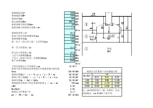
基础底面长L=
基础底面宽B=
基础高度h=
轴力标准值Fk=
地基承载力特征值
fak=地基承载力深度修正系数ηd=
基础砼容重γc=
软弱下卧层顶面埋置深度dz=
基础埋置深度d=
第一层土(持力层上面)土层厚度d1=
第一层土的重度γ1=
持力层土的重度γ2=
上层土压缩模量Es1=
下层土(软弱下卧层)压缩模量Es2=
地下水埋深dw=
下卧层顶面以上平均重度γm=
软弱下卧层顶面处经深度修正后地基承载力特征值faz=186.60kPa 基础自重Gk1= γ c * Vc =γ c * L * B * h=60.00kN 基础上的土重Gk2 = γ 1 * L * B * ( d - h)=28.80kN 基础自重Gk = Gk1 + Gk2=
88.80kN 基础底面至软弱下卧层顶面的距离 z = dz - d=700mm z/B=
0.35Es1/Es2=
2.00地基压力扩散角θ=
11.2°pk = (Fk + Gk) / A=
267.20kPa pc = γ 1 * d1 + γ 2 * (d - d1)=
18.00kPa pz=L*B*(pk-pc)/[(B+2*z*tan θ)*(L+2*z*tan θ)]=192.22kPa pcz = γm * dz=
30.60kPa pz + pcz =222.82>faz=186.60kpa 未通过。
新型串联电弧模型与特性分析
电工电气 (20 7 No. 2)作者简介:王建鹏(1989- ),男,工程师,硕士,主要从事变电检修工作。
新型串联电弧模型与特性分析王建鹏,韩浩(国网山东省电力公司寿光市供电公司,山东 寿光 262700)摘 要:以电路理论为基础,对RLR h 串联电路进行分析计算,提出一种以电弧电流为输出的新型电弧数学模型。
此模型以电弧电阻为变量,将电弧电阻看成时间的周期函数,并对电弧电阻进行分区域处理,给出了各区域电弧电阻的变化规律与数学表达式。
应用新模型进行计算,并将计算结果与Cassie 电弧模型和Stokes 电弧模型仿真结果进行对比,验证了新型电弧模型优于Cassie 电弧模型和Stokes 电弧模型,研究可为串联故障电弧的诊断提供可靠的理论依据。
关键词:电弧模型;电弧电阻;串联;特性分析中图分类号:TM501+.2 文献标识码:A 文章编号:1007-3175(2017)12-0033-04Abstract: Based on the circuit theory, this paper carried out analysis and calculation for the RLR h series circuit and proposed a kind of new type of arc mathematical model with arc current output. This model regarded the arc resistance as the variable, which was the periodic function of time. The arc resistance was carried out regional treatment. This paper gave the variation law and the mathematical expression of each regional resistance. This paper calculated the new type of model and the calculation result was compared with Cassie arc model and Stokes arc model to show excellent agreement. It is verified that the new arc model is better than the Cassie arc model and the Stokes arc model, which provides the reliable theoretical basis for the diagnosis of series fault arc. Key words: arc model; arc resistance; series circuit; characteristic analysisWANG Jian-peng, HAN Hao(Shouguang City Power Supply Company, State Grid Shandong Electric Power Company, Shouguang 2 2700, China )New Type of Series Arc Model and Characteristic Analysis0 引言故障电弧多由线路老化或接触不良等原因引起,是由非人为因素引起的电气灾害。
ATK基础教程_第1部分介绍如何构建模型和初步的计算

Atomistix ToolKit Tutorial Part 1: Two-probe geometry & convergence parametersOutlinePart 1:» Fundamental concepts of a two-probe system » Solving convergence problems » Based on a specific example which is hard to converge (FeMgO MTJ)Part 2: AnalysisFundamental but complex topics in ATKUnderstanding the fundamental concepts of a two-probe system is crucial to establish confidence in the simulations and their results Most calculations in ATK converge with default parameters» But some do not... (for a variety of reasons)Geometrical aspects» Related to certain “hidden” approximations and/or simplifications in ATKNumerical parameters» Accuracy » Solving convergence problemsBoth aspects are related to convergence, but may also compromise quality of results if not chosen appropriately (even if the calculation converges!)Three ways to improve performance Total calculation time = time/iteration × number of iterations Reduce time/iteration» Parallelization (scaling depends on system & parameters) » Code and algorithm improvements (ATK 2008.10)Reduce number of iterations» Algorithm improvements (new convergence criterion in ATK 2008.02) » Parameter tuningThird way?» Avoid running end-less calculations which do not converge! » Avoid re-running calculations because of poor quality resultsOur guinea pig Fe/MgO/Fe magnetic tunnel junction (MTJ) Anti-parallel electrode spin polarization» Among the most difficult systems to converge » Strong peak in the minority DOS at the Fermi levelFe MgO FeMany other interface systems exhibit similar convergence issuesAu/Si/Au two-probeElectrodes, the simple stuffTransport direction must be perpendicular to the interface plane» Still possible to consider transport at an angleElectrodes must not feel each other» Atoms in the left electrode may not have any basis set overlap with atoms in the right electrodeCrossed nanotubesElectrode cell must be periodic in the transport direction» Example: fcc [111] → 3, 6, 9, ... layersElectrodes, more simple stuff Periodic boundary conditions in the interface plane (x/y)» Allows study of true interfaces » Vacuum padding needed to allow electrostatic interactions to decay for 1D/2D systems » Sufficiently large metal surface cell needed for “broad” moleculesNickel – Graphene – Nickel spin filterNanotube two-probeAu [111] 3x3AlignmentInput geometries are relative (L/C/R)» Alignment is done by specially appointed alignment pairs (atom indices)Pros:» Homogeneous electrodes only need to be defined once » Easy to change the internal geometries of electrodes or central region » No need to think about absolute alignmentCons:» Difficult to assign alignment atoms by hand » Atom indices may change if the geometry is modified → must remember to update alignment » Easy to make non-obvious mistakesAlways inspect two-probe geometries in VNL (Nanoscope) before the calculation to ensure proper alignment!Alignment, the detailsAppoint 2 atom pairs to align the 3 components» (left electrode, central region) = (L,CL) » (right electrode, central region) = (R,CR) » NanoLanguage input is [(L,CL), (R,CR)]Convenient to use relative index (−1) for last atom in listtwoprobe_configuration = TwoProbeConfiguration( (left_electrode_configuration,right_electrode_configuration), scattering_elements, scattering_coordinates, equivalent_atoms = ([0,0],[3,5]) )1. Central region is aligned to left electrode such that rC(0) = rL(3) + uL3 (uL3 = 3rd unit cell vector for left electrode) 2. Right electrode is aligned such that rR(0) = rC(5) + uR3 (uR3 = 3rd unit cell vector for right electrode)Concrete alignment exampleAlignment atoms: [(3,0),(0,5)]uL3See the ATK manual on TwoProbeConfiguration for more details!−uR31. Left + central2. RightConcrete alignment exampleAlignment atoms: [(3,0),(0,5)]See the ATK manual onTwoProbeConfigurationfor more details!u L3−u R3Equivalent bulk unit cellElectrodes, the subtleties Electrode calculation:electrode is treated as abulk system»All interactions includedTwo-probe calculation: interactions extendingbeyond the nearest-neighboring cell (red) are truncated from the Hamiltonian»May shift the Fermi level »Excluded interactionsconstitute anapproximation electrode cellinteraction range (3a)aAlways ensure thatthe electrodes aredeep enough!Heterogeneous two-probesTwo-probe systems can be»Homogeneous(identical electrodes)»Heterogeneous(different electrodes)Electrostatics (Poisson equation)»Homogeneous: FFT»Heterogeneous: Multigrid(in z, FFT in x/y)Geometrically identical electrodes with different numerical parametersis a heterogeneous system»Example: MTJ anti-parallel caseMg OCoSiMnCo2MnSi/Mgo/Co2MnsiParallel or Anti-Parallel Nanotube heterojunction Heusler/MgO MTJHomogeneous vs. heterogeneousDeciding factor: two-probe system and method constructions in NanoLanguage»L/R electrode = same variable →homogeneous»L/R electrode = different variables →heterogeneoushomogeneous_twoprobe= TwoProbeConfiguration((electrode_configuration, electrode_configuration),...)heterogeneous_twoprobe = TwoProbeConfiguration((left_electrode_configuration, right_electrode_configuration),...)homogeneous_twoprobe_method= TwoProbeMethod(electrode_parameters= (electrode_parameters, electrode_parameters),...)heterogeneous_twoprobe_method= TwoProbeMethod(electrode_parameters= (left_electrode_parameters, right_electrode_parameters), ...)Initial densityTwo-probe systems can be hard to converge for many reasons»One reason is that the bulk density matrix from the convergedelectrodes is far from the “neutral atom”density matrixAn initial EquivalentBulk calculation can help in many cases»ATK will automatically create an equivalent bulk system fromL+C+R and perform a bulk calculation for this system»The converged density matrix is then used as a starting guessfor the two-probe calculation»InitialDensityType.EquivalentBulk is defaultAu-DTB-Au Requirement:the entire system L+C+R should be periodic,or at least without “bad”stacking faults»Examples, fcc[111]:•[ABC]AB–...–BC[ABC](no mirror, no stacking fault)•[ABC]AB–...–BA[CBA](mirror, bad stacking fault BAAB)•[ABC]AB–...–BAC[BAC](mirror, minor stacking fault ACAB)Homogeneous systems should always fulfill the requirement»Otherwise the electrode itself is not periodic!Heterogeneous systems may or may not»If left/right electrodes are really different (physically or withdifferent stacking), change to InitialDensityType.NeutralAtomsTransverse unit cellFor heterogeneous systems, X/Y unit cell commensurability must be carefully ensured»Trivial for 1D systems like CNTs and graphene (vacuum padding)»Challenge for interfaces which are not lattice matched (large supercell) Too small X/Y unit cell leads to electrostatic ”cross-talk”»May occur both for true 1D system and quasi-1D wires (molecular or metallic) between extended interfaces»Typical signal of residual electrostatic interactions is broken degeneracies, e.g. in high symmetry point of the band structure Z-shaped graphene transistorRu RuHfO 2Screening approximationWhy is it necessary to have a lot ofL−1L C R R+1“electrode atoms”in the centralregion?»These atoms form the screeninglayersTwo-probe boundary condition:match the bulk electrode effectivepotential at the outer electrode cellboundaries (arrows)»In the region in between (L/C/R),the effective potential and electrondensity are calculated self-consistentlySurface layers provide screening sothat the electrode region is close tobulk-like»The surface layers are part of thecentral region config!»Too few screening layers constitutesan approximationVoltage biasBias is applied across entire two-probe region (L+C+R)»FFT (homogeneous): linear ramp added to effective potential»Multigrid (heterogeneous): included in the boundary conditions Bias is relative»Can be applied symmetrically (±V/2) or asymmetrically (V,0)»Bias direction determines direction of current (diode characteristics) Convergence under bias is more difficult»Converge with zero bias first, then use zero-bias calculation to initialize density matrix for finite bias»Up to about 2 V bias is currently possible in ATK (above this, convergence becomes very difficult)Especially important to have enough screening surface layers under biasL −1L C R R+1μLμRBack to our guinea pig: GeometryUse MTJ Builder in VirtualNanoLab (new in 2008.02)Default geometry works forour demonstration» 4 electrode layers and 4surface layers» 6 would be better, costsmore time & memoryDrop system onNanoLanguage ScripterNanoLanguage Scripter Powerful tool for generating NanoLanguage code»Even QuantumWise expertsuse it!»Can also be used for post-SCF analysisGenerated code is»MPI safe»Explicit (all parametersvisible)»Verbose (prints details toconsole)Non-standard things canalways be added to the scriptby hand afterwardsBasis setATK uses localized atomic orbitals basis sets with finiterange (SIESTA)Most parameters are“advanced”(keep default),except:»Type (basis set size)»Energy shift (lower toincrease basis functionrange)SingleZetaPolarized orDoubleZetaPolarized areusually optimal»Balance time & memoryvs. accuracyPossible to use differentparameters for each elementBasis set, detailsNorm-conserving pseudopotentials describe the core electronsValence orbitals are expanded in localized basis functions with a finite range » A list of valence electrons for each element can be found in the manualThe range of the cut-off is determined implicitly by the ”Energy shift”»Energy shift = 0 means infinite range, basis orbital = atomic orbital (cannot be used)»Decrease with caution from default to increase range (to improve accuracy)»Range increases exponentially and thus the number of interacting pairs goes up fastBasis sets (ordered least to most accurate):»SingleZeta; 1 basis orbital for each valence orbital»SingleZetaPolarized; SingleZeta + 1 basis orbital for the first unoccupied shell»DoubleZeta; 2 basis orbitals for each valence orbital»DoubleZetaPolarized; DoubleZeta + 1 basis orbital for the first unoccupied shell»DoubleZetaDoublePolarized; DoubleZeta + 2 basis orbitals for the first unoccupied shell For details, see the manual for ”AtomicOrbitals”Brillouin zone integration K-points are crucial for good accuracy and convergence»Especially important forFeMgO due to sharp DOSpeak at Fermi levelAs always, larger cell →fewer k-points neededC-direction k-points only used in electrode calculationMemory/time increases with k-points, but slower (N) thanwith number of atoms (N2)Both electrodes must use the same number of k-points ATK is parallelized over the k-pointsFor details see next 2 pagesDetails on k-points A/BA/B k-points used both in electrodes, equivalent bulk, and two-probe calculationNumber required depends on system size (wider electrode in A/B, fewer points)In directions without dispersion/periodicity (vacuum padding), only 1 point needed»Examples: nanotubes, wires, graphene (perpendicularto the sheet)Some systems, like FeMgO, require more points to get accurate Fermi levelIncreased temperature can be used to reduce need for many k-points, at the expense ofsomewhat reduced accuracy in the resultsDetails on k-points CWhy k-points in the C (Z) direction?»Only used in the electrodes bulk calculation»NOT used in the two-probe calculation –no periodicity!!!»N A xN B x1 used in the equivalent bulk calculation•If NA =NB=1 the equivalent bulk calculation is performed with realmatrices (faster, less memory)•Also applies to regular bulk calculations, if NA =NB=NC=1Why so many k-points in the C direction?»Crucial to get an accurate determination of the Fermi level»Two-probe calculation assumes semi-infinite electrode, whileelectrode calculation is finite (different boundary conditions)»Thus, two-probe calculation corresponds, effectively, toINFINITELY many k-points»25, 50, 100 points are usual;longer electrode, fewer points neededEigenstate occupation Electron temperature»Used in the electrode Fermi distribution»No phonons...!Increase to cure convergence problems»Smoother Fermi function»1000−1300 K usually doesthe trickNOTE:Changing thetemperature may changephysical results (like thecurrent) slightly!»Converge at hightemperature, then anneal,to be safeElectron densityMesh cut-off»Controls electrostatic mesh for Poisson equation»Default usually fine for electronstructure calculations»d-elements like Fe need highercut-off for good geometries (inoptimizations)Spin»Initial = absolute, in h»Scaled = fraction of max spinpolarization for isolated atom−1 ≤s≤1»To set spin for individual atoms,edit the scriptEach can be given forleft/central/right independently»Forces the system to be treated as heterogeneousEmxe2hπ=Δ−0.56 for anti-parallel0.56 for parallelContour integrationIntegral lower bound»Increase (5–7 Ry) avoid polesbelow the contour, which leadto charge run-away(calculation converges to q=0) Circle points»Increase (50-70) not to loseaccuracy when increasing thelength of the contourReal axis infinitesimal»Can be increased in reallydifficult cases»Changes the results –anneal! Real axis point density»Lower to cure convergenceproblems»Only relevant for finite biasATK is parallelized over thecontour integration pointsFor details see M. Brandbyge et al., PRB 65, 165401 (2002)MixingTotal energy criterion can reduce iterations by a factor 2 withoutcompromising the resultsAlways use Hamiltonian mixing for two-probe systemsHistory Steps»Experiment with increasing to improve convergence (doesn’t always work,sometimes fewer history steps arebetter…)»Costs memory (but not a lot)Diagonal mixing parameter (β)»Reduce βto stabilize convergence»Increase βto speed up convergence(works well in simple systems likecarbon nanotubes)Advanced strategy for difficult cases:»Run with small βfor some iterations(say, 5 or 20), then break»Restart with larger βand run toconvergenceTwo-probe algorithmElectrode constraint» Complex issue » See separate slides for details » Default = ”Off”, best workhorse for transmission and current » Undocumented option ”DensityMatrix” best, but can be hard to converge; only option for good voltage dropInitial density type» EquivalentBulk• Bulk calculation used to initialize the two-probe density matrix • Often the best option!» NeutralAtom• Heterogeneous systemsCheckpoint file NetCDF file stores all details of the calculation» Restore for analysis » Initialize density matrix for other calculationsWARNING: By default, no NetCDF file is created!Verbosity level» Default in ATK = 0 (quiet) » Default in VNL = 10 (all info) » Level 1 is often bestSetting the initial spin Open NanoLanguage script» Internal Script Editor » External editor• We recommend SciTE or Notepad++ • Completion, highlightingInitial spin for each atom in the central region» ±0.56 for surface layers (4 atoms left and right) » Zero initial spin for MgOelectron_density_parameters = electronDensityParameters( mesh_cutoff = 150.0*Rydberg, initial_scaled_spin = [ 0.56, 0.56, 0.56, 0.56, 0., 0., 0., 0., 0., 0., 0., -0.56, -0.56, -0.56, -0.56 ] )0.,Run the calculations! Two calculations (special for MTJs)» Parallel: 0.56 initial spin (right electrode/surface atoms) » Anti-parallel: −0.56 initial spin (right electrode/surface atoms)Different filenames for the checkpoint files! Possible to run in serial» Calculation uses < 1 Gb of RAM » About 12 hours in serial (dual-core)Run in parallel!» Use as many nodes as possible » Excellent scaling because of many k-points and contour integration points » Can cut the calculation time by order of magnitudeSummaryTo converge the FeMgO system, modify the following parameters:» » » » » Basis Set• Type (for Fe) = SingleZetaPolarizedBrillouin Zone Integration• Number of k-points (A/B/C) = 10/10/100Eigenstate Occupation• Electron Temperature = 1200 KelvinElectron Density• Heterogeneous (check) • Initial Scaled Spin = 0.56 (left) and −0.56 (right)Energy Contour• Circle Points = 50 • Integral Lower Bound = 7 Rydberg • Real Axis Points Density = 0.005 eV (for finite bias)» » »Iteration Mixing• Diagonal mixing parameter = 0.05TwoProbe Algorithm• Initial Density = NeutralAtomRemaining parameters are left at defaultGeometry = default from MTJ Builder Set initial spin per atom in editor (parallel / anti-parallel) NetCDF file!OutlookPart 2: Analysis» K-point resolved transmission coefficients » Transmission spectrum » Current & conductance » Tunneling magneto-resistance (TMR) » Scattering states。
21世纪大学实用英语 综合教程3.

21世纪大学实用英语综合教程3课后习题答案Unit 1 第一单元教材题后答案5. Fill in the blanks with the words given below. Changethe forms where necessary.1.Curious2. affects3. Emergency4. Locked5. Relatively6. complaining7. protested8. react9. mood 10. unique 11. consciousness 12. surgery 6. Fill in the blanks with the expressions given below. Change the forms where necessary.1.the bottom line2. thanks to3. reflect on4. had lost touch5. went through6. followed around7. looking on8. woke up9. take action 10. after all 10. 翻译Translate the following sentences into English.1. Each time my brother complained about the difficultyof his work, I asked him to look on the bright side.2. The police reacted immediately when report came that twokids had been held up at gunpoint in a nearby building.undefined3.When I pointed out the mistakes in her calculation,instead of correcting them as soon as possible, Maryprotested that it was not her fault.4.Tom was curious about the joke I told my colleagues, buthe didn’t get it.5. Thanks to his positive attitude, Jack took action and saved his own life before he lost consciousness in the emergency room.6. When I reflect on what I have achieved in the past, I have to say that success comes from hard work. That’s the bottom line.Unit 2第二单元教材题后答案5.Fill in the blanks with the words given below. Changethe forms where necessary.1. intense2. concept3. committed4. deserve5. selfish6. compromise7. matters8. opponent9. influence 10. effort 11. shortcuts 12. evidence6. Fill in the blanks with the expressions given below.Change the forms where necessary.1.work at2. According to3. run through4. in sight5. live with6. a variety of7. When it comes to8. liveup to10.翻译 Translate the following sentences intoEnglish.1. Take Michael Jordan, it’s easy for people to seehis achievements while neglect the price of blood and sweat that he has paid on the court in order to come out on top.2.Right in the first English class, our teacherconveyed a clear message to us: as the basic building blocks of the language, new words must be memorized;any other shortcut is fool’s gold.3.Thousands of Chinese laborers contributed greatly tothe construction of America’s first transcontinental railroad, and their intense efforts deserve a page in American history.4.When it comes to training, the coach has no problemliving with all sorts of complaints of the players but he never compromises with any of them.5. Traditional ethics seem especially important in some situations where the margin between right and wrong is as thin as an eggshell.6. As competition intensifies, our opponents and we are all working hard to live up to higher service standards.。
04-09程序员专业英语真题译文及答案
04 上One use of networks is to let several computers share (66)such as file system,printers,and tape drives.(66)A.CPU B.memoryC.resourcesD.data参考译文计算机网络的作用之一就是让多台计算机共享文件系统、打印机和磁带机等资源。
参考答案(66)CA firewall is a (67)system designed to(用来)(68)an organization’s network against threats.(67)A. operating B. programming C. security D. service(68)A. prevent B. protect保护 C. develop D. exploit参考译文防火墙是一个安全系统,用来保护一个组织的网络不受到威胁。
参考答案(67)C (68)BThe (69)has several major(主要)components(组成), including the system kernel, a memory management system, the file system manager, device drivers, and the system libraries.(69)A. application B. information systemC. networkD. operating system参考译文操作系统有几个主要的组成部分,包括系统内核、存储管理系统、文件系统管理器、设备驱动器和系统库。
参考答案(69)D(70)is the address of a variable (变量)or a variable in which the address of another variable is stored.(70)A. Director B. Pointer C. Array D. Record参考译文指针是一个变量的地址或者是存储了另一个变量地址的变量。
医用气体工程技术规范
中华人民共和国国家标准GB ××××-201×医用气体工程技术规范Technical code for medical gases engineering(征求意见稿)201×-××-××发布201×-××-××实施中华人民共和国住房和城乡建设部联合发布中华人民共和国国家质量监督检验检疫总局目录1 总则2 术语3 基本规定4医用气体源与汇医用空气供应源Ⅰ医疗空气Ⅱ器械空气Ⅲ牙科空气医用氧气供应源Ⅰ一般规定Ⅱ医用液氧贮罐供应源Ⅲ医用氧焊接绝热气瓶汇流排供应源Ⅳ医用氧气钢瓶汇流排供应源Ⅴ医用分子筛(PSA)制氧机供应源Ⅵ对其它专业的要求医用氮气、医用二氧化碳、医用氧化亚氮、医用混合气体供应源医用真空汇Ⅰ医用真空汇Ⅱ牙科用真空汇麻醉或呼吸废气排放系统Ⅰ一般规定Ⅱ独立真空机组Ⅲ共用医用真空机组Ⅳ粗真空风机排放机组Ⅴ射流式排放系统4.6医用气体储存库5 医用气体管道与附件管材与管件管道设置阀门与设置其它管道附件医用气体颜色和标识6 医用气体供应末端设施医用气体终端组件Ⅰ医用压缩气体和真空的终端组件Ⅱ麻醉废气排放终端组件医用气体低压软管组件医用供应设备设置规定7 医用气体系统监测报警医用气体系统报警医用气体计量医用气体系统集中监测与报警Ⅰ一般规定Ⅱ监测及数据采集医用气体传感器8 医用氧舱气体供应一般规定医用压缩空气供应医用氧气供应9 医用气体设计计算一般规定气体流量计算与规定管路阻力损失10 医用气体工程施工一般规定医用气体管道安装医用气源站安装及调试Ⅰ医用压缩空气站安装及调试Ⅱ医用真空站安装及调试Ⅲ医用液氧贮罐站安装及调试Ⅳ医用分子筛(PSA)制氧站安装及调试Ⅴ医用气体汇流排间安装及调试11 医用气体系统测试与验收一般规定施工中进行的检验测试医用气体工程系统的验收附录A医用气体终端组件的设置要求(资料性附录)附录B医用气体的流量计算用表(资料性附录)附录C医用气体终端组件测试方法附录D医用气体低压软管组件测试方法附录E医用供应设备机械强度测试方法附录F医用气体工程施工主要记录本规范用词说明引用标准名录附:条文说明Contents1 General Principles2 Terms and definitions3 General Requirements4 Supply System for Medical GasesSupply System for AirⅠMedical AirⅡInstrument AirⅢDental AirSupply System for Medical OxygenⅠGeneralⅡBulk Cryogenic Liquid Source for Medical Oxygen ⅢManifolds for Medical Cryogenic Liquid Container ⅣManifolds for Medical Oxygen CylinderⅤMedical Oxygen Concentrators (PSA)ⅥRequirements for Other SpecialtySupply System for Medical N2/ CO2/ N2O/Mixed Gases Supply System for Medical VacuumⅠMedical Vacuum PlantⅡDental Vacuum Plant4.5AGSS or Waste Respiratory Gas Disposal SystemⅠGeneralⅡDedicated Vacuum PlantⅢCombined Plant with Medical VacuumⅣDedicated BlowerⅤV enturi System4.6Storage for Medical Gases5 Medical Gas Pipings and AccessoriesMaterial and fittingsPiping Design RequirementValves and DesignOther Piping AccessoriesColour and Labeling for Medical Gases6 Medical Gas Supply UnitsTerminal Assemblies for Medical GasesⅠTerminal Unit for Compressed Medical Gases and VacuumⅡTerminal Unit for AGSS Disposal SystemLow-pressure Hose Assemblies for Use With Medical GasesMedical Supply UnitsDesign Requirement7 Montoring and Alarm for Medical Gas SystemAlarm for Medical Gas SystemMeasurements for Medical GasesCentral Montoring and Alarm for Medical Gas SystemⅠGeneralⅡMontorning and Data CollectionSensors for Medical Gases8 Supply for Oxygen Hyperbaric ChamberGeneralSupply for Medical Compressed AirSupply for Medical Oxygen9 Design and Calculation for Medical GasesGeneralFlow Calculation and RequirementsPressure Loss for Pipings10 Engineering Construction for Medical GasesGeneralInstallation for Medical Gas PipesInstallation and Commissioning for Equipment in Medical Gas Supply StationⅠInstallation and Commissioning for Equipment in Compressed Air Supply StationⅡInstallation and Commissioning for Equipment in Medical Vacuum Supply StationⅢInstallation and Commissioning for Equipment in Bulk Cryogenic Liquid Medical Oxygen Supply StationⅣInstallation and Commissioning for Equipment in Medical Oxygen Concentrators (PSA) Room ⅤInstallation and Commissioning for Equipment in Medical Gas Manifolds Room11 Test and Verification for Medical Gas SystemGeneralTest for InstallerVerification for Medical Gas Engineering SystemAppendix A Design for Terminal Assemblies for Medical Gases (Informative Appendix)Appendix B Table for flow for Medical Gases (Informative Appendix)Appendix C Test Methods for Terminal Assemblies for Medical GasesAppendix D Test Methods for Low-pressure Hose Assemblies for Use With Medical GasesAppendix E Test Methods for Medical Supply UnitsAppendix F Engineering Construction Record for Medical Gases1总则1.0.1 为适应我国医院建设的需要,规范与提高医院集中供应医用气体工程的建设水平,使之达到安全、可靠、技术经济指标合理,运行、管理与维护方便,依据国家有关法律、法规及相关标准规范,参照国际通用标准与作法,制订本规范。
petrel软件学习步骤
一、加载数据1.加井头文件Import file—— well heads(数据输入格式:well head)数据编写格式:Excel.具体如下:井名X Y KB 补心高MD 井类别……………………………………2.加井斜数据在生成的wells文件中输入井斜数据(格式为:well path/deveation)编写数据格式为Excel,具体如下:MD 井斜(倾角)方位角………………可以在wells文件中进行calculator——字母=常数(如:A=1)——目的是增加一个道,以便以后加载曲线。
3.加数字化断层新建文件夹——New folder——右键改名——数字化断层(格式:General lines/points)编写数据格式为:文本格式。
具体如下:X Y Z………………4.加数字化构造层新建文件夹——New folder ——右键改名——数字化构造层面(格式:General lines/points)编写数据格式为:文本格式。
具体同上。
5.加分层数据在Insert 窗口下选择 new well tops生成well tops1(可以改名)文件夹——Import file ——加入分层数据(格式:Petrel well tops(ASCII))编写数据格式为:文本格式。
具体如下:井名分层名或断层名(用引号引起)MD X Y Z………………………………well “surface”MD X Y Z 6.加小层在Insert 窗口下选择 new well tops生成well tops1(可以改名:例如改为小层)文件夹——右键——Import(on selection)——选择小层数据(输入格式为:Petrel Well Tops (ASCII)(*.*))——OK。
井名MD X Y “小层号“A3 1400.60 20401670.20 4950029.89 "TIIItop"A3 1410.00 20401669.79 4950029.66 "TIII 8#小层 "A3 1417.60 20401669.46 4950029.46 "TIII 9#小层 "二、建构造模型(断层模型)7.编辑Pillar双击进程栏中的Define Model——命名——OK——再显示要编辑的点化断层——在浏览器下的Models下——单击Fault modeling——进入Pillar的编辑状态(包括:调整、美化、连接、切割)。
Petrel教程介绍
48
Ocean Plug-in举例-Petroleum System Quick Look
含油气系统快速评价
- 烃源岩厚度、地质年代
- 烃源岩成熟度 -干酪根类型 -干酪根转换成含烃量 -烃类运移路径 -烃类聚集部位
PetroMod
49
Ocean Plug-in举例-Microseismic Evaluation
曲率属性
39
更灵活的趋势模拟
40
灵活更新模型
构造模型局部更新: 属性模型局部更新:
Before update
After update Union Intersection
41
灵活更新模型
42
储量计算和不确定性分析
Facies modeling Petrophysical modeling
Make contacts
Petrel Petrel Petrel Petrel
GeoFrame
G&G&P
Avocet
Petroleum System
Earth Modeling
Reservoir Management
7
新一代油田勘探开发工作流程集成模式
勘探
开发
生产
盆模-勘探-建模-数模-生产 Petrel 盆模-勘探-建模 勘探-建模 盆模-勘探-建模-数模 Petrel Petrel G&G Link ECLIPSE Link PetroMod RE Techlog Modeling
Variance
Variance Edge evidence
Variance Edge evidence Ant tracking
23
- 1、下载文档前请自行甄别文档内容的完整性,平台不提供额外的编辑、内容补充、找答案等附加服务。
- 2、"仅部分预览"的文档,不可在线预览部分如存在完整性等问题,可反馈申请退款(可完整预览的文档不适用该条件!)。
- 3、如文档侵犯您的权益,请联系客服反馈,我们会尽快为您处理(人工客服工作时间:9:00-18:30)。
FAULT CALCULATIONSompol CPower System Fault AnalysisAll protection Engineers should have and understanding to :- Calculate power system currents and voltages during fault condition Check the breaking capacity of switchgear is not exceededDetermine the quantities which can be used by relays to distinguish between healthy (i.e. loaded ) and fault conditionsAppreciate the effect of the method of earthing on the detection of earth faultsSelected the best relay characteristics for fault detectionEnsure that load and short circuit ratings of plant are not exceeded Select relay settings for fault detection and discriminationUnderstand principles of relay operationConduct post fault analysisPower System Fault AnalysisPower System Fault Analysis also used to :- Consider stability conditionsRequired fault clearance timesNeed for 1 phase or 3 phase autorecloseComputer Fault Calculation ProgrammesWidely available, particularly in large power utilitiesPowerful for large power systemsSometimes overcomplex for simple circuitsNot always use friendlySometimes operated by other department and not directly available to protection engineersProgramme calculation methods :-understanding is important Need for ‘by hand’spot checks of calculationPer-Unit System Per-unit impedance of transformer is the same regardless ofwhether it is determined from ohmic values referred to the high or low side of transformer .Only one MVA Base is used for all equipments in the network . The impedance of each equipment can be merged directly . Manufacturer usually specify the impedance in per-unit on thebase of the nameplate rating .~Y 11kV 20MVA 11/132kV 50MVA Z G = 0.3PU Z T = 10%Z L = 40ΩY 132/33kV 50MVAZ T = 10%O/H Line Z L = 8ΩFeederDifferent voltageHow do we Analyses ?Referring Impedance R 1X 1R 2X 2N :1IdealTransformerR 1+N 2R 2X 1+N 2X 2R 1/N 2+R 2X 1/N 2+X 2Primary SecondaryConsider the equivalent CCT refer to :-Base Quantities and Per Unit Values Particularly useful analyzing large systems with several voltagelevels .All system parameters referred to common base quantities .Base quantities fixed in on part of system .Base quantities at other parts at different voltage levels dependon ratio of intervening transformers .~Y 11kV 20MVA 11/132kV 50MVA Z G = 0.3PU Z T = 10%Z L = 40ΩY 132/33kV 50MVAZ T = 10%O/H Line Z L = 8ΩFeederBase Quantities and Per Unit Values Base quantities normal used :-Base MVA =MVA b=3ØMVAConstant all voltage levels Value –MVA rating of largest item ofplant or 100 MVABase voltage =kV b=Ø/Øvoltage in kVFixed in one part of systemThis value is referred through transformers to obtain basevoltage on other parts of systemBase voltage on each side of transformer are in same ratio asvoltage ratio.Base Quantities and Per Unit Values Other base quantities :-Base Impedance =Z b= (kV b)2 in OhmsMVAbBase Current=I b= MVA b in kA√3 x kV bPer Unit SystemUse to simplify calculation on system with more than two voltage Definition :P.U.Value =Actual ValueBase ValueBase Quantities and Per Unit Values Per unit values=Actual ValueBase ValuePer unit MVA =MVA p.u.= MVA aMVAbPer unit voltage =kV p.u.=kV akVbPer unit impedance=Z p.u.= Z a=Z a MVA bZ b (kVb)2Per unit current=I p.u.= I aIbTransformer percentage impedance If Z T = 5%with secondary short circuit5% V (rated)produces I (rated)in secondaryV (rated)produce 100 x I (rated)5If Source impedance Z S = 0Fault current =20 x I (rated)Fault power =20 x kVA (rated)Z T is base on I (rated)& V (rated)i.e. Base on MVA (rated)& kV (rated)Is same value viewed from either side of transformer Conversion of Per Unit from one Set Quantities to AnotherZ b1Z b2MVA b1 MVA b2kV b1kV b2Actual Z = Z aZ P.U.1=Z aZ b1Z P.U.2=Z a = Z P.U.1 x Z b1Z b2Z b2= Z P.U.1x (kV b1)2x MVA b2MVA b1 (kV b2)2= Z P.U.1x MVA b2 x (kV b1)2MVA b1 (kV b2)2Z P.U.1Z P.U.2Example 0Incorrect selection of kV b11.8kV 132kV 11kVCorrect selection of kV b132x11.8 132kV 11kV141=10.05kVAlternative correct selection11.8kV 141kV 141x11 = 11.75kV 13211.8/141kV OHL Distribution System 11.8kV 132/11kV ~Base voltage on each side of transformer must be in the same ratio as voltage ratio of transformer Example 1kV b 1113233MVA b 505050Z b = 2.42 Ω348.5 Ω21.8 Ω(kV b )2MVA bI b =2624 A 219 A 875 A MVA b√3kV bZ P.U.O.3 x 5040820348.521.8= 0.75 P.U.= 0.115 P.U.= 0.367 P.U.~Y 11kV 20MVA 11/132kV 50MVA Z G = 0.3PU Z T = 10%Z L = 40ΩY 132/33kV 50MVAZ T = 10%O/H Line Z L = 8ΩFeeder3-ØFaultI 11kV =0.698 x 2624=1832 A I 132kV =0.698 x 219=153 A I 33kV =0.698 x 875=611 A I F = 1/1.432 = 0.698 P.U.~ 1.432 p.u.1 p.u.Example 2Generator Transformer Line Motor50 MVA 11kV 50MVA X1=X2= 1.3225 ohm 20 MVA 115 kV Xd”= 20% 11/115kV Ynd1X0= 6.6125 ohm Xd”= 20%X2 = 20% Imp voltage =12.5%X2 = 20%X0 = 10% at 50 MVA Base X0 = 10%Neutral resister = 12.1 ohm~Y 11kV Bus Transformer Xd”M O/H LineRn 115kV Bus 115kV BusXd”Convert Impedance to Per-Unit GeneratorMVAb= 100 MVA, kVb= 11 kVZb= kVb2/MVAb = 112/100 = 1.21 ohmXd”= j0.2 x 100/50 = j0.4 p.u.X2 = j0.2 x 100/50 = j0.4 p.u.X0 = j0.1 x 100/50 = j0.2 p.u.Rn= 12.1/1.21 = 10 p.u.TransformerMVAb= 100 MVA, kVb= 11&115 kVImp voltage = 0.125 x 100/50 = 0.25 p.u.X1 = X2 = X0 = j0.25 p.u.Convert Impedance to Per-Unit LineMVAb= 100 MVA, kVb= 115 kVZb= kVb2/MVAb = 1152/100 = 132.25 ohmX1 = X2 = j1.3225/132.5 = j0.01 p.u.X0 = j6.6125/132.5 = j0.05 p.u.MotorMVAb= 100 MVA, kVb= 115 kVZb= kVb2/MVAb = 1152/100 = 132.25 ohmXd”= j0.2 x 100/20 = j1.0 p.u.X2 = j0.2 x 100/20 = j1.0 p.u.X0 = j0.1 x 100/20 = j0.5 p.u.Symmetrical Components VectorsVector notation can be used to represent phase relationship between 2 electrical quantities~IV Zv = V sin ωt = V/0°i = I sin (ωt-θ)=I/θ°θLagging = -Leading = +“j ”operator : j = 1/90° Rotates vector by 90°Anti-clockwise :-90°90°90°90°Used to express vectors in terms of ‘real’and ‘imaginary’parts 1/0°j 2= 1/180°= -1j = 1/90°j 3= 1/270°= -j ‘a ’operator : a = 1/120° Rotates vectors by 120°Anti-clockwise Used extensively in ‘Symmetrical Component Analysis’120°120°120°a = 1/120°= -½+j √3/2a 2= 1/240°= -½-j √3/21 , a 3Balance 3Øvoltages :-120°120°120°V C = a V A V AV B = a 2V Aa 2 + a + 1 = 0‘a ’operator : a = 1/120°Symmetrical Components Property of unbalanced phasors ‘n’phasors may be resolved into :-(n-1) sets of balanced n-phase systems of phasors, each set having a different phase sequence, plus1set of zero phase sequence or unidirectional phasorsSymmetrical Components V A = V A1+ V A2+ V A3 + V A4 + ………. +V A(n-1)+ V An V B = V B1+ V B2+ V B3 + V B4 + ………. +V B(n-1)+ V Bn V C = V C1+ V C2+ V C3 + V C4 + ………. +V C(n-1)+ V Cn V D = V D1+ V D2+ V D3 + V D4 + ………. +V D(n-1)+ V Dn ………………………………………………………….V N = V N1+ V N2+ V N3 + V N4 + ………. +V N(n-1)+ V Nn(n-1) x Balanced 1 x Zero Sequence Consider 5-phase unbalanced System V a1V b1First Set of Balanced Phasors V c1Vd1V e1V a2V d2Second Set of Balanced PhasorsV b2Ve2V c2V a3V c3Third Set of Balanced Phasors V e3Vb3V d3V a4V e4Fourth Set of Balanced PhasorsV d4Vc4V b4V a0V b0V c0V d0V e0Fifth Set of Balanced Phasors( 360°/ 5 )Unbalanced 3 Phase System V A = V A1+ V A2+ V A0V B = V B1+ V B2+ V B0V C = V C1+ V C2+ V C0V A1V B1V C1Positive Sequence V A2V C2Negative Sequence V B2V A0V B0V C0Zero Sequence ( 360°/ 3 )Symmetrical ComponentsV A1V B1V C1+V A0V B0V C0+V A2V C2V B2V AV B V CV A = V A1+ V A2+ V A0V B = V B1+ V B2+ V B0V C = V C1+ V C2+ V C0Converting from sequence Component to Phase Values V A = V A1+ V A2+ V A0V B = V B1+ V B2+ V B0=a 2V A1+ aV A2+ V A0V C = V C1+ V C2+ V C0=aV A1+ a 2V A2+ V A0V A1V B1V C1V A2V B2V B0V C2V A0V C0V A V BV CV A1V B1V C1V A2V C2VB2V A0V B0V C0Converting from Phase Values to Sequence ComponentVA1 = 1/3 { V A + aV B + a 2V C }V A2= 1/3 { V A + a 2V B + aVC }V A0= 1/3 { V A + V B + V C }V BV A VCV A0V C0= 3V 0V B0SummaryV A = VA1+ VA2+ VA0V B = a2VA1+ aVA2+ VA0V C = aVA1+ a2VA2+ VA0I A = IA1+ IA2+ IA0I B = a2IA1+ aIA2+ IA0I C = aIA1+ a2IA2+ IA0VA1= 1/3 { VA+ aVB+ a2VC}VA2= 1/3 { VA+ a2VB+ aVC}VA0= 1/3 { VA+ VB+ VC}IA1= 1/3 { IA+ aIB+ a2IC}IA2= 1/3 { IA+ a2IB+ aIC}IA0= 1/3 { IA+ IB+ IC}Residual CurrentI RESIDUAL is Zero for :-Balanced Load3ØFaultsØØFaults Residual Current = IA+ IB+IC=3II RESIDUAL is present for :-Ø/E FaultsØØ/E FaultsOpen circuits (with currentremaining phases )Use to detect earth faultsE/F I AI BI CResidual Voltage RESIDUAL Voltage is measuredfrom Open Delta or Broken DeltaVT Secondary windings.V RESIDUAL is Zero for :-Healthy Unfaulted System3ØFaultsØØFaultsV Residual = V A + V B + V C=3V 0 V RESIDUAL is present for :-Ø/E FaultØØ/E FaultOpen circuits (on supply sideof VT)Use to detect earth faults R g = nGround Plane A B C AVb Vc Va n BC VanVbn VcnNormal Balanced ConditionPrimary voltageSecondary voltage Va+Vb+Vc = 0g = n Ground Plane A B C AVb Vc Va n BC Van VbnVcn Fault Condition3V0Va+Vb+Vc = 3V03V0Secondary voltage Primary voltageExample 3Evaluate the positive,negative and Zero Sequencecomponents for the unbalanced phase vectorsV BV AV CV A = 1 /0°V B = 1.5/-90°V C = 0.5/120°Solution V A1= 1/3 {V A + aV B + a 2VC }=1/3 {1 + (1 /120°)(1.5/-90°)+(1 /240°)(0.5/120°}= 0.965 /15°V A2= 1/3 {VA + a 2VB + aVC }=1/3 {1 + (1 /240°)(1.5/-90°)+(1 /120°)(0.5/120°}=0.211 /150°V A0= 1/3 {VA + VB + VC}=1/3 {1 + (1.5/-90°) + (0.5/120°}=0.434 /-55°Positive Sequence Voltage V A1 = 0.965/15°15°V B1= a 2V A1V C1 = aV A1Negative and Zero Sequence VoltageV A2 = 0.211/150°V B2 = aV A2V C2 = a 2V A2150°-55°V A0= 0.434 /-55°V B0= 0.434 /-55°V C0= 0.434 /-55°Symmetrical ComponentsV BV AVC VA2V B2V C2V B1V C1V A1V A0V B0V C0Example 4Evaluate the phase quantities Ia, Ib and Ic from the sequencecomponentI A1=0.6 /0°I A2=-0.4/0°I A0=-0.2/0°SolutionI A=I A1+ I A2+ I A0= 0I B=a2I A1+ aI A2+ I A0=0.6/240°–0.4/120°-0.2/0°=0.91/-109°I C=aI A1+ a2I A2+ I A0=0.6/120°–0.4/240°-0.2/0°=0.91/109°ICIB109-109Balance FaultFault TypesLine –ground (65-70%)Line –Line–Ground (10-20%)Line –Line(10-15%)Line –Line –Line(5%)Statistics published in 1967 CEGB report, but are similar today all over the worldBalance Faults (3Ø)Rare :-Majority of Fault are unbalancedCauses :-System Energization with Maintenance Earthing Clamps still connected1-Øfault developing to 3-Øfault3-Øfault may be represented by 1-Øcircuit valid because system is maintained in a balanced state during the faultVoltages equal and 120°apartCurrents equal and 120°apartPower System Plant SymmetricalPhase impedance EqualMutual impedance EqualShunt admittance EqualBalance Faults (3Ø)~Y 3-ØFaultGenerator TransformerLine ’X’Line ’Y’~Ea Z G ZT Z LX Z LY~Eb Z G ZT Z LX Z LY~Ec ZG Z T Z LX Z LYZ LOADBalance Faults (3Ø) E a E bE c I aFI bF I cF~Ea ZG Z T Z LX Z LYZ LOADN 1Positive Sequence (Single Phase) circuit :-Unbalance FaultUnbalanced FaultIn three phase fault calculation, a single phase representation is adopted.Three phase fault are rareMajority of faults are unbalanced faultUNBALANCED FAULTS may be classified into SHUNT FAULTS and SERIES FAULTSShunt Fault :-Line to GroundLine to LineLine to line to GroundSeries FaultSingle Phase Open CircuitDouble phase open CircuitUnbalanced FaultLine to GroundLine to LineLine to line to GroundCauses ;Insulation BreakdownLightning Discharge and Other OvervoltageMechanical DamageUnbalanced FaultOpen Circuit or Series FaultCausesBroken ConductorOperation of FusesMal-operation of Single Phase Circuit BreakerDuring unbalanced Faults, Symmetry of system is lost Single Phase Representation is no Longer ValidUnbalanced FaultAnalyzed using :-Symmetrical componentEquivalent Sequence Networks of Power SystemConnection of Sequence Networks approximate to Type of FaultSequence NetworksSequence NetworksIt can be shown that providing the system impedances are balanced from the point of generation right up to the fault, each sequence current causes voltage drop of its own sequence only.Regard each current flowing within own network thro’Impedance of its own sequence only, with no interconnection between the sequence networks right up to the point of fault.Sequence Networks+ ve,-ve and Zero sequence networks are drawn for a‘reference’phase. This is usually taken as the ‘A’phase Fault are selected to be ‘balanced’relative to the reference ‘A’Phasee.g.For Ø/E faults consider an A-E faultFoe Ø/Øfaults consider B-C faultSequence networks interconnection is the simplest for the reference phasePositive Sequence Diagram Start with the natural point N 1All generator and load neutrals are connected to N 1 Include all source EMF’sPhase-Neutral voltageImpedance NetworkPositive sequence impedance per phase Diagram finishes at fault point F 1Z1~E 1F 1N 1Example 5V 1 =Positive sequence Ph-N voltage at a fault point I 1= Positive sequence phase current flowing into F 1 V 1=E 1-I 1(Z G1+ Z T1+ Z L1)R~Y Generator TransformerLine F E N ~E 1Z T1F 1Z G1ZL1I 1( N 1 )V 1N 1Negative Sequence Diagram Start with the natural point N 2All generator and load neutrals are connected to N 2 No EMF’s includedNo negative sequence voltage is generated !Impedance NetworkNegative sequence impedance per phaseDiagram finishes at fault point F 2Z 2F 2N 2Example 6V 2 =Negative sequence Ph-N voltage at a fault point I 2= Negative sequence phase current flowing into F 2 V 2=-I 2(Z G2+ Z T2+ Z L2)R~Y Generator TransformerLine F EN Z T2F 2Z G2ZL 2I 2( N 2 )V 2N 2Zero Sequence DiagramFor “in phase”(Zero Phase Sequence ) currents to flow in each phase of the system, there must be a fourth connection (this is typically the neutral or earth connection).Z T0I A0NZ T0I B0Z T0I C0E IA0+IB0+IC0= 3IA0Zero Sequence Diagram Resistance Earthed SystemZ T0I A0NZ T0I B0Z T0I C0E 3IA0RZero sequence voltage between N & E Given byVN= 3IA0. RZero Sequence impedance of neutral to earth pathZ= V/IA0. = 3RVN0Transformer Zero Sequence Impedance ( Z T0)P QZ T0a b a bP QN 0General Zero Sequence Equivalent Circuit for Two Winding Transformer On appropriate side of transformer :Earthed star winding ÎClose link ‘a’Open link ‘b’Delta winding ÎOpen link ‘a’Close link ‘b’Unearthed star winding ÎBoth links ‘open’Z T0‘a’‘b’‘a’‘b’N 0Primary Terminal Secondary TerminalZero Sequence Equivalent CircuitP SZT0 aba bP 0S 0NZero Sequence Equivalent CircuitP SZT0 aba bP 0S 0NZero Sequence Equivalent CircuitP SZT0 aba bP 0S 0NZero Sequence Equivalent CircuitP SZT0 aba bP 0S 0NExample 7 V 0=Zero sequence Ph-N voltage at a fault point I 0= Zero sequence phase current flowing into F 0 V 0=-I 0(Z G0+ Z T0+ Z L0)R~Y Generator TransformerLine F EN Z T0F 0Z G0ZL 0I 0( N 0 )V 03R E 0N 0 V 0 =Zero sequence Ph-N voltage at a fault point I 0= Zero sequence phase current flowing into F 0 V 0=-I 0(Z T0+ Z L0 + 3R T )R ~Generator TransformerLine F E N Z T0F 0Z G0ZL 0I 0N 0V 0R TSystem Single Line Diagram3R 3R T Zero Sequence Network Example 8Network Connection Interconnection of SequenceNetworksConsider sequence networks as blocks with a fault terminals F & N for external connectionPositive Sequence NetworkF1N1 I1V1Negative Sequence NetworkF2N2 I2Zero Sequence NetworkF0N0 IV2VInterconnection of Sequence NetworksFor any given fault there are 6 quantities to be considered at the fault pointV A V B V C I A I B I CRelationships between these for any type of fault can be converted into an equivalent relationship between sequence components V 1V 2V 0I 1I 2I 0This is possible if :-1. Any 3Øquantities are known (provided they are not all voltages or all currents) or2. 2 are known and 2 others are known to have a specific relationshipFrom the relationship between sequence V’s and I’s, the manner in which the isolation sequence networks are connected can be determinedThe connection of the sequence networks provides a single phase representation (in sequence terms) of the faultTo derive the system constraints at the fault terminals :-Terminals are connected to represent the faultV A V B V CFI A I B I CLine to Ground Fault on Phase ‘A’At fault point :-V A =0VB =?V C =?I A =?I B =0I C =0V A V B V C FI A I B I C Phase to Earth Fault on Phase ‘A’At fault pointV A =0; I B = 0, I C = 0V A =V 1+ V 2+ V 0= 0V 1=-(V 2+ V 0)------------------------------(1)I 0=1/3 ( I A + I B + I C )=1/3 I AI 1=1/3 ( I A + aI B + a 2I C )=1/3 I AI 2=1/3 ( I A + a 2I B + aI C )=1/3 I AI 1= I 2= I 0-------------------------(2)To comply with (1) & (2) the sequence networks must be connectedin series :-Phase to Earth Fault on Phase ‘A’To comply with (1) & (2) the sequence networks must be connectedin series :-Positive Sequence Network F 1N 1I 1Negative Sequence Network F 2N 2I 2Zero Sequence Network F 0N 0I 0V 1V 2V 0Example : Phase to Earth FaultI 1 = I 2=I 0= 132000√3 x 81.1= 940 AI F = I A = I 1+ I 2+ I 0 = 3I 0I F = 2820 A~SourceLine F 132kV 2000 MVA Z S1= 8.7ΩZ S0= 8.7ΩZL1= 10ΩZ L0= 35ΩA-G FaultI F~10F 18.7I1N 110F 28.7I 2N 235F 08.7I 0N 0Total Impedance = 81.1 ΩE 1Earth Fault with Fault ResistancePositive Sequence NetworkF1N1I1NegativeSequenceNetworkF2N2I2ZeroSequenceNetworkFNIV1V2V3Z FPhase to Phase Fault : B-C FaultPositive Sequence NetworkF1N1I1V1NegativeSequenceNetworkF2N2I2V2ZeroSequenceNetworkFNI0V0Example : Phase to Phase Fault I 1 = 132000√3 x 37.4= 2037 A I 2= -2037 AI B = a 2I 1+ aI 2= a 2I 1–aI 1= (a 2–a)I 1=(-j)√3 x 2037I F = 3529 A~10F 18.7I1N 110F 28.7I 2N 235F 08.7I 0N 0Total Impedance = 37.4 Ω132000/√3~SourceLine F132kV 2000 MVA Z S1= 8.7ΩZ S0= 8.7ΩZ L1= 10ΩZ L0= 35ΩB-C FaultI FPhase to Phase Fault withResistancePositive Sequence Network F 1N 1I 1V 1Negative Sequence NetworkF 2N 2I 2V 2Zero Sequence NetworkF 0N 0I 0V 0Z FPhase to Phase to Earth Fault : B-C-E FaultPositive Sequence NetworkF1N1I1V1NegativeSequenceNetworkF2N2I2V2ZeroSequenceNetworkFNI0V0Phase to Phase to Earth Fault : B-C-E Fault with ResistorPositive Sequence NetworkF1N1I1V1NegativeSequenceNetworkF2N2I2V2ZeroSequenceNetworkFNI0V03ZF3ØVersus 1ØFault Level I F = E = EX G1+ X T1Z 1~E X GXT~X T1X G1I F 3ØE I FZ 13ØVersus 1ØFault Level I F = 3E2Z 1+ Z 0~E X GX T~X T1F 1X G1I 1N 1X T2F 2X G2I 2N 2X T0F 0X G0I 0N 01ØE I FZ 1Z 2Z 03ØVersus 1ØFault Level3ØFault Level= E = 3E= 3EZ 13Z12Z1+ Z11ØFault Level= 3E2Z1+ ZIf Z0< Z11ØFault Level> 3ØFault LevelCheck that switchgear breaking capacity > maximum fault level for all fault typesExample 9~Y11kV Bus TransformerXd”M O/H LineRn 115kV Bus115kV BusXd”Find 3 phase & single line to ground fault at 115 kV Motor BusGenerator Transformer Line MotorXd”= j0.4 p.u.X1 = X2 = X0 = j0.25 p.u. X1 = X2 = j0.01 p.u. Xd”= j1.0 p.u. X2 = j0.4 p.u.X0= j0.05 p.u. X2 = j1.0 p.u. X0 = j0.2 p.u.X0 = j0.5 p.u. Rn= 10 p.u.Base at 100 MVAG 11 kV bus j0.4Va1Find : Z th 1N 1Positive sequence networkM 115 kV bus 115 kV busj0.25j0.01j1.0N 1N 1Gj0.66J1.0j0.39759j0.397591 /0°Va1Ia 111 kV bus j0.4Va2Find : Z th 2N 2Negative sequence network115 kV bus 115 kV busj0.25j0.01j1.0N 2j0.66J1.0j0.39759Va2Ia 211 kV bus j0.2Va0Find : Z th 0N 0Zero sequence network115 kV bus 115 kV busj0.25j0.05j0.5N 0j0.3j0.5j0.1875Va03Rn = 30Ia 03 Phase faultN 1GZ th 1= j0.39759Va1Ia 1If = Ia 1= Va 1/ Zth 1= 1 / 0.39759p.u.= 2.5152p.u.Ib = MVAb kA√3 x kVb = 100 = 0.502 kA√3 x 115If = 2.5152 x 0.502= 1262.7 ASingle line to ground fault N 1G j0.39759Va1Ia 1N 2j0.39759Va2Ia 2N 0j0.1875Va0Ia 0GZth 1= j0.98268Ia1= Ia 2= Ia 0Ia 1= Va1 / Zth 1 = 1 / 0.98268 p.u.= 1.01763p.u.Ia = Ia 1+ Ia 2+ Ia 0= 3 x 1.01763= 3.0529 p.u.Ibase = 0.502 kAIf = 3.0529 x 0.502= 1532.6 A Example 10Find 3 phase & single line to ground fault at 22 kV BusDriving point Transformer CableZ1 = Z2 = 0.001+ j0.02 p.u.X1 = X2 = X0 = j0.4 p.u. Z1 = Z2 = j1.033 p.u. Z0 = 0.002+ j0.0067 p.u.Z0 = j1.55 p.u. .Base at 100 MVAY115kV Bus Transformer cable22kV Bus 22kV BusMAIN systemPositive sequence network G115 kV bus 0.001+ j0.0222 kV bus 22 kV busj0.4j1.033Negative sequence network115 kV bus 0.001+ j0.0222 kV bus 22 kV busj0.4j1.033Zero sequence network115 kV bus 0.002+ j0.006722 kV bus 22 kV busj0.4j1.553 Phase faultEquivalent Impedance at 22 kV Bus= 0.001+ j0.02 + j0.4 + j1.033 p.u.= 0.001+ j1.453p.u.Fault current = 1/ ( 0.001+j1.43 )= 0.00047-j0.68823 p.u.= 0.68823/-89.96°p.u.Base current = 100 x 103/(1.732x22) A= 2624.3AThree Phase current = 0.68823 x 2624.3A= 1806.12/-89.96°AG0.001+ j1.45322 kV busSingle line to ground fault G 0.001 + j1.453Ia 10.001 + j1.453Ia 2j1.95Ia 0GZth 1= 0.002 + j4.856Ia 1= Ia 2= Ia 01 p.u.Z1Z2Z0Equivalent Impedance at 22 kV Bus= 0.001 + j1.453+0.001 + j1.453+j1.95 p.u.= 0.002 + j4.856 p.u.Ia 1= Va1 / Zth 1 = 1 / ( 0.002 + j4.856 ) p.u.= 0.0000848 -j.20593p.u.= 0.20593/-89.98°p.u.Ia = Ia 1+ Ia 2+ Ia 0= 3 x 0.20593/-89.98°p.u.= 0.61779/-89.98°p.u.Base current = 100 x 103/ ( 1.732 x 22 )= 2624.3ASingle line to ground fault current = 0.61779 x 2624.3A= 1621.27/-89.98°Single line to ground fault。